1
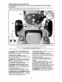
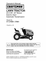
Operator's Manual
CRRFTSMIIN°
LAWN TRACTOR
24.0 HP, 54" Mower
Electric Start
Automatic Transmission
Model No.
917.276860 \ 276861
• Espahol, p. 36
_]_
This product has a low emission engine which operates
differently from previously built engines. Before you start the
engine, read and understand this Owner's Manual.
IMPORTANT:
Read and follow all Safety
Rules and Instructions before
operating this equipment.
For answers to your questions
about this product, Call:
1-800-659-5917
Sears Craftsman Help Line
5 am - 5 pm, Mon - Sat
SEARS, ROEBUCK
AND CO., HOFFMAN
ESTATES,
Visit our Craftsman website:www.sears.com/craftsman
IL 60179
U.S.A.
Warranty ................................................
Safety Rules ..........................................
Product Specifications
...........................
Assembly/Pre-Operation
.......................
Operation .............................................
Maintenance
Schedule ........................
LIMITED
2-YEAR
WARRANTY
ON
2
3
6
8
12
20
CRAFTSMAN
Maintenance
........................................
20
Service and Adjustments
.....................
24
Storage ................................................
31
Troubleshooting
...................................
32
Sears Service ........................
Back Cover
TRACTOR
AND
BATTERY
ON TRACTOR
When used and maintained
according
to the operator's manual instructions,
if this tractor
fails due to a defect in material or workmanship
within two years from the date of purchase, call 1-800-4-MY-HOME®
to arrange for free repair.
During the first 30 days of purchase, there will be no charge to service the product in
your home. For your convenience,
in-home warranty service will still be available after
the first 30 days of purchase, but a trip charge will apply. This charge will be waived if
you transport the product to an authorized
Craftsman drop-off location. For the nearest
authorized
location, call 1-800-4-MY-HOME®.
Tractor
warranty
coverage
does not include:
• Expendable
items which become worn during normal use, including but not limited to
blades, spark plugs, air cleaners, belts, and oil filters.
• Standard maintenance
servicing,
oil changes, or tune-ups.
• Tire replacement
or repair caused by punctures from outside objects, such as nails,
thorns, stumps, or glass.
• Repairs necessary
because of operator abuse, including but not limited to damage
caused by towing objects beyond the capability of the tractor, impacting objects that
bend the frame or crankshaft,
or over-speeding
the engine.
• Repairs necessary
because of operator negligence,
including but not limited to electrical and mechanical
damage caused by improper storage, failure to use the proper
grade and amount of engine oil, failure to keep the deck clear of flammable
debris,
or failure to maintain the equipment
according
to the instructions
contained
in the
operator's
manual.
• Engine (fuel system) cleaning or repairs necessary
because of fuel determined
to be
contaminated
or oxidized (stale). In general, fuel should be used within 30 days of its
purchase date.
• Normal deterioration
and wear of the exterior finishes, or product label replacement.
• The tractor battery, which is covered for only 90 days as stated below.
90-DAYS ON BATTERY
For ninety (90) days from the date of purchase, if the battery included with this tractor is
defective in material or workmanship
(our testing proves it will not hold a charge), it will
be replaced free of charge.
During the first 30 days of purchase, there will be no charges to replace the battery in
your home. For your convenience,
in-home warranty service will still be available after
the first 30 days of purchase, but a trip charge will apply. This charge will be waived if
you transport the battery to an authorized
Craftsman drop-off location. For the nearest
authorized
location, call 1-800-4-MY-HOME®.
All tractor and battery warranty coverage is void if this product is used for commercial
or
rental purposes.
This warranty
applies
only while this product
This warranty gives you specific
vary, from state to state.
legal rights,
is within
the United States.
and you may also have other rights,
Sears, Roebuck and Co., Hoffman Estates, IL 60179
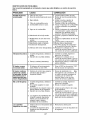
2
which
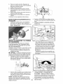
_,DANGER:
This cutting machine is capable of amputating hands and feet and
throwing objects. Failure to observe the following
safety instructions could result
in serious injury or death.
• Never direct discharged
material toward
anyone. Avoid discharging
material
against a wall or obstruction.
Material
may ricochet back toward the operator.
Stop the blades when crossing gravel
surfaces.
,_WARNING:
In order to prevent accidental starting when setting up, transporting, adjusting or making repairs,
always disconnect
spark plug wire and
place wire where it cannot contact spark
plug.
• Do not operate machine without the
entire grass catcher, discharge
guard, or
other safety devices in place and working.
• Slow down before turning.
• Never leave a running machine unattended.
Always turn off blades, set
parking brake, stop engine, and remove
keys before dismounting.
• Disengage
blades when not mowing.
Shut off engine and wait for all parts to
come to a complete stop before cleaning the machine, removing the grass
catcher, or unclogging
the discharge
guard.
• Operate machine only in daylight or
good artificial light.
• Do not operate the machine while under
the influence of alcohol or drugs.
• Watch for traffic when operating near or
crossing roadways.
• Use extra care when loading or unloading the machine into a trailer or truck.
• Always wear eye protection when operating machine.
• Data indicates that operators, age 60
years and above, are involved in a large
percentage
of riding mower-related
injuries. These operators should evaluate
their ability to operate the riding mower
safely enough to protect themselves
and
others from serious injury.
• Follow the manufacturer's
recommendation for wheel weights or counterweights.
• Keep machine free of grass, leaves or
other debris build-up which can touch
hot exhaust / engine parts and burn. Do
not allow the mower to plow leaves or
other debris which can cause build-up
to occur. Clean any oil or fuel spillage
before operating or storing the machine.
Allow machine to cool before
,_I_WARNING:
Do not coast down a hill in
neutral, you may lose control of the tractor.
_,WARNING:
Tow only the attachments
that are recommended
by and comply with
specifications
of the manufacturer
of your
tractor. Use common sense when towing.
Operate only at the lowest possible speed
when on a slope. Too heavy of a load,
while on a slope, is dangerous.
Tires can
lose traction with the ground and cause
you to lose control of your tractor.
_,WARNING:
Engine exhaust, some of
its constituents,
and certain vehicle components contain or emit chemicals
known
to the State of California to cause cancer
and birth defects or other reproductive
harm.
_,WARNING:
Battery
and related accessories
posts, terminals
contain lead and
lead compounds,
chemicals
State of California to cause
known to the
cancer and
birth defects or other reproductive
Wash hands after handling.
I. GENERAL
harm.
OPERATION
• Read, understand,
and follow all instructions on the machine and in the manual
before starting.
• Do not put hands or feet near rotating
parts or under the machine. Keep clear
of the discharge
opening at all times.
• Only allow responsible
adults, who are
familiar with the instructions,
to operate
the machine.
• Clear the area of objects such as rocks,
toys, wire, etc., which could be picked
up and thrown by the blades.
• Be sure the area is clear of bystanders before operating.
Stop machine if
anyone enters the area.
• Never carry passengers.
• Do not mow in reverse unless abso-
storage.
lutely necessary.
Always look down and
behind before and while backing.
3
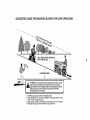
I1. SLOPE
OPERATION
Slopes are a major factor related to loss of
control and tip-over accidents, which can
result in severe injury or death. Operation on all slopes requires extra caution.
If
you cannot back up the slope or if you feel
uneasy on it, do not mow it.
• Mow up and down slopes, not across.
• Watch for holes, ruts, bumps, rocks, or
other hidden objects.
Uneven terrain
could overturn the machine.
Tall grass
can hide obstacles.
• Choose a low ground speed so that you
will not have to stop or shift while on the
slope.
• Do not mow on wet grass. Tires may
lose traction.
Always keep the machine in gear when
going down slopes. Do not shift to neutral and coast downhill.
• Avoid starting, stopping, or turning on a
slope. If the tires lose traction,
disengage the blades and proceed slowly
straight down the slope.
• Keep all movement
on the slopes slow
and gradual.
Do not make sudden
changes in speed or direction, which
could cause the machine to roll over.
• Use extra care while operating machine
with grass catchers or other attachments; they can affect the stability of the
machine. Do no use on steep slopes.
• Do not try to stabilize the machine by
putting your foot on the ground.
• Do not mow near drop-offs, ditches,
or embankments.
The machine could
suddenly roll over if a wheel is over the
edge or if the edge caves in.
II1. CHILDREN
Tragic accidents
can occur if the operator
is not alert to the presence
of children.
Children are often attracted to the machine
and the mowing
activity.
that children
will remain
saw them.
Never assume
where you last
• Keep children out of the mowing area
and in the watchful care of a responsible
adult other than the operator.
• Be alert and turn machine off if a child
enters the area.
• Before and while backing, look behind
and down for small children.
• Never carry children, even with the
blades shut off. They may fall off and
be seriously injured or interfere with
safe machine operation. Children who
have been given rides in the past may
suddenly appear in the mowing area for
another ride and be run over or backed
over by the machine.
• Never allow children
machine.
to operate
the
• Use extra care when approaching
blind
corners, shrubs, trees, or other objects
that may block your view of a child.
IV. TOWING
• Tow only with a machine that has a
hitch designed for towing. Do not attach
towed equipment
except at the hitch
point.
• Follow the manufacturer's
recommendation for weight limits for towed equipment and towing on slopes.
• Never allow children or others in or on
towed equipment.
• On slopes, the weight of the towed
equipment
may cause loss of traction
and loss of control.
• Travel slowly
stop.
and allow extra distance
to
V. SERVICE
SAFE
HANDLING
OF GASOLINE
To avoid personal injury or property
damage, use extreme care in handling
gasoline. Gasoline is extremely flammable
and the vapors are explosive.
• Extinguish
all cigarettes,
cigars, pipes,
and other sources of ignition.
• Use only approved gasoline container.
• Never remove gas cap or add fuel with
the engine running. Allow engine to cool
before refueling.
• Never fuel the machine indoors.
• Never store the machine or fuel container where there is an open flame,
spark, or pilot light such as on a water
heater or other appliances.
• Never fill containers
inside a vehicle or
on a truck or trailer bed with plastic liner.
Always place containers
on the ground
away from your vehicle when filling.
• Keep machine free of grass, leaves, or
other debris build-up.
Clean oil or fuel
spillage and remove any fuel-soaked
debris. Allow machine to cool before
• Remove gas-powered
equipment
from
the truck or trailer and refuel it on the
ground. If this is not possible, then
refuel such equipment
with a portable
container, rather than from a gasoline
dispenser
nozzle.
• Keep the nozzle in contact with the rim
of the fuel tank or container
opening at
all times until fueling is complete. Do not
use a nozzle lock-open device.
• If fuel is spilled on clothing, change
clothing immediately.
• Never overfill fuel tank. Replace gas cap
and tighten securely.
GENERAL
SERVICE
storing.
• If you strike a foreign object, stop and
inspect the machine. Repair, if necessary, before restarting.
• Never make any adjustments
or repairs
with the engine running.
• Check grass catcher components
and
the discharge guard frequently
and replace with manufacturer's
recommended
parts, when necessary.
• Mower blades are sharp. Wrap the
blade or wear gloves, and use extra caution when servicing them.
• Check brake operation frequently.
Adjust
and service as required.
• Maintain or replace safety and instruction labels, as necessary.
• Never operate machine in a closed area.
• Keep all nuts and bolts tight to be sure
the equipment
is in safe working condition.
• Never tamper with safety devices.
Check their proper operation regularly.
• Be alert and turn machine
enters the area.
• Be sure the area is clear of bystanders before operating.
Stop machine if
anyone enters the area.
• Never carry passengers.
• Do not mow in reverse unless absolutely necessary. Always look down and
behind before and while backing.
• Never carry children, even with the
blades shut off. They may fall off and
be seriously injured or interfere with
safe machine operation. Children who
have been given rides in the past may
suddenly appear in the mowing area for
another ride and be run over or backed
off if a child
• Before and while backing, look behind
and down for small children.
• Mow up and down slopes (15 ° Max), not
across.
• Choose a low ground speed so that you
will not have to stop or shift while on the
slope.
• Avoid starting, stopping, or turning on a
slope. If the tires lose traction,
disengage the blades and proceed slowly
straight down the slope.
• If machine stops while going uphill,
disengage blades, shift into reverse and
back down slowly.
• Do not turn on slopes unless necessary, and then, turn slowly and gradually
downhill, if possible.
over by the machine.
• Keep children out of the mowing area
and in the watchful care of a responsible
adult other than the operator.
5
PRODUCT
SPECIFICATIONS
Gasoline Capacity
and Type:
4 Gallons
Unleaded Regular
Oil Type
(API-SG-SL):
SAE 30 (above 32°F)
SAE 5W30
(below 32°F)
Oil Capacity:
W/Filter:
W/O Filter:
Spark Plug:
(Gap: .030")
Ground
Champion
Speed
64 oz.
60 oz.
QC12YC
Forward:
Reverse:
0-5.8
0-2.1
Charging System:
16 Amps
@ 3600 RPM
Battery:
Amp/Hr:
Min. CCA:
Case size:
Blade Bolt Torque:
45-55
35
280
U1R
Ft. Lbs.
CONGRATULATIONS
on your purchase
of a new tractor.
It has been designed,
engineered
and manufactured
to give
you the best possible dependability
and
performance.
Should you experience
any problem you
cannot easily remedy, please contact a
Sears or other qualified service center.
We have competent,
well-trained
representatives and the proper tools to service
or repair this tractor.
Please read and retain this manual.
The
instructions
will enable you to assemble
and maintain your tractor properly. Always
observe the "SAFETY
RULES".
CUSTOMER
RESPONSIBILITIES
• Read and observe the safety rules.
• Follow a regular schedule in maintaining, caring for and using your tractor.
• Follow the instructions
under "Maintenance" and "Storage" sections of this
owner's manual.
_,WARNING:
This tractor is equipped
with an internal combustion
engine and
should not be used on or near any unimproved forest-covered,
brush-covered
or
grass-covered
land unless the engine's
exhaust system is equipped with a spark
arrester meeting applicable
local or state
laws (if any). If a spark arrester is used, it
should be maintained
in effective working
order by the operator.
In the state of California the above is required by law (Section 4442 of the California Public Resources
Code). Other states
may have similar laws. Federal laws apply
on federal lands. A spark arrester for the
muffler is available through your nearest
Sears service center (See REPAIR PARTS
manual).
REPAIR
PROTECTION
AGREEMENTS
Congratulations
on making a smart purchase. Your new Craftsman@ product is
designed and manufactured
for years of
dependable operation. But like all products,
it may require repair from time to time. That's
when having a Repair Protection Agreement
can save you money and aggravation.
Purchase a Repair Protection Agreement
now and protect yourself from unexpected
hassle and expense.
Here's what's included in the Agreement:
• Expert service by our 12,000 profesional repair specialists.
• Unlimited service and no charge for
parts and labor on all covered repairs.
• Product replacement
if your covered
product can't be fixed.
• Discount of 10% from regular price of
service and service-related
parts not
covered by the agreement;
also, 10% off
regular price of preventive maintenance
check.
• Fast help by phone - phone support
from a Sears representative
on products
requiring in-home repair, plus convenient repair scheduling.
Once you purchase the Agreement,
a
simple phone call is all that it takes for you
to schedule service. You can call anytime
day or night, or schedule a service appointment online.
Sears has over 12,000 professional
repair
specialists,
who have access to over 4.5
million quality parts and accessories.
That's the kind of professionalism
you can
count on to help prolong the life of your
new purchase for years to come. Purchase
your Repair Protection Agreement
today!
Some limitations
and exclusions
apply.
For prices and additional
information
call 1-800-827-6655.
SEARS
INSTALLATION
SERVICE
For Sears professional
installation of home
appliances,
garage door openers, water
heaters, and other major home items, in
the U.S.A. call 1-800-4-MY-HOME®
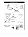
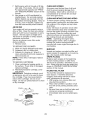
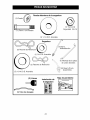
Mower Front Wheel
(1) Wheel
m
(1) Shoulder
(1) Locknut
3/8-16
Bolt
(1) 1-1/40.D.
Washer
Mower
_1)F(1) Front Link
__¢:::_
(1) Anti-Swar Bar
(1) 3/40.D.
Washers
(2) Small Retainer
Springs - 5/16
(2) Rear Lift Link
Assemblies
(5) 1-3/16 O.D. Washers
Mower Install
(2) Keys
Sheet
(1) Oil Drain Tube
For Future Use
7
Slope Sheet
Your new tractor has been assembled
unassembled
for shipping purposes.
TOOLS
REQUIRED
A socket wrench
easier. Standard
are listed below.
FOR
at the factory
with the exception
of those
parts left
ASSEMBLY
set will make assembly
wrench sizes you need
(1) 3/4" wrench
(1) 9/16" wrench
(1) Tire pressure
(1) Pliers
(1) Utility knife
gauge
When right or left hand is mentioned
in
this manual, it means, from your point of
view, when you are in the operating position (seated behind the steering wheel).
TO
REMOVE
TRACTOR
FROM
CARTON
UNPACK
CARTON
1.
Remove all accessible
loose parts and
parts cartons from carton.
2. Cut along dashed lines on all four panels of carton. Remove end panels and
lay side panels flat.
3. Remove mower and packing materials.
4. Check for any additional loose aprts or
cartons and remove.
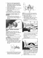
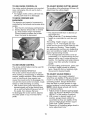
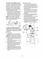
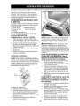
CHECK
BATTERY
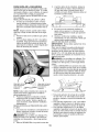
1. Lift hood to raised position.
NOTE: If this battery is put into service
after month and year indicated on label
(L) (label is located between terminals)
charge battery for minimum of one hour at
6-10 amps. (See "BATTERY"
in Maintenance section of this manual for charging
instructions).
NOTE: You may now roll or drive your
tractor off the skid. Follow the appropriate
instruction
below to remove the tractor
from the skid.
,_ WARNING:
Before starting, read, understand and follow all instructions
in the
Operation section of this manual. Be sure
tractor is in a well-ventilated
area. Be sure
the area in front of tractor is clear of other
people and objects.
TO ROLL
Operation
function
Operation
2.
Lift up adjustment
lever (A) and slide
seat until a comfortable
position is
reached which allows you to press
clutch/brake
pedal all the way down.
3. Release lever to lock seat in position.
(See
and
1. Raise attachment
lift lever to its highest
position.
2. Release parking brake by depressing
brake pedal.
3. Place freewheel control in "transmission disengaged
position" (See "TO
TRANSPORT"
in the Operation section
of this manual).
4. Roll tractor forward off skid.
TO DRIVE
ADJUST SEAT
1. Sit in seat.
TRACTOR
OFF SKID
section
for location
of controls)
TRACTOR
OFF SKID (See
section
for location
and
function
of controls)
1. Be sure all the above steps have been
completed.
2. Check engine oil level and fill fuel tank
with gasoline.
3. Place freewheel control in "transmission engaged"
position (see "TO
TRANSPORT"
in Operation
section of
this manual).
4. Sit on seat in operating position, depress brake pedal and set the parking
brake.
5. Raise attachment
lift lever to its highest
position.
6. Removekey from bag and start the
engine (see "TOSTARTENGINE"in
the Operationsectionof this manual).
After enginehas started, movethrottle
controlto idle position.
7. Releaseparking brake.
8. Slowly depressforwarddrive pedal and
drivetractor off skid.
9. Apply braketo stop tractor and set
parking brake.
10.Turnignition key to "STOP"position.
Continuewith the instructionsthat follow.
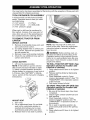
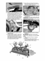
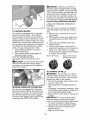
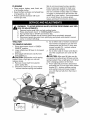
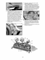
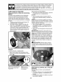
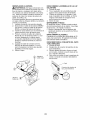
ASSEMBLE
MOWER
1.
FRONT
WHEEL
TO
Using shoulder bolt, washer and
Iocknut from parts bag, assemble front
wheel to mower as shown. Tighten
securely.
INSTALL
BELT
MOWER
AND
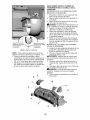
NOTE: Be sure mower side suspension
arms (A) are pointing forward before sliding mower under tractor.
4. Slide mower under tractor until it is
centered under tractor.
5.
FIRST INSTALL ANTI-SWAY
BAR (S).
- From right side of mower, insert
ant-sway bar into hole in transmission
bracket (T).
DRIVE
See MOWER AND DRIVE BELT ASSEMBLY Supplement
Sheet for additional
guidance on this assembly.
Be sure tractor is on level surface and
engage parking brake.
1. Lower attachment
lift lever to it's lowest
- Pivot bar towards you and insert other
end of bar into hole in rear mower
bracket (D). Move mower as needed to
insert bar.
- Secure with washer and retainer
spring as shown.
position.
A CAUTION:
Lift lever is spring loaded.
Have a tight grip on lift lever, lower it
slowly and engage in lowest position.
2. Turn steering wheel to the left as far as
it will go and position mower on right
side of tractor with deflector shield to
the right.
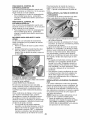
6.
,
Remove plastic tie securing belt, bring
belt forward and check belt for proper
routing in all mower pulley grooves.
9 7.
ATTACH
MOWER
SIDE SUSPENSION
ARMS (A) TO CHASSIS - Position hole
in arm over pin (B) on outside of tractor
chassis and secure with washer and
retainer spring.
Repeat on opposite side of tractor.
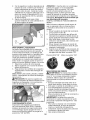
12.Insertotherend of link(E)into holein
frontmowerbracket(H) andsecurewith
washerand retainerspring (J).
8. ATTACHREARLIFTLINKS(C) - Insert
rodend of linkassemblyintohole in tractor liftshaftsuspensionarm (L)and pivot
linkdown to mower.Liftrearcornerof
mowerand positionslot in linkassembly
overpin on rearmowerbracket(D)and
securewith washerand retainerspring.
9. Repeaton oppositesideof tractor.
13.Disengagebelttensionrod(K)from locking bracket(L).
14.Installbeltontoengineclutchpulley(M).
IMPORTANT:Checkbeltforproperrouting
in allmowerpulleygrooves.
10.Turnsteeringwheelto positionwheels
straightforward.
11.ATTACHFRONTLINK(E) - Workfrom
leftsideof tractor.Insertrodend of link
assemblythroughfrontholein tractor
frontsuspensionbracket(F) andsecure
with retainerspring(G)throughholein
linklocatedbehindthe bracket.
15.Engagebelttensionrod (K)on locking
A bracket(L).
CAUTION:Belttensionrod is spring
loaded.Havea tightgrip on rod andengage
slowly.
16.Raiseattachmentlift leverto highest
position.
17.If necessary,adjustgaugewheels
beforeoperatingmoweras shownin the
Operationsectionofthis manual.
02937
10
CHECK
TIRE
PRESSURE
#'CHECKLIST
The tires on your tractor were overinflated
at the factory for shipping purposes.
Correct tire pressure is important for best
cutting performance.
• Reduce tire pressure to PSI shown on
tires.
CHECK
DECK
Before you operate your new tractor, we
wish to assure that you receive the best
performance
and satisfaction
from this
Quality Product.
Please review the following checklist:
v" All assembly instructions
have been
completed.
v" No remaining loose parts in carton.
v" Battery is properly prepared and
charged.
v" Seat is adjusted comfortably
and tightened securely.
v" All tires are properly inflated.
(For shipping purposes, the tires were overinflated at the factory).
v" Be sure mower deck is properly leveled
side-to-side/front-to-rear
for best cutting
results. (Tires must be properly inflated
for leveling).
v" Check mower and drive belts. Be sure
LEVELNESS
For best cutting results, mower housing should be properly leveled. See "TO
LEVEL MOWER" in the Service and
Adjustments
section
CHECK
FOR
OF ALL
BELTS
of this manual.
PROPER
POSITION
See the figures that are shown for replacing motion and mower blade drive belts
in the Service and Adjustments
section
of this manual.
Verify that the belts are
routed correctly.
CHECK
BRAKE
they are routed properly around pulleys
and inside all belt keepers.
v" Check wiring. See that all connections
are still secure and wires are properly
clamped.
v" Before driving tractor, be sure freewheel
control is in "transmission
engaged"
position (see "TO TRANSPORT"
in the
Operation section of this manual).
While learning how to use your tractor,
pay extra attention to the following important items:
v" Engine oil is at proper level.
v" Fuel tank is filled with fresh, clean,
regular unleaded gasoline.
v" Become familiar with all controls, their
location and function.
Operate them
before you start the engine.
v" Be sure brake system is in safe operating condition.
v" Be sure Operator Presence System
and Reverse Operation System (ROS)
are working properly (See the Operation and Maintenance
sections in this
manual).
v" It is important to purge the transmission
before operating your tractor for the first
time. Follow .proper starting and transmission purging instructions
(See "TO
START ENGINE" and "PURGE TRANSMISSION" in the Operation section of
this manual).
SYSTEM
After you learn how to operate your tractor, check to see that the brake is operating properly.
See "TO CHECK BRAKE"
in the Service and Adjustments
section of
this manual.
11
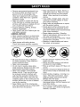
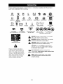
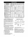
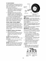
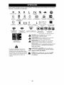
These symbols may appear on your tractor
Learn and understand
their meaning.
R
REVERSE
N
H
NEUTRAL
or in literature
I',,,I
L
HIGH
LOW
CHOKE
supplied
FAST
with the product.
SLOW
IGNITION SWITCH
ENGINE OFF
REVERSE
OPERATION
SYSTEM (ROS)
ENGINE ON
ENGINE START
PARKING
BRAKE
MOWER HEIGHT
MOWER LIFT
4'
LIGHTS ON
FUEL
BATTERY
REVERSE
FORWARD
CRUISE CONTROL
CLUTCH/BRAKE
PEDAL
m
ATTACHMENT
CLUTCH DISENGAGED
ATTACHMENT
CLUTCH ENGAGED
DANGER, KEEP HANDS
AND FEET AWAY
KEEP AREA CLEAR
(SEE SAFETY
SLOPE HAZARDS
RULES SECTION)
DANGER indicates a hazard which, if not avoided,
will result in death or serious injury.
WARNING
hazard
which,
if not avoided,
could result indicates
in death a or
serious
injury.
FREE WHEEL
(Automatic Models only)
CAUTION
which, ifinjury.
not avoided,
might resultindicates
in minora hazard
or moderate
CAUTION when used without the alert symbol,
indicates a situation that could result in damage
to the tractor and/or engine.
Failure to follow instructions
could result in serious injury or
death. The safety alert symbol
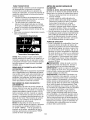
is used to identify safety information about hazards which can
result in death, serious injury
and/or property damage.
,_l,l{llll!,Jtl.,
HOT SURFACES indicates a hazard which,
if not avoided, could result in death, serious
and/or property damage.
FIRE indicates a hazard which, if not avoided,
could result in death, serious injury and/or
property damage.
12
injury
KNOW
YOUR
TRACTOR
READ THIS OWNER'S
TRACTOR
MANUAL
AND SAFETY
RULES
BEFORE
OPERATING
Compare the illustrations
with your tractor to familiarize yourself with the locations
various controls and adjustments.
Save this manual for future reference.
YOUR
of
03079
Our tractors
conform
American
to the applicable safety standards
National Standards
Institute.
(A) ATTACHMENT
LIFT LEVER - Used
to raise and lower the mower or other at-
of the
(H) LIGHT SWITCH -Turns
the headlights on and off.
(J) CRUISE CONTROL
LEVER - Used to
set forward movement of tractor at desired
tachments
mounted to your tractor.
(B) BRAKE PEDAL - Used for braking
the tractor and starting the engine.
(C) PARKING
BRAKE - Locks clutch/
brake pedal into the brake position.
(D) THROTTLE
CONTROL
- Used to
control engine speed.
(E) ATTACHMENT
CLUTCH SWITCH
- Used to engage the mower blades, or
other attachments
mounted to your tractor.
(F) IGNITION
SWITCH - Used for starting
and stopping the engine.
(G) REVERSE
OPERATION
SYSTEM
(ROS) "ON" POSITION - Allows operation of mower or other powered attachment while in reverse.
speed without holding the forward drive
pedal.
(K) FORWARD
DRIVE PEDAL - Used for
forward movement
of tractor.
(L) REVERSE
DRIVE PEDAL
reverse movement
of tractor.
- Used for
(M) FREEWHEEL
CONTROL
- Disengages transmission
for pushing or slowly
towing the tractor with the engine off.
(N) CHOKE CONTROL
- Used when
starting a cold engine.
(P) SERVICE REMINDER
/ HOUR METER
- Indicates when service is required for
the engine and mower.
13
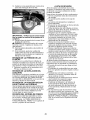
The operation of any tractor can result in foreign objects thrown into the
eyes, which can result in severe eye damage.
Always wear safety glasses
or eye shields while operating your tractor or performing
any adjustments
or repairs. We recommend
standard safety glasses or a wide vision safety
mask worn over spectacles.
HOW
TO
USE
YOUR
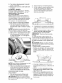
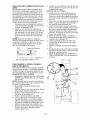
TO SET PARKING
GROUND
TRACTOR
-
• To stop ground drive, depress
pedal all the way down.
BRAKE
Your tractor is equipped with an operator
presence sensing
switch. When engine
is running, any attempt by the operator
to leave the seat without first setting the
parking brake will shut off the engine.
1. Depress brake pedal (B) all the way
down and hold.
2.
DRIVE
ENGINE
brake
-
• Move throttle control (D) between half
and full speed (fast) position.
NOTE:
Failure to move throttle control
between half and full speed (fast) position, before stopping, may cause engine
"backfire".
Pull parking brake lever (C) up and
hold, release pressure from brake
pedal (B), then release parking brake
lever. Pedal should remain in brake
position.
Make sure parking brake will
hold tractor secure.
to
• Turn ignition key (F) to "STOP" position
and remove key. Always remove key
when leaving tractor to prevent unauthorized use.
• Never use choke (N) to stop engine.
IMPORTANT:
Leaving the ignition switch
in any position other than "STOP" will
cause the battery to discharge
and go
dead.
NOTE:
Under certain conditions when
tractor is standing idle with the engine
running, hot engine exhaust gases may
cause "browning" of grass. To eliminate
this possibility, always stop engine when
stopping tractor on grass areas.
,_CAUTION:
Always
stop tractor
pletely, as described
above,
the operator's
position.
before
comleaving
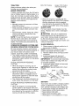
STOPPING
MOWER
BLADES
• To stop mower
clutch
blades,
push attachment
switch in to disengaged
position
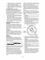
(O).
(I) Attachment
Clutch Switch
Pull Out To "Engage"
(O) Push-In to
"Disengaged"
TO USE THROTTLE
CONTROL
(D)
Always operate engine at full speed (fast).
• Operating engine at less than full speed
(fast) reduces engine's operating efficiency.
• Full speed (fast) offers the best mower
performance.
14
TO USE CHOKE
CONTROL
TO ADJUST
(N)
Use choke control whenever you are starting a cold engine. Do not use to start a
warm engine.
• To engage choke control, pull knob out.
Slowly push knob in to disengage.
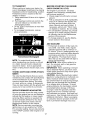
TO MOVE
FORWARD
MOWER
CUTTING
The position of the attachment
determines
the cutting height.
HEIGHT
lift lever (A)
AND
BACKWARD
The direction and speed of movement
is
controlled
by the forward and reverse drive
pedals.
1. Start tractor and release parking brake.
2. Slowly depress forward (K) or reverse
(L) drive pedal to begin movement.
Ground speed increases the further
down the pedal is depressed.
• Put attachment
lift lever in desired cutting height slot.
• Slide pointer tab (T) to desired cutting
height as a reminder for next time you
mow.
TO USE CRUISE
The cutting height range is approximately 1" to 4". The heights are measured from the ground to the blade tip with
the engine not running. These heights
are approximate
and may vary depending
upon soil conditions,
height of grass and
types of grass being mowed.
• The average lawn should be cut to approximately
2-1/2 inches during the cool
season and to over 3 inches during hot
months.
For healthier and better looking
lawns, mow often and after moderate
growth.
• For best cutting performance,
grass over
6 inches in height should be mowed
twice. Make the first cut relatively high;
the second to desired height.
CONTROL
The cruise control feature can be used for
forward travel only.
SYSTEM CHARACTERISTICS
The cruise control should only be used
while mowing or transporting
on relatively
smooth, straight surfaces. Other conditions
such as trimming at slow speeds may
cause the cruise control to disengage.
Do
not use the cruise control on slopes, rough
terrian or while trimmimg or turning.
• With forward drive pedal depressed
to
desired speed, pull cruise control lever
(J) up and hold while lifting your foot off
the pedal, then release the lever.
To disengage the cruise control, depress
the brake pedal or tap on forward drive
pedal.
TO ADJUST
GAUGE
WHEELS
Gauge wheels
are properly adjusted
when they are slightly off the ground when
mower is at the desired cutting height in
operating position. Gauge wheels then
keep the deck in proper position to help
prevent scalping in most terrain conditions.
NOTE: Adjust gauge wheels with tractor
on a flat level surface.
1. Adjust mower to desired cutting height
(See "TO ADJUST MOWER CUTTING
HEIGHT" in this section of manual).
2. With mower in desired height of cut
position, gauge wheels should be
assembled
so they are slightly off the
ground. Install gauge wheel in appropriate hole. Tighten securely.
3. Repeat for all, installing gauge wheel in
same adjustment
hole.
15
AWARNING:
Backing up with the attachment clutch engaged while mowing
is strongly discouraged.
Turning the ROS
"ON", to allow reverse operation with the
attachment
clutch engaged, should only
be done when the operator decides it is
necessary
to reposition the machine with
the attachment
engaged. Do not mow in
reverse
unless absolutely
necessary.
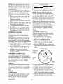
USING THE REVERSE
SYSTEM -
TO OPERATE
Only use if you are certain no children or
other bystanders
will enter the mowing
area.
1. Move motion control lever to neutral
MOWER
Your tractor is equipped with an operator
presence sensing switch. Any attempt
by the operator to leave the seat with the
engine running and the attachment
clutch
engaged will shut off the engine. You must
remain fully and centrally positioned
in the
seat to prevent the engine from hesitating
or cutting off when operating your equipment on rough, rolling terrain or hills.
1. Select desired height of cut with attachment
lift lever.
2. Start mower blades by engaging attachment
clutch control.
TO STOP MOWER BLADES disengage attachment
clutch control.
ACAUTION:
Do not operate
OPERATION
2.
3.
4.
5.
(N) position.
With engine running, turn ignition key
counterclockwise
to ROS "ON" position.
Look down and behind before and
while backing.
Slowly move motion control lever to
reverse (R) position to start movement.
When use of the ROS is no longer
needed, turn the ignition key clockwise
to engine "ON" position.
ROS "ON" Position
Engine "ON" Position
(Normal Operating)
the mower
without either the entire grass catcher,
on mowers so equipped,
or the deflector
shield (S)in place.
TO OPERATE
REVERSE
OPERATION
SYSTEM
ON HILLS
AWARNING:
Do not drive up or down
hills with slopes greater than 15 ° and do
not drive across any slope. Use the slope
guide at the back of this manual.
• Choose the slowest speed before starting up or down hills.
• Avoid stopping or changing speed on
hills.
(ROS)
• If stopping is absolutely necessary,
push
clutch/brake
pedal quickly to brake position and engage parking brake.
• Move motion control lever to neutral (N)
position.
IMPORTANT:
The motion control lever
Your tractor is equipped with a Reverse
Operation System (ROS). Any attempt by
the operator to travel in the reverse direction with the attachment
clutch engaged
will shut off the engine unless ignition key
is placed in the ROS "ON" position.
does not return to neutral (N) position
when the clutch/brake
pedal is depressed.
• To restart movement,
slowly release
parking brake and clutch/brake
pedal.
• Slowly move motion control lever to
slowest setting.
• Make all turns slowly.
16
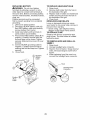
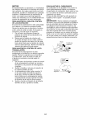
TO TRANSPORT
When pushing or
sure to disengage
freewheel
control
Freewheel control
drawbar of tractor.
1.
2.
BEFORE
towing your tractor, be
transmission
by placing
in freewheeling
position.
is located at the rear
CHECK
Transmission
at more than
reverse
Engaged
ADD
Transmission
CARTS
Disengaged
AND OTHER
ATTACH-
Tow only the attachments
that are recommended by and comply with specifications
of the manufacturer
of your tractor. Use
common sense when towing. Too heavy
of a load, while on a slope, is dangerous.
Tires can lose traction with the ground and
cause you to lose control of your tractor.
SERVICE
Service
REMINDER/HOUR
reminder
shows
METER
the total number
of hours the engine has run and flashes to
indicate that the engine or mower needs
servicing. When service is required, the
service reminder will flash for two hours.
To service engine and mower, see the
Maintenance
section of this manual.
NOTE: Service reminder runs when the
ignition key is in any position but "STOP".
For accurate reading, be sure key remains
in the "STOP" position when engine is not
running.
ENGINE
GASOLINE
• Fill fuel tank to bottom of filler neck. Do
not overfill. Use fresh, clean, regular
unleaded gasoline with a minimum of
87 octane.
(Use of leaded gasoline will
increase carbon and lead oxide deposits
and reduce valve life). Do not mix oil
with gasoline.
Purchase fuel in quantities that can be used within 30 days to
assure fuel freshness.
•6J,CAUTION:
Wipe off any spilled oil or
fuel. Do not store, spill or use gasoline
near an open flame.
IMPORTANT:
When operating in temperatures below32°F(0°C),
use fresh, clean
winter grade gasoline to help insure good
cold weather starting.
CAUTION:
Alcohol blended fuels (called
gasohol or using ethanol or methanol) can
attract moisture which leads to separation and formation of acids during storage.
Acidic gas can damage the fuel system
of an engine while in storage. To avoid
engine problems, the fuel system should
be emptied before storage of 30 days
or longer. Drain the gas tank, start the
engine and let it run until the fuel lines
and carburetor
are empty. Use fresh fuel
next season.
See Storage Instructions
for
additional information.
Never use engine
or carburetor
cleaner products in the fuel
tank or permanent
damage may occur.
NOTE: To protect hood from damage
when transporting
your tractor on a truck
or a trailer, be sure hood is closed and
secured to tractor. Use an appropriate
means of tying hood to tractor (rope, cord,
etc.).
TOWING
MENTS
THE
OIL LEVEL
The engine in your tractor
has been
shipped, from the factory, already filled
with summer weight oil.
1. Check engine oil with tractor on level
ground.
2. Pull up and remove oil fill cap/dipstick;
wipe oil off. Reinsert the dipstick into
the tube and push down firmly into
place. Remove and read oil level. If
necessary, add oil until "FULl" mark
on dipstick is reached.
Do not overfill.
• For cold weather operation you should
change oil for easier starting (See the
oil viscosity chart in the Maintenance
section of this manual).
• To change engine oil, see the Maintenance section in this manual.
Raise attachment
lift lever to its highest
position.
Pull freewheel control out and into the
slot and release so it is held in the
disengaged
position.
• Do not push or tow tractor
two (2) MPH.
• To re-engage
transmission,
above procedure.
STARTING
ENGINE
17
TO START
ENGINE
warm-up period from several seconds
to several minutes, depending
on the
temperature.
When starting the engine for the first time
or if the engine has run out of fuel, it will
take extra cranking time to move fuel from
the tank to the engine.
1. Be sure freewheel control is in the
AUTOMATIC
transmission
engaged position.
Sit on seat in operating position,
depress clutch/brake
pedal and set
parking brake.
3. Place motion control lever in neutral
1. Be sure the tractor is on level ground.
2. Place the motion control lever in
(N) position.
Move attachment
clutch to disengaged
position.
5. Move throttle control to fast position
6. Pull choke control out for a cold engine
start attempt. For a warm engine start
attempt the choke control may not be
needed.
NOTE: Before starting, read the warm
and cold starting procedures
below.
7. Insert key into ignition and turn key
clockwise to start position and release
key as soon as engine starts. Do
not run starter continuously
for more
than fifteen seconds per minute. If the
engine does not start after several
attempts, push choke control in, wait
a few minutes and try again. If engine
still does not start, pull the choke control out and retry.
4.
WEATHER
STARTING
WARM
UP
Before driving the unit in cold weather,
the transmission
should be warmed up as
follows:
2.
WARM
above)
TRANSMISSION
3.
neutral. Release the parking brake and
let the clutch/brake
slowly return to
operating position.
Allow one minute for transmission
to
warm up. This can be done during the
engine warm up period.
• The attachments
can be used during
the engine warm-up period after the
transmission
has been warmed up and
may require the choke control be pulled
out slightly.
NOTE: If at a high altitude (above 3000
feet) or in cold temperatures
(below 32 F)
the carburetor
fuel mixture may need to
be adjusted for best engine performance
(see "TO ADJUST CARBURETOR"
in the
Service and Adjustments
section of this
manual).
U GE TRANSMISSION
CAUTION:
Never engage or disengage freewheel
lever while the engine
is running.
To ensure proper operation and performance,
it is recommended
that the
transmission
be purged before operating
tractor for the first time. This procedure will
remove any trapped air inside the transmission which may have developed during
shipping of your tractor.
IMPORTANT:
Should your transmission
require removal for service or replacement, it should be purged after reinstallation before operating the tractor.
1. Place tractor safely on a level surface
- that is clear of objects and open - with
engine off and parking brake set.
2. Disengage
transmission
by placing
freewheel control in disengaged
position (See "TO TRANSPORT"
in this
section of manual).
3. Sitting in the tractor seat, start engine.
After the engine is running, move
throttle control to slow position. Disen_lgage
parking brake.
AUTION:
At any time, during step
4, there may be movement
of the drive
wheels.
(50 ° F and
8.
When engine starts, slowly push
choke control in until the engine
begins to run smoothly. If the engine
starts to run roughly, pull the choke
control out slightly for a few seconds
and then continue to push the control
in slowly.
• The attachments
and ground drive can
now be used. If the engine does not
accept the load, restart the engine and
allow it to warm up for one minute using
the choke as described above.
COLD WEATHER
STARTING (50 ° F and
below)
8. When engine starts, slowly push
choke control in until the engine
begins to run smoothly. Continue to
push the choke control in small steps
allowing the engine to accept small
changes in speed and load, until the
choke control is fully in. If the engine
starts to run roughly, pull the choke
control out slightly for a few seconds
and then continue to push the control
in slowly. This may require an engine
4.
18
Depress forward drive pedal to full
forward position and hold for five (5)
seconds and release pedal. Depress
reversedrive pedal to full reverseposition and hold for five (5) seconds and
releasepedal. Repeat this procedure
three (3) times.
5. Shutoffengineand set parking brake.
6. Engagetransmissionby placingfreewheelcontrol in engaged position(See
"TOTRANSPORT"in this sectionof
manual).
7. Sitting in the tractor seat, start engine.
After the engine is running, move
throttle controlto half (1/2) speed.
Disengageparking brake.
8. Drivetractor forwardfor approximately
five feet then backwardsfor five feet.
Repeat this driving procedurethree
times.
Yourtransmissionis now purgedand now
readyfor normal operation.
MOWING TIPS
• Tire chains cannotbe used when the
mowerhousingis attachedto tractor.
• Mowershould be properly leveledfor
best mowingperformance. See "TO
LEVEL MOWERHOUSING"in the
Service andAdjustmentssectionof this
manual.
• The left hand side of mowershould be
used for trimming.
• Drive so that clippings are discharged
onto the area that has already been
cut. Havethe cut areato the right of
the tractor. This will result in a more
evendistributionof clippings and more
uniformcutting.
• When mowinglarge areas, start by
turning to the right so that clippingswill
dischargeawayfrom shrubs,fences,
driveways,etc. After one or two rounds,
mow in the oppositedirection making
left hand turns untilfinished.
• If grass is extremelytall, it should be
mowedtwice to reduce load and possible fire hazard from dried clippings.
Makefirst cut relativelyhigh;the second
to the desired height.
• Do not mow grass when it is wet. Wet
grasswill plug mowerand leave undesirable clumps. Allow grass to dry before
mowing.
• Always operate engine at full throttle
when mowing to assurebetter mowing performanceand proper discharge
of material. Regulategroundspeed by
selectinga low enoughspeed to give the
mowercutting performanceas well as
the quality of cut desired.
• When operatingattachments,select a
groundspeed that will suit the terrain
andgive best performanceof the attachment being used.
19
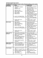
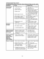
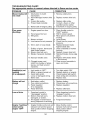
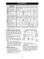
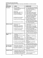
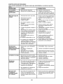
MAINTENANCE
SCHEDULE
BEFORE
EACH
USE
EVERY
EVERY
EVERY
EVERY
EVERY
BEFORE
B
25
so
loo
SEASON STORAQE
HOURS
HOURS
HOURS
HOURS
Check Brake Operation
T
R
Check
Tire Pressure
Check Operator
Presence
& ROS Systern_
A Check for Loose Fasteners
C
Check/Replace
T
Lubrication
0
Check
R
Clean
Mower
Blades
Chart
Battery
Level
Battery
and Terminals
Check
Transaxle
Check
Mower
Check
V-Belts
Check
Enqine
Cooling
Levelness
Oil Level
Change Engine Oil (with oil filter)
Change
Engine
Oil (without
_
Clean Air Filter
G
Clean
I
oil filter
Air Screen
Inspect Muffler/SparkArrester
N Replace Oil Filter !If equipped)
E Clean
Replace
Replace
Re
Engine
Spark
Cooling
Fins
Plug
Air Filter Paper Cartridge
lace Fuel
Filter
.....
1 - Change more often when operating under a heavy load or
in high ambient temperatures.
2 - Service more often when operating in dirty or dusty conditions.
GENERAL
RECOMMENDATIONS
LUBRICATION
The warranty on this tractor does not
cover items that have been subjected to
operator abuse or negligence.
To receive
full value from the warranty, operator
must maintain tractor as instructed
in this
manual.
Some adjustments
will need to be made
periodically
to properly maintain your
tractor.
At least once a season, check to see if
you should make any of the adjustments
described in the Service and Adjustments
section of this manual.
Spindle ii_]
Zerk
CHART
Spindle
Zerk
Front Wheel
Bearing zerk
Engine
Bearing zerk_
Steering
Sector Gear
Teeth
!
_General
Purpose Grease
@Refer to Maintenance
"ENGINE"
A new spark plug and clean air filter
assure proper air-fuel mixture and help
your engine run better and last longer.
Mandrel
Zerks
Section
IMPORTANT:
Do not oil or grease the
pivot points which have special nylon
bearings.
Viscous lubricants will attract
dust and dirt that will shorten the life of the
self-lubricating
bearings.
If you feel they
must be lubricated,
use only a dry, powdered graphite type lubricant sparingly.
BEFORE EACH USE
5.
_
@ Front Wheel
• At least once a year you should replace
the spark plug, clean or replace air filter,
and check blades and belts for wear.
1.
2.
3.
4.
3 - Replace blades more often when mowing in sandy soil.
4 - Not required if equipped with maintenance-free
battery.
Check engine oil level.
Check brake operation.
Check tire pressure.
Check operator presence and
ROS systems for proper operation.
Check for loose fasteners.
20
ROS "ON" Position
TRACTOR
Always observe safety rules when
forming any maintenance.
BRAKE OPERATION
per-
If tractor requires more than five (5) feet to
stop at highest speed in highest gear on a
level, dry concrete or paved surface, then
brake must be serviced. (See "TO CHECK
BRAKE" in the Service and Adjustments
section of this manual).
TIRES
• When the engine is running with the
ignition switch in the ROS "ON" position
and the attachment
clutch engaged,
any attempt by the operator to shift into
reverse should NOT shut off the engine.
BLADE CARE
• Maintain proper air pressure in all tires
(See PSI on tires).
• Keep tires free of gasoline, oil, or insect
control chemicals
which can harm rubber.
For best results mower blades must be
sharp. Replace worn, bent or damaged
blades.
_1, CAUTION:
Use only a replacement
blade approved by the manufacturer
of
your tractor. Using a blade not approved
by the manufacturer
of your tractor is
hazardous, could damage your tractor and
void your warranty.
• Avoid stumps, stones, deep ruts, sharp
objects and other hazards that may
cause tire damage.
NOTE: To seal tire punctures and prevent
flat tires due to slow leaks, tire sealant
may be purchased
from your local parts
dealer. Tire sealant also prevents tire dry
rot and corrosion.
OPERATOR
PRESENCE
SYSTEM AND
REVERSE
OPERATION
SYSTEM
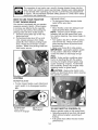
BLADE
Raise mower to highest position to allow access to blades.
NOTE: Protect your hands with gloves
and/or wrap blade with heavy cloth.
2. Remove blade bolt by turning counterclockwise.
3.
Install new blade with stamped
"GRASS SIDE" facing the ground.
IMPORTANT:
To ensure proper assembly,
center hole in blade must align with star
on mandrel assembly.
4. Install and tighten blade bolt securely
(45-55 Ft. Lbs. torque).
IMPORTANT:
Special blade bolt is heat
treated.
Blade
position.
CHECK OPERATOR
SYSTEM
PRESENCE
• When the engine is running, any attempt by the operator to leave the seat
without first setting the parking brake
should shut off the engine.
• When the engine is running and the
attachment
clutch is engaged, any attempt by the operator to leave the seat
should shut off the engine.
• The attachment
clutch should never operate unless the operator is in the seat.
CHECK REVERSE
SYSTEM
OPERATION
REMOVAL
1.
(ROS)
Be sure operator presence and reverse
operation systems are working properly.
If
your tractor does not function as described, repair the problem immediately.
• The engine should not start unless the
brake pedal is fully depressed,
and the
attachment
clutch control is in the disengaged
Engine "ON" Position
(Normal Operating)
Mandrel
Assembly
Blade Bolt
Center Hole
BATTERY
(ROS)
Your tractor has a battery charging
which is sufficient for normal use.
• When the engine is running with the
ignition switch in the engine "ON" position and the attachment
clutch engaged,
any attempt by the operator to shift into
reverse should shut off the engine.
system
How-
ever, periodic charging of the battery with
an automotive
charger will extend its life.
• Keep battery and terminals clean.
• Keep battery bolts tight.
• Keep small vent holes open.
• Recharge at 6-10 amperes for 1 hour.
21
NOTE: The original equipment
battery on
your tractor is maintenance
free. Do not
attempt to open or remove caps or covers.
Adding or checking level of electrolyte
is
not necessary.
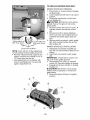
TO CLEAN
BATTERY
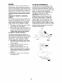
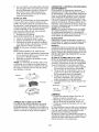
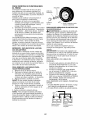
SAE VISCOSITY
F
C
TRANSAXLE
section
of this manual).
TO CHANGE
COOLING
40
0
60
10
ANTICIPATED
80
20
BEFORE
NEXT
100
10
OIL
40
CHANGE
ENGINE
OIL
• Oil will drain more freely when warm.
• Catch oil in a suitable container.
1.
Inspect cooling fan to be sure fan blades
are intact and clean.
• Inspect cooling fins for dirt, grass clippings and other materials.
To prevent
damage to seals, do not use compressed air or high pressure sprayer to
clean cooling fins.
2.
Remove oil fill cap/dipstick.
Be careful
not to allow dirt to enter the engine
when changing oil.
Remove yellow cap from end of drain
valve and install the drain tube onto the
fitting.
Oil Drain Valve
FLUID
The transaxle was sealed at the factory
and fluid maintenance
is not required for
the life of the transaxle.
Should the trans-
LF°C_ed
n_
X
Closed and _
Yellow
{'--2- - -"
_,
o 0 !j..-xW
axle ever leak or require servicing,
contact
your nearest Sears or other qualified
service center.
V-BELTS
Check V-belts
RANGE
32
Determine temperature
range expected
before oil change.
All oil must meet API
service classification
SG-SL.
• Be sure tractor is on level surface.
•
PUMP
30
-10
NOTE:
Although multi-viscosity
oils
(5W30, 10W30 etc.) improve starting in
cold weather, they will result in increased
oil consumption
when used above 32°F.
Check your engine oil level more frequently to avoid possible engine damage from
running low on oil.
Change the oil after every 50 hours of operation or at least once a year if the tractor
is not used for 50 hours in one year.
Check the crankcase
oil level before starting the engine and after each eight (8)
hours of operation.
Tighten oil fill cap/
dipstick securely each time you check the
oil level.
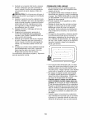
The transmission
fan and cooling fins
should be kept clean to assure proper
cooling.
Do not attempt to clean fan or transmission while engine is running or while the
transmission
is hot. To prevent possible
damage to seals, do not use high pressure
water or steam to clean transaxle.
TRANSAXLE
0
-20
TEMPERATURE
AND TERMINALS
Corrosion and dirt on the battery and
terminals can cause the battery to "leak"
power.
1. Disconnect
BLACK battery cable first
then RED battery cable and remove
battery from tractor.
2. Rinse the battery with plain water and
dry.
3. Clean terminals and battery cable ends
with wire brush until bright.
4. Coat terminals with grease or petroleum jelly.
5. Reinstall battery (See "REPLACING
BATTERY" in the SERVICE AND ADJUSTMENTS
-20
-30
GRADES
,_,
; >. t
j#"
"D rain
Tube
for deterioration
and wear
3.
after 100 hours of operation and replace
if necessary. The belts are not adjustable.
Replace belts if they begin to slip from
wear.
ENGINE
4.
5.
LUBRICATION
6.
Only use high quality detergent
oil rated
with API service classification
SG-SL.
Select the oil's SAE viscosity grade
according to your expected operating
temperatu re.
22
Unlock drain valve by pushing inward
slightly and turning counterclockwise.
To open, pull out on the drain valve.
After oil has drained completely,
close
and lock the drain valve by pushing
inward and turning clockwise until the
pin is in the locked position as shown.
Remove the drain tube and replace the
cap onto the end of the drain valve.
7.
8.
CLEAN
Refill engine with oil through oil fill dipstick tube. Pour slowly. Do not overfill.
For approximate
capacity see "PRODUCT SPECIFICATIONS"
section of this
manual.
Air screen must be kept free of dirt and
chaff to prevent engine damage from
overheating.
Clean with a wire brush or
compressed
air to remove dirt and stubborn dried gum fibers.
Use gauge on oil fill cap/dipstick
for
checking level. For accurate reading,
tighten dipstick cap securely onto the
tube before removing dipstick.
Keep oil
at "FULl" line on dipstick. Tighten cap
onto the tube securely when finished.
CLEAN
dusty conditions.
1. Remove cover.
PRE-CLEANER
Wash it in liquid detergent and water.
Squeeze it dry in a clean cloth.
Saturate it in engine oil. Wrap it in
clean, absorbent
cloth and squeeze to
remove excess oil.
NOTE: If very dirty or damaged,
pre-cleaner.
TO SERVICE
MUFFLER
Inspect and replace corroded muffler and
spark arrester (if equipped)
as it could create a fire hazard and/or damage.
SPARK PLUG(S)
replace
Replace spark plug(s) at the beginning
of each mowing season or after every
100 hours of operation, whichever occurs
first. Spark plug type and gap setting are
shown in "PRODUCT
SPECIFICATIONS"
section of this manual.
CARTRIDGE
1. Clean cartridge
by tapping gently on
flat surface.
If very dirty or damaged,
replace cartridge.
2. Reinstall precleaner
cartridge, cover
and secure.
IN-LINE
FUEL
FILTER
The fuel filter should be replaced once
each season.
If fuel filter becomes
IMPORTANT:
Petroleum solvents, such
as kerosene, are not to be used to clean
the cartridge.
They may cause deterioration of the cartridge.
Do not oil cartridge. Do not use pressurized
air to clean
or dry cartridge.
Cover
AREAS
Every 100 hours of operation (more often
under extremely
dusty, dirty conditions),
remove the blower housing and other cooling shrouds. Clean the cooling fins and
external surfaces as necessary. Make sure
the cooling shrouds are reinstalled.
NOTE:
Operating the engine with a
blocked grass screen, dirty or plugged
cooling fins, and/or cooling shrouds
removed will cause engine damage due to
overheating.
Your engine will not run properly using a
dirty air filter. Clean the foam pre-cleaner
after every 25 hours of operation or every
season.
Service paper cartridge
every
100 hours of operation or every season,
whichever occurs first.
Service air cleaner more often under
2.
3.
4.
AIR INTAKE/COOLING
To insure proper cooling, make sure the
grass screen, cooling fins, and other external surfaces of the engine are kept clean
at all times.
AIR FILTER
TO SERVICE
AIR SCREEN
clogged, obstructing
fuel flow to carburetor, replacement
is required.
1. With engine cool, remove filter and
plug fuel line sections.
2. Place new fuel filter in position in fuel
line with arrow pointing towards carburetor.
3. Be sure there are no fuel line leaks and
4.
Cartridge
clamps are properly positioned.
Immediately
wipe up any spilled
line.
Foam
Clamp
Fuel
23
gaso-
CLEANING
We do not recommend
using a garden
hose or pressure washer to clean your
tractor unless the engine and transmission are covered to keep water out. Water
in engine or transmission
will shorten the
useful life of your tractor. Use compressed
air or a leaf blower to remove grass,
leaves and trash from tractor and mower.
• Clean engine, battery, seat, finish, etc.
of all foreign matter.
• Keep finished surfaces and wheels free
of all gasoline, oil, etc.
• Protect painted surfaces with automotive type wax.
WARNING:
VICE
OR ADJUSTMENTS:
TO AVOID SERIOUS
INJURY,
BEFORE
PERFORMING
ANY SER-
1. Depress brake pedal fully and set parking brake.
2. Place attachment
clutch in "DISENGAGED"
position.
3. Turn ignition key to "STOP" and remove key.
4. Make sure the blades and all moving parts have completely
stopped.
5. Disconnect spark plug wire from spark plug and place wire where it cannot
come in contact with plug.
TRACTOR
TO
REMOVE
6.
Go to either
7.
nect mower suspension
arm (A) from
chassis and rear lift link (C) from rear
mower bracket (D) - remove retainer
springs and washers.
Go to other side of mower and discon-
MOWER
1.
Place attachment
clutch
2.
GAGED" position.
Lower attachment
in "DISEN-
lift lever to its lowest
position.
3. Disengage
belt tension rod (K) from
lock bracket (L).
_i CAUTION:
Belt tension rod is spring
loaded. Have a tight grip on rod and
release slowly.
4. Remove mower belt from electric
clutch pulley (M).
5. Disconnect
front link (E) from mower
- remove retainer spring and washer.
_i
side of mower
and discon-
nect the suspension
arm and rear lift
link.
CAUTION:
After rear lift links are dis-
connected,
the attachment
lift lever will be
spring loaded. Have a tight grip on lift lever
when changing position of the lever.
8. From right side of mower, disconnect
anti-sway bar (S) from right rear mower
bracket (D) - remove retainer spring
and washer and pull mower toward
you until the bar falls from the hole in
bracket.
02937
24
9.
Turn tractor steering wheel to the left
as far as it will go.
10. Slide mower out from under right side
of tractor.
TO INSTALL MOWER
2.
3.
Follow procedure described
in "INSTALL
MOWER AND DRIVE BELT" in the As-
Raise mower to its highest position.
At both sides of mower, position blade
at side and measure the distance
(A) from bottom edge of blade to the
ground. The distance should be the
same on both sides.
sembly section of this manual.
TO LEVEL MOWER
Make sure tires are properly inflated to
the PSI shown on tires.
If tires are over
or under inflated, it may affect the appearance of your lawn and lead you to think
the mower is not adjusted properly.
VISUAL
SIDE-TO-SIDE
ADJUSTMENT
AIL'
1. With all tires properly inflated and if
your lawn appears unevenly cut, determine which side of mower is cutting
lower.
4.
NOTE: As desired, you can raise the low
side of mower or lower the high side.
2. Go to side of mower you wish to adjust.
3. With a 3/4" or adjustable
wrench, turn
lift link adjustment
nut (A) to the left
to lower the mower, or, to the right to
raise the mower.
Turn nut right
to raise mower
If adjustment
is necessary,
and 3 in Visual Adjustment
above.
L -3I A
see steps 2
instructions
5.
Recheck measurements,
adjust if necessary until both sides are equal.
FRONT-TO-BACK
ADJUSTMENT
IMPORTANT:
Deck must be level sideto-side.
To obtain the best cutting results, the
mower blades should be adjusted so the
front tip is 1/8" to 1/2" lower than the rear
tip when the mower is in its highest position.
CAUTION:
Blades are sharp. Protect
your hands with gloves and/or wrap blade
with heavy cloth.
• Raise mower to highest position.
• Position any blade so the tip is pointing
straight forward. Measure distance (B)
to the ground at front and rear tip of the
blade.
Turn nut left
to lower mower
NOTE: Each full turn of adjustment
nut will
change mower height about 3/16".
4. Test your adjustment
by mowing some
uncut grass and visually checking the
appearance.
Readjust, if necessary,
until you are satisfied with the results.
• If front tip of blade is not 1/8" to 1/2"
lower than the rear tip, go to the front of
tractor.
• With an 11/16" or adjustable wrench,
loosen jam nut A several turns to clear
adjustment
nut B.
• With a 3/4" or adjustable wrench, turn
front link adjustment
nut (B) clockwise
(Itighten) to raise the front of mower, or,
counterclockwise
(loosen) to lower the
front mower.
PRECISION
SIDE-TO-SIDE
ADJUSTMENT
1.
With all tires properly inflated, park
tractor on level ground or driveway.
CAUTION:
Blades are sharp. Protect
your hands with gloves and/or wrap blade
with heavy cloth.
25
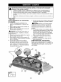
TO REPLACE
MOWER
DRIVE
MOWER DRIVE BELT
BELT REMOVAL
1. Park tractor on a level surface. Engage
parking brake.
2. Lower attachment
lift lever to its lowest
position.
3. Disengage
belt tension rod (K) from
,_ock
bracket (L).
CAUTION:
Belt tension rod is spring
loaded. Have a firm grip on rod and release slowly.
4. Remove screws (P) from R.H. and L.H.
mandrel covers and remove covers
(Q).
5.
Tighten adjust nut
B to raise mower
Loosen adjust nut
B to lower mower
6.
Remove any dirt or grass clippings
which may have accumulated
around
mandrels and entire upper deck surface.
Remove belt from electric clutch pulley
(M), both mandrel pulleys (R) and all
idler pulleys (S).
MOWER
Loosen jam nut A first
DRIVE
BELT INSTALLATION
1.
Install belt around both mandrel pulleys (R) and around idler pulleys (S) as
shown.
2. Install belt onto electric clutch pulley
(U).
IMPORTANT:
Check belt for proper routing in all mower pulley grooves.
3. Reassemble
R.H. and L.H. mandrel
NOTE:
Each full turn of the adjustment
nut will change mower height about 1/8".
• Recheck measurements,
adjust if necessary until front tip of blade is 1/8" to
1/2" lower than the rear tip.
• Hold adjustment
nut in position with
wrench and tighten jam nut securely
against adjustment
nut.
covers (Q). Securely tighten all screws.
Engage belt tension rod (K) on locking
bracket (L).
A CAUTION:
Belt tension rod is spring
loaded. Have a tight grip on rod and engage slowly.
5. Raise attachment
lift lever to highest
position.
4.
®
26
TO ADJUST
ATTACHMENT
CLUTCH
BELT INSTALLATION
1.
The electric clutch should provide years
of service. The clutch has a built-in brake
that stops the pulley within 5 seconds.
Eventually, the internal brake will wear
which may cause the mower blades to
not engage, or, to not stop as required.
Adjustments
should be made by a Sears
or other qualified service center.
1. Make sure attachment
clutch and ignition switches are in "OFF" position.
2. Adjust the three nylon Iocknuts until
space between clutch plate and rotor
measures
.012" at all three slot loca-
2.
3.
4.
5.
tions cut in the side of brake plate.
NOTE: After installing a new electric
clutch, run tractor at full throttle and
engage and disengage electric clutch 10
cycles to wear in clutch plate.
Rotor
6.
7.
8.
9.
TO REPLACE
MOTION
DRIVE
BELT
Park the tractor on level surface.
Engage
parking brake. For ease of service there is
a belt installation
guide decal on bottom of
left footrest.
BELT REMOVAL
-
1.
Remove mower (See "TO REMOVE
MOWER" in this section of manual).
NOTE: Observe entire motion drive belt
and position of all belt guides and keepers.
2. Disconnect
clutch wire harness (A).
3. Remove anti-rotation
link (B) on right
side of tractor.
4.
5.
6.
7.
8.
Remove belt from stationary idler (C)
and clutching idler (D).
Remove belt from centerspan
idler (E).
Pull belt slack toward rear of tractor.
Carefully remove belt upwards from
transmission
input pulley and over
cooling fan blades (F).
Remove belt downward
from engine
pulley and around electric clutch (G).
Slide belt toward rear of tractor, off the
steering plate (H) and remove from
tractor.
27
-
Install new belt from tractor
rear to
front, over the steering plate (H) and
above clutch brake pedal shaft (J).
Pull belt toward front of tractor and roll
belt around electric clutch and onto
engine pulley (G).
Pull belt toward rear of tractor.
Care-
fully work belt down around transmission cooling fan and onto the input
pulley (F). Be sure belt is inside the
belt keeper.
Install belt on centerspan
idler (E).
Install belt through stationary
idler (C)
and clutching idler (D).
Reinstall anti-rotation
link (B) on right
side of tractor. Tighten securely.
Reconnect
clutch harness (A).
Make sure belt is in all pulley grooves
and inside all belt guides and keepers.
Install mower (See "TO INSTALL
MOWER" in this section of manual).
TO CHECK
BRAKE
Washers
If tractor requires more than five (5) feet to
stop at highest speed in highest gear on a
level, dry concrete or paved surface, then
brake must be serviced.
Retaining
Ring
You may also check brake by:
1. Park tractor on a level, dry concrete or
paved surface, depress clutch/brake
pedal all the way down and engage
parking brake.
2. Disengage
transmission
by placing
freewheel
control in "transmission
dis-
I
Axle Cover
_Square
Key (Rear
Wheel Only)
engaged"
position. Pull freewheel control out and into the slot and release so
it is held in the disengaged
position.
The rear wheels must lock and skid
TO START
TERY
when you try to manually push the tractor
forward. If the rear wheels rotate, then the
brake needs to be serviced. Contact a
_,WARNING:
Lead-acid batteries generate explosive gases. Keep sparks, flame
and smoking materials away from batteries. Always wear eye protection when
around batteries.
Sears
or other qualified
FRONT WHEEL
Your new tractor
service
center.
TOE-IN/CAMBER
front wheel toe-in
not adjustable.
If damage has occurred to
affect the factory set front wheel toe-in or
camber, contact a Sears or other qualified
service center.
WHEEL
FOR REPAIRS
1.
2.
Block up axle securely.
Remove axle cover, retaining ring and
washers to allow wheel removal (rear
wheels have a square key - Do not
lose).
3. Repair tire and reassemble.
NOTE: On rear wheels only: align
grooves in rear wheel hub and axle. Insert
square key.
4. Replace washers and snap retaining
ring securely in axle groove.
5. Replace axle cover.
NOTE: To seal tire punctures and prevent
flat tires due to slow leaks, purchase and
use tire sealant from Sears. Tire sealant
also prevents
WITH
A WEAK
BAT-
If your battery is too weak to start the
engine, it should be recharged.
(See "BATTERY" in the MAINTENANCE
section of
this manual).
If "jumper cables" are used for emergency
starting, follow this procedure:
IMPORTANT:
Your tractor is equipped
with a 12 volt system. The other vehicle
must also be a 12 volt system. Do not use
your tractor battery to start other vehicles.
and
camber is set at the factory and is normal.
The front wheel toe-in and camber are
TO REMOVE
ENGINE
TO ATTACH
JUMPER
CABLES
-
1. Connect
one end of the RED cable
2.
to the POSITIVE
(+) terminal of each
battery(A-B),
taking care not to short
against tractor chassis.
Connect one end of the BLACK cable
3.
to the NEGATIVE
(-) terminal (C) of
fully charged battery.
Connect the other end of the BLACK
cable (D) to good chassis ground,
away from fuel tank and battery.
TO REMOVE
ORDER 1. BLACK
tire dry rot and corrosion.
2.
CABLES,
cable first from chassis
and
then from the fully charged battery.
RED cable last from both batteries.
Weak or Dead
Battery
28
REVERSE
Fully Charged
Battery
REPLACING
BATTERY
TO REPLACE
1.
2.
_IWARNING:
Do not short battery
terminals by allowing a wrench or any
other object to contact both terminals at
the same time. Before connecting
battery,
remove metal bracelets, wristwatch
bands,
rings, etc.
Positive terminal must be connected
HEADLIGHT
Raise hood.
Remove bulb holder
BULB
from the hole in
the backside of the grill.
3. Replace bulb in holder and install bulb
holder securely back into the hole in
the backside of the grill.
4. Close hood.
INTERLOCKS
AND RELAYS
first to prevent sparking from accidental
grounding.
1. Lift hood to raised position.
2. Disconnect
BLACK battery cable (A)
then RED battery cable and carefully
remove battery from tractor.
3. Install new battery with terminals in
same position as old battery.
4. First connect RED battery cable (B) to
positive (+) battery terminal with hex
bolt and keps nut as shown. Tighten
securely. Slide terminal cover (C) over
terminal.
5. Connect BLACK grounding cable to
negative (-) battery terminal with remaining hex bolt and keps nut. Tighten
securely
6. Close hood.
Loose or damaged wiring may
your tractor to run poorly, stop
prevent it from starting.
• Check wiring. See electrical
diagram in the Repair Parts
TO REPLACE
FUSE
cause
running,
or
wiring
section.
Replace with 30 amp automotive-type
plug-in fuse. The fuse holder is located
behind the dash.
TO REMOVE
SEMBLY
AND GRILL AS-
1.
Raise hood.
2.
3.
Unsnap headlight wire connector.
Stand in front of tractor. Grasp hood at
sides, tilt toward engine and lift off of
tractor.
When replacing hood, be sure to reconnect the headlight wire connector.
4.
_ Negative
(Black)
Cable
HOOD
Hood
Headlight Wire
Connector
Positive
(Bed)
Cable
29
ENGINE
TO ADJUST
Maintenance,
repair, or replacement
of
the emission control devices and systems,
which are being done at the customers expense, may be performed
by any non-road
engine repair establishment
or individual.
Warranty repairs must be performed
by an
authorized
engine manufacturer's
service
outlet.
TO ADJUST THROTTLE
CONTROL
CABLE
Your carburetor
is not adjustable. If your
engine does not operate properly due to
suspected carburetor
problems, take your
tractor to a Sears or other qualified service
center for repair and/or adjustment.
High speed stop is factory adjusted.
Do
not adjust - damage may result.
IMPORTANT:
Never tamper with the
engine governor, which is factory set
for proper engine speed. Overspeeding the engine above the factory high
speed setting can be dangerous.
If you
think the engine-governed
high speed
needs adjusting, contact a Sears or other
qualified service center,, which has proper
equipment
and experience
to make any
necessary
adjustments.
The throttle control has been preset at the
factory and adjustment
should not be necessary. Check adjustment
as described
below before loosening cable. If adjustment is necessary, proceed as follows:
1. With engine not running, move throttle
control lever to fast position.
2. Check that swivel is against stop. If it is
not, loosen cable clamp screw and pull
cable back until swivel is against stop.
Tighten cable clamp screw securely.
TO ADJUST
CHOKE CONTROL
Sto
The choke control has been preset at
the factory and adjustment
should not be
necessary. Check adjustment
as described
below before loosening cable. If adjustment is necessary, proceed as follows:
1. With engine not running, move choke
control (located on dash panel) to full
choke position.
2. Loosen knob and remove cover as3.
4.
CARBURETOR
Swivel
Clamp
Screw
sembly from air cleaner.
Choke should be closed. If it is not,
loosen casing clamp screw and move
choke cable until choke is completely
closed. Tighten casing clamp screw
securely.
Replace air cleaner cover assembly
and tighten knob.
i
30
acids during storage. Acidic gas can damage the fuel system of an engine while in
storage.
• Empty the fuel tank by starting the engine and letting it run until the fuel lines
and carburetor
are empty.
• Never use engine or carburetor cleaner
products in the fuel tank or permanent
damage may occur.
• Use fresh fuel next season.
Immediately
prepare your tractor for storage at the end of the season or if the trac_i_ will not be used for 30 days or more.
WARNING:
Never store the tractor
with gasoline in the tank inside a building
where fumes may reach an open flame
or spark. Allow the engine to cool before
storing in any enclosure.
TRACTOR
When tractor is to be stored for a period
of time, clean it thoroughly,
remove all dirt,
grease, leaves, etc. Store in a clean, dry
area.
1.
Clean entire tractor
in the Maintenance
NOTE: Fuel stabilizer is an acceptable
alternative
in minimizing
the formation of
fuel gum deposits during storage. Add
stabilizer to gasoline in fuel tank or storage container.
Always follow the mix ratio
found on stabilizer container.
Run engine
at least 10 minutes after adding stabilizer
to allow the stabilizer to reach the carburetor. Do not empty the gas tank and carburetor if using fuel stabilizer.
ENGINE OIL
(See "CLEANING"
section of this
manual).
Inspect and replace belts, if necessary
(See belt replacement
instructions
in
the Service and Adjustments
section of
this manual).
3. Lubricate as shown in the Maintenance
section of this manual.
2.
4.
5.
Drain oil (with engine warm) and replace
with clean engine oil. (See "ENGINE" in
the Maintenance
section of this manual).
CYLINDER(S)
Be sure that all nuts, bolts and screws
are securely fastened.
Inspect moving
parts for damage, breakage and wear.
Replace if necessary.
Touch up all rusted or chipped paint
surfaces; sand lightly before painting.
1.
2.
3.
BATTERY
• Fully charge the battery for storage.
• After a period of time in storage, battery
may require recharging.
• To help prevent corrosion and power
leakage during long periods of storage,
battery cables should be disconnected
and battery cleaned thoroughly
(see "TO
CLEAN BATTERY AND TERMINALS"
in
4.
Replace
with new spark plug(s).
OTHER
• Do not store gasoline from one season
to another.
• Replace your gasoline can if your can
starts to rust. Rust and/or dirt in your
gasoline will cause problems.
• If possible, store your tractor indoors
and cover it to give protection from dust
and dirt.
• Cover your tractor with a suitable protective cover that does not retain mois-
the Maintenance
section of this manual).
• After cleaning, leave cables disconnected and place cables where they
cannot come in contact with battery
terminals.
•
Remove spark plug(s).
Pour one ounce of oil through spark
plug hole(s) into cylinder(s).
Turn ignition key to start position for a
few seconds to distribute oil.
ture. Do not use plastic.
Plastic cannot
breathe which allows condensation
to
form and will cause your tractor to rust.
IMPORTANT:
Never cover tractor while
If battery is removed from tractor for
storage, do not store battery directly on
concrete or damp surfaces.
ENGINE
engine
FUEL SYSTEM
IMPORTANT:
It is important to prevent
gum deposits from forming in essential
fuel system parts such as carburetor, fuel
hose, or tank during storage. Also, alcohol
blended fuels (called gasohol or using
ethanol or methanol) can attract moisture
which leads to separation
and formation of
31
and exhaust
areas are still warm.
TROUBLESHOOTING
CHART:
See appropriate section in manual unless directed to Sears service center
PROBLEM
Will not start
CAUSE
1. Out of fuel.
2. Engine not "CHOKED"
properly.
3. Engine flooded.
4.
5.
6.
7.
8.
Bad spark plug.
Weak or dead battery.
Dirty air filter.
Dirty fuel filter.
Water in fuel.
9. Loose or damaged wiring.
10. Carburetor
out of adjustment.
11. Engine valves out of
adjustment.
Hard to start
Engine will not
turn over
CORRECTION
Fill fuel tank.
See "TO START ENGINE" in
Operation section.
3. Wait several minutes before
attempting
to start.
4. Replace spark plug.
5. Recharge or replace battery.
6. Clean/replace
air filter.
7. Replace fuel filter.
8. Empty fuel tank and carburetor, refill tank with fresh gasoline and replace fuel filter.
9. Check all wiring.
10. See "To Adjust Carburetor"
in Service and Adjustments
section.
11. Contact a Sears or other
1.
2.
qualified
1.
2.
3.
4.
5.
Dirty air filter.
Bad spark plug.
Weak or dead battery.
Dirty fuel filter.
Stale or dirty fuel.
1.
2.
3.
4.
5.
6.
7.
Loose or damaged wiring.
Carburetor
out of adjustment.
6.
7.
8. Engine valves out of
adjustment.
8.
1.
2.
3.
4.
5.
6.
7.
8.
1.
2.
3.
4.
5.
6.
7.
8.
Brake pedal not depressed.
Attachment clutch is engaged.
Weak or dead battery.
Blown fuse.
Corroded battery terminals.
Loose or damaged wiring.
Faulty ignition switch.
Faulty solenoid or starter.
service
center.
Clean/replace
air filter.
Replace spark plug.
Recharge or replace battery.
Replace fuel filter.
Empty fuel tank and refill tank
with fresh, clean gasoline.
Check all wiring.
See "To Adjust Carburetor"
in
Service and Adjustments
section.
Contact a Sears or other
qualified service center.
Depress brake pedal.
Disengage attachment clutch.
Recharge or replace battery.
Replace fuse.
Clean battery terminals.
Check all wiring.
Check/replace
ignition switch.
Check/replace
solenoid or
starter.
Contact a Sears or other
qualified service center.
9. Faulty operator presence
switch(es).
9.
Engine clicks but
will not start
1.
2.
3.
4.
Weak or dead battery.
Corroded battery terminals.
Loose or damaged wiring.
Faulty solenoid or starter.
1.
2.
3.
4.
Recharge or replace battery.
Clean battery terminals.
Check all wiring.
Check/replace
solenoid or
starter.
Loss of power
1.
Cutting too much grass/too
fast.
Throttle in "CHOKE" position.
Build-up of grass, leaves and
trash under mower.
Dirty air filter.
Low oil level/dirty oil.
1.
Raise cutting height/reduce
speed.
Adjust throttle control.
Clean underside of mower
housing.
Clean/replace
air filter.
Check oil level/change
oil.
2.
3.
4.
5.
32
2.
3.
4.
5.
TROUBLESHOOTING
See
appropriate
PROBLEM
Loss of power
(continued)
CHART:
section
in manual
Faulty spark plug.
6.
7.
8.
Dirty fuel filter.
Stale or dirty fuel.
7.
8.
9.
Water
in fuel.
9.
plug wire loose.
10.
Dirty engine air screen/fins.
Dirty/clogged
muffler.
Loose or damaged wiring.
Carburetor
out of adjustment.
11.
12.
13.
14.
15. Engine valves
adjustment,
1. Worn,
2.
3.
,
to Sears
service
center
CORRECTION
6.
11.
12.
13.
14.
Engine dies when
tractor is shifted
into reverse
directed
CAUSE
10. Spark
Excessive
vibration
unless
out of
bent or loose
blade.
Bent blade mandrel.
Loose/damaged
Clean and regap or change
spark plug.
Replace fuel filter.
Empty fuel tank and refill tank
with fresh, clean gasoline.
Empty fuel tank and carburetor, refill tank with fresh gasoline and replace fuel filter.
Connect and tighten spark
plug wire.
Clean engine air screen/fins.
Clean/replace
muffler.
Check all wiring.
See "To Adjust Carburetor"
in Service and Adjustments
section.
15. Contact
qualified
a Sears
service
1. Replace
bolt.
2. Contact
blade. Tighten
a Sears
or other
center.
blade
or other
qualified service center.
3. Tighten loose part(s).
Replace damaged parts.
part(s).
Reverse operation system
(ROS) is not "ON" while
mower or other attachment
,
Turn ignition key to
ROS "ON" position.
See Operation section.
is engaged.
Engine continues
to run when
operator leaves
seat with
attachment
clutch engaged
Poor cut - uneven
,
Faulty operator-safety
presence control system.
,
Check wiring, switches and
connections.
If not corrected,
contact a Sears or other
qualified
,
2.
3.
4.
5.
Worn,
Mower
bent or loose
blade.
deck not level.
Buildup of grass, leaves,
trash under mower.
Bent blade mandrel.
and
Clogged mower deck vent
from build-up of grass, leaves,
and trash around mandrels.
33
service
center.
1. Replace blade. Tighten blade
bolt.
2. Level mower deck.
3. Clean underside of mower
4.
housing.
Contact a Sears
5.
qualified service center.
Clean around mandrels
open vent holes.
or other
to
TROUBLESHOOTING
CHART:
See appropriate section in manual unless directed to Sears service center
PROBLEM
Mower blades will
not rotate
Poor grass
discharge
CAUSE
CORRECTION
1. Obstruction
mechanism.
1. Remove obstruction.
in clutch
2.
Worn/damaged
belt.
3.
4.
Frozen
Frozen
idler pulley.
blade mandrel.
5.
Mower
belt off engine
1. Engine
speed
mower drive
pulley.
too slow.
too fast.
2.
Replace
3.
4.
Replace idler pulley.
Contact a Sears or other
3.
qualified service center.
Install belt on engine pulley.
1.
Place throttle
2.
3.
Travel speed
Wet grass.
4.
5.
Mower not level.
Low/uneven
tire air pressure.
4.
5.
6.
Worn,
6.
7.
8.
Buildup of grass, leaves and
trash under mower.
Mower drive belt worn.
9.
Blades
bent or loose
10. Improper
improperly
blades
blade.
installed.
used.
11. Clogged mower vent
holes from buildup of grass,
leaves, and trash around
mandrels.
2.
3.
7.
8.
9.
mower
drive belt.
control
in
"FAST" position.
Shift to slower speed.
Allow grass to dry before
mowing.
Level mower.
Check tires for proper air
pressure.
Replace/sharpen
blade.
Tighten blade bolt.
Clean underside of mower
housing.
Replace
Reinstall
down.
mower drive belt.
blades sharp edge
10. Replace with blades listed
in this manual.
11. Clean around mandrels to
open vent holes.
Headlight(s) not
working
(if so equipped)
1.
2.
3.
4.
5.
Battery will not
charge
1. Bad battery cell(s).
2. Poor cable connections.
1. Replace battery.
2. Check/clean
all connections.
3.
3.
Replace
regulator.
4.
Replace
alternator.
1.
2.
Place freewheel control in
"engaged"
position.
Replace motion drive belt.
3.
Purge transmission.
4.
Loss of drive
Engine "backfires'
when turning
engine "OFF"
Light switch is "OFF".
Bulb(s) or lamp(s) burned out.
Faulty light switch.
Loose or damaged wiring.
Blown fuse.
Faulty regulator
(if so equipped).
Faulty alternator.
1. Freewheel control in
"disengaged"
position.
2. Motion drive belt worn,
damaged,
or broken.
3. Air trapped in transmission
during shipment or servicing.
,
Engine throttle control not set
between half and full speed
(fast) position before stopping
engine.
34
1. Turn light switch "ON".
2. Replace bulb(s) or lamp(s).
3. Check/replace
light switch.
4. Check wiring and connections.
5. Replace fuse.
,
Move throttle
control
between half and full speed
(fast) position before
stopping engine.
SUGGESTED
GUIDE FOR SIGHTING
SLOPES
FOR SAFE OPERATION
ONLY RIDE UP AND DOWN HILL,
NOT ACROSS HILL
15 DEGREES MAX.
down the face of slopes, never across the face. Do not mow
WARNING:
To avoid
serious
injury,
operate
tractor
and
slopes greater
than 15
degrees.
Make
turns your
gradually
to up
prevent
tipping or loss of control. Exercise extreme caution when
changing direction on slopes.
1. Fold this page along dotted line indicated above.
2. Hold page before you so that its ]eft edge is vertically parage] to a tree
trunk or other upright structure.
3. Sight across the fold in the direction of hill slope you want to measure.
4. Compare the angle of the fold with the slope of the hill.
LO
03
Garantia .......................................................
Reglas de Seguridad ...................................
Especificaciones del Producto .....................
Montaje/Pre Operaci6n ................................
Operaci6n ....................................................
Mantenimiento .............................................
Programa de Mantenimiento .......................
GARANTJA LIMITADA
2 ANOS
PARA
36
37
38
42
46
54
54
Servicio y Ajustes ........................................
58
Almacenamiento ..........................................
65
Identificaci6n de Problemas ........................ 65
Servicio Sears ................................ Contratapa
Partes de Repuesto ........ Vea el Manual Ingles
Ingl6s del DueSo
PARA EL TRACTOR
Y LA BATERJA CRAFTSMAN
EL TRACTOR
Siempre que su uso y mantenimiento se realicen de acuerdo alas instrucciones del Manual del
Operador, si este tractor Ilega a fallar debido a un defecto de materiales o de fabricaci6n dentro
de un plazo de dos (2) aSos a partir de la fecha de compra, Ilame al 1-800-4-MY-HOME®, o bien
gestione una reparaci6n sin cargo.
Durante los primeros 30 dias de dicho plazo, no se le cobrar_t nada por reparar el producto en su
domicilio. Para su conveniencia, podr_, seguir contando con la posibilidad de obtener el service de
la garantia a domicilio una vez transcurridos los primeros 30 dias, pero en ese caso deber_, pagar
un vi_.tico. Usted podr_, evitarse el costo del vi_ttico si Ileva el producto a un centro de servicios
autorizado de Craftsman. Para saber cu_tl le queda m_.s cerca, Ilame al 1-800-4-MY-HOME®.
La cobertura
de la garanfia
del tractor
no incluye:
• Aquellos elementos fungibles que se desgasten por el uso normal, incluidos, de manera no
taxativa, las cuchillas, bujias, filtros de aire, correas y filtros de aceite.
• Los servicios de mantenimiento est_.ndar, cambios de aceite o ajustes de motor.
• Los cambios o reparaciones de neum_.ticos pinchados por objetos extrahos, tales como clavos,
espinas, tocones o trozos de vidrio.
• Las reparaciones que sea preciso hacer debido a malas t6cnicas de manejo por parte del
operador, entre las que se incluyen, de manera no taxativa, los da_os causados por arrastrar
objetos yendo m_.s all_. de la capacidad del tractor, el choque con objetos que tuerzan el marco
o el eje del cigQe_al, o la aceleraci6n excesiva del motor.
• Las reparaciones que sea preciso hacer debido a la negligencia del operador, entre las que
se incluyen, de manera no taxativa, los daSos el6ctricos y mec_.nicos por guardar la unidad
de manera incorrecta, la no utilizaci6n del grado y la calidad apropiados de aceite para motor,
el no mantener el piso libre de restos y escombros que puedan entrar en combusti6n, o el no
mantener el equipo de acuerdo a las instrucciones del manual del operador.
• Las limpiezas o reparaciones del motor (sistema de combustible) que sea preciso hacer porque
se prueba que el combustible est,. contaminado u oxidado (pasado). En general, se debe utilizar el combustible dentro de los 30 dias posteriores a su fecha de compra.
• El deterioro y desgaste normales de las terminaciones exteriores, o la sustituci6n de las etiquetas del producto.
• La bateria, la cual est,. cubierta por s61o 90 dias, como se establece a continuaci6n.
90 DIAS PARA LA BATERIA
Por un plazo de noventa (90) dias a partir de la fecha de compra, si la bateria que viene con este
tractor presenta algt3n defecto de materiales o de fabricaci6n (al probarla, comprobamos que no
mantiene la carga), le ser_. reemplazada sin costo.
Durante los primeros 30 dias a partir de la compra, no se le cobrar_, por realizar el reemplazo de la
bateria en su domicilio. Para su conveniencia, podr_, seguir contando con la posibilidad de obtener
el servicio de la garantia a domicilio, pero en ese caso, deber_t pagar un vi_.tico. Usted podr_, evitarse el costo del vi_.tico si Ileva la bateria a un Centro de Servicios autorizado de Craftsman. Para
saber cu_.l le queda m_.s cerca, Ilame al 1-800-4-MY-HOME®.
La totalidad de la cobertura de la garantia del tractor y la bateria quedar_, sin efecto en caso que el
producto sea utilizado con fines comerciales o de alquiler.
La presente garantia s61o ser_t aplicable si el producto se encuentra dentro de los Estados Unidos.
La presente garantia le otorga derechos legales especificos. Por otra parte, puede que usted
tenga otros derechos, los cuales varian de estado a estado.
Sears,
Roebuck
and Co., Hoffman
Estates,
36
IL 60179
_PELIGRO:
Esta Maquina cortadora es capaz de amputar las manosy los pies y de lanzar
objetos, si no se observan las instrucciones de seguridad siguientes se pueden producir
lesiones graves o la muerte.
_,ADVERTENCIA:
Siempre desconecte el
alambre de la bujfa y p6ngalo doncle no puecla
entrar en contacto con la bujfa, para evitar el
arranque por accidente, clurante la preparaci6n,
el transporte, el ajuste o cuando se hacen
reparaclones.
_,ADVERTENClA:
No avance cuesta abajo a
punto muerto ya que podrfa percler el control
clel tractor.
• No hacer funcionar la m_.quina sin el
captaclor de hierba entera, la protecci6n de
clescarga u otros clispositivos de seguriclacl
en su lugar yen buenas concliciones.
• Ralentizar antes de girar.
• Nunca clejar una m_.quina encenclicla sin vigilancia. Apagar siempre las cuchillas, poner el
freno de estacionamiento, parar el motor, y
quitar las Ilaves antes de bajar.
• Desconectar las cuchillas cuanclo no se
corta. Apagar el motor y esperar que toclas
las partes est_n completamente paraclas
antes de limpiar la m_.quina, quitar el captador de hierba, o clesatascar la protecci6n de
clescarga.
• Hacer funcionar la m_.quina s61o con la luz
clel clfa o luz artificial buena.
• No hacer funcionar la m_.quina estanclo bajo
los efectos de alcohol o clroga.
• Poner atenci6n al tr_.fico cuanclo se opera
cerca de calles o se cruzan.
• Poner la m_.xima atenci6n al cargar o clescargar la m_.quina en una caravana o cami6n.
• Llevar siempre gafas de protecci6n cuando
se hace funcionar la m_.quina.
• Los clatos inclican que los operadores a
partir de los 60 aSos est_.n afectaclos por
un gran porcentaje de hericlas relativas a la
conclucci6n clel cortacespecl. Estos operaclores tendMan que evaluar su habiliclacl de
hacer funcionar el cortacespecl de moclo Io
bastante seguro para proteger a sf mismos y
a otras personas de hericlas graves.
• Seguir las recomenclaciones clel fabricante
para los pesos y contrapesos de las rueclas.
• Mantener la m_.quina libra de hierba, hojas
u otros escombros que pueclen tocar el
tubo de escape / partes clel motor calientes
y quemarse. No permitir que el puente clel
cortac_specl cargue hojas u otros resicluos
que pueclen causar acumulaciones. Limpiar
tocla salpicaclura de aceite o carburante antes de hacer operaciones sobre la m_.quina o
guarclarla. Dejarla enfriar antes de guarclarla.
I1. FUNClONAMIENTO
EN PENDIENTES
Las pendientes son el mayor factor de acciclentes relativos a la p_rclicla de control y vuelco,
que pueclen causar severas hericlas o muerte.
El funcionamiento en penclientes requiere una
atenci6n extra. Si no es posible hacer marcha
atr_.s en una pencliente o site sientes incomoclo, no la cortes.
• Cortar hacia arriba y abajo de una pendiente,
no de moclo horizontal.
• Poner atenciones a los hoyos, las rafces, los
bultos, las pieclras u otros objetos escondidos. El terreno irregular puecle volcar la
m_.quina. La hierba alta puecle esconder
obst_.culos.
A(_ADVERTENClA:
Remolque solamente los
accesorios recomenclados y conformes alas
caracterfsticas inclicaclas por el fabricante de
su tractor. Tenga cuiclaclo y pruclencia al utilizar
el tractor. Cuanclo se encuentre en un cleclive,
oper utilizanclo exclusivamente la velociclacl
m_.s baja. En caso de un cleclive una carga excesiva poclrfa resultar peligrosa. Los neum_.ticos pueclen percler la tracci6n con el suelo y
hacerle percler el control de su tractor.
_,ADVERTENClA:
El tubo de escape del
motor, algunos de sus constituyentes y algunos
componentes clel vehiculo contienen o clesprenden procluctos quimicos conociclos en el Estaclo
de California como causa de c_.ncer y clefectos
al nacimiento u otros clahos reprocluctivos.
_,ADVERTENClA:
Los bornes, terminales y
accesorios relativos de la baterfa contienen
plomo o compuestos de plomo, procluctos
quimicos conociclos en el Estaclo de California
como causa de c_.ncer y clefectos al nacimiento
u otros dahos reproductivos. Lavar las manos
despues de manipularlos.
I. FUNClONAMIENTO
GENERAL
• Leer, entencler y seguir toclas las instrucciones sobre la m_.quina yen el manual antes
de empezar.
• No poner las manos o los pies cerca de
partes giratorias o clebajo de la m_.quina.
mantener siempre limpia la abertura de
clescarga.
• Permitir el funcionamiento de la m_.quina
s61o a aclultos que tengan familiariclacl con
las instrucciones.
• Limpiar el _.rea de objetos como pieclras,
juguetes, cables, etc. que pueclen ser recogidos y clisparaclos con las cuchillas.
• Asegurarse de que el _.rea este libre de otras
personas antes de ponerla en marcha. Parar
la m_.quina si alguien entra en el _.rea.
• Nunca Ilevar pasajeros.
• No cortar marcha atr_.s al no ser absolutamente necesario. Mirar siempre abajo y
clelante mientras se procecle atr_.s.
• Nunca clirigir el material clescargaclo hacia
naclie. Evitar descargar material contra
parecles u obstrucciones. El material poclrfa
rebotar hacia el operaclor. Parar las cuchillas
cuanclo se pasan superficies de grava.
37
• Escoger una velocidad de marcha baja de
modo que no sea necesario pararse o cambiar estando en una pendiente.
• No cortar la hierba mojada. Las ruedas
pueden perder tracci6n.
Poner siempre una marcha cuando se est,.
en pendientes. No poner en punto muerto e
ir cuesta abajo.
• Evitar arrancar, pararse o girar en una
pendiente. Si las ruedas pierden tracci6n,
desconectar las cuchillas y proceder despacio cuesta abajo en la pendiente.
• Mantener todo los movimientos en las pendientes lentos y gradual. No hacer cambios
repentinos de velocidad o direcci6n, ya que
pueden causar el escape de la m_.quina.
• Poner la m_.xima atenci6n cuando la m_.quina funciona con captadores de hierba
u otros dispositivos enganchados; pueden
afectar la estabilidad de la m_.quina. No usar
en pendientes empinados.
• No intentar estabilizar la m_.quina poniendo
el pie en el terreno.
• No cortar cerca de bajadas, cunetas y orillas.
Las m_.quina puede volcarse improvisamente
si una rueda est,. en el borde o se hunde.
III. NINOS
Si el operador no pone atenci6n a la presencia
de los niSos pueden ocurrir accidentes tr_tgicos.
Los niSos a menudo est_.n atraidos por la m_.quina y las actividad de cortar. No dar por hecho
de que los niSos se queden adonde estaban la
01tima vez que los vistes.
• Mantener los ni_os fuera del _.rea de corte y
vigilados por un adulto responsable que no
sea el operador.
• Estar alerta y apagar la m_.quina si un ni_os
entra en el _trea.
• Antes y durante la marcha atr_.s, mirar adelante y abajo para ver si hay ni_os peque_os.
• Nunca Ilevar ni_os, incluso si hay las
cuchillas apagadas. Podrian caer y herirse
seriamente o interferir con el funcionamiento
seguro de la m_.quina, los ni_os que se han
Ilevado precedentemente pueden aparecer
de pronto en el _.rea de corte por otro paseo
y ser atropellados o tumbados por la m_.quina.
• Nunca dejar que los ni_os manipulen la
m_.quina.
• Tener el m_.ximo cuidado cuando se acerca
a cantos ciegos, arbustos, _.rboles u otros
objetos que pueden impedir la vista de ni_os.
IV. REMOLQUE
• Remolcar s61o con una m_tquina que tenga
un gancho disehado para remolcar. Enganchar el equipo o remolcar s61o en el
punto dispuesto al efecto.
• Seguir las recomendaciones del productor
con respecto a los limites del equipo por
remolcar y el remolque en pendientes.
38
•
Nunca permitir que ni_os u otras personas
est6n dentro del equipo por remolcar.
• En pendientes, el peso del equipo remolcado
puede causar la perdida de tracci6n y la
perdida de control.
• Viajar despacio y dejar m_.s distancia para
frenar.
V. SERVlOlO
MANIPULACION SEGURA DE LA GASOLINA
Para evitar heridas personales o da_os alas
cosas, poner el m_.ximo cuidado a la hora de
manipular la gasolina. La gasolina es extremamente inflamable y los vapores son explosivos.
• Apagar todos los cigarrillos, cigarros, pipas y
otras fuentes de ignici6n.
• Usar s61o contenedores para gasolina aprobados.
• Nunca quitar el tap6n de la gasolina o ahadir
carburante con el motor en marcha, dejar
enfriar el motor antes del abastecimiento de
la gasolina.
• Nunca abastecer la m_.quina al interior de un
local.
• Nunca guardar la m_.quina o el contenedor
del carburante donde haya una llama abierta,
chispas o una luz piloto como un calentador
de agua u otros dispositivos.
• Nunca Ilenar los contenedores al interior de
un vehiculo o en una caravana o cami6n
recubiertos con un forro de pl_tstico. Colocar
siempre los contenedores en el terreno lejos
del vehiculo cuando se ester Ilenando.
• Quitar el equipo de gas del cami6n o caravana y abastecerlo en el terreno. Si no es
posible, abastecer dicho equipo con un contenedor port_ttil, m_ts bien que de un surtidor
de gasolina.
• Mantener la boquilla a contacto del borde
del depdsito de carburante o la abertura del
contenedor durante toda la operaci6n de
abastecimiento. No utilizar un dispositivo con
boquilla cerrada-abierta.
• Si se vierte carburante sobre la ropa, cambiarse la ropa inmediatamente.
• Nunca Ilenar el depdsito m_ts de Io debido.
Volver a colocar el tapdn del gas y cerrar de
modo firme.
OPERACIONES
•
DE SERVICIO GENERALES
Nunca hacer funcionar la m_.quina en un
Area cerrada.
• Mantener todas las tuercas y pernos apretados para asegurarse de que trabaja en
condiciones seguras.
• Nunca modificar los dispositivos de seguridad. Controlar su correcto funcionamiento
regularmente.
• Mantener la m_.quina libre de hierba, hojas
u otros residuos acumulados. Limpiar las
salpicaduras de aceite o carburante y quitar
cualquier cosa mojada con carburante. Dejar
que la m_.quina se enfrfe antes de guardarla.
• Si se golpea un objeto ajeno, hay que
pararse e inspeccionar la m_.quina. Reparar,
si es necesario, antes de volver a poner en
marcha.
• Nunca hacer ningt3n ajuste o reparaci6n con
el motor en funci6n.
• Controlar los componentes del captador de
hierba y la protecci6n de la descarga frecuentemente y sustituir con partes recomendadas por el fabricante, en su caso.
• Las cuchillas del cortacesped son afiladas.
Envolver la cuchilla, ponerse guantes y poner
la m_.xima atenci6n cuando se hacen operaciones en elias.
• Controlar el funcionamiento del freno frecuentemente. Ajustar y hacer las operaciones de mantenimiento cuando eso sea
necesario.
• Mantener y sustituir las etiquetas de
seguridad e instrucci6n, cuando sea
necesario.
•
• Antes y durante la marcha atr_ts, mirar adelante y abajo para ver si hay niSos pequeSos.
• Cortar hacia arriba y abajo de una pendiente
(15 ° M_.x), no de modo horizontal.
• Escoger una velocidad de marcha baja de
modo que no sea necesario pararse o cambiar estando en una pendiente.
• Evitar arrancar, pararse o girar en una
pendiente. Si las ruedas pierden tracci6n,
desconectar las cuchillas y proceder despacio cuesta abajo en la pendiente.
• Si la m_.quina se para mientras va cuesta
arriba, desconectar las cuchillas, poner la
marcha atr_.s y ir hacia atr_.s despacio.
• No girar estando en pendientes si no es
necesario, y luego girar despacio y gradualmente cuesta abajo, si es posible.
•
•
•
•
•
Asegurarse de que el _.rea est6 libre de
otras personas antes de ponerla en marcha.
para la m_.quina si alguien entra en el Area.
Nunca Ilevar pasajeros.
No cortar marcha atr_.s al no ser absolutamente necesario. Mirar siempre abajo y
delante mientras se procede atr_.s.
Nunca Ilevar niSos, incluso si hay las
cuchillas apagadas. Podrfan caer y herirse
seriamente o interferir con el funcionamiento
seguro de la m_.quina, los niSos que se han
Ilevado precedentemente pueden aparecer
de pronto en el Area de corte por otro paseo
y ser atropellados o tumbados por la m_.quina.
Mantener los ni_os fuera del _.rea de corte y
vigilados por un adulto responsable que no
sea el operador.
Estar alerta y apagar la m_.quina si un niSos
entra en el Area.
39
ESPECIFICACIONES
DEL PRODUCTO
Capacidad y Tipo
de gasolina:
4 Galones
Regular Sin Plomo
Tipo de Aceite:
API-SG-SL)
SAE 30 (Sobre 32°F)
SAE 5W30 (Debajo 32°F)
Capacidad de
Aceite:
Con filtro: 64 oz.
Sin filtro: 60 oz.
Bujla:
Abertura:
Champion QC12YC
ACUERDOS
DE PROTECCION
PARA LA
REPARACION
Congratulaciones por su buena compra.
Su nuevo producto Craftsman® est,. diseSado
y fabricado para funcionar de modo fiable por
muchos aSos. Pero como todos los productos,
puede necesitar alguna reparaci6n de tanto
en tanto. En este caso tener un Acuerdo de
Protecci6n para la Reparaci6n puede hacerles
ahorrar dinero y fastidios.
Compre ahora un Acuerdo de Protecci6n para
la Reparaci6n y protegese de molestias y gastos inesperados.
Un Acuerdo incluye los puntos siguientes:
• Servicio experto de nuestros 12.000
especialistas profesionales en la reparaci6n.
• Servicio ilimitado sin cargo alguno para
las partes y la mano de obra sobre todas las
reparaciones garantizadas.
• Sustitucion
del producto si su producto
garantizado no puede ser arreglado.
• Descuento del 10% sobre el precio corriente
del servicio y de las partes relativas al
servicio no cubiertas por el acuerdo; tambien
el 10% menos sobre el precio corriente de
un control de mantenimiento preventivo.
• Ayuda rapida por telefono - soporte
telef6nico por parte de un representante
Sears sobre productos que requieren un
arreglo en casa, y adem_.s una programaci6n
sobre los arreglos m_.s convenientes.
Cuando se ha comprado el Acuerdo, basta con
una Ilamada telef6nica para programar el servicio. Puede Ilamar cuando quiera, dfa y noche o
fijar en Ifnea una cita para obtener el servicio.
Sears tiene m_.s de 12.000 especialistas
profesionales en la reparaci6n, que tienen
acceso a m_.s de 4.5 millones de partes y
accesorios de calidad.
Este es el tipo de profesionalidad con que
puede contar para ayudar a alargar la vida del
producto que acaba de comprar, por muchos
ahos. iCompre hoy su Acuerdo de Protecci6n
para la Reparaci6n!
Se aplican algunas limitaciones
y exclusiones. Para conocer los precios y tenet mas
Informacion,
Ilame al 1-800-827-6655.
SERVIClO
DE INSTALAClON
SEARS
Para la instalacidn profesional Sears de
aparatos de casa, puertas de garaje,
calentadores de agua y otros importantes
artfculos para la casa, en U.S.A Ilamar a
1-800-4-MY-HOME®
.030")
Velocidad de
Delante:
Recorrido (MPH):
Marcha Atr_.s: 0-2.1
Sistema de Carga:
16 Amps @ 3600 RPM
Baterfa:
Amp/Hr:
Min. CCA:
Case Size:
Torsi6n del Perno
de la Cuchilla:
0-5.8
35
280
U1R
45-55 Ft. Lbs.
FELIClTAClONES por la compra de su tractor.
Ha sido diseSado, planificado y fabricado para
darle la mejor confiabilidad y el mejor rendimiento posible.
En el caso de que se encuentre con cualquier
problema que no pueda solucionar f_tcilmente,
haga el favor de ponerse en contacto con un
centro de servicio Sears o con un otro centro
de servicio cualificado. Cuenta con representantes bien capacitados y competentes y con las
herramientas adecuadas para darle servicio o
para reparar este tractor.
Haga el favor de leer y de guardar este manual.
Estas instruc-ciones le permitir_tn montar y
mantener su unidad en forma adecuada. Siempre observe las "REGLAS DE SEGURIDAD."
RESPONSABILIDADES
DEL CLIENTE
• Lea y observe las reglas de seguridad.
• Siga un programa regular de mantenimiento,
cuidado y uso de su tractor.
• Siga las instrucciones descritas en las secciones "Mantenimiento" y "Almacenamiento"
de este Manual del DueSo.
_IbADVERTENCIA:
Este tractor viene equipado con un motor de combusti6n interna y no se
debe usar sobre, o cerca, de un terreno no desarrollado cubierto de bosques, de arbustos o
de cesped, o menos que el sistema de escape
del motor venga equipado con un amortiguador
de chispas que cumpla con las leyes locales o
estatales (si existen). Si se usa un amortiguador de chispas, el operador debe mantenerlo
en condiciones de trabajo eficientes.
En el estado de California, la ley exige Io
anterior (Secci6n 4442 del "California Public
Resources Code"). Otros estados pueden
contar con otras leyes parecidas. Las leyes
federales se aplican en la tierras federales. Su
centro de Servicio m_.s cercano tiene disponible
amortiguadores de chispas para el silenciador.
(Vea la secci6n de Partes de Repuesto en el
manual Ingles del due_o.)
40
Rueda delantera
(1) Rueda
de la segadore
(_
(1) Tuerca de
m
1) Perno
Seguridad
con Resalto
(1) 1-1/40.D.
(5) Resorte
Arandela
Se a0ora
de Retenci6n
Antioscilaci6n
) Barra
(1) 3/40.D.
O
3/8-16
Arandela
1) Montaje
(2) Resorte
de Retenci6n
de la pieza
de uni6n deantera
(2) Rear Lift Link
Assemblies
(5) 1-3/16 O.D. Arandela
(2) Llaves
Instalacion
la segadora
(1) Tubo
de desag_e
41
de
Hoja de pendiente
Su tractor nuevo ha sido montado en la f_.brica con la excepci6n de aquellas partes que no se han
montado por razones de envio.
Cuando en este manual se mencionan los
terminos "mano derecha" o "mano izquierda"
se refiere a cuando usted se encuentra en la
posicidn de operacidn (sentado/a detr_.s del
volante de direccidn).
HERRAMIENTAS
NECESARIAS
PARA
EL MONTAJE
Un juego de Ilaves de tubo facilitar_, el montaje.
A continuaci6n se enumeran los tama_os de
las Ilaves est_.ndar.
(1) Llave de 3/4"
(1) Medidor de pre(1) Llave de 9/16"
si6n de las Ilantas
(1) Pinzas
(1) Cuchillo para todo uso
PARA REMOVER
EL TRACTOR
DE
LA CAJA DE CARTON
DESEMPAQUE LA CAJA DE CARTON
1. Remueva todas las partes sueltas que
est_n accesibles, y las cajas de partes, de
la caja de cart6n grande.
2. Cortar a Io largo de las lineas de puntos
en todos los cuatro paneles de cart6n.
Remover los paneles de cierre y aplanar los
paneles laterales.
3. Remueva la segadora y los materiales del
embalage.
4. Revise si hay partes sueltas adicionales o
cart6n y remu_valas.
AVISO: Ahora puede rodar o conducir su tractor fuera de la corredera. Siga las siguientes
instrucciones para remover el tractor de la
corredera.
_ADVERTENClA:
Antes de empezar, leer,
entender y seguir todas las instrucciones
presentes en la secci6n de Operaciones de
este manual. Asegurarse que el tractor est_ en
un _.rea bien ventilada. Asegurarse que la zona
delante del tractor este libre de otras personas
y objetos.
PARA HACER RODAR EL TRACTOR
FUERA DE LA CORREDERA
(Vea la
seccion
de la operacion
para la Iocalidad y la funcion
de los controles)
1. Levante la palanca de levantamiento del
accesorio a su posici6n m_.s alta.
2. Suelte el freno de estacionamiento presionando el pedal del freno.
3. Ponga el control de la rueda libre en la
posici6n de giro libre para desenganchar
la transmisi6n. (Vea"PARA TRANSPORTAR" en la secci6n de Operaci6n de este
manual).
4. Haga rodar el tractor hacia delante fuera de
la corredera.
VERIFIQUE LA BATERIA
1. Levante el asiento a la posici6n elevada
AVISO: Siesta bateria esta utilizada despues
del mes y aSo indicado sobre la etiqueta (L) (la
etiqueta que se encuentra entre los terminales),
cargue la bateria por un minimo de una hora
a 6-10 amps. (Vea "Bateria" en la secci6n de
Mantenimento de este manual).
REMOVER
EL TRACTOR
DE LA PLATA-
FORMA
(Vea la seccion
de la operacion para la Iocalidad
y la funcion
de
los controles)
1. Asegurarse que se hayan completaclo toda
las fases del montaje.
2. Controlar el nivel del aceite en el motor y
Ilenar el depdsito con gasolina.
3. Colocar el control de la rueda libre en la
posicidn "transmisidn ocupada'. (Vea "PARA
TRANSPORTAR" en la secci6n de Operaci6n de este manual).
4. Asentarse en la posici6n de guia, bajar el
pedal freno y colocar el freno de mano.
5. Levantar el dispositivo de la palanca de
levantamiento hasta su posici6n m_.s alta.
AJUSTE EL ASlENTO
1. Sientese sobre el asiento.
2. Levante la palanca del ajuste (A) hacia arriba y mueva el asiento hasta que alcance
una posici6n cdmoda que le permita
presionar completamente sobre el pedal del
embrague/freno.
3. Desconecte la palanca para trabar el
asiento en la posici6n.
42
6. Ponerenmarchael motor.Despu_sde
ponerenmarchael motormoverla palanca
delgasenposici6nneutra.
7. Quitarel frenodemano.
8. Presionelentamente
el pedaldemando
haciaadelantey guiareltractorfueradela
plataforma.
9. Actuarsobreelfrenoparapararel tractory
colocarelfrenodemano.
10.Girarla Ilavedeencendidoenlaposici6n
"STOP".
Continuar
conlassiguientesinstrucciones.
4.
MONTE RUEDA DELATENTERA
DE LA
SEGADORA
1. Utilizando un bul6n curvo, una arandela y
una tuerca de sujeci6n, fije la rueda delantera de la cortadora, como se ilustra en la
figura. AjtJstela bien.
INSTALE LA SEGADORA
DE TRANSMISION
5.
Deslice la SEGADORA por debajo del tractor hasta que quede bien centrada debajo de
_ste.
INSTALE PRIMERO LA BARRA ANTI-BALANCEO (S).
Y LA CORREA
- Por el lado derecho de la cortadora de
c_sped, introduzca la barra anti-balanceo
en el orificio de la barra de transmisi6n (T).
- Haga girar la barra hacia usted e introduzca el otro extremo de la barra en el orificio
de la barra posterior de la segadora (D).
Muevala Io necesario para poder insertar y
fijar la barra.
- Sujetela por medio de una arandela y un
resorte de contenci6n 5/16, como se ilustra
en la figura.
Para obtener m_ts indicaciones con respecto
a este procedimiento, ver el Ap_ndice sobre
MONTAJE DE LA SEGADORAY DE LA CORREA DE TRANSMISlON.
Asegt3rese de que el tractor se encuentre en una
superficie nivelada, y ponga el freno de mano.
1. Haga descender la palanca elevadora a su
posici6n m_.s baja.
CUlDADO" La palanca elevadora funciona a
resorte. Sujetela con fuerza, h_.gala descender
lentamente y tr_.nquela en la posici6n m_.s baja.
2. Haga girar el volante Io m_tximo posible
hacia la izquierda, y ubique la segadora del
lado derecho del tractor con la visera deflectora hacia la derecha.
.
3.
Quite la cinta de pl_tstico que mantiene fija la
correa, j_.lela hacia adelante y fijese que encaje bien en todas las ranuras de las poleas
de la cortadora de cesped.
NOTA: Cerci6rese de que los brazos de suspensi6n de los lados de la segadora (A) esten
dirigidos hacia adelante antes de deslizarla por
debajo del tractor
7.
43
FIJE LOS BRAZOS DE SUSPENSION
LATERALES DE LA CORTADORA (A)
AL CHASlS - Ubique el orificio del brazo
encima de la clavija (B) que hay en la parte
exterior del chasis del tractor, y fijelo con
una arandela y un resorte de contenci6n.
Realice el mismo procedimiento en el otro
lado del tractor.
10.Hagagirarelvolanteparaquelasruedas
quedenbienderechas.
11.FIJELA PIEZADEUNIONANTERIOR
(E)
-Trabajeporelladoizquierdodeltractor.
Introduzca
el extremodelabarradelapieza
deuni6nporelorificioanteriordela barrade
suspensi6n
anteriordeltractor(F),y suj_telo
pormediodeunresortedecontenci6n
(G)
a trav_sdelorificiodelapiezadeuni6n
ubicadadetr_ts
delabarra.
8. FIJELASPIEZASDEPROPULSION
POSTERIORES(C)- Introduzca
el extremodel
v_tstago
delmontajedeuni6ndelamortiguadorenel agujerodelbrazodesuspensi6ndela barradelamortiguador
deltractor
(L),y hagagirarla uni6na unladoy otro,
tipopivote,hastaquebajea la segadora.
Levantela parteposteriorde lacortadora,
ubiquela ranurade lapiezadeuni6npor
encimadela clavijaquehayenla barra
posteriordela cortadora(D)y fijelaconuna
arandelay unresortedecontenci6n.
12. Introduzca
elotroextremodela piezade
9. Realiceel mismoprocedimiento
enel otro
uni6n(E)enelorificioqueseencuentra
en
ladodeltractor.
la barraanteriorde lacortadora(H),yfijelo
pormediodeunaarandelay unresortede
contenci6n
(J).
13.Sueltela barradetensi6ndela correa(K)de
la barradesujeci6n(L).
02937
44
,/LISTA DE REVISION
Antes de operar y de disfrutar de su tractor nuevo, le deseamos que reciba el mejor
rendimiento y la mayor satisfaccion de este
producto de calidad.
Haga el favor de revisar la lista a continuacion:
,/ Se han completado todas las instrucciones
de montaje.
,/ No quedan partes sueltas en la caja de
cart6n.
,/ La bateria est,. preparada y cargada en
forma adecuada.
,/ El asiento ha sido ajustado en forma c6moda
y apretado en forma segura.
,/Todas las Ilantas han sido infladas en forma
adecuada. (Para fines de envio, las Ilantas se
inflaron demasiado en la f_.brica.)
,/Asegt_rese que el conjunto segador est_
nivelado en forma adecuada, de lado a lado
y desde adelante hacia atr_.s, para obtener
los mejores resultados en el corte. (Las
Ilantas tienen que estar infladas en forma
adecuada para la nivelaci6n.)
,/ Revise las correas de impulsi6n y de la
segadora. Asegt_rese que recorran el paso
adecuado alrededor de las poleas y dentro
de todos los fijadores de las correas.
,/ Revise el alambrado. Fijese que todas las
conexiones todavia est_n seguras y que los
alambres est_n sujetos en forma adecuada.
,/Antes de conducir el tractor, asegt_rese que
el control de rueda libre este en la posici6n
de "transmisi6n enganchada" (Vea "PARA
TRANSPORTAR" en la secci6n de la Operaci6n de este manual).
AI mismo tiempo que aprende a como usar su
tractor, preste atencion extra a los puntos de
importancia que se presentan a continuacion:
,/ El aceite del motor tiene que Ilegar al nivel
adecuado.
,/ El estanque de combustible tiene que estar
Ileno con gasolina sin plomo regular, nueva y
limpia.
,/ Familiaricese con todos los controles - su
ubicaci6n y su funci6n. Op_relos antes de
hacer arrancar el motor.
,/Asegt_rese que el sistema de frenos est_ en
una condici6n de operaci6n segura.
,/Asegurarse
de que el Sistema de
Presencia del Operador y el Sistema de
Funcionamiento Atr_.s (ROS) funcionan
de modo adecuado (Ver las Secciones de
Funcionamiento y Mantenimiento en este
manual).
,/ Es importante purgar la transmisi6n antes
de operar su tractor por la primera vez. Siga
las instrucciones adecuadas para el empiezo
y para purgar (Vea "PARA EMPESAR EL
MOTOR" y "PARA PURGAR LA TRANSMISION" en la secci6n de la Operaci6n de este
manual.
14. Instale la correa pas_.ndola por encima de la
polea del embrague del motor (M).
IMPORTANTE: Verifique que la correa encaje
bien en todas las ranuras de las poleas de la
cortadora.
15. Ponga la barra de tensi6n de la correa (K) en
la barra de sujeci6n (L).
CUlDADO: La barra de tensi6n de la correa
funciona a resorte. Suj_tela con fuerza y pdngala despacio.
16. Suba la palanca elevadora a la posici6n de
m_.s arriba.
17. Si es necesario, ajuste las rueditas del
calibre antes de poner en funcionamiento la
cortadora, como se ilustra en el capitulo de
Manejo de este manual.
REVISION
DE LA PRESION DE LAS
LLANTAS
Las Ilantas en su unidad fueron infladas demasiado en la f_.brica por razones de envio. La
presi6n de las Ilantas correctas es importante
para obtener el mejor rendimiento en el corte.
• Reduzca la presi6n de los neum_.ticos a la
PSI que se indica en estos.
REVISION
DE LA NIVELAOION
DEL
CONJUNTO
Para obtener los mejores resultados en el corte,
la caja de la segadora tiene que estar nivelada
en la forma adecuada. Vea "PARA NIVELAR
LA CAJA DE LA SEGADORA" en la secci6n de
Servicio y Ajustes de este manual.
REVISION
DE LA POSICION
ADECUADA DE TODAS LAS CORREAS
Vea las figuras que aparecen para cambiar las
correas de impulsi6n de la cuchilla de la segadora y de movimiento en la secci6n de Servicio
y Ajustes de este manual. Verifique que las
correas sigan su paso correcto.
REVISION
DEL SISTEMA
DE FRENOS
Una vez que usted haya aprendido a manejar su tractor, verifique que el freno funcione
correctamente. Ver "PARA VERIFICAR SI
FUNCIONA BIEN EL FRENO" en el capitulo de
servicio y ajustes de este manual.
45
Estos simbolos pueden aparecer sobre su tractor o en la literatura proporcionada
Aprenda y comprenda sus significados.
R
N
MARCHA ATRAS
NEUTRO
H
IXI
L
ALTO
BAJO
MOTOR
MOTOR
ESTRANGULACION
6
MOTOR
APAGADO
SISTEMA
FUNCIONAMIENTO
ENCENDIDO
con el producto.
R/_PIDO
LENTO
(®)
FRENO DE
ESTACIONAMIENTO
EN MARCHA
ALTURA DE LA
SEGADORA
LEVANTAMIENTO
DE LA SEGADORA
ATRAS(ROS)
t
t{
LUCES
ENSENDIDAS
COMBUSTIBLE BATERIA MARCHA
MARCHA
PALANCADEMANDO
ATRAS HACIAADELANTE
CRUCERO
PEDAL DEFRENO/
DE EMBRAGUE
®@@@@
ACCESORIO
DEL
EMBRAGUE
ENGANCHADO
ACCESORIO
DEL
EMBRAGUE
DESENGANCHADO
PELIGRO, GUARDE LAS
MANOS Y LOS PiES LEJOS
MANTENGA
EL
AREA DESPEJADA
(Vea la seccion
PELIGROS
DE
PENDIENTES
de las reglas de seguridad)
PEMGRO indica un peligro que, si no se evita,
provoca muerte o lesiones graves.
ADVERTENCIA indica un peligro que, si no se evita,
puede provocar muerte o lesiones graves.
RUEDA LIBRE
(Solamente para los
modelos automatico)
PRECAUCION
un peligro
si no se evita,
puede provocar indica
lesiones
ligerasque,
o moderadas.
PRECAUCION cuando se utiliza sin el simbolo de aviso,
indica una situacidn que puede provocar daSos al
tractor y/o al motor.
&
No seguir las siguientes instrucciones
puede provocar heridas o muerte. Los
simbolos de aviso de seguridadse utilizan
para identificar informaciones de seguridad
relativas a peligros que puedenprovocar la
muerte, heridas graves y/o daSos a la
maquina.
- "'_"
SUPERFICIES CALIENTES indica un peligro que,
si no se evita, puede provocar la muerte, lesiones
graves y/o danos a la maquina.
FUEGO indica un peligro que, si no se evita, puede
provocar la muerte, lesiones graves y/o danos
a la maquina.
46
FAMILIARICESE
CON SU TRACTOR
LEA ESTE MANUAL DEL DUEI_IO Y LAS REGLAS DE SEGURIDAD
ANTES DE OPERAR
SU TRACTOR
Compare las ilustraciones con su tractor para familiarizarse con las ubicaciones de los diversos
controles y ajustes. Guarde este manual para referencia en el futuro.
03079
Nuestros tractores cumplen con los est_.ndares de seguridad del
American National Standard Institute.
(A) PALANCA DEL LEVANTAMIENTO DEL
ACCESORIO - Se usa para levantar, bajar y
ajustar el conjunto segador o los dem_.s accesorios montados en su tractor.
(B) PEDAL DEL EMBRAGUE/FRENO
- Se
usa para desembragar y frenar el tractor y para
hacer arrancar el motor.
(C) PALANCA DEL FRENO DE ESTAClONAMIENTO - Asegura el pedal del embrague/
freno en la posici6n del freno.
(D) CONTROL DE ACELERAClON - Se usa
para controlar la velocidad del motor.
(E) INTERRUPTOR DEL EMBRAGUE DEL
ACCESORIO - Se usa para enganchar las
cuchillas segadoras, o los demurs accesorios
montados en su tractor.
(F) INTERRUPTOR DE IGNICION - Se usa
para hacer arrancar o hacer parar el motor.
(G) SlSTEMA DE FUNClONAMIENTO
HAClA
ATRAS (ROS) en posicion "ON" - Permite la
operaci6n del conjunto segador o otro accesorio accionado mientras queen reves.
(H) INTERRUPTOR DE LA LUZ - Enciende y
apaga las luces delanteras.
(J) PALANCA DE MANDO CRUCERO - Se
utiliza para fijar el movimiento hacia adelante
del tractor a la velocidad deseada sin apretar el
pedal de marcha atr_ts.
(K) PEDAL DE MARCHA ADELANTE - Se
utiliza para el movimiento del tractor hacia
adelante.
(L) PEDAL DE MARCHA ATRAS - Se utiliza
para el movimiento del tractor hacia atr_ts.
(M) CONTROL DE RUEDA LIBRE - Desengancha la trans-misi6n para empujar o arrastrar.
(N) CONTROL DE ESTRANGULACl0N
- Se
usa cuando se hace arrancar un motor fifo.
(P) DISPOSlTIVO DE AVlSO DE SERVIClO /
CRONOMETRO - Indica cu_.ndo hay que hacerles el servicio al motor y a la cortadora.
47
La operaci6n de cualquier tractor puede hacer que salten objetos extrahos dentro
de sus ojos, Io que puede producir daSos graves en _stos. Siempre use anteojos
de seguridad o protecciones para los ojos mientras opere su tractor o cuando
haga ajustes o reparaciones. Recomendamos gafas de seguridad o una mascara
de visidn amplia de seguridad usada sobre las gafas.
IMPULSION DE RECORRIDO • Para parar el mecanismo impulsor, presione
el pedal del freno completamente.
MOTOR -
COMO USAR SU TRACTOR
PARA AJUSTAR EL FRENO DE ESTACIONAMIENTO
Su tractor viene equipado con un interruptor
sensor que exige la presencia del operador.
Cuando el motor ester funcionando, si el operador trata de bajarse del asiento sin primero
aplicar el freno de estacionamiento, se apagar_t
el motor.
1. Presione el pedal del freno/embrague (B)
completamente y sostengalo.
2. Jale hacia arriba la palanca del freno de
mano (C) y mantengala en esa posicidn;
suelte gradualmente el pedal del embrague
/ freno (B), y luego suelte la palanca del
freno de mano. AsegtJrese que el freno de
estacionamiento va a sujetar el tractor en
forma segura.
• Mover la palanca (D) de mando entre la
posici6n de velocidad media y maxima (r_.pida).
AVISO:Si no se mueve la palanca de mando
entre la posici6n de velocidad media y maxima
(r_.pida), antes de pararse, se puede causar un
"retorno de llama" del motor.
• Gire la Ilave de ignici6n (F) a la posici6n
de apagado "STOP" y remueva la Ilave al
abandonar el tractor para evitar el uso no
autorizado.
• Nunca use la estrangulaci6n (N) para parar
el motor.
IMPORTANTE: Dejando el interruptor de la
ignici6n en cualquier posici6n otra que "STOP"
causar i que la bateria se descargue (muerta).
AVISO: Bajo ciertas condiciones, cuando el
tractor est,. parado con el motor andando en
vacio, los gases de escape del motor caliente
pueden hacer que el c_sped se ponga "cafe."
Para eliminar esta posibilidad, siempre pare
el motor cuando pare el tractor en Areas con
cesped.
,_PRECAUClON:
Siempre pare el tractor
completamente, segQn se ha descrito anteriormente, antes de abandonar la posici6n del
operador.
PARADA
CUCHILLAS
DE LA SEGADORA
-
• Mueva el interruptor del embrague del accesorio a a posici6n desenganchado (disengaged
( I ) Interruptor del Embrague
del Accesorio Estire Para
"Enganchar"
(O) Posici6n de
"Desenganchado"
(Disengaged)
PARA USAR EL CONTROL DE LA ACELERACION (D)
Siempre opere el motor a una aceleraci6n
completa.
• Si el motor funciona a una velocidad inferior
a la m_txima (r_.pida), su rendimiento disminuye.
El rendimiento 6primo se obtiene a la velocidad maxima (r_tpida).
48
PARA USAR EL CONTROL DE
ESTRANGULACION (N)
Use el control de estrangulaci6n cuando este
haciendo arrancar un motor frio. No Io use para
hacer arrancar un motor caliente.
• Para enganchar el control de estrangulaci6n,
tire la manilla hacia afuera. Lentamente,
empuje la manilla hacia adentro para desengancharlo.
Para desconectar el mando de crucero, e
pujar la palanca hacia atr_.s en la posici6n
"OFF", o apretar completamente el pedal del
freno.
PARA AJUSTAR LA ALTURA DE CORTE DE
LA SEGADORA
La posici6n de la palanca elevadora (A) determina a qu_ altura se cortar_, el cesped.
PARA USAR EL CONTROL DE
ESTRANGULACION (N)
Use el control de estrangulaci6n cuando este
haciendo arrancar un motor frio. No Io use para
hacer arrancar un motor caliente.
• Para enganchar el control de estrangulaci6n,
tire la manilla hacia afuera. Lentamente,
empuje la manilla hacia adentro para desengancharlo.
MOVERSE HACIA ADELANTE Y HACIA
ATRAS
La direcci6n y la velocidad de movimientos
est_.n controlados por los pedales de marcha
adelante y atr_.s.
1. Poner en marcha el tractor y quitar el freno
de mano.
2. Apretar lentamente el pedal marcha adelante (K) y atr_.s (L) para iniciar el movimiento. M_.s se aprieta el pedal y mayor es
la velocidad.
UTILIZAR EL MANDO CRUCERO
El mando crucero se puede utilizar s61o durante
la marcha hacia adelante.
CARACTER[STICAS TC:CNICAS
El control de velocidad crucero s61o debe
usarse mientras el tractor este en labores de
siega o transportaci6n, moviendose sobre
superficies que est_n relativamente planas y
rectas.
Otras condiciones de trabajo, como la poda,
que requiere velocidades bajas, podrian
desengranar el control de velocidad crucero.
No emplee el control de velocidad crucero
mientras el tractor se desplaza por elevaciones,
terrenos escarpados o mientras el tractor este
en labores de poda o virando.
1. Con el pedal (K) de marcha adelante
apretado a la velocidad deseada, mover la
palanca de mando de crucero hacia adelante hasta la posici6n "SET" y mantenerla
mientras se levanta el pie del pedal, luego
soltar la palanca (J) de mando de crucero.
• Coloque la palanca elevadora en la ranura
de la altura deseada.
• Deslice el puntero de se_alizaci6n (T) hasta
esa altura, de modo de recordarla la pr6xima
vez que corte el c_sped.
La gama de la altura de corte es de aproximadamente 1 a 4 pulgadas. Las alturas se miden
desde el suelo a la punta de la cuchilla cuando
el motor no est,. funcionando. Estas alturas
son aproximadas y pueden variar dependiendo de las condiciones del suelo, de la altura
del c_sped y del tipo del cesped que se est,.
segando.
• El cesped promedio debe cortarse aproximadamente a 2-1/2 pulgadas durante la temporada fria y sobre 3 pulgadas durante los
meses calurosos. Para obtener un c_sped
m_.s saludable y de mejor apariencia, siegue
a menudo y despues de un crecimiento
moderado.
• Para obtener el mejor rendimiento de corte,
el c_sped que tiene m_.s de 6 pulgadas de
altura debe segarse dos veces. Haga el
primer corte relativamente alto; el segundo a
la altura deseada.
PARA AJUSTAR LAS RUEDAS CALIBRADORAS
Las ruedas calibradoras est_tn bien ajustadas
cuando se encuentran un poco a distancia del
terreno al mismo tiempo que la segadora este
a la altura de corte deseada. Entonces las ruedas calibradoras mantienen el conjunto segador
en posici6n para prevenir el corte raspeo en
casi todos los terrenos.
AVlSO" Ajuste las ruedas calibradoras con el
tractor en una superficie nivelada plana.
1. Ajuste la segadora a la altura de corte
deseada con la manilla de ajuste de altura
(Vea "PARA AJUSTAR LA ALTURA DE
CORTE DE LA SEGADORA" en la secci6n
de Operaci6n de este manual).
49
2. Conla segadoraa la alturadeseadaparala
posici6nde corte,setienenquemontarlas
ruedascalibradoras
de modoquequeden
unpocosobreelsuelo.Instalelasruedas
calibradoras
enelagujeroadecuadoconel
pernoconresalto,laarandelade3/8,y la
tuercadeseguridadde3/8-16yapri_telos
enformasegura.
3. Repitael procedimiento
parael lado
opuestoinstalandola ruedacalibradora
en
elmismoagujerodeajuste.
ATRASUtilice el tractor solamente si est,. seguro de
que no ingresar_.n niSos ni otras personas
o animales al _.rea clonde se va a cortar el
cesped.
1. Mover la palanca de mando del movimiento
en la posici6n neutro (N).
2. Con del motor en marcha, girar la Ilave del
interruptor de la ignici6n el sentido inverso al
de las agujas del reloj hasta la posici6n "ON".
3. Mire hacia abajo y hacia atr_.s no s61o
antes de ir marcha atr_.s, sino mientras est_
yendo marcha atr_.s.
4. Mover despacio la palanca de mando del
movimiento hacia la posici6n atr_.s (R) para
empezar el movimiento.
5. Cuando el uso del ROSes m_.s necesario, de
vuelta a la Ilave de ignici6n en el sentido al de
las agujas del reloj hasta la posici6n "ON".
PARA OPERAR LA SEGADORA
Su tractor viene equipada con un interruptor
sensor que exige la presencia del operador. Si
el motor est,. funcionando y el embrague del
accesorio est,. enganchado y el operador trata
de bajarse del asiento, se apagar_, el motor.
Tiene que mantenerse sentado completa y
centralmente en el asiento para impedir que el
motor vacile o se apague cuando se opere su
equipo en terreno disparejo, _.spero o en cerros.
1. Seleccione la altura de corte deseada.
2. Baje la segadora con el control de levantamiento del accesorio.
3. Haga arrancar las cuchillas de la segadora
enganchando el control del embrague del
accesorio.
PARA PARAR LAS CUCHILLAS DE LA SEGADORA - desenganche el control del embrague
del accesorio.
_bPRECAUCl0N:
No opere la segadora sin,
ya sea, el recogedor de c_sped completo en las
segadoras asi equipadas o con la protecci6n
contra la descarga (S) en su lugar.
FUNClONAMIENTO ATRAS
Si tu tractor est,. equipado con el Sistema
de Funcionamiento Atr_.s (ROS). Cualquier
tentativa del operador de viajar marcha atr_.s
con el embrague puesto apagar_, el motor a
menos que la Ilave de ignici6n se ponga en la
posici6n de "ON" del ROS.
ATENCl0N:
Ir marcha atr_.s con el embrague
puesto para cortar, no es recomendable.
Poniendo el ROSen posici6n "ON", para
permitir el funcionamiento atr_.s con el
embrague puesto, se tiene que hacer s61o
cuando el operador Io considera necesario
para reposicionar la m_.quina con el dispositivo
embragado. No siegue en reves a menos que
sea absolutamente
necesario.
USAR EL SISTEMA DE FUNCIONAMIENTO
Posici6n ROS"ON"
Motor en posici6n"ON"
RA OPERAR EN CERROS
ADVERTENClA: No maneje hacia arriba o
hacia abajo en cerros con pendientes superiores a 15 ° y no maneje atravesando ninguna
pendiente. Utilice la guia de la pendiente
proporcionacla en la parte posteriora de este
manual.
• Escoja la velocidad m_.s lenta antes de arrancar hacia arriba o hacia abajo en cerros.
• Evite parar o cambiar la velocidad en cerros.
• Si es absolutamente necesario el parar,
empuje el pedal del embrague/freno r_.pidamente a la posici6n de freno y enganche el
freno de estacionamiento.
• Mueva la palanca de control de movimiento a
la posici6n de neutro (N).
IMPORTANTE: La palanca de control de
movimiento no vuelve a la posici6n de neutro
(N) cuando el pedal del embrague/freno esta
presionado.
• Para volver a empezar con el movimiento,
suelte lentamente, el freno de estacionamiento y el pedal del embrague/freno.
• Lentamente, mueva la palanca de control de
movimiento al ajuste m_.s lento.
• Gire siempre lentamente.
50
PARATRANSPORTAR
Cuandoempujeo arrastresutractoraseg_rese
dedesenganchar
latransmisi6n
poniendo
elcontrolde la ruedalibreen laposici6nde
marchade ruedalibre.El controldemarchade
ruedalibreestasituadoenla barradetracci6n
traseradeltractor.
1. Levantela palancadelevantamiento
delaccesorioa la posici6nm_.saltaconelcontrol
delevantamiento
delaccesorio.
2. Tiredelmandodela ruedalibrehacia
afueray haciaabajohastaquesecoloque
enlaguiay sueltalode maneraquesemantengaen laposici6ndedesenganchada.
• Noempujeo arrastreeltractora m_.sdedos
(2) MPH.
• Paravolvera accionarlatransmisi6n,
invierta
esteprocedimiento.
TransmisionEnganchada
Transmision
AGREGUE GASOLINA
• Llene el estanque de combustible. Llene hasta la parte inferior del cuello de relleno del
estanque de gasolina. No Io Ilene demasiado.
Use gasolina regular, sin plomo, nueva y limpia con el minimo de 87 octanos. (El uso de
gasolina con plomo aumentar_, los dep6sitos
de 6xido de plomo y carbono y se reducir_, la
duraci6n de la v_.lvula). No mezcle el aceite
con la gasolina. Para asegurar que la gasolina utilizada sea fresca compre estanques
los cuales puedan ser utilizados durante los
primeros 30 dias.
_PRECAUClON:
Limpie el aceite o el combustible derramado. No almacene, derrame o
use gasolina cerca de una llama expuesta.
IMPORTANTE: Cuando se opere en temperaturas por debajo de 32°F (0°C) use gasolina de
invierno limpia y nueva para auedar a asegurar
un buen arranque en clima frio.
PRECAUClON: Combustibles mezclados con
alcohol (conocidos como gasohol, o el uso de
etanol o metanol) pueden atraer la humedad,
la que conduce a la separaci6n y formaci6n de
_.cidos durante el almacenamiento. La gasolina
acidica puede da_ar el sistema del combustible
de un motor durante el almacenamiento. Para
evitar los problemas con el motor, se debe vaciar el sistema de combustible antes de guardarlo
por un periodo de 30 dias o m_.s. Vacie el
estanque de combustible, haga arrancar el
motor y h_.galo funcionar hasta que las lineas
del combustible y el carburador queden vacios.
La pr6xima temporada use combustible nuevo.
Vea las Instrucciones para el Almacenamiento
para m_.s informaci6n. Nunca use productos de
limpieza para el motor o para el carburador en
el estanque del combustible pues se pueden
producir daSos permanentes.
Desenganchada
AVISO: Para proteger el cap6 contra el da_o
cuando transporte su tractor en un cami6n o remolcador, asegtJrese que el cap6 este cerrado
y asegurado al tractor. Use los medios apropiados para amarrar el cap6 al tractor (cuerdas,
cordeles, etc.).
REMOLQUE DE CARRETILLAS O OTROS
ACCESORIOS
Remolque solamente los accesorios recomendados y especificados por el fabricante del tractor.
Use sentido comtJn cuado este remolcando. Las
cargas pesadas, cuando este yendo sobre una
pendiente, son peligrosas, las Ilantas pueden
perder su tracci6n con el terreno y pueden ocasionar que pierda el control de su tractor.
MECANISMO DE AVISO DE SERVIClO /
CRONOMETRO
El mecanismo de aviso de servicio muestra el
n_mero total de horas que ha estado en funcionamiento el motor, y se enciende y se apaga de
manera intermitente cuando el motor o la cortadora necesitan servicio. Cuando se requiere
servicio, el mecanismo de aviso de servicio se
enciende y se apaga intermitentemente por un
lapso de dos horas. Para hacerles el servicio
al motor y a la cortadora, lea el capitulo de
Mantenimiento de este manual.
NOTA: El dispositivo de aviso de servicio
funciona cuando la Ilave de ignici6n o arranque
se encuentra en cualquier posici6n menos
en "STOP" ("PARE"). A fin de garantizar la
precisi6n de la lectura, aseg_rese de que el
arranque permanezca en la posici6n "STOP"
cuando el motor est_ apagado.
ANTES DE HACER ARRANCAR
EL MOTOR
REVISE EL NIVEL DE ACEITE DEL MOTOR
El motor en su tractor ha sido enviado desde la
fabrica Ileno con aceite de calidad para verano.
1. Revise el aceite del motor con el tractor en
terreno nivelado.
2. Levante y quite la varilla indicadora de
nivel de relleno del aceite; limpie el aceite.
Reinserte la varilla en el tubo y emp_jela
hacia abajo firmemente en su lugar.
Remueva y lea el nivel del aceite. Si es
necesario, agregue aceite hasta se Ilegue
a la marca de Ileno (FULL) en la varilla
indicadora de nivel. No Io Ilene demasiado.
• Para la operaci6n en clima frio, debe cambiar
el aceite para poder arrancar m_.s f_tcilmente
(Vea "Tabla de Viscosidad Del Aceite" en la
secci6n de Mantenimento de este manual).
• Para cambiar el aceite del motor, vea la secci6n de Mantenimiento en este manual.
51
PARA HACER ARRANCAR
EL MOTOR
AI hacer arrancar el motor por la primera vez o
si se ha acabado el combustible del motor, se
necesitar_, tiempo para el arranque extra para
mover el combustible desde el estanque hasta
el motor.
1. AsegtJrese que el control de rueda libre
este en la posici6n enganchada.
2. Sientase en el sill6n en la posici6n de operaci6n, suelte el pedal del embrague/freno y
ponga el freno de estacionamiento.
3. Ponga la palanca de control de movimiento
en la posici6n de neutro(n).
4. Mueva el embrague del accesorio a la
posicidn desenganchado disengaged.
5. Mueva el control de la aceleraci6n a la
posicidn de r_.pido.
6. Tire el control de estrangulaci6n a la
posici6n de estrangulaci6n para el arranque
de un motor frio. Para el arrancar un motor
caliente el uso del control de la estrangulacidn puede que no sea necesario.
AVISO: Antes de arrancar, lea las instrucciones siguientes para el arranque en clima frio y
templado.
7. Inserte la Ilave en la ignici6n y gire la Ilave
en el sentido que giran las manillas del reloj
a la posici6n de arranque start, y suelte la
Ilave tan pronto como arranque el motor.
No haga funcionar el arrancador continuamente por m_ts de quince segundos por
minuto. Si el motor no arranca despues de
varios intentarlos, mueva el control de la
estrangulaci6n hacia adentro, espere unos
cuantos minutos y trate de nuevo. Si el motor sigue sin funcionar, estire del control de
la estrangulaci6n y trate de nuevo.
ARRANQUE CON TIEMPO TEMPLADO (50 °
Y M,_,S)
8. Cuando arranque el motor, empuje el control de la estrangulaci6n hasta que el motor
empiece a funcionar m_.s suavemente. Si
el motor empieza a funcionar mal, estire
del control de la estrangulaci6n un poco
por unos cuantos segundos y entonces
continue a empujar lentamente el control.
• Los accesorios y el embrague de suelo
ahora puede ser utilizados. Si el motor no
acepta esta carga, vuelva a arrancar el motor
para permitirle que se caliente por un minuto,
utilizando el estrangulador como describido
arriba.
ARRANQUE CON TIEMPO FRiO (50 ° Y
MENOS)
8. Cuando arranque el motor, empuje lentamente el control de la estrangulaci6n hacia
adentro hasta que el motor empiece a
funcionar suavemente. Siga empuj_.ndolo
poco a poco permitiendo que el motor acepte
pequefios cambios de velocidad y carga,
hasta que este completamente hacia adentro. Si el motor empieza a funcionar mal, estire del control de la estrangulaci6n un poco
por unos cuantos segundos y contintJe a
empujar el control hacia adentro. Esto puede
requerir que el motor se caliente por unos
cuantos minutos, depende de la temperatura.
CALENTAMIENTO PARA LA TRANSMISION
AUTOMATICA
Antes de conducir la unidad en un tiempo frio,
la transmisi6n debe ser calentada como las
instrucciones siguientes:
1. AsegtJrese que el tractor este situado en
una superficie nivelada.
2. Ponga la palanca de control en neutro.
Alivie el freno de estacionamiento y deje
que el embrague/freno vuelva a la posicidn
de operacidn.
3. Permita que la transmisi6n se caliente
durante un minuto. Esto puede ser echo durante el tiempo de calentamiento del motor.
• Los accesorios pueden ser utilizados durante
el periodo del recalentamiento del motor despu_s que la transmisi6n halla sido
calentada y puede requerir que el control de
la estrangulaci6n sea estirado un poco.
AVISO: Si se encuentra a mucha altura (sobre
3000 pies) o en clima frio (por debajo de 32°F
[0°C]), la mezcla del combustible del carburador
debe ser ajustada para el mejor rendimiento
del motor. (Vea "PARA AJUSTAR EL CARBURADOR" en la seccidn de Servicio y Ajustes de
este manual).
RGAR LA TRANSMISION
PRECAUCION: Nunca enganche o desenganche la palanca del control de rueda libre
cuando el motor esta funcionando.
Para asegurar la operaci6n y ejecuci6n adecuada, es recomendado que la transmisi6n sea
purgada antes de operar el tractor para la primera vez. Este proceso remover_t cualquier aire
adentro de la transmisi6n que se halla formado
durante el transporte de su tractor.
IMPORTANTE:
Si por acaso su transmisi6n
debe ser removida para servicio o reemplazo,
debe ser purgada despues de la reinstalaci6n y
antes de operar el tractor.
1. Para mayor seguridad, ubique el tractor
en una superficie nivelada, despejada de
cualquier objeto y abierta, con el motor
apagado y el freno de mano puesto.
2. Desenganche la transmisi6n poniendo el
control de rueda libre en la posici6n de
desenganchado (Vea "PARA EL TRANSPORTE" en esta secci6n de este manual).
52
CONSEJOS
PARA SEGAR
• No se pueden usar las cadenas para las
Ilantas cuando la caja de la segadora est,.
adjunta al tractor.
• La segadora debe estar nivelada en forma
adecuada para obtener el mejor rendimiento
al segar. Vea"PARA NIVELAR LA CAJA DE
LA SEGADORA" en la secci6n de Servicio y
Ajustes de este manual.
• El lado izquierdo de la segadora se debe
usar para recorte.
• Maneje de modo que los recortes se descarguen en el _.rea que ya ha sido cortada.
Mantenga el _.rea de corte a la derecha
del tractor. Esto producir_, una distribuci6n
m_.s pareja de los recortes y un corte m_.s
uniforme.
• AI segar las _.rea grandes, empiece girando
a la derecha de modo que los recortes se
descarguen, alej_.ndose de los arbustos, cercos, entradas de autom6viles, etc. Despues
de una o dos vueltas, siegue en la direcci6n
opuesta, haciendo virajes a la izquierda,
hasta que termine.
3.
Sentado en el asiento del tractor, empiece
el motor. Despu_s que este corriendo el
motor, mueva el control de estrangulaci6n
a la posici6n de lento. Quitar el freno de
mano.
_PRECAUCl6N:
En el transcurso del paso 4,
puede que de pronto se pongan en movimiento
las ruedas.
4. Apretar el pedal de marcha adelante hasta
el fondo, mantener por cinco (5) segundos y
soltar el pedal. Apretar el pedal de marcha
atr_.s hasta el rondo, mantener por cinco
(5) segundos y soltar el pedal. Repetir el
procedimiento tres (3) veces.
5. Apague el motor y embrague el freno de
estacionamiento.
6. Enganche la transmisi6n poniendo el
control de rueda libre en la posici6n de
conducir (Vea "PARA TRANSPORTAR" en
esta seccidn del manual).
7. Sentado en el asiento del tractor, empiece
el motor. Despues que este corriendo el
motor, mueva el control de estrangulaci6n
media (1/2) velocidad. Quitar el freno de
mano
8. Conduzca su tractor hacia adelante durante
aproximadamente cinco pies y entonces
hacia marcha atr_.s cinco pies (150 cm).
Repita este proceso tres (3) veces.
Su transmisi6n esta ahora purgado y dispuesto
para la operacidn normal.
1
(
•
J
J[
00272
• Si el c_sped ester demasiado alto, se debe
segar dos veces para reducir la carga y los
posibles peligros de incendio debido a los
recortes secos. Haga el primer corte relativamente alto; el segundo a la altura deseada.
• No siegue el c_sped cuando est,. mojado.
El c_sped mojado taponar_, la segadora y
dejar_, montones indeseables. Permita que
se seque el c_sped antes de segarlo.
• Siempre opere el motor con una aceleracion completa cuando siegue para asegurarse de conseguir un mejor rendimiento
y una descarga apropiada de los materiales.
Regule la velocidad de recorrido seleccionando un cambio Io suficientemente bajo para
obtener un rendimiento de corte de parte de
su segadora y tambi_n la calidad del corte
deseada.
• Cuando opere con accesorios, seleccione
una velocidad de recorrido que se acomode
al terreno y le permita obtener el mejor rendimiento del accesorio que se est,. usando.
53
PROGRAMADE
MANTENIMIENTO
Revisar la operaci6n
ANTES DE
CADA USO
CADA
8
HORAS
CADA
25
HORAS
CADA
50
HORAS
CADA
100
HORAS
CADA
TEMPORADD
CLMACENAMIENTO
del freno
Revisar la presi6n de las Ilantas
T
Verifi_z la commande
R
d'operateur et le sistema d ROS
de presence
a
Revisar si hay sujetadores
C
Afilar/cambiar
T
Tabla de lubricaci6n
1/
0
Revisar el nivel
I/4
R
Limpiar la baterfa y los terminales
i/
1/
sueltos
i/
las cuchillas de la segadora
Revisar el enfriamiento
l/
del transeje
Compruebe La Nivelaci6n Del Cortacespedes
--
Inspeccione las correas trapezoida[es
!I'
Revisar el nivel del aceite del motor
v'
Cambiar el aceite del motor (con filtro)
ilia1,2
II_
1/
ll_1,2
M
Cambiar el aceite del motor (sin filtro)
O
Limpiar el filtro de aire
T
O
Limpiar la rejilla de aire
Inspeccionar el silenciador/
amortiquador de chispas
R
Cambiar el filtro de aceite (si equipado)
Illi_,
Limpiar las aletas de enfriamiento
I/2
Cambiar la bujfa
1/
I12
t/
2
I/
Cambiar el cartucho de papel del fillro de aire
Cambiar el filtro de combustible
1- Cambiar
mas a menudo cuando se opere
ambientes
con altas temperaturas.
2- Dar servicio
mas a menudo
cuando
v'
m
bajo carga
se opere
pesada
en condiciones
o en
3- Cambiar
arenoso.
las cuchillas
sucias
4- No requerido
mas a menudo
si equipado
cuando
con una baterfa
se siegue
en suelo
libre de mantenimiento.
o polvorosas,
RECOMENDACIONES
GENERALES
TABLA DE LUBRICACION
La garantfa de este tractor no cubre los artfcuAccesorio--_ Accesorio
de Grasa
de Grasa
los que han estado sujetos al abuso o a la negdel Arbol
del Arbol
ligencia del operador. Para recibir todo el valor
de la garantfa, el operador tiene que mantener
Accesorio
@
la segadora segtJn las instrucciones descritas
de Grasa del
de Grasa del
en este manual.
Rodamiento
Rodamiento
de la Rueda
Hay algunos ajustes que se tienen que hacer
de la Rueda
Delantera
en forma peri6dica para poder mantener su
Delantera
tractor adecuadamente.
(!_ Plancha del
Motor
AI menos una vez cada estaci6n comprobar
engranaje
si es necesario efectuar los adjustes descritos
de Sector
Accesorio
en las secciones de Servicio y Ajustes de este
de Direccidn
de Grasa
manual.
del mandril
• Una vez al afro, cambie la bujfa, limpie o
cambie el filtro de aire y revise si las cuchillas
y las correas estgin desgastadas. Una bujfa
Grasa de proposito general
nueva y un filtro de aire limpio aseguran una
@ Refi6rase a la secci6n del "MOTOR" en
mezcla de aire-combustible adecuada y le
Mantenimiento
ayudan a que su motor funcione mejor y que
IMPORTANTE: No aceite o engrase los puntos
dure mgts.
pivotes, los que tienen rodamientos de nil6n
ANTES DE CADA USO
especiales. Los lubricantes viscosos atraergm
1. Revise el nivel del aceite del motor.
polvo y mugre, Io que acortara la duraci6n de
2. Revise la operaci6n de los frenos.
los rodamientos. Si cree que lubricarse, use
3. Revise la presi6n de las Ilantas.
solamente un lubricante tipo grafito de polvo
4. Verifique que el sistema de presencia del
seco en forma moderada.
operado y el sistema del ROS funcionen
adecuatamente.
5. Revise si hay sujetadores sueltos.
54
Cuando el motor ester en marcha con
el interruptor de Ilave del sistema de
funcionamiento atr_.s (ROS) en la posici6n
"ON" y el embrague del accesorio conectado,
cualquier tentativa del operador de viajar
marcha atr_.s, NO apagar_, el motor.
TRACTOR
Siempre observe las reglas de seguridad cuando d_ mantenimiento.
OPERAClON DEL FRENO
Si el tractor necesita m_ts de cinco (5) pies
para detenerse a la maxima velocidad al
cambio m_.s alto en una superficie nivelada,
de hormig6n o pavimentada, hay que hacerle
el servicio al freno. Ver "PARA VERIFICAR SI
FUNCIONA BIEN EL FRENO" en el capitulo de
Servicio y ajustes de este manual.
LLANTAS
• Mantenga todos los neum_.ticos con la
presi6n de aire adecuada (Ver la PSI que se
indica en estos).
• Mantenga las Ilantas sin gasolina, aceite o
substancias quimicas para control de insectos que pueden daSar la goma.
• Evite los tocones, las piedras, las grietas profundas, los objetos afilados y otros peligros
que pueden daSar alas Ilantas.
AVlSO" Para arreglar las Ilantas perforadas
y pera prevenir que tenga Ilantas pinchadas a
causa de pequeSas fugas, puede comprar el
sello para Ilantas de su comerciante de partes
de repuesto m_ts cercano. Elsello previene que
las Ilantas se sequen y tambi_n la corrosi6n.
SISTEMA PRESENCIA OPERADOR Y SISTEMA FUNCIONAMIENTO ATRAS (ROS)
Asegurarse de que el sistema de presencia
del operador y el sistema funcionamiento atr_ts
funcionen bien. Si tu tractor no funci6n como
descrito, reparar el problema inmediatamente.
• El motor no arrancar_, si el pedal de
embrague/freno ester completamente
presionado y el mando del embrague del
accesorio ester desconectado:
VC:RIFIC:Z SISTEMA PRESENCIA OPERADOR
CUIDADO DE LA CUCHILLA
Para obtener resultados 6ptimos, las cuchillas de la cortadora deben estar afiladas.
Reemplace las cuchillas que esten gastadas,
dobladas o da_adas.
REMOCION DE LA CUCHILLA
1. Levante la segadora a su posici6n m_ts alta
para permitir el acceso alas cuchillas.
AVISO: Proteja sus manos con guantes y/o
envuelva la cuchilla con una tela gruesa.
2. Remueva el perno de la cuchilla dandole
vueltas en el sentido inverso al de las agujas del reloj.
3. Instale la nueva cuchilla con el estampado
"THIS SIDE UP" en la direccion de la segadora y del conjunto del mandril.
IMPORTANTE: Para asegurar la instalacion
apropiada, posicione el agujero central de la
cuchilla con la estrella del conjunto del mandril.
4. Instale y apriete el perno de la cuchilla
firmemente (Par 45-55 pies/libras).
IMPORTANTE: El perno especial de la cuchilla
es termotratado.
•
Agujero _t__
Cuchllla_central
_"',,,,_
. ___
Perno de
_
_,_"_
la Cuchilla ----------__._%_.
"_
Estrella
BATERJA
Su tractor cuenta con un sistema de carga de
la bateria que es suficiente para el uso normal.
Sin embargo, si se carga la bateria peri6dicamente, con un cargador de autom6viles, se
prolongar_, su duracidn.
• Mantenga la bateria y los terminales limpios.
• Mantenga los pernos de la bateria apretados.
• Mantenga los agujeros de ventilaci6n peque5os abiertos.
• Vuelva a cargar de 6-10 amperes por 1 hora.
AVlSO: La bateria del equipo original de su
tractor no becesita servicio. No intente abrir o
remover las tapas o cubiertas. No esnecesario
a_adir o verificar el nivel del electr61ito.
PARA LIMPIAR LA BATERiA Y LOS TERMIMALES
• Cuando el motor est,. en march& cualquier
tentativa del operador de abandonar
el asiento sin haber puesto el freno de
estacionamiento primero, apagar_, el motor.
• Cuando el motor ester en marcha y el
embrague del accesorio ester conectado,
cualquier tentativa del operador de
abandonar el asiento, apagar_, el motor.
• El embrague del accesorio no tendria que
funcionar nunca si el operador no est,. en su
asiento.
VC:RIFIC:Z SISTEMA FUNCIONAMIENTO
ATRAS (ROS)
• Cuando el motor ester en marcha con el
interruptor de Ilave en posici6n de motor
"ON" y el embrague del accesorio conectado,
cualquier tentativa del operador de viajar
marcha atr_ts, apagar_, el motor.
Posicidn ROS "ON"
_
Con junto
del
Mandril
Motor en posicidn "ON"
(Operaci6n Normal)
55
La corrosi6n y la mugre de la bateria y de
los terminales pueden producir "escapes" de
potencia en la bateria.
1. Remueva la protecci6n de los terminales.
2. Desconecte el cable de la bateria NEGRO
primero y luego el cable de la bateria
ROJO y remueva la bateria del tractor.
.
Enjuague la bateria con agua corriente y
s_quela.
4. Limpielosterminalesy losextremosdel
cablede labateriaconuncepillodealambrehastaquequedenbrillantes.
5. Cubralosterminales
congrasao parafina.
6. Reinstalela bateria(Vea"Reemplazar
la
Bateria"enla secci6nde Servicioy ajustes
de estemanual).
ENFRIAMIENTO DEL TRANSEJE
Las aletas de enfriamiento y el ventilador de
la transmisi6n tienen que mantenerse limpios
para asegurar el enfriamiento adecuado.
No trate de limpiar el ventilador o la transmisi6n
cuando el motor este funcionando o mientras la
transmisi6n est_ caliente.
• Inspeccione el ventilador de enfriamiento
para asegurarse que las aspas del ventilador
esten intactas y limpias.
• Inspeccione las aletas de enfriamiento para
verificar si hay mugre, recortes de cesped u
otros materiales. Para impedir daSos alas
juntas, no use un rociador de aire compresado o de alta presi6n para limpiar las aletas
de enfriamiento
NIVEL DEL FLUIDO DE LA BOMBA DEL
TRANSEJE
El transeje ha side sellado en la f_.brica y el
mantenimiento del fluido no es necesario para
la vida del transeje. En el case de que el transeje se filtrase o necesitase servicio, haga el
favor de ponerse en contacto con un centre de
servicio Sears o con un otro centre de servicio
cualificado.
PARA CAMBIAR EL ACEITE DEL MOTOR
Determine la gama de la temperatura esperada
antes de cambiar el aceite. Todo el aceite debe
cumplir con la clasificaci6n de servicio API
SG-SL.
• Asegt_rese que el tractor est_ en una superficie nivelada.
• El aceite se drenar_, m_.s f_.cilmente cuando
est_ caliente.
• Recoja el aceite en un envase adecuado.
1. Remueva la tapa/varilla indicadora de nivel
para relleno del aceite.Tenga cuidado de
no permitir que la mugre entre en el motor
cuando cambie el aceite.
2. Quite el casquillo de la guarnici6n inferior
de la v_.lvula de desagQe e instale el tube
de desagQe sobre la guarnici6n.
Valvula de desagOe del aceite
Casquillo
CORREAS V
Revise las correas V para verificar si existe
deterioro y desgaste despu_s de 100 horas de
operaci6n y c_tmbielas si es necesario. Las correas no son ajustables. Cambie las correas si
empiezan a deslizarse debido al desgaste.
Posici6n
cerrada
bloqueada
MOTOR
LUBRICACION
Use solamente aceite de detergente de alta
calidad clasificado con la clasificaci6n SG-SL
de servicio API. Seleccione la calidad de viscosidad del aceite SAE segt_n su temperatura de
operaci6n esperada.
CALIDADES
F
-20
c -30
0
-2;
DE VlSCOSIDAD
30
-lo
32
;
40
3.
4.
5.
DE SAE
60
;o
Cambie el aceite despu_s de 50 horas de operaci6n o per Io menos una vez al a_o si el tractor
se utiliza menos 50 horas el a_o.
Revise el nivel del aceite del c_.rter antes de
arrancar el motor y despues de cada echo (8)
horas de use continuado. Apriete la tapa del
relleno/varilla indicadora de nivel del aceite en
forma segura cada vez que revise el nivel del
aceite.
80
_o
6.
100
1o
40
GAMA DE TEMPERATURA ANTICIPADA ANTES DEL PROXIMO CAMBIO DE ACEITE
AVlSO" A pesar de que los aceites de multiviscosidad (5W30, 10W30, etc.) mejoran
el arranque en clima frio, estos aceites de
multiviscosidad van a aumentar el consume de
aceite cuando se usan en temperaturas sobre
32 ° F (0 ° C). Revise el nivel del aceite del motor m_.s a menudo, para evitar un posible da_o
en el motor, debido a que no tiene suficiente
aceite.
7.
56
Tubode
desagOe
Abra la v_.lvula de desagQe empujando
hacia dentro y dando vuelta a la izquierda.
Para abrirse, tire hacia fuera la v_.lvula de
desagQe.
Despues de que el aceite haya drenado
totalmente, cerrar y bloquee la v_.lvula de
desagQe empujando hacia dentro y dando
vuelta en sentido de las agujas de un reloj
hasta
que la clavija ester en la posici6n bloqueada
segt_n Io mostrado.
Remueva el tube de desagQe y substituya
el casquillo sobre la guarnici6n inferior de la
v_.lvula de
desagQe.
Vuelva a Ilenar el motor con aceite a traves
del tube de la varilla indicadora de nivel
para relleno del aceite. Vacielo lentamente.
No Io Ilene demasiado. Para la capacidad
aproximada vea las "Especificaciones del
Producto" secci6n de este manual.
.
LIMPIEZA DE LA ENTRADA DE AIRE/AREAS
DE ENFRIAMENTO
Para asegurar un enfriamiento adecuado,
asegt3rese que la rejilla del c_sped, las aletas
de enfriamiento, y otras superficies externas del
motor se mantengan limpias en todo momento.
Cada 100 horas de operaci6n (m_.s a menudo
bajo condiciones extremadamente polvorosas
o sucias), remueva la caja del ventilador y otras
tapas de enfriamiento. Limpie las aletas de enfriamiento y las superficies externas, segt3n sea
necesario. Asegt3rese que se vuelvan a instalar
las tapas de enfriamiento.
AVISO: Si se opera la m_.quina con una rejilla
del cesped bloqueada, sucia, o con las aletas
de enfriamiento taponadas, y/o las tapas de
enfriamiento removidas se producir_, daSo en el
motor debido al calentamiento excesivo.
Use un medidor en la tapa/varilla indicadora
del nivel para relleno del aceite para revisar
el nivel. Mantenga el aceite en la Ifnea de
Ileno (FULL) en la varilla indicadora de
nivel. Apriete la tapa en el tubo en forma
segura cuando termine.
FILTRO DE AIRE
Su motor no va a funcionar en forma adecuada
si usa un filtro sucio. Limpie el elemento del
prefiltro de espuma despu_s de cada 25 horas
de operaci6n o cada temporada. Dele servico al
cartucho de papel cada 100 horas de operaci6n
o cada temporada, Io que suceda primero.
Dele servicio al filtro de aire m_.s a menudo
bajo condiciones polvorosas
1. Remueva las la cubierta.
PARA DARLE SERVICIO AL PREFILTRO.
SILENClADOR
Inspeccione y cambie el silenciador corroido y el
amortiguador de chispas (si viene equipado) pues
pueden crear un peligro de incendio y/o daSos.
BUJiA(S)
Cambie las bujfa(s) al comienzo de cada temporada de siega o despues de cada 100 horas
de operaci6n, Io que suceda primero. El tipo de
bujia y el ajuste de la abertura aparecen en "ESPECIFICACIONES DEL PRODUCTO" secci6n
de este manual.
FILTRO DE COMBUSTIBLE EN LINEA
El filtro de combustible debe cambiarse una
vez cada temporada. Si el filtro de combustible
se tapona, obstruyendo el flujo del combustible
hacia el carburador, es necesario cambiarlo.
1. Con el motor frio, remueva el filtro y tapone
las secciones de la linea de combustible.
2. Ponga el filtro de combustible nuevo en su
posici6n en la linea de combustible con la
flecha seSalando hacia el carburador.
3. AsegtJrese de que no hayan fugas en la
linea del combustible y que las grapas
esten colocadas en forma adecuada.
4. Inmediatamente limpie toda la gasolina derramada.
2.
3.
4.
L_tvelo en detergente liquido y agua.
S_quelo apret_tndolo en un paso limpio.
Impregnar en aceite de motor. Envuelvalo
en un paso limpio y absorbente y aprietelo
para remover el exceso de aceite.
AVlSO: Si esta sucio o dahado reemplace el
prefiltro.
PARA DARLE SERVICIO AL CARTUCHO
1. Limpie el cartucho golpe_tndolo suavemente
en una superficie plana. Si el cartucho esta
muy sucio o daSado c_.mbielo.
2. Reinstale el cartucho del prefiltro, la cubierta y asegtJrelos.
AVlSO: Los solventes de petr61eo, tales como
el kerosene, no se deben usar para limpiar el
cartucho. Pueden producir el deterioro de este.
No aceite el cartucho. No use aire de presi6n
para limpiarlo o secarlo.
Manilla
Cubierta
Cartucho
Abrazadera
Prefi_t
rm_d_e _
Abrazadera
Filtro de
combustible
LIMPIEZA
• Limpie todo material extra_o del motor, la
bateria, el asiento, el pulido, etc.
• Mantenga las superficies pulidas y las ruedas sin derrames de gasolina, aceite, etc.
• Proteja las superficies pintadas con cera tipo
automotriz.
No recomendamos que se utilice una manguera
de jardin o agua a presi6n para limpiar el tractor
a no ser que el motor y la transmisi6n esten
cubiertos para protegerlos del agua.
El agua en el motor y la transmisi6n acortan la
vida t3til del tractor. Utilizar aire comprimido o un
soplador de hojas para remover hierba, hojas y
basura del tractor y cortac_spedes.
LIMPIEZA DE LA REJILLA DE AIRE
La rejilla de aire debe mantenerse sin mugre
y paja para evitar el daSo al motor debido al
sobrecalentamiento. Lfmpiela con un cepillo de
alambre o con aire comprimido para remover la
mugre y las fibras de goma secas, pegadas.
57
I,_
DVERTENCIA:PARA
LESIONES SERIAS, ANTES DE DAR CUALQUIER
SERVICIO
O DE HACEREVITAR
AJUSTES:
1. Presione el pedal de freno completamente y aplique el freno de estacionamiento.
2. Ponga el embrague del accesorio en la posici6n desenganchado (DISENGAGED).
3. Ponga la Ilave de ignici6n en la posici6n de apagado (STOP) y remu_vala.
4. Asegt3rese que las cuchillas y que todas las partes movibles se hayan detenido completamente.
5. Desconecte el alambre de la bujfa y p6ngalo en donde no pueda entrar en contacto con
_sta.
TRACTOR
7.
Por el otro lado de la cortadora, desconecte
el brazo de suspensi6n y la pieza de uni6n
_IPc osterior.
UlDADO: Una vez que se desconecten
las piezas de uni6n posteriores, la palanca
elevadora funcionar_t a resorte. Sujete con
fuerza la palanca elevadora al cambiarla de
posici6n.
8. Por el lado derecho de la cortadora, desconecte la barra anti-balanceo (S) de la barra
posterior derecha de la cortadora (D) - retire el resorte de contenci6n y la arandela,
y jale la cortadora hacia usted hasta que la
barra se salga del orificio de la barra.
9. Haga girar el volante del tractor todo Io
posible a la izquierda.
10. Deslice la cortadora por debajo del lado
derecho del tractor.
PARA DESMONTAR
LA CORTADORA
DE CCSPED
1. Suelte el embrague poniendolo en la
posici6n "DISENGAGED" ("DESACTIVADO").
2. Baje la palanca elevadora de montaje a la
posici6n de m_.s abajo.
3. Retire la barra de tensi6n de la correa (K)
de la barra de sujeci6n (L).
,_CUlDADO:
La barra de tensi6n de la cor-
rea funciona a resorte. Suj_tela con fuerza y
sueltela despacio.
4. Retire la correa de la cortadora de la polea
del embrague el_ctrico (M).
5. Desconecte la pieza de uni6n anterior (E)
de la cortadora - retire el resorte de contenci6n y la arandela.
6. Por uno de los lados de la cortadora,
desconecte el brazo de suspensi6n de
la cortadora (A) del chasis y la pieza de
uni6n posterior (C) de la barra posterior
de la cortadora (D) - retire los resortes de
contenci6n y las arandelas.
PARA INSTALAR
LA SEGADORA
Realice el procedimiento descrito en "PARA
INSTALAR LA SEGADORAY LA CORREA DE
TRANSMISION" del capftulo de Armado de
este manual.
02937
58
PARA NIVELAR
LA SEGADORA
AsegtJrese de que los neum_tticos esten inflados a la PSI que se indica en estos. Si est_tn
demasiado inflados o poco inflados, el c_sped
no le quedar_t bien cortado, Io cual podr_.
Ilevarlo a pensar que la SEGADORA no est,.
bien regulada.
REGULACION VISUAL DE LADO A LADO
1. Si todos los neum_tticos est_tn correctamente inflados y el cesped parece haber
quedado cortado desparejo, determine qu_
lado de la cortadora est,. cortando m_.s al
ras.
NOTA: SegtJn Io desee, puede subir el lado
m_.s bajo o bajar el lado m_.s alto de la segadora.
2. Aborde el lado de la cortadora que quiera
regular.
3. Con una Ilave inglesa de 3/4" o de calibre
regulable, haga girar hacia la izquierda la
tuerca de ajuste de la pieza de uni6n (A)
para bajar la cortadora, o bien h_.gala girar
hacia la derecha para subirla.
.
A ambos lados de la cortadora, ubique la
cuchilla hacia un lado y mida la distancia
(A) que hay entre el borde inferior de la
cuchilla y el suelo. Dicha distancia debe ser
la misma a ambos lados.
At L' !J
4.
En caso que sea necesario realizar un
ajuste, lea los pasos 2 y 3 de las instrucciones de Regulaci6n visual que aparecen
m_.s arriba.
5. Vuelva a verificar las medidas y ajuste
nuevamente, en caso necesario, hasta que
ambos lados queden iguales.
AJUSTE DE DELANTE A ATRAS
IMPORTANTE: El piso debe quedar bien nwelado de lado a lado.
Para que el c_sped le quede perfectamente
cortado, las cuchillas de la cortadora deben
ajustarse de tal manera que la punta anterior
quede 1/8" a 1/2" m_.s abajo que la punta posterior cuando la cortadora se encuentre en su
,_ici6n
mils alta.
CUlDADO: Las cuchillas son afiladas. Prot_jase las manos con guantes o envuelva las
cuchillas con tela gruesa, o bien haga ambas
cosas.
• Suba la SEGADORA a la posici6n m_.s alta.
• Ubique cualquiera de las hojas de la cuchilla
de tal manera que la punta quede apuntando
directamente hacia adelante. Mida la distancia (B) que hay entre la punta anterior y el
suelo y entre la punta posterior y el suelo.
Haga g
hacia la derecha
para subir la
segadora
02948
Haga girar la tuerca
hacia la izquierda
para bajar la
segadora
NOTA: Cada vuelta completa de la tuerca de
ajuste har_. variar la altura de la cortadora
aproximadamente 3/16".
4. Pruebe la regulaciOn realizada cortando
c_sped que atJn no haya cortado y observando cdmo queda. Vuelva a ajustar, en
caso necesario, hasta obtener resultados
satisfactorios.
REGULACION DE LA PRECISION DE LADO
A LADO
1. Con todos los neum_.ticos correctamente inflados, estacione el tractor a nivel del suelo
• Si la punta anterior de la hoja de la cuchilla
no est,. 1/8" a 1/2" m_.s abajo que la punta
posterior, dirijase a la parte de adelante del
tractor.
• Con una Ilave inglesa de 11/16"o de calibre
regulable, afloje la tuerca A, d_.ndole varias
vueltas para despejar la tuerca de ajuste B.
• Con una Ilave inglesa de 3/4" o de calibre
regulable, haga girar la tuerca de ajuste de la
pieza de union anterior (B) en sentido horario
(ajustar) para elevar la parte de adelante de
la cortadora, o bien en sentido antihorario
(afiojar) para bajarla.
_1o
en la entrada a la casa.
CUlDADO: Las cuchillas son afiladas. Prot_jase las manos con guantes o envuelva las
cuchillas con tela gruesa, o bien haga ambas
cosas.
2.
Suba la SEGADORA a la posici6n m_.s alta.
59
PARA REEMPLAZAR LA CORREA DE
TRANSMISION DE LA CUCHILLA DE LA
SEGADORA
DESMONTAJE DE LA CORREA DE TRANSMISION DE LA SEGADORA
1.
Ajuste la tuerca de
regulaci6n de altura /
B para levantar
la segadora
Afloje la tuerca de
regulaci6n de altura
B para bajar
la segadora
Afloje la tuerca A primero
NOTA: Cada vuelta completa de la tuerca de
ajuste har_. variar la altura de la cortadora 1/8".
• Vuelva a verificar las medidas y ajuste
nuevamente, en caso necesario, hasta que la
punta anterior de la hoja de la cuchilla quede
1/8" a 1/2" m_.s abajo que la punta posterior.
• Mantenga en la posici6n la tuerca de ajuste
por medio de una Ilave inglesa, y apriete bien
la tuerca contra dicha tuerca de ajuste.
Estacione el tractor en una superficie nivelada. Ponga el freno de mano.
2. Baje la palanca elevadora a la posici6n de
m_ts abajo.
3. Retire la barra de tensi6n de la correa (K)
_lbde la barra de sujeci6n (L).
CUlDADO: La barra de tensi6n funciona a resorte. Suj_tela con fuerza y su_ltela despacio.
4. Quite los tornillos (P) de las cubiertas
derecha e izquierda y ret[relas (Q).
5. Quite toda suciedad y restos de hierbas
que pueda haberse acumulado alrededor
de los dispositivos de recolecci6n y de toda
la superficie superior.
6. Retire la correa de la polea del embrague
electrico (M), las dos poleas de los dispositivos de recolecci6n (R) y las poleas de los
pi_ones (S).
MONTAJE DE LA CORREA DE TRANSMISION DE LA SEGADORA
1.
Instale la correa pas_tndola alrededor de las
poleas (R) y alrededor de las poleas (S),
como se muestra en la figura.
2. Pase la correa por encima de la polea del
embrague el_ctrico (M).
IMPORTANTE: Verifique que la correa calce
bien en todas las ranuras de las poleas de la
cortadora.
3. Vuelva a colocar las cubiertas derecha e
izquierda (Q). Ajuste bien todos los tornillos.
4. Coloque la barra de tensi6n de la correa (K)
_lben la barra de sujeci6n (L).
CUlDADO: La barra de tensi6n funciona
a resorte. Sujetela con fuerza y p6ngala
despacio.
5. Suba la palanca elevadora a la posici6n de
m_.s arriba.
\
\
60
PARA AJUSTAR EL EMBRAGUE DEL ACCESORIO
El embrague electrico debe entregarle aSos
de servicio. El embrague cuenta con un freno
incorporado que para a la polea dentro de 5
segundos. Eventualmente, el freno interno se
va a desgastar, Io que puede producir que las
cuchillas segadoras no se enganchen, o que
no paren cuando es necesario. Los ajustes los
debe hacer un centro de servicio Sears o con
un otro centro de servicio cualificado.
1. Aseg_rese que el embrague del accesorio
y los interruptores de la ignici6n esten en la
posici6n de apagado (OFF).
2. Ajuste las tres tuercas de seguridad de
nil6n, hasta que el espacio entre la plancha
del embrague y el rotor mida 0,012 de pulgada en los tres cortes de las ubicaciones
de la ranura en el lado de la plancha del
freno.
AVISO: Despues de instalar un embrague
el_ctrico nuevo, haga funcionar el tractor a una
aceleraci6n completa y enganche y desenganche el embrague el_ctrico 10 ciclos para
que use la plancha del embrague.
Rotor
_lRanura (3)/-,
8.
Deslice la correa hacia la parte de atr_.s del
tractor, retirela de la placa de direcci6n (H)
y s_.quela del tractor.
MONTAJE DE LA CORREA
1.
2.
3.
4.
5.
6.
7.
Plancha del Embrague
\
,LL_
8.
9.
_"
/
:>1
I<'X
Plancha deI
Tuerca de Seguridad de Nilon (3) reno
Instale la correa nueva pas_.ndola de la
parte de atr_.s a la parte de adelante del
tractor, por encima de la placa de direcci6n
(H) y del v_.stago del pedal del embrague /
freno (J).
Jale la correa hacia la parte de adelante del
tractor y p_.sela alrededor del embrague y
por sobre la polea del motor (G).
Jale la correa hacia la parte de atr_.s del
tractor. Con mucho cuidado, pase la correa
de arriba a abajo alrededor del ventilador
de transmisi6n y por sobre la polea de entrada (F). Asegt3rese de que la correa este
dentro del guardacorrea.
Monte la correa en el pi56n central (E).
P_.sela a trav_s del pi56n estacionario (C) y
del pi56n del embrague (D).
Vuelva a instalar la pieza de uni6n antirotaci6n (B) del lado derecho del tractor.
Ajt3stela bien.
Vuelva a conectar el arn_s del embrague
(A).
AsegOrese de que la correa calce en todas
las ranuras de las poleas y dentro de todas
las guias y guardacorreas.
Monte la SEGADORA (Ver"PARA MONTAR LA SEGADORA" en este capitulo del
manual).
PARA CAMBIAR LA CORREA DE IMPULSION DE MOVIMIENTO
Estacione el tractor en una superficie nivelada.
Ponga el freno de mano. Si necesita asistencia,
del lado de abajo del apoyapi_s izquierdo hay
una guia pr_.ctica para el montaje de la correa
DESMONTAJE DE LA CORREA
1.
Desmonte la SEGADORA (Ver"PARA DESMONTAR LA SEGADORA en este capitulo
del manual).
NOTA: Observe toda la correa de transmisi6n
de la fuerza electromotriz y la posici6n de todas
las guias y guardacorreas.
2. Desconecte el arnes del cable del embrague (A).
3. Quite la pieza de uni6n anti-rotaci6n (B) que
est,. del lado derecho del tractor.
4. Retire la correa del pi56n estacionario (C) y
del pi56n del embrague (D).
5. Retire la correa del pi56n central (E).
6. Jale el cable de la correa hacia la parte
de atr_.s del tractor. Con mucho cuidado,
retire la correa jalando hacia arriba desde
la polea de entrada de la transmisi6n y por
encima de las paletas del ventilador (F).
7. Retire la correa jalando hacia abajo desde
la polea del motor y alrededor del embrague el_ctrico (G).
@_..--
@.i
(b--
61
PARA VERIFICAR
SI FUNCIONA
BIEN
EL FRENO
Si el tractor necesita mas de cinco (5) pies
para detenerse a la m_.xima velocidad y al
cambio m_.s alto en una superficie nivelada, de
hormig6n o pavimentada, es preciso hacerle el
servicio al freno.
Tambi_n puede verificar si funciona bien el
freno como se explica a continuaci6n:
1. Estacione el tractor en una superficie
nivelada, de hormig6n o pavimentada, pise
a rondo el pedal del embrague / freno y
ponga el freno de mano.
2. Desactive la transmisi6n poniendo el control
de ruedas libres en la posici6n "transmisi6n
desactivada". J_.lelo hacia afuera, ins@telo
en la ranura y sueltelo, de manera que
permanezca en la posici6n de transmisi6n
desactivada.
Las ruedas de atr4ts deben trancarse y frenar
cuando usted trate de empujar el tractor hacia
adelante a mano. Si las ruedas de atr_.s
ruedan, es preciso hacerle el servicio al freno.
P6ngase en contacto con un centro de servicios
Sears u otro centro de servicios autorizado.
Arandelas
Anillo de
Retenci6n
Cu ierta
del eje
e_...
Llave Cuadrada (rueda
trasera solamente)
PARA HACER ARRANCAR EL MOTOR CON
UNA BATERIA BAJA
_ADVERTENCIA:
Las baterias de _.cido-plomo generan gases explosivos. Mantenga las
chispas, las llamas y los materiales para fumar
alejados de las baterias. Siempre use una protecci6n para los ojos alrededor de las baterias.
Si su bateria est4t demasiado baja como para
hacer arrancar el motor tiene que volverse a
cargar. (Vea "Bateria" en la secci6n de Mantenimiento de este manual).
Si se usan "cables de empalme" para un
arranque de emergencia, siga este procedimiento:
IMPORTANTE: Su tractor esta equipado con
un sistema de 12 volts. El otro vehiculo tambien
tiene que tener un sistema de 12 volts. No use
la bateria de su tractor para hacer arrancar a
otros vehiculos.
PARA ADJUNTAR LOS CABLES DE
IMPRESION / INCLINACION DE LAS RUEDAS DELANTERAS
La impresi6n e inclinaci6n de las ruedas delanteras de su nuevo tractor vienen asi de f_.brica y son normales. La impresi6n y la inclinaci6n
de las ruedas delanteras no son regulables. En
caso que se produzca algt3n da_o que afecte
la impresi6n o la inclinaci6n de las ruedas delanteras tal como vinieron de f_.brica, p6ngase
en contacto con un centro de servicios Sears u
otro centro de servicios autorizado.
EMPALME 1. Conecte cada extremo del cable ROJO con
el terminal (A-B) POSITIVO (+) de cada
bateria, preocup4tndose de no hacer cortocircuito en el chasis.
2. Conecte un extremo del cable NEGRO
con el terminal (C) NEGATIVO (-) de una
bateria completamente cargada.
3. Conecte el otro extremo del cable (D) NEGRO con un buena CONEXlON A TIERRA
DEL CHASlS, alejado del estanque de
combustible y de la bateria.
PARA REMOVER LOS CABLES, INVlERTA EL
ORDEN
PARA REMOVER LAS RUEDAS PARA
HACER REPARACIONES
1. Bloquee el eje en forma segura.
2. Remueva la cubierta del eje, el anillo de
retenci6n y las arandelas para permitir la
remoci6n de las ruedas (la rueda trasera
contiene una Ilave cuadrada - no la pierda).
3. Repare la Ilanta y vu_lvala a montar.
AVlSO" En las ruedas traseras solamente:
alinee las ranuras en el cubo de la rueda
trasera en el eje. Inserte la Ilave cuadrada.
4. Vuelva a colocar las arandelas e inserte el
anillo de retenci6n en forma segura en la
ranura del eje.
5. Vuelva a colocar la cubierta del eje.
AVlSO: Para arreglar las Ilantas perforadas
y p@a prevenir que tenga Ilantas pinchadas a
causa de pequeSas fugas, comprar de su commerciante Sears y utilizar el sello para Ilantas.
Elsello previene que las Ilantas se sequen y
tambien la corrosi6n.
1. El cable NEGRO primero del chasis y luego
de la bateria completamente cargada.
2. El cable ROJO al t31timode ambas baterias.
PqD
Bateria Debil o
Descargada
62
Bater[a
Completamente
Cargada
REEMPLAZAR LA BATERIA
,_ADVERTENClA:
No haga cortocircuito con
los terminales de la baterfa al permitir que una
Ilave de tuerca o cualquier otro objeto entre
en contacto con ambos terminales a la misma
vez. Antes de instalar la baterfa remueva las
pulseras de metal, los relojes de pulsera de
metal, los anillos, etc.
El terminal positivo tiene que conectarse primero para evitar las chispas debido a la conexi6n
a tierra por accidente.
1. Levante el asiento a la posici6n elevada.
2. Desconecte el cable de la baterfa NEGRO
(A) primero y luego el cable de la baterfa
ROJO y remueva la baterfa del tractor.
3. Instale la nueva baterfa con los t_rminos en
misma posici6n como la baterfa vieja.
4. Primero, conecte el cable de la baterfa
ROJO (B) con el terminal positivo (+) con
el perno hexagonal y la tuerca segt3n
se muestra. Apri_telos en forma segura.
Deslize la cubierta terminal (C) sobre el
terminal.
5. Conecte el cable de conexi6n a tierra
NEGRO al terminal negativo (-) con el
perno hexagonal y la tuerca que queden.
Aprietelos en forma segura.
6. Sierre el capo.
(_
PARA CAMBIAR LA BOMBILLA DE LA LUZ
DELANTERA
1. Levante el cap6.
2. Tire el sujetador de la bombilla fuera del
agujero en la parte trasera del enrejado.
3. Cambie la bombilla en el sujetador y empuje el sujetador de la bombilla, en forma
segura, hacia atr_.s en el agujero en la
parte trasera del enrejado.
4. Cierre el cap5.
ENTREClERRE Y RELI_S
El alambrado suelto o daSado puede producir
el mal funcionamiento de su tractor, o que deje
de funcionar, o le impida el arrancar.
• Revise el alambrado. Vea el diagrama del
alambrado electrico en la secci6n de Partes
de Repuesto.
PARA CAMBIAR EL FUSIBLE
C_tmbielo por un fusible tipo enchufable de 30
amps, tipo automotriz. El sujetador del fusible
est,. ubicado detr_.s del tablero.
PARA REMOVER EL CONJUNTO DEL CAPO
Y DEL ENREJADO
1. Levante el cap6.
2. Desabroche el conector del alambre de las
luces delanteras.
3. P_trese delante del tractor. Agarre el cap5
en los lados, inclfnelo un poco hacia el motor y s_tquelo del tractor.
4. Para volver a instalar el cap5, asegt3rese de
volver a conectar el conector del alambre
de las luces.
Cable
negro
(Negativo)
Cap6
Conector del alambre de
las Luces Delanteras
(Positive)
Cable rojo
63
MOTOR
El mantenimiento, la reparaci6n, o el reemplazo
de cualquier dispositivos o sistemas del control
de la emisi6n, los cuales sean hechos al costo
del cliente, pueden ser realizados por cualquier
individuo o establecimiento de reparaci6n de
motor. Los reparos que caen bajo garantia
deben ser realizados por un establecimiento de
servicio de reparaci6n de motor autorizado.
PARA AJUSTAR EL CABLE DE CONTROL
DE LA ACELERAClON
El control de la aceleraci6n ha sido preajustado
en la f_tbrica y no deberia necesitar ajustes.
Revise los ajustes que se describen a continuaci6n, antes de soltar el cable. Si el ajuste es
necesario, proceda segtJn Io siguiente:
1. Con el motor sin funcionar, mueva la
palanca de control de la aceleraci6n a la
posici6n de r_.pido.
2. Revise que la cabeza de rotaci6n este
en contra del tope. Si no Io est,., suelte el
tornillo de sujeci6n del cable y tire el cable
hacia atr_ts hasta que la cabeza de rotaci6n
est_ en contra del tope. Apriete el tornillo de
sujeci6n del cable en forma segura.
PARA AJUSTAR EL CONTROL DE LA ESTRANGULAClON
El control de la estrangulaci6n ha sido
preajustado en la f_.brica y no deberia necesitar
ajustes. Revise los ajustes que se describen
a continuaci6n, antes de soltar el cable. Si
el ajuste es necesario, procecla segtJn Io
siguiente:
1. Con el motor sin funcionar, mueva el control
de la estrangulaci6n (ubicado en el panel
del tablero) a la posici6n de estrangulaci6n
completa.
2. Suelte la manilla y remueva el conjunto de
la cubierta del filtro de aire.
3. La estrangulaci6n debe estar cerrada. Si
no Io ester, suelte el tornillo de sujeci6n
de la caja y mueva el cable de estrangulaci6n hasta que la estrangulaci6n quede
completamente cerrada. Apriete el tornillo
de sujeci6n de la caja en forma segura.
4. Vuelva a montar el conjunto de la cubierta
del filtro de aire y apriete la manilla.
PARA AJUSTAR EL CARBURADOR
Su carburador no es ajustable. Si su motor no
opera adecuadamente debido a problemas
sospechados de carburador, Ileve usted su tractor a un centro de servicio autorizado para su
reparaci6n y/o ajuste.
El tope de alta velocidad ha sido ajustado en
la f_tbrica. No Io ajuste - se pueclen proclucir
daSos.
IMPORTANTE:
Nunca manipule el regulador
del motor, el que ha sido ajustado en la f_.brica
para la velocidad del motor adecuada. Puede
ser peligroso hacer funcionar el motor a una
velocidad por sobre el ajuste de alta velocidad
de la f_.brica. Si cree que la velocidad alta regulada alta regulada del motor necesita ajuste,
pongase en contacto con un centro de servicio
Sears o con un otro centro de servicio cualificado, el que cuenta con el equipo adecuado y la
experiencia para hacer los ajustes necesarios.
Reten
Tornillo de
Sujecidn
Rotaci6n
64
Inmediatamente prepare su tractor para el
almacenamiento al final de la temporada o si el
tractor no se va a usar por 30 dias o m_.s.
_,ADVERTENClA:
Nunca almacene el tractor con gasolina en el estanque dentro de un
edificio en donde los gases pueden alcanzar
una llama expuesta o una chispa. Permita que
el motor se enfrie antes de almacenarlo en
cualquier recinto privado.
TRACTOR
Cuando el tractor se va a almacenar por cierto
perfodo de tiempo, Ifmpiela cuidadosamente,
quite toda la mugre, la grasa, las hojas, etc.
Gu_.rdela en una _.rea limpia y seca.
1. Limpie todo el tractor (vea"LIMPIEZA" en la
secci6n de Mantenimiento en este manual).
2. Inspeccione y cambie las correas, si es
necesario (vea las instrucciones para el
cambio de las correas en la secci6n de
Servicio y Ajustes de este manual).
3. Lubriquelo, seg_n se muestra en la secci6n
de Mantenimiento de este manual.
4. Aseg_rese que todas las tuercas, los
pernos y los tornillos est_n sujetados
en forma segura. Inspeccione las partes
movibles para verificar si hay daSo, rotura o
desgaste. C_.mbielas si es necesario.
5. Retoque todas superficies pintadas oxidadas o picadas; aplique lija antes de pintar.
gasolina acidica puede daSar el sistema de
combustible de un motor durante el periodo de
almacenamiento.
• Vaciar el depdsito del carburante poniendo
en marcha el motor y dej_.ndolo funcionar
hasta que el carburante termine el carburador est_ vacio.
• Nunca use los productos para limpieza del
carburador o del motor en el estanque de
combustible pues se pueden producir daSos
permanentes.
• Use combustible nuevo la pr6xima
temporada.
AVlSO: El estabilizador de combustible es una
alternativa aceptable para reducir a un minimo
la formaci6n de dep6sitos de goma en el combustible durante el periodo de almacenamiento.
Agregue estabilizador a la gasolina en el
estanque de combustible o en el envase para el
almacenamiento. Siempre siga la proporci6n de
mezcla que se encuentra en el envase del estabilizador. Haga funcionar el motor por Io menos
10 minutos despues de agregar el estabilizador,
para permitir que _ste Ilegue al carburador. No
vaciar la gasolina del estanque de gasolina y el
carburador si se est,. usando estabilizador de
combustible.
ACEITE DEL MOTOR
Drene el aceite (con el motor caliente) y
c_.mbielo con aceite de motor limpio. (Vea "MOTOR" en la secci6n de Mantenimiento" de este
manual.)
ClLINDRO(S)
1. Remueva la(s) bujia(s).
2. Vacie una onza de aceite a traves del
agujero(s) de la bujia en el cilindro(s).
3. Gire la Ilave de ignici6n a la posici6n de "Arranque" (Start), por unos cuantos segundos
para distribuir el aceite.
4. Cambie por bujia(s) nueva(s).
OTROS
• No guarde la gasolina de una temporacla a la
otra.
• Cambie el envase de la gasolina si se empieza a oxidar. La oxidacidn y/o la mugre en
su gasolina producir_.n problemas.
• Si es posible, guarde su unidad en un recinto
cerrado y c_brala para protegerla contra el
polvo y la mugre.
• Cubra su unidad con un forro protector
adecuado que no retenga la humedad. No
use pl_.stico. El pl_.stico no puede respirar, Io
que permite la formaci6n de condensaci6n,
Io que producir_, la oxidacidn de su unidad.
IMPORTANTE: Nunca cubra el tractor mientras
el motor y las areas de escape todavia estan
calientes.
BATERiA
• Cargue la bateria completamente antes de
guardarla.
• Despu_s de cierto periodo de tiempo en
almacenamiento, la bateria puede necesitar
volver a cargarse.
• Para ayudar a evitar la corrosi6n y las fugas
de potencia durante largos periodos de
almacenamiento, se deben desconectar
los cables de la bateria y se debe limpiar
cuidadosamente (vea "PARA LIMPIAR LA
BATERfAY LOS TERMINALES" en la secci6n de Mantenimientode este manual).
• Despu_s de limpiarla, deje los cables desconectados y p6ngalos en donde no puedan
entrar en contacto con los terminales de la
bateria.
• Si se remueve la bateria del tractor para el
almacenamiento, no la guarde directamente
sobre concreto o sobre superficies hQmedas.
MOTOR
SISTEMA DE COMBUSTIBLE
IMPORTANTE: Es important evitar que se
forman depositos de goma en partes fundamentales del sistema de combus-tible tales
como el carburador, el filtro del combustible,
la manguera del combustibles mezclados con
alcohol (conocido como gasohol o que tienen
etanol o metanol) pueden atraer humedad, Io
que conduce a la separaci6n y a la formaci6n
de acudos clurante elalmacenamiento. La
65
IDENTIFICACION
DE PROBLEMAS:
Vea la seccion apropiada en el manual a menos que este dirigido a un centro de servicio
Sears.
CAUSA
PROBLEMA
No arranca
CORRECCION
1. Sin combustible.
2. Motor sin la"ESTRANGULACION"
(CHOKE) adecuada.
3. Motor ahogado.
4.
5.
6.
7.
8.
Bujfa mala.
Baterfa baja o descargada.
Filtro de aire sucio.
Filtro de combustible sucio.
Agua en el combustible,
9. Alambrado suelto o dahado.
10.Carbu rador desajustado.
11 .V_tlvulas del motor desajustadas.
12.Condiciones
Dificil de arrancar
1.
2.
3.
4.
5.
de frfo extremo.
Filtro de aire sucio.
Bujia mala.
Bateria baja o descargada.
Filtro de combustible sucio.
Combustible rancio o sucio.
6. Alambrado suelto o daSado.
7. Carburador desajustado.
8. V_.lvulas del motor desajustadas.
El motor no da
vuelta
1. Llene el estanque de combustible.
2. Vea"PARA ARRANCAR EL MOTOR'
en la secci6n de operaci6n.
3. Espere varios minutos antes de
tratar de arrancar.
4. Cambie la bujia.
5. Vuelva a cargar o carnbie la bateria.
6. Limpie/cambie el filtro de aire.
7. Cambie el filtro de combustible.
8. Drene el estanque de combustible
y el carburador, vuelva a Ilenar el
estanque con gasolina nueva y
cambie el filtro de combustible.
9. Revise todo el alambrado.
10.Vea "Para ajustar el Carburador" en
la secci6n de Servicio y Ajustes.
11 .Pongase en contacto con un
centro de servicio Sears o con un
otro centro de serviciocualificado.
12.Vea "PARA ARRANCAR EL MOTOR'
en la secci6n de operaci6n.
1.
2.
3.
4.
5.
Limpie/cambie el filtro de aire.
Cambie la bujia.
Vuelva a cargar o cambie la bateria.
Cambie el filtro de combustible.
Drene el estanque de combustible y
vuelva a Ilenarlo con gasolina nueva.
6. Revise todo el alambrado.
7. Vea"Para ajustar el Carburador"
en la secci6n de Servicio y Ajustes
8 Pongase en contacto con un
centro de servicio Sears o con un
otro centro de servicio cualificado.
1. Pedal del embrague/freno no
presionado.
2. El embrague del accesorio est,.
enganchado.
3. Bateria baja o descargada.
4. Fusible quemado.
5. Terrninales de la baterfa corroidos.
6. Alambrado suelto o daSado.
7. Interruptor de la ignici6n fallado.
1. Presione el pedal del embrague/
freno.
2. Desenganche el embrague del
accesorio.
3. Vuelva a cargar o carnbie la bateria.
4. Cambie el fusible.
5. Limpie los terminales de la bateria.
6. Revise todo el alambrado.
7. Revise/cambie el interruptor de la
8. Solenoide o arrancador fallados.
8. Revise/cambie el solenoide o
arrancador.
9. Pongase en contacto con un
centro de servicio Sears o con un
otro centro de servicio cualificado.
Ignlclon.
.
Interruptor(es) que exige(n)la
presencia del operador fallado.
El motor suena
pero noarranca
1.
2.
3.
4.
Perdida de fuerza
1. Corta mucho cesped, muy r_tpido. 1. Eleve la altura de corte.
2. Aceleraci6n en la ppsici6n de
2. Ajuste el control de la aceleraci6n.
"ESTRANGULACION" (CHOKE).
.
3. Acumulaci6n de c_sped, hojas y
Limpie la parte inferior de la
basura debajo de la segadora.
caja de la segadora.
Bateria baja o descargada
Terrninales de la baterfa corroidos.
Interruptor de la ignici6n
Solenoide o arrancador fallados.
66
1.
2.
3.
4.
Vuelva a cargar o carnbie la bateria.
Limpie los terminales de la bateria.
Revise todo el alambrado.
Revise/cambie el solenoide o
arrancador.
IDENTIFICACION
DE PROBLEMAS:
Vea la seccion apropiada en el manual a menos que este dirigido a un centro de servicio
Sears.
PROBLEMA
Perdida de fuerza
(continuado)
CORRECCION
CAUSA
4. Filtro de aire sucio.
5. Nivel de aceite bajo/aceite sucio.
6. Bujfa fallada.
7. Filtro de combustible sucio.
8. Combustible rancio o sucio.
9. Agua en el combustible.
10.Alambrado de la bujfa suelto.
11 .Rejilla/aletas de aire del motor
sucias.
12.Silenciador sucio/taponado.
13.Alambrado suelto o daSado.
14.Ca rbu rado r desaj u stado.
15.V_.lvulas del motor desajustadas.
Vibracion Excesiva
1. Cuchilla desgastada, doblada o
suelta.
2. Mandril de la cuchilla doblado.
3. Parte(s) suelta(s)/dahada(s).
4. Limpie/cambie el filtro de aire.
5. Revise el nivel de aceite/cambie
el aceite.
6. Limpie y vuelva a ajustar la
abertura o cambie la bujia.
7. Cambie el filtro de combustible.
8. Vaciar el estanque de combustible
y vuelva a Ilenarlo con gasolina
nueva.
9. Vaciar el estanque de combustible
y el carburador, vuelva a Ilenar el
estanque con gasolina nueva
cambie el filtro de combustible.
10.Conecte y apriete el alambre de la
bujia.
11 .Limpie las rejilla/aletas de aire del
motor.
12.Limpie/cambie el silenciador.
13.Revise todo el alambrado.
14.Vea "Para ajustar el Carburador"
en la secci6n de Servicio y Ajustes.
15.Pongase en contacto con un
centro de servicio Sears o con un
otro centro de servicio cualificado.
1. Cambie la cuchilla. Apriete el
perno de la cuchilla.
2. Pongase en contacto con un
centro de servicio Sears o con un
otro centro de servicio cualificado.
3. Apriete la(s) parte(s). Cambie las
partes da_adas.
El tractor se pon
en marcha atras
1. El sistema de funcionamiento
atr_.s (ROS) no est,. "ON".
1. Girar el ROSen la posici6n "ON".
Vea la secci6n de operaci6n.
El motor continua
cionan do cuando
el operador se baja
del asiento con el
embra-gue del accesorio enganchado
1. Sistema de control que exige la
presencia del operador seguridad fallado.
1. Revise el alambrado, los
funinterruptores y la conexiones. Si
no est_tn correctas, pongase en
contacto con un centro de
servicio Sears o con un otro
centro de servicio cualificado.
Ma corte-disparejo
1. Cuchilla desgastada, doblada o
suelta.
2. El conjunto segador no ester
nivelado.
3. Acumulaci6n de c_sped, hojas y
basura debajo de la segadora.
4. Mandril de la cuchilla doblado.
1. Cambie la cuchilla. Apriete el
perno de la cuchilla.
2. Nivele el conjunto segador.
.
Las cuchillas
segadoras no rotan
Los agujeros de ventilaci6n del
conjunto segador taponados
debido a la acumulaci6n de
cesped, hojas y basura
alrededor de los mandriles.
3. Limpie la parte inferior de la caja
de la segadora.
4. Pongase en contacto con un
centro de servicio Sears o con un
otro centro de servicio cualificado.
5. Limpie alrededor de los mandriles
para abrir los de ventilaci6n.
1. Obstrucci6n en el mecanismo del 1. Remueva la obstrucci6n.
embrague.
2. La correa de impulsi6n de la
2. Cambie la correa de impulsi6n de
segadora est,. desgastada/
la segadora.
da_ada.
67
IDENTIFICACION
DE PROBLEMAS:
Vea la seccion apropiada en el manual a menos que este dirigido a un centro de servicio
Sears.
PROBLEMA
CAUSA
CORRECCION
Las cuchillas
segadoras no rotan
(continuado)
3. Polea de guia atascada.
4. Mandril de la cuchilla atascado.
3. Cambie la polea de guia.
4. Pongase en contacto con un
centro de servicio Sears o con un
otro centro de servicio cualificado.
Mala descarga del
cesped
1. Velocidad del motor muy lenta.
1. Ponga el control de la aceleraci6n
en la posici6n de "RAPIDO" (fast).
2. Cambie a una velocidad m_.s
lenta.
3. Permita que se seque el c_sped
antes de segar.
4. Nivele el conjunto segador.
2. Velocidad de recorrido
demasiado r_.pida.
3. C_sped mojado.
4. El conjunto segador no esta
nivelado.
5. Presi6n de aire de las Ilantas
baja o dispareja.
6. Cuchilla desgastada, doblada o
suelta.
7. Acumulacidn de cesped, hojas y
basura debajo de la segadora.
8. La correa de impulsi6n de la
segadora est,. desgastada o
desajustada.
9. Las cuchillas est_.n mal con
instaladas.
10.Cuchillas inadecuadas en uso.
11 .Los agujeros de ventilaci6n del
conjunto agujeros segador
taponados debido a la acumulaci6n de cesped, hojas y basura
alrededor de los mandriles.
Las luz (ces)
delantera(s) no
esta(n) funcionandc
(si equipadas)
1. El interrupter est_."APAGADO"
(OFF).
2. Bombilla(s) o I_.mpara(s)
quemadas.
3. Interrupter de la luz fallado.
4. Alambrado suelto o da_ado.
5. Fusible quemado.
La bateria no carga
1.
2.
3.
4.
Elemento(s) de la baterfa male(s).
Malas conexiones de conexiones.
Regulador fallado (si equipado).
Alternador fallado.
Perdida de
impulsion
El control de rueda libre est,. en
la posici6n "desenganchado"
"desenganchado" (disengaged).
2. La correa de impulsi6n de
impulsi6n de movimiento.
.
3. Aire atrapado en la transporte
transporte o el servicio.
El motor tiene
"contraexpIosiones"cuando
se "APAGA"
.
El control de la aceleraci6n del
motor no rue ajustado en la
posicidn de velocidad media y
m_txima (r_.pida) antes de parar
el motor.
68
5. Revise las Ilantas para verificar
que tienen la presi6n de aire
adecuada.
6. Cambie/afile la cuchilla. Apriete el
perno de la cuchilla.
7. Limpie la parte inferior de la caja
de la segadora.
8. Cambie/ajuste la correa de
impulsi6n de la segadora.
9. Vuelva a instalar las cuchillas el
borde afilado hacia abajo.
10.Cambie por las cuchillas
enumeradas en este manual.
11 .Limpie alrededor de los mandriles
para abrir los de ventilaci6n.
1. "ENCIENDA"
(ON) el interrupter.
2. Cambie la bombilla(s)o lampara(s).
3. Revise/cambie el interrupter de la luz.
4. Revise el alambrado y las conexiones.
5. Cambie el fusible.
1.
2.
3.
4.
Cambie la bateria.
Revise/limpie todas las cables.
Cambie el regulador.
Cambie el alternador.
1. Ponga el control de rueda libre en
la posici6n "enganchado"
(disengaged).
2. Reemplace la correa de
movimiento esta gastada, da_ada
o rota.
3. Purgue la transmisi6n.
.
Mueva el control de la aceleraci6n
a la posici6n de velocidad media y
maxima (r_.pida) antes de parar
el motor.
69
70
GUJA SUGERIDA PARA MEDIR LAS PENDiENTES CON LA VISTA PARA UNA
OPERACION SEGURA
k..
15 GRADOS MAX.
ADVERTENCIA: Para evitar dados graves, haga funcionar su tractor arriba
y abajo de las pendientes, nunea transversalmente con respecto alas
bpendientes. No cortar pendientes mayores de 15 grados. Haga los
varajes gradualmente para evitar volcarse o Is perdida de control.
Tenga mucho cuidado cuando cambie de direccibn en las pendientes.
1. Plegar esta pagina a Io largo de la linea punteada arriba Jndieada.
2. Tenet la pagina ante de si mismos de mode que su borde izquierdo sea vertical
paralelo al tronco del arbol u otra estructura vertical.
3. Mirar a traves del pliegue en direccibn de la pendiente que se quiere medir.
4. Comparar el angule del pliegue con la pendiente del terreno.
Your
Home
For repair - in your home - of all major brand appliances,
lawn and garden equipment,
or heating and cooling systems,
no matter who made it, no matter who sold it!
For the replacement
parts, accessories
and
owner's manuals that you need to do-it-yourself.
For Sears professional
installation
of home appliances
and items like garage door openers and water heaters.
1-800-4-MY-HOME
®
Anytime, day or night
(1-800-469-4663)
www.sears.com
(U.S.A. and Canada)
www.sears.ca
Our Home
For repair of carry-in products like vacuums,
lawn equipment,
and electronics,
call or go on-line for the nearest
Sears Parts and Repair Center.
1-800-488-1222
Anytime, day or night (U.S.A. only)
www.sears.com
To purchase a protection
or maintenance agreement (Canada)
1-800-827-6655
(U.S.A.)
Para pedir servicio de reparaci6n
a domicilio, y para ordenar piezas:
1-888-SU-HOGAR
agreement (U.S.A.)
on a product serviced by Sears:
1-800-361-6665
(Canada)
Au Canada pour service en fran(_ais:
1-800-LE-FOYER Mc
®
(1-888-78_-6427)
(1-800-533-6937)
www.sears.ca
S@ /rs
© Sears Brands,LLC
@ Registered Trademark / TMTrademark / SMService Mark d Sears Brands, LLC
® Marca Registrada /TM Marca de Fabrica / SMMarca de Servicio de Sears Brands, LLC
MCMarque de commerce / MDMarque d6posee de Sears Brands, LLC
403439
Rev. 6 05.25.06
VB/TR
Printed
in U.S.A.