1
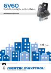
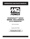
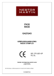
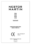
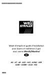
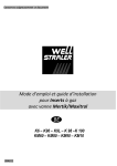
GV60 Remote Electronic Ignition and Control System OPERATING INSTRUCTIONS SPECIFICATIONS If the information in this manual is not followed exactly, a fire or explosion may result causing property damage, personal injury or loss of life. Gas combination control according to CSA or CE approval (see label). Fuels: CSA: Suitable for use with natural, manufactured, mixed and propane (LP) gases and LP gas-air mixtures. CE: Suitable for use with gases of EN 437 gas family 1, 2, 3. A. BEFORE OPERATING smell all around the appliance area for gas. Be sure to smell next to the floor because some gas is heavier than air and will settle on the floor. WHAT TO DO IF YOU SMELL GAS APPLICATION Do not try to light any appliance. Do not touch any electrical switch; do not use any phone in your building. Immediately call your gas supplier from a neighbor’s phone. Follow the gas supplier’s instructions. If you cannot reach your gas supplier, call the fire department. e-FLAME is a battery-powered electronic remote ignition and control system for gas appliances with pilot burners and ODS systems. OPERATING INSTRUCTIONS AUTOMATIC IGNITION B. Use only your hand to push in or turn the gas control knobs. Never use tools. If a knob will not push in or turn by hand, don’t try to repair it, call a qualified service technician. Force or attempted repair may result in a fire or explosion. When pilot ignition is confirmed, motor turns automatically to maximum flame height. Follow appliance manufacturer’s instructions for gaining accessibility to the gas control and the pilot. When turning main valve knob, do not force. Knob has a slipping clutch, allowing for manual main burner(s) flame height adjustment as well as adjustment to pilot stand by position (see figure 1). C. Do not use this control or any gas appliance if any part has been under water. Immediately call a qualified service technician to inspect the control or gas appliance to replace any part of the control system and any gas control which has been under water. MAN-Knob (optional) for Manual Ignition D. These instructions are to be referenced as a user guide, and do not supersede appliance manufacturer’s lighting instructions. Connection Piezo Igniter, Tab 2.8 x 0.8 mm Main Valve Knob Microswitch Piezo Igniter (optional) ON/OFF Switch (optional) Connection Pilot Gas 8 Wire Receiver Jack Figure 1: Combination Control GV60 1 Operating Instructions OPERATING INSTRUCTIONS MANUAL IGNITION OPTION 1. STOP! Read the safety information included before proceeding. (If equipped with optional MAN-Knob) 2. Turn main valve knob to the OFF, full clockwise position. Follow appliance manufacturer’s instructions for gaining access to the gas control and the pilot. 3. Place manual ON/OFF switch (if equipped) to the O (OFF position). When turning main valve knob, do not force. Knob has a slipping clutch, allowing for manual flame height adjustment as well as adjustment to pilot standby position. 4. Wait five (5) minutes to clear out any gas. Then smell for gas, including near the floor. If you smell gas STOP! Follow “A” in the safety information above. If you don’t smell gas, proceed to step 5. 1. STOP! Read the safety information included before proceeding. 5. Turn MAN-knob (if equipped) to the ON, full counterclockwise position (see figure 3). 6. Place manual ON/OFF switch in 2. Turn main valve knob to the OFF, full clockwise position. (ON position). 3. Turn MAN-knob (if equipped) to the MAN, full clockwise position. 7. Simultaneously press and hold the (star) and (up arrow) buttons (if Infrared Model: (star, up arrow) and the small lower button) until a short acoustic signal confirms the start sequence has begun; release buttons. Continuing signals confirms the ignition is in process. Once pilot ignition is confirmed there is main gas flow. (see figures 4 & 5) 4. Place manual ON/OFF switch (if equipped) to the O (OFF position). 5. Wait five (5) minutes to clear out any gas. Then smell for gas, including near the floor. If you smell gas STOP! Follow “A” in the safety information above. If you don’t smell gas, proceed to step 6. When pilot ignition is confirmed, motor turns automatically to maximum flame height. 6. Place manual ON/OFF switch in (ON position). 7. With the MAN-knob in MAN position a manual pilot valve operator is accessible (see figure 2). NOTE: If the pilot does not stay lit after several tries, turn the gas control knob (main valve knob) to OFF and proceed to step 9. Fully push down manual pilot valve operator and hold in, to start pilot gas flow. Immediately light the pilot with a match, while continuing to hold in the manual pilot valve operator for about one (1) minute after the pilot is lit. Release manual pilot valve operator. If pilot does not stay lit, repeat steps 2 through 8. 8. Set thermostat (if equipped) to desired setting or use remote control to adjust flame. In standby mode: press (up arrow) to increase flame height, press (down arrow) to decrease flame height or set appliance at pilot flame. For fine adjustment tap the up/down arrows. NOTE: If the pilot does not stay lit after several tries, turn the gas control knob (main valve knob) to OFF and proceed to step 11. 9. If the appliance will not operate, follow the instructions “TO TURN OFF GAS TO APPLIANCE” and call your service technician or gas supplier. 8. If applicable, per appliance manufacturer’s instructions, replace pilot access panel before proceeding. 9. Turn MAN-knob to the ON, full counterclockwise position. 2 Operating Instructions 10. Turn main valve knob to the full ON, full counterposition clockwise 4. Turn main valve knob to the OFF full clockwise position. 11. If the appliance will not operate, follow the instructions “TO TURN OFF GAS APPLIANCE” and call your service technician or gas supplier. 5. Replace appliance accessibility cover (if applicable), per appliance manufacturer’s instructions. NORMAL OPERATION A. IGNITION Simultaneously press and hold the ___(star) and (up arrow) buttons (if Infrared Model: (star, up arrow) and the small lower button) until a short acoustic signal confirms the start sequence has begun; release buttons. Continuing signals confirms the ignition is in process. Once pilot ignition is confirmed there is main gas flow. (see figures 4 & 5) Connection Piezo Igniter Tab 2,8 x 0,8 mm ON/OFF Switch (optional) In ON Position 8 Wire Receiver Jack MAN-Knob (optional) In MAN Position. When pilot ignition is confirmed, motor turns automatically to maximum flame height. Microswitch NOTE: If the pilot does not stay lit after several tries, turn the gas control knob (main valve knob) to OFF and proceed to step 3. Main Valve Knob In ON Position B. ADJUSTMENT - FLAME HEIGHT 1. Set thermostat (if equipped) to desired setting or use remote control to adjust flame. In standby mode: press (up arrow) to increase flame height, press (down arrow) to decrease flame height or set appliance at pilot flame (see figure 4). For fine adjustment tap the up/down arrows. Figure 2: Combination Control, Cover Cutout for Pilot Gas Adjustment MAN-Knob (optional) In Position for Automatic Ignition. Figure 4: Remote Handset, Standard Model Figure 3: Combination Control, View MAN-Knob (optional) 2. If the appliance will not operate, follow the instructions “TO TURN OFF GAS TO APPLIANCE” and call your service technician or gas supplier. TO TURN OFF GAS TO APPLIANCE 1. Press OFF button on remote (if available). 2. Follow appliance manufacturer’s instructions for gaining accessibility to the gas control. 3. Place manual ON/OFF switch in O (off position). 3 Operating Instructions C. ADJUSTMENT - FLAME HEIGHT INFRARED MODEL GENERAL NOTES A code is preset for all Mertik Maxitrol electronics, but can be changed if required. If you wish to change the code, complete the following: To increase flame height press simultaneously ___ (star, up arrow) and the small lower button. There is a separate button left for switching off (see figure 5). 1. Change DIP switch position (see figure 6). Figure 6: DIP Switch in Remote Handset Battery Compartment Figure 5: Remote Handset, Infrared Model 2. NOTE: (Thermostatic Models) To save battery power, press (down arrow) to turn main gas to pilot gas. Press OFF button to shut off the device including pilot flame. The device can be shut off with the ON/OFF switch, thus disabling the remote handset. Press and hold the receiver’s reset button until you hear two (2) acoustic signals. After the second longer acoustic signal, release the reset button and within the subsequent 20 seconds, press the (down arrow) on the remote handset until you hear an additional long acoustic signal confirming the new code is set (see figure 7). BATTERY REPLACEMENT Battery replacement is recommended at the beginning of each heating season. Batteries need to be changed when an acoustic error message is heard. Do not use metallic tooling. Metallic tooling could cause a short that may render the receiver inoperable. Reset Figure 7: Receiver with Reset button Receiver: ...................... 4 x 1.5V “AA” (quality alkaline recommended) Location of Receiver When the RF-receiver is placed in the appliance, the surrounding metal can reduce reception considerably. The position of the antenna on the receiver also influences reception. The antenna must not come in contact or cross the ignition wire. Remote Handset: ......... 1 x 9V (quality alkaline recommended) An AC Mains Adapter may be used instead of batteries (only the Mertik Maxitrol or an approved AC Mains Adapter can be used). Automatic Pilot Mode with Thermostat Remote NOTE: During a power outage the AC Mains Adapter must be unplugged from the receiver to operate in the battery mode. If there is no transmission from the handset to the receiver within a 6 hour time period, the appliance will go to standby (pilot) mode. Maxitrol Company 23555 Telegraph Rd., Southfield, MI 48037 www.mertikmaxitrol.com Copyright © 2005 Maxitrol Company All Rights Reserved GV60-OI-EN-04.2006 4