1
ALPINES II
OPERATOR'S MANUAL
414
model
V.I.N.
purchase date
warranty expiry date
To be completed by dealer at time of sale
DEALER IMPRINT AREA
AFTER SALES SERVICE
BOMBARDIER INC.
VALCOURT (QUEBEC)
CANADA
JOE 2LO
Litho'd in Canada
The following are trademarks of Bombardier Inc.
ALPINE®
BOMBARDIER®
ELAN®
®*Trademarks of Bombardier Inc.
FORMULA*
NORDIK®
ROTAX®
SKI-DOO®
All rights reserved e Bombardier Inc.
FOREWORD ____________________
The operator manual and the Snowmobile Safety Handbook have been prepared to acquaint the owner I operator
or passenger of a new snowmobile with
the various vehicle controls, maintenance and safe operating instructions.
Each is indispensable for the proper use
of the product, and should be kept with
the vehicle at all times.
Should you have any questions pertaining to the warranty and its application,
please consult the "Often Asked Question" section of this manual, or your authorized dealer.
This manual uses the following symbols.
WARNING: Identifies an instruction which, if not followed, could
•
cause serious personal injuries including possibility of death.
,.,. CAUTION : Denotes an instrucT tion which, if not followed, could
severely damage vehicle components.
0
NOTE : Indicates supplementary
information needed to fully complete an instruction.
Although the mere reading of such information does not eliminate the hazard,
your understanding of the information
will promote its correct use .
WARNING :The engines and the
corresponding components iden•
tified in this manual should not be utilized on product(s) other than those
mentioned on the cover page of this
manual.
WARNING: Maintenance procedures and tightening torques must
•
be strictly adhered to, never attempt
repairs unless the appropriate tools
are available.
The information and components I system descriptions contained in this manual are correct at time of publication.
Bombardier Inc. however, maintains a
policy of continuous improvement of its
products without imposing upon itself
any obligation to install them on products previously manufactured.
Bombardier Inc. reserves the right at any
time to discontinue or change specifications, designs, features, models or
equipment without incurring obligation.
The illustrations show the typical construction of the different assemblies and,
in all cases, may not reproduce the full
detail or exact shape of the parts shown,
however, they represent parts which
have the same or a similar function.
Most specifications are given in both
metric and customary units. Where precise accuracy is not required, some conversions are rounded to even numbers
for easier use.
A shop manual can be obtained for complete service, maintenance and repair information.
,.,. CAUTION : Most components of
T this vehicle are built with parts
dimensioned in the metric system.
Most fasteners are metric and must
not be replaced by customary fasteners or vice versa. Mismatched or incorrect fasteners could cause damage
to the vehicle or possible personal injury.
TABLE OF CONTENTS _ _ _ _ __
SAFETY MEASURES ...... .
5
THE 1990 "LIMITED WARRANTY".
HOW TO IDENTIFY YOUR SNOWMOBILE
6
8
10
11
CONTROLS/INSTRUMENTS..
. ....... .
12
Throttle lever
Brake lever
Parking brake lever
Ignition switch
Headlamp dimmer switch
Emergency cutout switch
Rewind starter handle
Primer
Adjustable steering handle
Gear shift lever
Speedometer
Trip meter reset button
High beam pilot lamp
Hood opening
Console
Fuel gauge/tank cap
Seat compartment
Fuse holder
Hitch
Accessories
OFTEN ASKED QUESTIONS ...... .
LISTING OF AREA DISTRIBUTORS.
BREAK-IN PERIOD .
Engine and belt break-in
10 hour-inspection
18
Break-in fuel/ oil mixing charts
Inspection check list
FUEL & OIL.
Recommended fuel
Recommended oil
Fuel mixture ratio
21
Fuel mixing procedure
Fuel I oil mixing charts
24
PRE-START CHECK
Check points
24
STARTING PROCEDURE.
Manual starting
Electric starting
Before riding
Emergency starting
3
LUBRICATION . . . . . . . . . . . . . . . . . . . . . . . . . . . . . . . . . . . . . . . . . . .
Frequency
Steering mechanism
Drive axles
Driven pulley
Slide suspension
Hitch sliding action
Gearbox oil level
MAINTENANCE
Chart
Belt guard removal
Drive belt removal and installation
Drive belt condition
New drive belt
Brake condition
Brake adjustment
Spark plugs
Battery
Suspension condition
Stopper strap condition
Suspension adjustment
Track condition
Track tension and alignment
31
Drive pulley
Steering mechanism
Steering adjustment
Muffler attachment
Engine head nuts
Engine mount nuts
Carburetor adjustment
High altitude kit
Fan belt
Drive chain tension
Headlamp beam aiming
Bulb replacement
General inspection
STORAGE
Tracks
Suspension
Ski
Controls
Gearbox
Drive pulley
26
44
Engine
Fuel tank and carburetor
Battery
Chassis
General inspection
Suspension stopper strap
PRE-SEASON PREPARATION . . . . . . . . . . . . . . . . . . . . . . . . . . . . . .
48
Pre-season preparation chart
TROUBLE SHOOTING . . . . . . . . . . . . . . . . . . . . . . . . . . . . . . . . . . . .
49
TOOLS . . . . . . . . . . . . . . . . . . . . . . . . . . . . . . . . . . . . . . . . . . . . . . . . .
52
SPECIFICATIONS ......................... .
53
Sl METRIC INFORMATION GUIDE . . . . . . . .
55
4 ----------------------------
SAFETY
MEASURES ____________________________
Observe the following
precautions :
• Throttle mechanism should be checked for free movement before starting
engine.
• Do not operate vehicle near snow
making equipment.
• Engine should be running only when
belt guard and I or pulley guard is secured in place.
• Never run the engine without drive
belt installed. Running an unloaded
engine can prove to be dangerous.
• Never run the engine when the track
is raised off the ground.
• It can be dangerous to run engine
with the hood removed.
• Gasoline is flammable and explosive
under certain conditions. Always manipulate in a well ventilated area. Do
not smoke or allow open flames or
sparks in the vicinity. If gasoline fumes
are noticed while driving, the cause
should be determined and corrected
without delay.
• Maintain your vehicle in top mechanical condition at all times.
• Your snowmobile is not designed to
be driven or operated on black top,
bare earth, ice, hard pack or other
abrasive surfaces. On such surfaces
abnormal and excessive wear of critical parts is inevitable.
• Your snowmobile is not designed to
be operated on public streets, road
or highways. In most States and Provinces, it is considered an illegal operation.
• Installation of other than standard
equipment, including ski-spreaders,
bumpers, pack racks, etc., could severely affect the stability and safety
of your vehicle. Avoid adding on accessories that alter the basic vehicle
configuration.
• The snowmobile engine can be stopped by activating the emergency cutout switch, tether switch or by turning off the key.
• Whenever the vehicle is parked outdoors, overnight or for a long period,
it is suggested to protect it against
the inclemency of the weather with
a snowmobile cover.
• Do not lubricate throttle and I or brake
cables and housings.
• Only perform procedures as detailed
in this manual. Unless otherwise specified, engine should be turned OFF
for all lubrication and maintenance
procedures.
• Clean and check operation of the
headlight, taillight and brake light.
• These vehicles are designed for the
driver only. No provisions have been
made for a passenger.
• Should removal of a locking device
be required when undergoing repairs/
disassembly, always replace by new
ones. Tighten fasteners as specified
in the applicable Shop Manual.
PLEASE READ AND UNDERSTAND ALL WARNINGS AND CAUTIONS IN THE
SNOWMOBILER'S SAFETY HANDBOOK, THE OPERATOR'S MANUAL AND ON
THE VEHICLE
BOTH MANUALS SHOULD REMAIN WITH THE VEHICLE
AT THE TIME OF RESALE
5
THE 1990 SNOWMOBILE
LIMITED WARRANTY _ _ _ _ _ _ _ _ __
1 -PERIOD
BOMBARDIER INC. as manufacturer, warrants FROM THE DATE OF DELIVERY TO THE
FIRST CONSUMER, every 1990 BOMBARDIER® snowmobile, sold as NEW AND UNUSED,
and predelivered by an authorized BOMBARDIER® dealer for a period of:
• 12 consecutive months.
• Warranty coverage on all new snowmobiles delivered between August ·1st and
December 1st of a year will expire on December 1st of the following year.
2- WHAT BOMBARDIER INC. WILL DO
BOMBARD lEA INC. will repair and I or replace, at its option, components defective
in material and I or workmanship (under normal use and service), with a genuine
BOMBARD lEA® component without charge for parts or labour, at any authorized
BOMBARDIER® dealer during said warranty period.
3- CONDITION TO HAVE WARRANTY WORK PERFORMED
Present to the servicing dealer, the hard copy of the BOMBARDIER® Warranty Registration
card or proof of purchase received by the customer from the selling dealer at time of
delivery.
4 - EXCLUSIONS - ARE NOT WARRANTED
• Normal wear on all items such as, but not limited to :
drive belts
- slider shoes
spark plugs
bulbs
runners on skis
• Replacement parts and/or accessories which are not genuine BOMBARDIER® parts
and I or accessories.
• Damage resulting from installation of parts other than genuine BOMBARD lEA® parts.
• Damage caused by failure to provide proper maintenance as detailed in the Operator's
Manual. The labour, parts and lubricants costs of all maintenance services, including
tune-ups and adjustments will be charged to the owner.
• Cold seizure and piston scuffing caused by insufficient warm-up.
• Vehicles designed and I or used for racing purposes.
• All optional accessories installed on the vehicle. (The normal warranty policy for parts
and accessories, if any, applies).
• Damage resulting from accident, fire or other casualty, misuse, abuse or neglect.
• Damage resulting from operation of the snowmobile on surfaces other than snow.
• Damage resulting from modification to the snowmobile not approved in writing by
BOMBARDIER INC.
• Damage incurred by track studs.
• Losses incurred by the snowmobile owner other than parts and labour, such as, but
not limited to, transportation, towing, telephone calls, taxis, or any other incidental
or consequential damage.
6
5- BATTERY WARRANTY:
•
12 consecutive months (Pro-rated).
100% warranty coverage will start on the date the snowmobile was delivered and
run to the following April 30th. The remainder of the 12 month-period will be prorated as follows :
- 50% from April 30th to December 1st.
- 40% from December 1st to December 31st.
30o/o from January 1st to end of warranty.
6 - EXPRESSED OR IMPLIED WARRANTIES
This warranty gives you specific rights and you may also have other legal rights
which may vary from state to state, or province to province. Where applicable
this warranty is expressly in lieu of all other expressed or implied warranties of
BOMBARDIER INC., its distributors and the selling dealer, including any warranty of merchantability or fitness for any particular purpose; otherwise the implied warranty is limited to the duration of this warranty. However, some states
or provinces do not allow limitations on how long an implied warranty lasts, so
the above limitation may not apply.
Neither the distributor, the selling dealer, nor any other person has been authorized to make any affirmation, representation or warranty other than those contained in this warranty, and if made, such affirmation, representation or warranty
shall not be enforceable against BOMBARDIER INC. or any other person.
Some states or provinces do not allow the exclusion or limitation of incidental
or consequential damages, so the above limitation or exclusion may not apply.
BOMBARDIER INC. reserves the right to modify its warranty policy at any time,
being understood that such modification will not alter the warranty conditions
applicable to vehicles sold while the above warranty is in effect.
7- CONSUMER ASSISTANCE
If a servicing problem or other difficulty occurs, we suggest the following :
1. Try to solve the problem at the dealership with the Service Manager or Owner.
2. If this fails, contact your area distributor listed in the Operator's Manual.
3. Then if your grievance still remains unsolved, you may write to us :
Bombardier Inc.
Service Department
Snowmobile Division
Valcourt, Quebec, Canada JOE 2LO
September 1988
Bombardier Inc.
Valcourt, Quebec, Canada JOE 2LO
®*Trademarks of Bombardier Inc.
7
OFTEN ASKED
QUESTIONS ___________________________
0 : Why must my snowmobile be registered at the factory ? After all I do have my
original invoice as proof of when I purchased my snowmobile.
A : Your warranty is valid at any authorized dealer of the product. Your registration
is the key elemen( in providing the servicing dealer with the necessary data to
complete warranty claim forms. This information is also used to notify owners
in the event of a safety recall.
0: Who should send the registration card to Bombardier Inc. 7
A : The dealer. However, it is important that the customer make sure that it has
been sent. The company might contact you should your vehicle be recalled
or in case of a particular warranty campaign.
0: I bought my snowmobile in O'King County but I snowmobile in Washington
County. Can the dealer in Washington County accept to perform warranty work
on my snowmobile?
A : Yes, any authorized dealer in North America can perform warranty repairs,
providing the customer warranty registration card is presented.
0 : Where can I find information on the lubrication and maintenance of my snowmobile?
A : In this Operator Manual provided with the vehicle at the time of delivery.
0: Will the entire warranty be void or cancelled, if I do not operate or maintain my
new snowmobile exactly as specified in the Operata( s Manual ?
A : The warranty of the new snowmobile cannot be "Voided" or "Cancelled'~
However, if a particular failure is caused by operation or maintenance other than
is shown in the Operator Manual, THAT fatlure may not be covered under warranty. This includes service work performed by the customer, especially the
critical adjustments to ignition, timing, carburation and oil injection I or oil
mixture.
0 : Would you give some examples of abnormal use or strain, neglect or abuse?
A : These terms are general and overlap each other in areas. Some specific examples may include : running the machine out of oil, chain fatlure caused by a
lack of lubrication, operating the machine with a broken or damaged part which
causes another part to fail, and so on. If you have any specific questions on
operation or maintenance, please contact your dealer for advice.
8
0: What costs are my responsibility during the warranty period?
A : The customer's responsibility includes all costs of normal maintenance sernon-warranty repairs, accidents and collision damage, as well as oils,
and spark plugs, and incidental or consequential damages costs as explained
in the warranty.
0: Are ''Genuine" Bombardier replacement parts used in warranty repairs covered
by warranty?
A : Yes. When installed by an authorized dealer, any "Genuine" Bombardier part
used in warranty repairs assumes the remaining warranty that exists on the
machine.
0 : If I sell my snowmobile within the warranty period, will the new owner qualify
for the balance of the warranty ?
A : Yes, provided the unit has already been registered with the manufacturer.
Note that the change of ownership card in this manual should be completed
and sent to Bombardier Inc.
0 : How can I receive the best owner assistance ?
A : The satisfaction and goodwill of the owners of Bombardier products are of
primary concern to your dealer and Bombardier Inc. Normally, any problems
that arise in connection with the sales transaction or the operation of your snowmobile will be handled by your Dealers Sales or Service Departments. It is recognized, however, that despite the best intentions of everyone concerned, misunderstandings will sometimes occur. If you have a problem that has not been
handled to your satisfaction through normal channels, we suggest that you discuss your problem with a member of dealership management. Frequently, complaints are the result of a breakdown in communications and can quickly be
resolved by a member of the dealership management. If the problem already
has been reviewed with the Sales Manager or Service Manager, contact the
Dealer himself or the General Manager.
9
LISTING OF AREA
DISTRIBUTORS _ _ _ _ _ _ _ _ _ _ __
CANADIAN DISTRIBUTORS
AMERICAN DISTRIBUTORS
PROVINCE OF QUEBEC
EAST-CENTRAL, CENTRAL,
WESTERN REG ION
SERVICE OFFICE
SALES OFFICE
BOMBARDIER INC.
Valcourt (Quebec) JOE 2LO
(514) 532-2211
BOMBARDIER CORPORATION
7575 Packer Drive
P.O. Box 8035
Wausau, Wisconsin 54402-8035
SALES OFFICE
BOMBARDIER INC.
1350 Nobel Street
Boucherville {Quebec)
(514) 655-6121
U.S.A.
J4B 1A1
EAST-CENTRAL, CENTRAL REGION
SERVICE OFFICE
PROVINCE OF ONTARIO
SERVICE AND SALES OFFICE
BOMBARDIER INC.
230 Bayview Drive
Barrie (Ontario) L4N 5E9
(705) 728-8600
(218) 628-2881
WESTERN REGION
SERVICE OFFICE
BOMBARDIER INC.
P.O. Box 7060
Riverview (New Brunswick)
(506) 386-6117
SERVICE OFFICE
E1B 1VO
SALES OFFICE
BOMBARDIER CORPORATION
P.O. Box 1572
Golden, Colorado 80402-1572
U.S.A.
{303) 232-5284
EASTERN REG ION
J4B 1A1
SERVICE AND SALES OFFICE
ALBERTA, BRITISH COLUMBIA, MANITOBA,
SASKATCHEWAN, YUKON
SERVICE AND SALES OFFICE
BROOKS EQUIPMENT LIMITED
1616 King Edward Street
P.O. Box 985
Winnipeg (Manitoba) R3C 2V8
(204) 633-7247
NEWFOUNDLAND, LABRADOR
SERVICE AND SALES OFFICE
CHARLES R. BELL LIMITED
Riverside Drive
P.O. Box 1050
Corner Brook (Newfoundland)
(709) 634-3533
BOMBARDIER CORPORATION
East Main Street Road
Malone, New York 12953
U.S.A.
(518) 483-4411
ALASKA
SERVICE AND SALES OFFICE
THE BRYANT CORPORATION
NE. 190th & Woodinville
Snohomish Road
P.O. Box 389
Woodinville, Wa 98072
U.S.A.
(206) 482-0110
A2H 6J7
NORTH-WEST TERRITORIES,
FRANKLIN DISTRICT & KEEWATIN
SERVICE AND SALES OFFICE
HUDSON'S BAY CO. LIMITED
165 Hymus Blvd
Pointe-Claire (Quebec) H9R 1G2
(514) 630-5279
10
BOMBARDIER CORPORATION
4505 West Superior Street
P.O. Box 16106
Duluth, Minnesota 55816-0106
U.S.A.
ATLANTIC REG ION
BOMBARDIER INC.
1350 Nobel Street
Boucherville (Quebec)
( 514) 655-6121
(715) 842-8886
HOW TO IDENTIFY
YOUR SNOWMOBILE _ _ _ _ _ _ _ _ __
The main components of your snowmobile (engine/ track and frame} are identified
by different serial numbers. It may sometimes become necessary to locate these
numbers for warranty purposes or to trace your snowmobile in the event of loss.
Engine serial
number
Track
serial number
A009 005 002
A017 005 012
0
NOTE :We strongly recommend that you take note of all the serial numbers
on your vehicle and supply them to your insurance company. It will surely
help in the event your snowmobile is stolen.
11
CONTROLS/INSTRUMENTS _ _ __
E
M
J
F
c
A
0
H
A017 007 016
A)
8 )
C)
D)
E)
F)
G)
H)
Throttle lever
Brake lever
Parking brake lever
Ignition switch
Head/amp dimmer switch
Emergency cut-out switch
Tether cut-out switch
Rewind starter handle
I )
J )
K)
L )
M)
N)
Primer
Adjustable steering handle
Gear shift lever
Speedometer
Trip meter reset button
High beam pilot lamp
0 ) Hood opening
P) Console
A) Throttle Lever
B) Brake Lever
Located on the right side of handlebar.
When compressed, it controls the engine speed and the engagement of the
transmission. When released, engine
speed returns automatically to idle.
Located on the left side of handlebar.
When compressed, the brake is applied.
When released, it automatically returns
to its original position. Braking effect is
proportionate to the pressure applied on
the lever and to the type of terrain and
its snow coverage.
12
C) Parking Brake Lever
E) Headlamp Dimmer Switch
Located on right side of handlebar. To
engage parking brake, squeeze lever and
turn lock
turn lock clockwise. To
counterclockwise.
Two position switch/ located on left side
of handlebar. to obtain high or low
beam simply flick switch.
Lock
AOOB 006 003
F) Emergency Cut-Out Switch
A009 006 001
D) Ignition Switch
OFF
A push pull type switch located on the
right side of the handlebar. To stop the
engine in an emergency, push the button to the lower off position and simultaneously apply the brakes. To start engine/ button must be at the upper on position.
A002 007 002
Key operated, 3 position switch. To start
engine, turn key to START position and
hold. Return key to ON position immediately when engine has started. To stop
engine, turn key to OFF position. If engine does not start on first try/ key must
be turned fully back to OFF each time.
.... CAUTION : Holding key in START
-,.. position when engine has started
could damage starter mechanism.
The lights are automatically ON whenever the engine is running.
A017 006 045
13
.A WARNING: For safety reasons,
T the emergency cut-out switch is
easily ~ccessible ; be careful not to
operate it inadvertently. If the switch
~as been used in an emergency situation the source of malfunction should
be determined and corrected before
restarting engine.
The driver of this vehicle should familiarize himself with the function of this
device by using it several times on first
outing. Thereby being mentally prepared
for emergency situations requiring its use.
J) Steering Handle
Steering handle height is adjustable/ see
your authorized dealer.
K) Gear Shift Lever
The gear shift lever is located right side
of the dashboard. It is a 3-position lever :
2 forward and 1 reverse. Pull lever upwards before selecting position.
G) Tether Cut-Out Switch
A pull switch located below the handlebar.
Attach tether cord to wrist or other convenient location then snap tether cut-out
c~p over receptacle before starting engine.
If emergency engine Shut off" is requi_red, comple~ely pull cap from safety
sw1tch and eng1ne power will automatically shut off.
11
0
NOTE :The cap must be installed
on the safety switch at all times in
order to operate the vehicle.
.A Y'fARNING : If the switch is used
T 1n an emergency situation the
source of malfunction should be determin~d and corrected before restarting
eng me.
H) Rewind Starter Handle
J:uto rewin~ type located ·On right hand
s1de of veh1cle. To engage mechanism,
pull handle/ slowly until a resistance is
felt then pull vigorously.
I) Primer
Pull and push button (2-3 times) to start
a .col~ engine. Not necessary when engme IS warm.
14 -------------------------
.A WARNING :This snowmobile is
T
capable of a fast reverse. Operator should become familiar with this
operation by practicing on level ground.
Always apply the brake before shifting and come to a complete stop then
while holding brake on, change gear:
Ensure the path behing is clear of obstacles or bystanders. Fast reverse
while turning, could result in loss of
stability.
L) Speedometer/Odometer/
Trip Meter
The speedometer indicates the speed of
the vehicle in kilometers per hour. Odometer records the total number of kilometers travelled. A trip meter is also combined with speedometer.
M) Trip Meter Reset Button
The trip meter button is located in dashboard right to speedometer. To reset,
turn button clockwise until all numbers
read zero.
A017 007 018
Raise and pull
rearward
N) High Beam Pilot Lamp
Lights up when headlamp is on high
beam.
0) Hood Opening
Pull down the latches to unlock the hood
from the anchors. Always lift hood gently up until stopped by restraining device.
.A. WARNING : It is dangerous to run
T an engine with the hood opened,
unfastened or removed.
A017 007 019
When installing console to vehicle/ ensure to insert console tabs into dashboard slots.
P) Console
Slots
To gain access to the engine, carburetor
and spark plugs, pull down the latch and
tip seat over from right, raise rear part
of console then pull rearward.
A017 007 021
Tabs
15
Fuel Gauge/Tank Cap
Under the hood, the fuel tank cap features a built-in needle fuel level gauge
which indicates the amount of fuel remaining in tank.
WARNING: Remove fuel tank
cap slowly. Fuel may be under
•
pressure and spray may cause fire and
injuries. Never use open flame to check
fuel level.
0
NOTE : Emergency materials should
be wrapped in foam or similar material. This will prevent possible damage
to breakable items when travailling over
rough or bumpy terrain.
Battery I Fuel Pump Compartment
Battery and fuel pump are located in
front portion of seat compartment.
WARNING: Do not store anything in the battery /fuel pump
•
compartment.
Fuse Holder
Starting system is protected with 30
amperes rated fuse. Fuse holder is located near starter and gearbox. If starter
does not operate, check fuse condition
and replace by the same rate if necessary.
Fuel gauge I tank cap
A017 002 012
Seat Compartment
Pull down the latch and tip seat. Ideal
location for spare spark plugs, belt, rope
etc.
Tip seat
Latch
A017 004 004
Fuse holder
Hitch
A hook-type hitch is provided to pull
most equipments. The hitch may be used
fixed or floating depending the type of
equipment towed. This allows smooth
operation when towing a load.
16
While towing a trailer with a fixed draw
bar, keep the hitch locked. With a floating draw bar, allow the hitch to move up
and down by removing its locking pin.
0
NOTE :To maintain the hitch locked, install the locking pin into hitch
post and place its flat side against the
hitch plate.
A hair pin is provided to lock the hook
of the hitch.
Remove for
floating use
A017 007 022
Hair pin
A017 007 022
WARNING :When towing any sled
or trailer, always ensure to lock
•
the hook type attachment with the
hair pin.
The locking pin can be installed into hair
pin when the hitch is used floating.
Locking pin ring
closed over hair pin
Trailers or sleds towed behing a snowmobile should always be loaded with the
lowest possible center of gravity. Use a
sled with a rigid draw bar. When pulling passengers in a tower vehicle, drive
at moderate speed and avoid rough terrain for their safety. Besides, have all
passengers get out of the towed vehicle and walk across all roads.
Accessories
Some optional accessories might be added to your vehicle such as horn, hourmeter, long seat with backrest, linen
cabin kit, tongue type hitch, etc. Ask
your authorized dealer for more information.
Hair pin
A017 007 024
17
BREAK-IN PERIOD _ _ _ _ _ __
Engine
With Bombardier-Rotax snowmobile engines, a break-in period is required before running the vehicle at full throttle.
Engine manufacturer recommendation
is 10 to 15 operating hours. During this
period, a richer mixture is needed (i.e.
40 parts of gas for 1 part of BUZZARD
oil). Maximum throttle should not exceed
3/4, however, brief full acceleration and
speed variations contribute to a good
break-in. Continued wide open throttle
accelerations, prolonged cruising speeds,
and engine over-heating are detrimental during the break-in period .
.,., CAUTION : Remove and clean
T spark plugs after engine break-in.
Belt
A new drive belt requires a break-in period of 25 km (15 miles).
1 0-Hour inspection
As with any precision piece of mechanical equipment, we suggest that after
the first 10 hours of operation or 30 days
after the purchase, whichever comes
first, that your vehicle be checked by
your authorized dealer. This inspection
will give you the opportunity to discuss
the unanswered quEstions you may have
encountered during the first hours of
operation.
The 10-hour inspection is at the expense of the vehicle owner.
18
Break-in Fuel/Oil Mixing
Charts
METRIC (SI)
-..r CAUTION :The following
chart
only applies to break-in period to
give a richer mixture of 40 to 1 ratio.
Sl UNITS
500 ml oil to 20 liters= 40:1
IMPERIAL UNITS
16 oz oil to 4.6 imp. gal= 40:1
or
500 ml oil to 4.8 imp. gal= 40:1
U.S. UNITS
16 oz oil to 5.1 U.S. gal= 40:1
or
500 ml oil to 5.3 U.S. gal= 40:1
T
FUEL
(liters)
250 300
100
400
500
OIL (ml}
IMPERIAL
24
16
8
32 35.2
OIL (imp. oz)
UNITED STATES
8
16
24
33.8
OIL (U.S. oz)
AOOO 000 018
19
10-HOUR INSPECTION CHECKLIST
.I
Engine timing
Fan belt tension
Spark plugs condition (Remove and clean)
Carburetor adjustment
Engine head nuts
Drive pulley screw (torque)
Engine mount nuts
Muffler attachment
Gearbox oil level
Drive chain tension
Battery electrolyte level
Brake operation and lining condition
Ski alignment (runner condition}
Handlebar bolts, retorque to 26 N•m (19 lbf•ft)
Pulley alignment and drive belt condition
Track condition, tension and alignment
Lubrication (steering, suspension, drive axles, etc.)
Electrical wiring, tighten all loose bolts, nuts and linkage
Operation of lighting system (HI /LO beam, brake light, etc.),
test operation of emergency cut-out switch and tether switch
We recommend that you have your dealer sign this inspection list.
Date of 10-hour inspection
20 ----------------------------
signature
FUEL & OIL _ _ _ _ _ _ _ __
Oil must be added to the fuel in
premeasured amounts then both oil and
fuel should be thoroughly mixed
together before fueling the tank.
Recommended fuel
Use regular leaded or unleaded gasoline
available from all service stations or gasohol with less than 10o/o of ethanol.
..A.. WARNING: Remove fuel tank
cap slowly. Fuel may be under
pressure and spray may cause fire and
injuries. Fuel is flammable and explosive under certain conditions. Always
manipulate in a well ventilated area.
Do not smoke or allow open flames or
sparks in the vicinity.
, . , CAUTION : Never experiment
T with other fuels or fuel ratios.
The use of fuel containing methanol,
or similar products including naphta is
not recommended. The use of unrecommended fuel can result in vehicle
performance deterioration and damage to critical parts in the fuel system
and engine components.
..A.. WARNING : Never "top up" the
fuel tank before placing the vehicle in a warm area. At certain temperatures, fuel will expand and overflow.
Always wipe off any fuel spillage from
the snowmobile.
T
T
Recommended oil
Use "BLIZZARD OIL:' (PIN 496 0135
00- 500 mU available from your dealer.
This type of oil will flow at temperatures
as low as -40°C (-40°F).
If "BLIZZARD OIL' is unavailable, substitute with "Bombardier injection oil"
(PIN 496 0133 00 - 1 liter or equivalent).
, . , CAUTION : Never use outboard
T or straight mineral oils.
Fuel mixture ratio
The importance of using the correct fuel
mixture cannot be overstressed. An incorrect fuel/ oil ratio results in serious
engine damage. Recommended fuel/ oil
ratio is 50:1 {40:1 during break-in period,
refer to ''break-in period', section for
mixing chart).
Sl UNITS
500 ml oil to 25 liters= 50:1
IMPERIAL UNITS
16 oz oil to 5 imp. gal= 50:1
or
500 ml oil to 5-1/2 imp. gal= 50:1
U.S. UNITS
13 oz oil to 5 U.S. gal= 50:1
or
500 ml oil to 6.6 U.S. gal= 50:1
NOTE :To facilitate gas mixing, oil
should be kept at room temperature.
0
Fuel mixing procedure
To mix the fuel and oil always use a
separate clean container. Never mix directly in your snowmobile tank.
21
+
WARNING: Fuel is flammable
and explosive under certain conditions. Always manipulate in a well
ventilated area. Do not smoke or allow open flames or sparks in the vicinity. If fuel fumes are noticed while
driving, the cause should be determined and corrected without delay.
Never add fuel while the engine is running. Avoid skin contact with fuel at
below freezing temperatures.
1. Pour approximately 4 liters (one gallon) of fuel into a clean container.
3. Replace the container cap and shake
the container thoroughly.
3&5
AOOO 000 005
4. Add the remainder of the fuel.
5. Once again thoroughly agitate the
container. Then using a funnel with a
fine mesh screen to prevent the entry
of foreign particles, pour the mixture
into the snowmobile tank.
AOOO 000 003
2. Add the amount of oil required for the
tota I mixture.
AOOOOOO 017
22
+
WARNING :To prevent fuel spillage in the engine compartment,
a funnel must always be used when
filling the gas tank.
NOTE : When using pre-mixed fuel,
always shake the container thoroughly as the oil has a tendency to settle.
0
FUEL/OIL MIXING CHARTS
(50 to 1 ratio)
METRIC (SI)
25 :::::::::::: ;:;: :::::::: ;:;: (
24 1-+--+-+--+-f---+-+-
2;3 t-+-++--t---1-t-t-+++-+
2;1
1--+-""1-t--+-1-t-
FUEL
19
18
17
16
15
14
(liters) 1213
11
10
8 9 1--+-""1-t--+-1---y-
6 7 1--+-""1-t---trl-t45
:1~~~
3
~
2,:::::::::::::::::::::::~:~::
50 100 150 200 250 300 350 400 450 500
OIL (mL)
IMPERIAL
4
FUEL
(imp. gal)
3
5 6.5
10
1516
OIL (imp. oz)
UNITED STATES
FUEL
(U.S. gal)
4
3
5
10
13
OIL (U.S. oz)
AOOO 000 006
23
PRE-START CHECK _ _ _ _ _ __
Check points
• Check fuel level.
• ACTIVATE THE THROTTLE CONTROL
LEVER SEVERAL TIMES to check
that it operates easily and smoothly.
The throttle control lever must return
to idle position when released.
• Verify that the path ahead of the vehicle is clear of bystanders and obstacles.
• Check that the ski and tracks are not
frozen to the ground or snow surface
and that the steering operates freely.
• Clean and check operation of the
headlight, taillight and brake light.
+
WARNING : Only start your snowmobile once all components are
checked and functioning properly.
• Activate the brake control lever and
make sure the brake fully applies before the brake control lever touches
the handlebar grip. It must fully return
when released.
STARTING PROCEDURE _ _ _ __
Test throttle control lever operation.
Check that the emergency cut-out switch
is in the upper ON position.
Activate the primer (two or three times).
A017 006 043
Ensure the tether cut-out cap is in position and that the cord is attached to your
clothing.
0
-.r
NOTE : Priming is not necessary
when the engine is warm.
CAUTION: Use of ether and/or
other types of fluid as a starting
aid can cause damage to engine components and is not recommended.
T
To start engine, follow either manual or
electric starting procedure.
24 -------------------------
Manual starting
Insert the key in the ignition and turn to
ON position.
Grasp manual starter handle firmly and
pull slowly until a resistance is felt then
pull vigorously. Slowly release the rewind starter handle.
WARNING :Do not apply throttle while starting.
+
Electric starting
Insert key in ignition switch.
,.,. CAUTION : Never operate your
T snowmobile with the battery removed or disconnected, since the battery reduces voltage fluctuations, operating vehicle without it might cause
instrument or bulb failure.
Turn ignition key clockwise until starter
engages. Release key immediately when
engine has started. If engine does not
start on first try, key must be turned fully back to OFF each time.
,.,. CAUTION : To avoid starter overT heating, the cranking period should
never exceed 30 seconds and a rest
period should be observed between
cranking cycles to let starter cool down.
WARNING: Do not apply throttle while starting.
NOTE : If for some reason, the vehicle cannot be started electrically,
+
+
WARNING : If engine does not
shut-off when flicking the emergency cut-out switch and I or by pulling the tether cut-out cap, stop the engine by turning OFF the ignition key.
Do not operate the vehicle, see your
authorized dealer.
Allow the engine to warm before operating at full throttle.
NOTE : Engine is warm when operating temperature has been reached
on temperature gauge. On vehicle without temperature gauge/ let engine idling
three to five minutes.
0
Emergency starting
Should the rewind starter rope fray and
break, the engine can be started with
the emergency starter rope supplied
with the tool kit.
Remove console to ease installation of
emergency rope around drive pulley and
crank the engine.
WARNING :Damage to console
or injury to the hand might be
experienced if the console is not removed.
WARNING : Do not wind starting
rope around your hand. Hold rope
by the handle only.
+
+
0
place ignition key to ON position and
start engine manually.
Before riding
Check operation of the emergency cutout switch and tether switch. Restart
engine.
A007 003 030
25
..&. WARNING :Do not start the veT hicle by the drive pulley unless it
is a true emergency situation. Have
the vehicle repaired as soon as possible.
Attach emergency rope to any available
handle and the starter clip supplied in the
tool box. Wind the rope thightly around
drive pulley.
NOTE : The spark plug socket can
be used as an emergency starter
grip.
0
Start engine as per usual manual starting.
Reinstall console but not belt guard .
..&. WARNING: When
starting the
vehicle in an emergency situation
by the drive pulley, do not reinstall the
belt guard.
T
LUBRICATION _ _ _ _ _ _ _ __
Frequency
~
AOOO 000 007
26
'
J.
~
Routine maintenance is necessary for all
mechanized products, and the snowmobile is no exception. A weekly vehicle inspection contributes to the life
span of the snowmobile.
It is recommended that the steering system and suspension be lubricated monthly or every 40 hours of operation. If the
vehicle is operated in wet snow or in
severe conditions these items should be
lubricated more frequently.
..A.. WARNING : Only
perform such
procedures as detailed in this
manual. It is recommended that dealer
assistance be periodically obtained on
other components/systems not covered in this manual. Unless otherwise
specified, engine should be turned OFF
for all lubrication and maintenance
procedures .
..A.. WARNING : Do not lubricate throttie and I or brake cables and housings.
When lubricating grease fitting, always
use low temperature grease (PIN 413
7061 00).
T
Remove the screw shown.
Grease fitting
T
Steering mechanism
Using light machine oil, lubricate the
longitudinal pivot of the ski and ski coupler bolt.
Lubricate until the grease appears from
the hole, then, firmly plug the hole with
a finger and slowly continue to lubricate
until grease appears at the joint.
Grease must
appear from
this joint
Oil tie rod ball joints and steering column
upper and lower bushings.
A017 006 007
Allow the oil to run in and move ski
several times to distribute lubricant.
From inside of cab, lubricate front shock
system as follows :
27
Drive axles
Driven pulley and brake discs
Two access plugs are located on each
side pan. Remove the front ones to get
access to drive axles grease fitting.
Driven pulley and brake discs must slide
freely on their shafts. See your authorized dealer.
Brake
disc
Driven
pulley
Lubricate using low temperature grease
then reinstall access plugs.
A017 003 064
Brake
disc
Front access
hole
A017 007 054
, . , CAUTION : Ensure to lubricate
T both drive axles. A grease fitting
is located on each side pan.
A017 003 065
Brake calipers
See your authorized dealer for proper lubrication of brake caliper ratchet wheel.
+
ings.
28
WARNING : Do not lubricate throttle and I or brake cables and hous-
Slide suspension
Lubricate the following parts at grease fittings until grease appears at joints. Use
low temperature grease only.
, . , CAUTION : Ensure to lubricate
T both suspension systems.
Front upper and lower cross shafts.
Rear cross shaft and both shafts of
shackle.
-Coat inside of stabilizer bar bushing
of rear suspension with grease.
Oil adjuster blocks cross shaft.
T
CAUTION : Lubricate every week.
RH adjuster
LH adjuster
block
block
Coat inside
of bushing
A017 005 015
A017 007 027
Cross shaft
29
Hitch sliding action
-Lubricate with low temperature
grease all around square tube.
To check level :
Remove rubber inspection cover located
on bottom right side of gearbox. Using
a rigid piece of wire as dipstick, check
oil level. Oil level must reach 92 mm
(3-5/8 in) on dipstick.
Gearbox
Filler
plug
Hood hinges
Oil both hinges.
To filii remove filler plug from top of gearbox. Refill as required using Bombardier
chaincase oil (P/N 413 8019 00 250
ml (9 oz)).
1
A017 007 085
Gearbox oil level
The gearbox oil capacity is 500 ml (18
oz).
30
MAINTENANCE ________________
The following Maintenance Chart indicates regular servicing schedules to be
performed by you or your authorized
dealer. If these services are performed
as suggested, your snowmobile will give
many years of use.
SERVICE AND
MAINTENANCE
CHART
+
WARNING: Only perform such
procedures as detailed in this
manual. It is recommended that dealer
assistance be periodically obtained on
other components I systems not covered in this manual. Unless otherwise
specified] engine should be turned OFF
for all lubrication and maintenance procedures .
.E
.E
0
0
>~E
-Q).:::t!
~~E
LO
~>o
Q.) CD
s .ON
.~
0
0
LO
..CQ,).:::t!
t:>o
0 Q,)
~s...O
000
~...
E
o.:::t:.
Q)
1...
0)
coo
Q) 0 :-::>N E
caM
>0
u ... O
cQ.)O
o>N
Q.)CD
co
a.
0
......
....
Q.)
"+Q,)
a:
NO)E : The 10-hour inspection is a very important part of proper service and
mamtenance.
31
Belt guard removal
A
WARNING :Engine should be
running only when belt guard is
secured in place.
T
1. Tilt the hood.
NOTE : The console may be removed to give an easier access if
desired.
0
2. Pull out both retaining pins.
A017 003 039
3. Slip slackened belt over the top edge
of the driven pulley sliding half, opposite side of gearbox.
Retaining pins
A017 003 038
3. Lift and remove the belt guard.
Drive belt removal and
installation
A
WARNING : Never start or run
engine without the drive belt installed. Running an unloaded engine
is dangerous.
1. Tilt hood and remove the belt guard.
2. Open the driven pulley by twisting
and pushing the sliding half. Hold in
fully open position.
T
4. Completely remove the belt from the
driven pulley and lie flat under the
driven pulley outside edge.
0
NOTE : Put on the parking brake
to facilitate the opening of driven
pulley.
Lie flat under
outside edge
A017 003 041
32
5. Slip belt out from the drive pulley and
remove completely from the vehicle.
To install the drive belt, reverse the procedure, however pay attention to the following:
The maximum .drive belt life span is obtained when the belt has the proper rotation direction. Install it so the printed
information on the belt can be read when
facing pulleys.
Drive belt condition
Inspect belt for cracks, fraying or abnormal wear (uneven wear, wear on one
side, missing cogs, cracked fabric). If
abnormal wear is noted, probable cause
could be pulley misalignment, excessive
A. P.M. with frozen track, fast starts without warmup period, burred or rusty
sheave, oil on belt or distorted spare
belt. Contact your dealer.
Check the drive belt width. Replace the
drive belt if width is less than 32 mm
(1-1/4 in).
New drive belt
When installing a new drive belt, breakin period of 25 km (15 miles) is strongly
recommended.
0
NOTE: Always store a spare belt
in a manner to allow its natural
shape to b'tl maintained.
Brake condition
The brake mechanism on your snowmobile is an essential safety device. Keep
this mechanism in proper working condition. Above all, do not operate your
snowmobile without an effective brake
system.
, . , CAUTION : Do not force or use
T tools to pry the belt into place,
as this could cut or break the cords in
the belt.
+
WARNING : Brake pads must be
replaced when fixed pad projects
only 1 mm (1/32 in) from caliper. Replacement must be performed by an
authorized dealer.
33
Spark plugs
Remove console to get access to spark
plugs. Disconnect wires then remove
spark plugs using socket supplied in tool
box.
Check the condition of the plugs.
• A brownish tip reflects ideal conditions. (Carburetor adjustments, spark
plug heat range, etc., are correct).
A008 003 015
Brake adjustment
If a quicker brake response is desired,
strongly squeeze the brake lever several times, this will actuate the self adjusting mechanism.
Strongly squeeze
• A black insulator tip indicates fouling
caused by : carburetor idle speed
mixture and I or high speed mixture
too rich, incorrect fuel mixture ratio,
wrong type of spark plug (heat range),
or excessive idling.
• A light grey insulator tip indicates a
lean mixture caused by: carburetor
high speed mixture adjusted too lean,
wrong spark plug heat range, incorrect fuel mixture ratio, or a leaking
seal or gasket.
Overheated
(light grey)
Fouled
(black)
A008 006 002
After the adjustment, brake should apply fully when lever is approximatively
13 mm (1/2 in) from handlebar grip. If
not, do not tamper with the brake, contact an authorized dealer.
13 mm {1/2 in)
,.,. CAUTION : If spark plug condi"Y tion is not ideal, contact your authorized dealer.
Check spark plug gap using a wire feeler gauge. It should be 0.4 mm (.016 in).
A008 006 002
34
Reinstall spark plugs and connect wires.
Reinstall console.
Battery
0
NOTE :The battery is located under the seat.
Check electrolyte level weekly. Electrolyte level must be at upper level line on
battery casing.
Maximum level
Minimum
~
!Ill . ......,..---
level~
A009 004 012
...&.. WARNING: Vent
tube must be
free and open. If not, it will restrict ventilation and create a gas accumulation that could result in an explosion. Avoid skin contact with electrolyte. Gases given off by a battery
being charged are highly explosive. Always charge in a well ventilated area.
Keep battery away from cigarettes or
open flames. Avoid skin contact with
electrolyte.
CAUTION : Prior to charging the
T battery, always remove it from
the vehicle to prevent electrolyte spillage. Be careful not to ground positive
terminal with the chassis. Always disconnect black negative cable first.
T
A009 004 011
Vent tube
If necessary add distilled water. Battery
connections must also be free of corrosion. If cleaning is necessary remove
corrosion using a stiff brush then clean
with a solution of baking soda and water.
Rinse and dry well.
...r CAUTION :Do not allow clean-
T ing solution to enter battery. It
will destroy the chemical properties of
the electrolyte.
After reconnecting battery/ coat battery
terminals and connectors with petroleum jelly to prevent corrosion. Check
that battery is well secured and that battery vent tube is not kinked or blocked.
...r
0
NOTE: Always keep battery fully
charged. (To charge, refer to ~~Bat
tery" in Storage" section).
II
35
Adjuster blocks
Use the key supplied in the seat compartment.
Suspension condition
Visually inspect all suspension components including slider shoes, springs,
wheels, suspension pivot etc.
NOTE : During normal driving,
snow will act as a lubricant and
coolant for the slider shoes. Extensive
riding on ice or sanded snow, will create excessive heat build-up and cause
premature slider shoe wear.
0
Stopper strap condition
A019 001 002
Inspect strap for wear and cracks, bolt
and nut for tightness. If loose inspect
holes for deformation. Replace as required. Torque nut to 10 N•m (89 lbf•in).
When the front adjuster blocks are at
the lowest elevation more weight is distributed to the ski thus giving a more
positive steering.
Suspension adjustment
+
WARNING :Always ensure to perform the same ajustments on
each rear suspension.
The rear suspension is adjustable for
surface condition and steering effects.
Besides the suspension rear pivot may
be adjusted depending the operator requirement.
I
Weight
on ski
Lowest
elevation
A017 005 018
Adjuster block
A017 005 019
At the highest position, the weight is
transferred to the track thus giving a
better traction to pull a load.
36 -------------------------
0
NOTE :When turning the external
adjuster block from one suspension/ the internal one of the same suspension will automatically turn at the
same time because they are linked together by a cross shaft.
,.,. CAUTION :Always turn adjuster
,.- block of the RH suspension in a
counterclockwise direction and the
one of the LH suspension, clockwise.
Both suspension must always be set
at the same elevation.
Suspension rear pivot
To prevent the rear portion of the track
from digging in the snow when in reverse, the slide suspension is hinged and
spring loaded. To check for correct preload/ measure the distance from the
outer edge of the pivot pin to the inner
edge of the adjustment bolt washer. The
distance should be 65 mm {2-9/16 in).
0
NOTE: The driver can customize
this adjustment to meet its particular need. For instance should one is
most of the time pulling a load and use
rarely the reverse, the rear pivot could
be /'locked" by fully tighten the adjustment bolt thus getting a better traction
and a more positive steering.
Stopper strap
The function of the suspension stopper
strap is to control the transfer of vehicle
weight during acceleration. The longer
the belt, the more the weight will be
transferred to the track, thus providing
a better traction. Adjusting holes in the
stopper strap allow to adjust to driver's
requirement, field and I or snow conditions.
For normal use, adjust the stopper to its
shorter length.
..A.. WARNING :Always torque the
nut to 10 N•m (89 lbf•in).
T
10 N•m (89 lbf•in)
A017 005 018
Pivot pin
A017 005 024
37
0
NOTE : For deep snow or hill climbing/ it is recommended to place
the front adjuster blocks on the lowest
position.
Track condition
Lift rear of vehicle and support it off the
ground. {Place gear shift lever in forward
position). With the engine OFF/ rotate
the track manually and inspect condition. If worn or cut, or if track fibers are
exposed, or if missing or defective inserts are noted; contact your authorized
dealer.
WARNING: Do not operate a
snowmobile with a cut, torn or
damaged track.
+
30 mm (1-3/16 in)
with 7.3 kg (16 lb)
A017 005 019
Track tension and
alignment
...r CAUTION: Too
WARNING :Always ensure to perform the same adjustments on
each rear suspension.
cessive stresses on suspension components.
+
Tension:
Lift the rear of vehicle and support with
a mechanical stand. The gap should be
30 mm (1-3/16 in) between the slider
shoe and the bottom inside of the track
when applying a downward pull of 7.3 kg
(16 lb). The gap should be measured
close to suspension center idler wheel.
If the track tension is too loose/ the track
will have a tendency to thump.
much tension
~ will result in power loss and ex-
If necessary to adjust; loosen the rear
idler wheel retaining screw and the adjuster bolt lock nut; then loosen or tighten the adjuster bolts located on the inner side of the rear idler wheels. If correct tension is unattainable, contact an
authorized dealer.
(TYPICAL)
Adjuster bolt
A023 005 002
38
0
NOTE : Track tension and alignment are inter-related. Do not adjust one without the other.
Tighten lock nuts and the idler wheel
retaining screws.
Alignment
Start the engine and accelerate slightly
so that track barely turns. This must be
done in a short period of time (one to
two minutes). Check that the track is
well centered ; equal distance on both
sides between edges of track guides
and slider shoes.
Guides~
Slider
shoes
A023 005 002
Restart engine, rotate track slowly and
recheck alignment.
A001 006 005
..A. WARNING : Before checking track
T alignment, ensure that the tracks
are free of all particles which could
be thrown out while track is rotating.
Keep hands, tools, feet and clothing
clear of track. Ensure no one is standing in close proximity to the vehicle.
To correct, stop the engine, loosen the
rear idler wheels retaining screws then
loosen the lock nuts and tighten the
adjuster bolt on side where the slider
shoe is the farthest from the track insert guides.
Guide
I
f
Guide
mm>.
Slider
shoes"'
Tighten on this side
A001 005 011
I
t
Drive pulley
This vehicle is equipped with the TRA
drive pulley (Total Range Adjustable).
The clutch is factory adjusted to provide
the best performance under most riding
conditions. However certain conditions,
such as deep snow, high altitude, pulling
a load, etc., may require a different adjustment. Contact the authorized dealer
for adjustment.
Steering mechanism
Inspect steering mechanism for tightness of components (steering arms, ball
joints, etc). If necessary, replace or retighten. Check longitudinal ski pivot free
movement, condition of ski and ski runners. Replace ski runners if worn.
..A. WARNING : Check the condition
T of the ski and the ski runners.
Replace if runners are more than half
worn.
39
Steering adjustment
Ski should be perpendicular to handle
bar. To align:
- Place ski parallel to vehicle.
Loosen lock nuts of the tie rod.
..A.. WARNING: The ball joint socket
T must run parallel with the steer-
ing arm and the other ball joint. The
socket must be restrained when tightening the tie rod end lock nuts.
A017 006 009
Turn tie rod manually until the handlebar is horizontal.
- Firmly retighten the lock nuts .
..A.. WARNING: The maximum ball
joint external threaded length not
engaged in the tie rod must not exceed 12 mm (15/32 in). Torque lock
nut to 20 N • m (15 lbf•ft).
T
Tighten
Muffler attachment
Torque to
20 N•m (15 lbf•ft)
A017 006 028
The engine I exhaust system parts are vital toward efficient muffler function.
Check all attachments and muffler ball
joint. Replace the springs and I or tighten
if necessary.
, . , CAUTION : Do not operate vehiT cle with muffler disconnected
otherwise serious engine damage will
occur.
Engine head nuts
With the ENGINE COLD, check that the
engine head nuts are tight and equally
torqued to 22 N •m (16 lbf•ft).
40
Respect tightening sequence as follows :
B) Idle speed adjustment
Turn the idle speed screw clockwise until a slight contact is felt then continue
turning two additional turns. This will
provide a preliminary idle speed setting.
Start engine and allow it to warm then
adjust the idle speed by turning the idle
speed screw clockwise or counterclockwise.
Idle speed: 1800-2000 RPM.
Fuel filter replacement
Remove fuel line grommet from top of
fuel tank and pull out inlet fuel line from
tank.
(Cylinder cowl removed)
A007 002 002
Position of
grommet when
installing
IMPORTANT : The engine head nut
torque should be checked after the
first 5 hours of operation.
Engine mount nuts
Check the engine mount nuts for tightness. Retighten if necessary to 38 N•m
(28 lbf•ft).
Carburetor adjustment
,... CAUTION : Never operate your
T snowmobile with the air intake
silencer disconnected. Serious engine
damage will occur if this notice is disregarded.
A) Air screw adjustment
Completely close the air screw (until a
slight seating resistance is felt) then
back off screw 1-1/2 turn.
A017 002 013
Replace fuel filter. To facilitate the fuel
line installation/ slide grommet on fuel
line about 50 mm (2 in) away from elbow than install grommet on fuel tank
and push down elbow through grommet.
A
A002 002 009
41
High altitude kit
Drive chain tension
Snowmobiles used in high altitude areas
(1200 m (4000 ft} and up) are subjected to lose power as temperature, elevation and snow condition are different.
The carburetor and power train have to
be recalibrated to meet those particular requirements. Ask your authorized
dealer for more information on high altitude kit availability.
, . , CAUTION : Do not change origiT nal jetting if using vehicle below
1200 m (4000 ft).
Run vehicle forward so that true free-play
can be taken. Check tension then turn
driven pulley 1/2 turn towards and recheck. Starting from maximum reading,
adjust chain tension to obtain 3-6 mm
(1/8-1/4 in) free-play.
Remove capscrew locking chain tensioner in place. (Tensioner is located at
bottom left of gearbox.)
Fan belt
Inspect belt for cracks, uneven wear,
etc. Check fan belt tension, 9-10 mm
(3/8 in) deflection should exist.
A017 003 031
Chain
tensioner
A009 002 019
If belt seems damaged or if tension is
incorrect, contact the dealer immediately.
A
T
WARNING: If fan protector is
removed, always reinstall after
servicing.
Cap
screw
A017 003 032
Rotate the tensioner as required to obtain correct chain tension.
Reinstall capscrew to lock chain tensioner in place.
42
Headlamp beam aiming
General inspection
To adjust, remove the four caps, turn upper or lower adjusting screws to obtain
desired beam position.
Check electrical wiring and components/
retighten loose connections. Check for
stripped wires or damaged insulation.
Thoroughly inspect the vehicle and tighten loose bolts, nuts and linkage.
.A. WARNING : Check the condition
of the ski and the ski runners.
Replace if runners are more than half
worn.
_ _ _ _ _ Adjusting
screw - - - - - - ,
T
A007
,___ _ _ Adjusting _ _ ___.
oo4 oo2
screw
Bulb replacement
If headlamp is burnt, tilt hood. Unplug
connector from headlamp. Remove rubber boot and unfasten bulb retainer clips.
Detach bulb and replace.
If taillight bulb is burnt, remove the red
plastic lens and replace bulb.
.A. WARNING :Always check light
T operation after bulb replacement.
43
STORAGE ____________________
It is during summer, or when a vehicle
is not in use for any length of time that
proper storage is a necessity. Storage of
the snowmobile during long periods of
inactivity consists of checking and replacing missing, broken or worn parts,
proper lubrication and treatment to insure that parts do not become rusted ;
cleaning items such as carburetor of oil
mixture, to prevent gum and varnish formation within the carburetor, and in general, preparing the vehicle so that when
the time comes to use the snowmobile
again it will be in top condition.
A
WARNING : Only perform such
procedures as detailed in this
manual. It is recommended that dealer
assistance be periodically obtained on
other components I systems not covered in this manual. Unless otherwise
specified, engine should be turned OFF
for all lubrication and maintenance
procedures.
T
Tracks
Inspect tracks for wear, cuts, missing
track guides or broken rods. Make any
necessary replacement.
A
T
WARNING :Do not operate a
snowmobile with a cut, torn or
damaged track.
Ski and runner
Wash or brush all dirt or rust accumulation from the ski. Lubricate ski longitunal pivot.
A
T
WARNING :Check the condition
of the ski and ski runners. Replace runner if worn more than half.
Controls
Lubricate steering mechanism. Inspect
components for tightness (spring coupler bolt, steering arm locking bolts, ball
joints, etc.}. Tighten if necessary. Oil
moving joints of the brake mechanism.
A
T
WARNING :Do not lubricate throttie and I or brake cable or housings. Avoid getting oil on the brake
linings.
Coat electrical connections and switches
with silicone dielectric grease (PIN 413
7017 00). If unavailable, use petroleum
jelly.
Gearbox
Drain gearbox and refill with 500 mL
(18 oz) of fresh Bombardier chaincase
oil (P/N 413 8019 00-250 mU. The
drain plug is located underneath the
front part of the vehicle.
Lift the rear of vehicle until track is clear
of ground, then support with a brace or
trestle. The snowmobile should be stored
in such a way that the tracks do not stay
in contact with cement floor or bare
ground.
NOTE : The tracks should be rotated periodically, (every 40 days).
Do not release track tension.
0
, . , CAUTION : To prevent track damT age, temperature in the storage
area must not exceed 38°C (100°F).
Suspension
Remove any dirt or rust. Grease all components equipped with grease fittings.
Wipe off surplus. Replace worn slider
shoes.
44
Drain plug
A017 003 042
Drive pulley
7. Restart engine and run at idle.
Inspection and cleaning must be performed by an authorized dealer at the
end of each season.
8. Inject storage oil until the engine dies
or until a sufficient quantity of oil has
entered the engine (approximately
30 seconds).
9. With the engine stopped, remove the
spark plugs and pour approximately
85 ml (3 imp oz) of Bombardier oil
into each cylinder.
10. Crank slowly two or three revolutions to lubricate cylinders.
11 . Reinstall the spark plus and the outlet primer hose.
Do not run engine during storage period.
Engine
Engine internal parts must be lubricated to protect them from possible rust
formation during the storage period.
To perform the storage procedures proceed as follows:
1. Lift the rear of the vehicle and support it off the ground .
..A. WARNING : Ensure the tracks are
T free of all particles which could
be thrown out while it is rotating. Keep
hands, tools, feet and clothing clear
of tracks. Ensure no one is standing
in close proximity to the vehicle.
2. Start the engine and allow it to run
at idle speed until the engine reaches
its operational temperature.
3. Stop the engine.
4. To prevent gasoline from draining,
primer button should be pushed all
the way.
5. Disconnect the outlet primer hose
from the primer valve.
(Oblique
coupling}
A017 002 014
Fuel tank and carburetor
Remove the cap then, using a syphon,
remove the gasoline from tank.
..A. WARNING :Gasoline is flammaT ble and explosive under certain
conditions. Always manipulate in a
well ventilated area. Do not smoke or
allow open flames or sparks in the vicinity.
The carburetor must be dried out completely to prevent gum formation during
the storage period.
Once the fuel tank is emptied, remove
the float chamber drain plug from carburetor. Drain carburetor and reinstall
plug.
(Straight
coupling}
6. Insert storage oil (PIN 496 0141 00)
can hose into primer outlet hose.
Plug
A002 002 010
Check all fuel lines, replace if necessary.
45
Battery
0
NOTE : The battery is located in
the seat compartment.
The battery should be removed from vehicle when storing vehicle.
To remove, proceed as follows :
1. Disconnect the battery cables and remove the battery retainer cover.
~CAUTION : To avoid possibility of
T grounding the positive terminal
with the chassis, always disconnect
black negative lead first.
Check electrolyte level. Refill as necessary with distilled water. Fully charge
battery at a maximum rate of 2.0 amps.
~CAUTION : Prior to charging the
T battery, always remove it from
the vehicle to prevent electrolyte spillage.
..A.. WARNING :Gases given off by a
battery being charged are highly
explosive. Always charge in a well
ventilated area. Keep battery away
from cigarettes or open flames. Avoid
skin contact with electrolyte.
NOTE : To prevent battery from
discharging, store it on a wooden
shelf in a cool, dry place. Recharged at
least every 40 days.
T
0
Chassis
+
A017 004 012
Red lead
2. Disconnect vent tube.
3. Lift out the battery. Before storing the
battery, clean outside surface with a
solution of baking soda and water.
Remove all deposits from posts then
rinse with clear tap water.
~CAUTION
: Do not allow cleaning solution to enter battery interior since it will destroy the electrolyte.
T
46
Clean the vehicle thoroughly, removing
all dirt and grease accumulation.
~CAUTION : Plastic alloy com poT nents such as fuel tank, windshield, controls, etc., can be cleaned
using mild detergents or isopropyl alcohol and a soft clean cloth. Never
clean plastic parts with strong detergent, degreasing agent, paint thinner,
acetone, etc. Do not apply isopropyl
alcohol directly on decals.
Inspect hood and repair damage. Repair kits are available at your authorized
Bombardier dealer.
Touch up all metal spots where paint
has been scratched off. Spray all metal
parts of vehicle with metal protector.
Wax the hood.
NOTE :Apply wax on glossy finish
of hood only. Protect the vehicle
with a cover to prevent dust accumulation during storage.
0
,.,. CAUTION : Cover the snowmoT bile with an opaque tarpaulin.
This caution will prevent the sun rays
or grime from affecting the plastic
components and the vehicle finish.
General inspection
Check electrical wiring and components,
retighten loose connections. Check for
stripped wires or damaged insulation.
Thoroughly inspect the vehicle and tighten loose bolts, nuts and linkage.
0
NOTE : Leave the drive belt off the
pulleys for the entire storage pe-
riod.
Suspension stopper strap
Replace annually and I or as stopper strap
condition dictates. Torque nut to 10 N •m
(89 lbf•in).
47
PRE-SEASON
PREPARATION _________________________
To simplify the pre-season preparation
we have drawn up a small chart. The
chart indicates servicing points to be
performed by you and your authorized
dealer.
PRE-SEASON PREPARATION CHART
IMPORTANT : Observe all Warnings and
Cautions mentioned throughout this
manual which are pertinent to the item
being checked. When component conditions seem less than satisfactory, replace with genuine Bombardier parts .
To be performed by dealer
To be performed by owner
Change spark plugs*
Check gear box oil level
Check drive chain tension
Check steering adjustment/ski runner and ski longitudinal pivot
Replace fuel filter (located inside fuel tank)
Check fuel lines and attaching points
Check track condition, tension and alignment
Check and lubricate suspension
Inspect drive belt and install
Check throttle cable for free operation
Inspect brake condition and operation
Check electrical wiring
Inspect condition of starting rope
Check tightness of all bolts, nuts and linkage
Refill gas tank
Inspect seals for possible cuts or leaks
Test battery, clean and install
Set engine timing
Adjust carburetor
Check fan belt condition and tension
Check pulleys, verify components and clean, lubricate driven pulley
Lubricate transmission shafts for brake discs and driven pulley sliding action
Lubricate brake caliper ratchet wheel
0
T
48
•
0
0
0
0
0
0
0
0
0
0
0
0
0
0
0
0
0
•••
••
•
•
*NOTE : Before installing new spark plugs, it is suggested to burn excess
storage oil by starting the engine, using the old spark plugs.
CAUTION : Only perform this procedure in a well ventilated area.
TROUBLESHOOTING _ _ _ _ __
SYMPTOMS
POSSIBLE CAUSES
WHAT TO DO
Engine turns over but
fails to start
1. Ignition switch, emergency
Place all switches in the "run" or
"on" position.
cut-out switch or tether
switch is in the off position
2. Mixture not rich enough
to start cold engine
3. Flooded engine. (Spark plug
wet when removed}
4. No fuel to the engine. (Spark
plug dry when removed}
5. Spark plug I ignition (no spark}
Check fuel tank level and check
starting procedure, particularly use
of the primer.
Do not over prime. Remove wet
spark plug, turn ignition to OFF and
crank engine several times. Install
clean dry spark plug. Start engine
following usual starting procedure.
If engine continues to flood, see
your authorized dealer.
Check fuel tank level ; turn fuel on
if applicable ; check fuel filter ; replace if clogged ; check condition of
fuel and impulse lines and their connections. A failure of the fuel pump
or carburetor has occured. Contact
your authorized dealer.
Check that emergency cut-out switch
is at the upper position (ON) and the
tether cut-out switch cap is snapped over the receptacle.
Check for fouled or defective spark
plug. Disconnect spark plug wire,
unscrew plug and remove from cylinder head. Reconnect wire and
ground exposed plug on engine
cowl, b91g ca-eful to hold away
from spark plug hole. Follow engine
starting procedure and check for
spark. If no spark appears, replace
spark plug. If trouble persists, contact your authorized dealer.
49
SYMPTOMS
Engine lacks
acceleration or power
POSSIBLE CAUSES
WHAT TO DO
6. Engine compression
As the engine is pulled over with the
recoil starter, ''cycles'' of resistance
should be felt as each piston goes
past top dead center. If no pulsating resistance is felt, it suggest a
major loss of compression. Contact
your authorized dealer.
1. Fouled or defective spark plug
Check item 5 of "Engine turns over
but fails to start."
2. Lack of fuel to engine
Check item 4 of ''Engine turns over
but fails to start."
3. Carburetor adjustments
Contact your authorized dealer.
4. Drive belt worn too thin
If the drive belt has lost more than
3 mm (1/8 in) of its original width,
it will affect vehicle performance.
5. Drive and driven pulleys
require servicing.
Contact your authorized dealer.
6. Engine is overheating
If applicable, check coolant level ;
check pressure cap ; check thermostat.
Check for air locks in cooling systern.
If applicable, check fan belt and its
tension , clean cooling fins of engine ; if heating persists, contact
your authorized dealer.
50
SYMPTOMS
POSSIBLE CAUSES
WHAT TO DO
Engine backfire
1. Faulty spark plug
See item 5 of "Engine turns over
but fails to start.''
2. Water in fuel
Drain fuel system and refill with
clean fuel.
3. Engine is running too hot
See item 6 of "Engine lacks acceleration or power.''
4. Ignition timing is incorrect or
Contact your authorized dealer.
there is an ignition system failure
Snowmobile cannot
reach full speed
1. Drive belt.
Check item 4 of "Engine lacks
acceleration or power.''
2. Incorrect track adjustment
See maintenance section for proper
alignment and tension settings.
3. Pulleys misaligned
Contact your authorized dealer.
4. Engine
See items 1, 2, 3 & 6 of ''Engine
lacks acceleration or power.''
51
TOOLS ______________________
As standard equipment each new snowmobile is supplied with basic tools such
as screwdriver, wrenches, emergency starting rope, etc.
Standard Tools
B
D
c
0
F
H
AOOl 001 070
A.
B.
C.
D.
E.
52
Screwdriver
Socket 10/13 mm
Open end wrench 10/13 mm
Socket wrench handle
Emergency starting rope
F. Socket 21/26 mm
G. Hexagonal wrench
(adjuster blocks)
H. Emergency starter clip
SPECIFICATIONS _ _ _ _ _ __
ALPINE II 503
ENGINE
Type
No. of cylinders
Bore
Stroke
Displacement
Compression ratio (corrected)
Maximum horsepower RPM*
Carburetor
Carburetor adjustment :
- air screw
- idle speed
Torque:
engine head nuts
crankcase nuts
- magneto ring nut
fan nut
crankcase I engine support nuts
- exhaust manifold bolts
- electrical starter bolts
Fan belt free-play
503
2
(2.835 in)
72 mm
(2.402 in)
61 mm
496.7 cm3 (30.27 in 3 )
6.3:1
5250
Variable Venturi, float type
1-1/2 turn
1800-2000 RPM
22 N•m
22 N•m
90 N•m
65 N•m
38 N•m
13 N•m
M5 : 4 N•m
8-9 mm
(16 lbf•ft)
(16 lbf•ft)
(66 lbf•ft)
(48 lbf•ft)
(28 lbf•ft)
( 17 lbf•ft)
{35 lbf•in)
(3/8 in)
CHASSIS
Overall length
Overall width
Overall height
Ski alignment
Torque:
- steering column I handlebar
Mass
Bearing area
Ground pressure
(120.6 in)
306.4 em
110.6 em
(43.5 in}
(58 in)
147.3 em
Ski perpendicular to handlebar
26 N•m
347 kg
14144 cm 2
2.45 kPa
(19 lbf•ft)
(765 lb)
(2192 in 2 )
(.349 lblin 2 )
*The maximum horsepower RPM is applicable with engine on the vehicle. It may be different under
certain circumstances and Bombardier Inc. reserves the right to modify it without any obligation.
53
ALPINE II 503
POWER TRAIN
Track:
-quantity
width
length
2
41.9 em
353 em
(16.5 in)
(139 in)
tension
30 mm (1-3/16 in) between slider shoe and
bottom inside of track with a downward
pull of 7.3 kg (16 lbf)
alignment
Equal distance between edge of track guides and
slider shoe
Standard gear ratio
Gearbox chain tension
Drive belt:
-number
max. width
-min. width
Chaincase I gearbox oil capacity
17/46
3-6 mm
(1/8-1/4 in)
570 2777
34.9 mm
32 mm
500 mL
00
(1-3/8 in)
(1-1/4 in)
(18 oz)
ELECTRICAL
Lighting system (output)
Bulb:
- headlamp
tail/stop
speedometer
Fuse:
starter solenoid
Spark plug:
-type
- gap
Ignition timing:
- timing mark (B.T.D.C.)
stroboscopic timing
12 V, 160 W
60/60
5/21
5W
w
w
30 A
NGK BR8ES
0.4 mm
(.016 in)
2.29 mm
(.091 in)
6000 RPM
FUEL
Gas type
Fuel tank capacity
- S.l.
Imp.
-u.s.
Premixed fuel I oil
- oil type
ratio
Regular leaded of unleaded
34.2 L
7.5 gal
9
gal
Blizzard oil
50:1
BRAKE
Type
Lining minimum thickness
Control lever adjustment
Disc, self-adjusting
When only 1 mm (1/32 in) of fixed pad projects
from caliper.
13 mm (1/2 in) minimum distance from handlebar
grip when fully applied.
Bombardier Inc. reserves the right to make changes in design and specifications and/or to make additions to, or improvements in its product without imposing any obligation upon itself to install them on
its products previously manufactured.
54
Sl* METRIC INFORMATION
GUIDE ________________________________
BASE UNITS
DESCRIPTION
length
mass
force
liquid
temperature
pressure
torque
speed
UNIT
meter
kilogram
Newton
liter
Celsius
kilopascal
Newton meter
kilometer per hour
SYMBOL
m
kg
N
L
oc
kPa
N•m
km/h
PREFIXES
PREFIX
kilo
centi
milli
micro
SYMBOL
k
c
m
ll
MEANING
one thousand
one hundredth
one thousandth
one millionth
VALUE
1000
0.01
0.001
0.000001
CONVERSION FACTORS
TO CONVERT
in
in
in2
in3
ft
oz
lb
lbf
lbf•in
lbf•ft
lbf•ft
PSI
imp. oz
imp. oz
imp. gal
imp. gal
u.s. oz
U.S. gal
MPH
Fahrenheit
Celsius
TOt
mm
em
cm2
cm3
m
g
kg
N
N•m
N•m
lbf•in
kPa
U.S. oz
ml
U.S. gal
L
ml
L
km/h
Celsius
Fahrenheit
MULTIPLY BY
25.4
2.54
6.45
16.39
0.3
28.35
0.45
4.4
0.11
1.36
12
6.89
0.96
28.41
1.2
4.55
29.57
3.79
1.61
(°F-32)+1.8
(°C X 1.8) + 32
*The international system of units abbreviates "SI" in all languages.
tTo obtain the inverse sequence, divide by the given factor. To convert "mm" to "in",
divide by 25.4.
55
NOTES _______________________
56--------
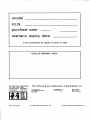


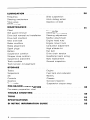

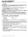


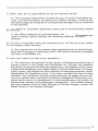


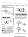
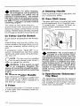
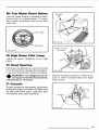
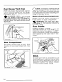
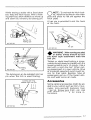

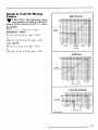
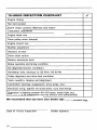
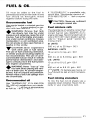
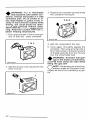

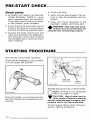


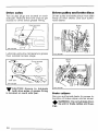
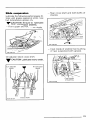

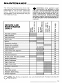

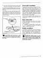
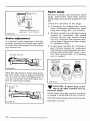

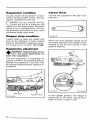
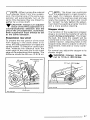
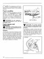
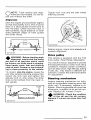

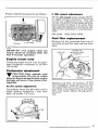
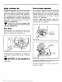
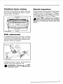
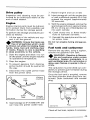
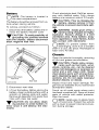
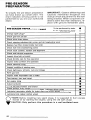
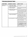
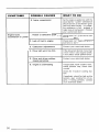
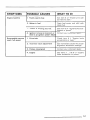


![`95385109 1%]?](http://vs1.manualzilla.com/store/data/005699459_1-7fc02fda0f8970d7c2f678aea00486d8-150x150.png)