1
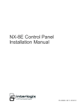
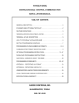
NetworX™ Series
NX-320E REMOTE POWER SUPPLY
Installation and Startup
© 2005 GE Security
All rights reserved.
These instructions do not purport to cover all details or variations in equipment nor to provide every possible
contingency to be met during installation, operation, and maintenance. If further information is desired or if
particular problems arise that are not covered sufficiently for the purchaser’s purpose, the matter should be
referred to GE Security, Gladewater, Texas, USA.
This document contains proprietary information of GE Security, USA and is furnished to its customer solely to
assist that customer in the installation, testing, operations, and/or maintenance of the equipment described.
This document shall not be reproduced in whole or in part nor shall its contents be disclosed to any third party
without the written approval of GE Security.
Please refer to the current GE Security product catalog for detailed warranty information.
Main
800-727-2339
Outside the US
903-845-6941
Main Fax
903-845-6811
Web: www.gesecurity.com
2
Technical Support
Sales & Literature
888-437-3287
800-547-2556
NX-320E Power Supply
TABLE OF CONTENTS
I.
GENERAL DESCRIPTION..................................................................................... 4
II.
ORDERING INFORMATION .................................................................................. 4
III.
UNDERWRITERS LABORATORIES INFORMATION........................................... 4
IV.
ENCLOSURE DIAGRAM ....................................................................................... 5
V.
BATTERY CALCULATION TABLE ....................................................................... 5
VI.
TERMINAL DESCRIPTIONS ................................................................................. 6
VII.
WIRING REQUIREMENTS .................................................................................... 6
VIII. LAYOUT................................................................................................................. 7
IX.
ADDRESSING........................................................................................................ 8
X.
ENROLLING .......................................................................................................... 8
XI.
UNDERSTANDING THE LEDS ............................................................................. 8
XII.
PROGRAMMING ................................................................................................... 9
A.
B.
C.
USING THE LED KEYPAD ............................................................................................................... 9
USING THE LCD KEYPAD ............................................................................................................. 10
PROGRAMMING DATA.................................................................................................................. 10
LOCATION 0
PROGRAMMING EVENT & TIME FOR OUTPUT A ............................ 11
LOCATION 1
PROGRAMMING SPECIAL FEATURES FOR OUTPUT A ................... 12
LOCATION 2
PROGRAMMING THE EVENT & TIME FOR OUTPUT B..................... 12
LOCATION 3
PROGRAMMING SPECIAL FEATURES FOR OUTPUT B ................... 12
LOCATION 4
PROGRAMMING THE EVENT & TIME FOR OUTPUT C .................... 13
LOCATION 5
PROGRAMMING SPECIAL FEATURES FOR OUTPUT C ................... 13
LOCATIONS 6 & 7 RESERVED ......................................................................................... 13
LOCATION 8
CODES 1-10 OUTPUT ENABLE.......................................................... 14
LOCATION 9
CODES 11-20 OUTPUT ENABLE........................................................ 14
LOCATION 10
CODES 21-30 OUTPUT ENABLE........................................................ 14
LOCATION 11
CODES 31-40 OUTPUT ENABLE........................................................ 14
LOCATION 12
CODES 41-50 OUTPUT ENABLE........................................................ 14
LOCATION 13
CODES 51-60 OUTPUT ENABLE........................................................ 14
LOCATION 14
CODES 61-70 OUTPUT ENABLE........................................................ 15
LOCATION 15
CODES 71-80 OUTPUT ENABLE........................................................ 15
LOCATION 16
CODES 81-90 OUTPUT ENABLE........................................................ 15
LOCATION 17
CODES 91-99 OUTPUT ENABLE........................................................ 15
LOCATION 18
A/C DELAY AND DYNAMIC BATTERY TEST ..................................... 15
LOCATION 19
DEVICE OPTIONS............................................................................... 15
XIII. PROGRAMMING WORKSHEETS....................................................................... 16
XIV. SPECIFICATIONS ............................................................................................... 20
NX-320E Power Supply
3
GENERAL DESCRIPTION
I.
The NX-320E is a microprocessor controlled remote power supply module for the NetworX control panels (refer to
Compatibility chart on the back of this manual). This power supply module has three (3) programmable outputs
and one (1) dedicated bell output. A maximum of eight (8) power supply modules can be added to the NetworX
control panel for a total output count of 32, of which 24 are programmable and 8 are dedicated bell outputs. These
24 programmable outputs can be used as auxiliary power, smoke detector power, siren driver power, etc. (see
chart on page 11). Each power supply module has a Tamper terminal that can be used to supervise the metal
enclosure. When the power supply module is connected to the NetworX control panel, the maximum total wire
run from the panel to all devices, including the NX-320E, is 2500 feet. Additionally, the maximum total wire run
from the power supply module to all outgoing devices is 2500 feet.
It is not recommended that multiple power supply modules be connected in series (cascaded).
ORDERING INFORMATION
II.
PART #
DESCRIPTION
PART #
NX-320E
NX-8
Remote Power Supply
NX-8V2 Control Panel only (48 zones)
NX-216E
NX-408E #
NX-8-KIT
NX-8V2 Control, NX-108E LED Keypad, &
16.5V 40VA Transformer
NX-8 Commercial Fire Control Panel in
NX-003-CF Enclosure, (2) NX-148E-CF LCD
keypads; NX-870E Fire Supervision module;
16.5V 50VA Transformer
NX-8E Control Panel only (192 zones)
NX-416E #
NX-8-CF-KIT
NX-8E
NX-448E #
NX-508E
NX-8E-KIT
NX-8E Control, NX-108E LED Keypad, &
NX-870E
16.5V 40VA Transformer
NX-8E-CF-KIT
NX-8E Commercial Fire Control Panel in
NX-003-CF
NX-003-CF Enclosure, (2) NX-148E-CF LCD
keypads; NX-870E Fire Supervision module;
16.5V 50VA Transformer
#
These wireless devices are UL listed for residential applications only.
DESCRIPTION
16 Zone Expander
8 Zone Wireless Expansion Module
(UL LISTED PART #60-904)
16 Zone Wireless Expansion Module
(UL LISTED PART #60-904)
48 Zone Wireless Expansion Module
(UL LISTED PART #60-904)
Eight Output Module
Fire Supervision Module
Commercial Fire Enclosure (Red)
Please refer to the GE Security product catalog for warranty details.
III.
UL365
UL609
UL864
UNDERWRITERS LABORATORIES INFORMATION
Police Station Connected Burglar Alarm Units & Systems
Local Burglar Alarm Units & Systems
Control Units for Fire-Protective Signaling Systems
UL985
UL1023
UL1610
Household Fire Warning Systems
Household Burglar Alarm Systems
Central Station Burglar Alarm Units
When the NX-320E Remote Power Supply is used as part of a UL Commercial Fire security system:
Unit is compatible with the following devices:
o NX-148E-CF LCD keypad
o NX-216E Zone Expander
o NX-507E Relay Expander
o Wheelock NS-1215W or NS-121575W Siren
A minimum of 18AWG shall be used for all field wiring. Shielded wire is not recommended.
Use a 16.5VAC 50VA / 120V, 60Hz hard-wired transformer (Part #T-0002)
4
NX-320E Power Supply
IV.
ENCLOSURE DIAGRAM
Inside the can, several 2-holed insertion points have been constructed. This allows for
either vertical or horizontal placement of the modules. Notice that the insertion points
have two sizes of holes -- a larger hole and a smaller hole.
Diagram 1: The black plastic PCB guides are grooved on one edge where the PC
Board will be seated. The end with the half-moon protrusion fits into the larger hole.
The smaller hole is for the screw.
Diagram 2: Place the first black plastic PCB guide in the top insertion point, grooved
edge downward. The half-moon protrusion will be in the large hole. It does not
require force. Insert one of the provided screws into the smaller hole (from inside the
can) to secure it in place. A screwdriver should reach through the notch that runs the
length of the guide to tighten the screw. The second PCB guide should be positioned
opposite of the first (grooved edge up) and placed in the lower insertion point, using
the same procedures described above. Once mounted, screw it in securely.
Diagram 3: The PC board should slide freely in the grooves of both guides.
V.
BATTERY CALCULATION TABLE
STANDBY TIME
24 hours
48 hours
72 hours
NX-320E Power Supply
TOTAL AUXILIARY
CURRENT
1.9 Amps
1.25 Amps
600 mA
900 mA
600 mA
300 mA
600 mA
400 mA
200 mA
STANDBY BATTERY
CAPACITY
51 AH
34 AH
17 AH
51 AH
34 AH
17 AH
51 AH
34 AH
17 AH
ALARM CURRENT
600 mA
1 Amp
1 Amp
1 Amp
1 Amp
1 Amp
1 Amp
1 Amp
1 Amp
5
VI.
TERMINAL DESCRIPTIONS
Table VI:1
Terminal
Description
DATA
Connect to the Data terminal of the NetworX control panel (refer to Compatibility chart on the
back of this manual). This terminal is the incoming data-signaling terminal to the power supply
module. The maximum total wire run from the control panel to all devices, including the NX320E is 2500 feet.
COM
Connect to the NetworX control panel COMMON terminal. This terminal supplies the
common side of the power to the NX-320E board.
POS
Connect to control panel AUX POWER + terminal. This terminal supplies power to the NX320E board.
DATA
This terminal is the outgoing data-signaling terminal for buss extension. The maximum total
wire run from the NX-320E to all outgoing devices is 2500 feet.
COM
OUT A
Common terminal for any device powered from the NX-320E.
Programmable output current limited to 1.9 Amps.Ê
OUT B
Programmable output current limited to 1.9 Amps. Ê
COM
OUT C
Common terminal for any device powered from the NX-320E.
The total current of the
Programmable output current limited to 1.9 Amps. Ê
NX-320E is 2.5 Amps. ÊÊ
Positive of bell output current limited to 2.5 Amps, but 600mA
for UL applications. Connect as in diagram on page 7.
Negative of bell output current limited to 2.5 Amps, but 600mA
for UL applications. Connect as in diagram on page 7.
BELL +
BELL TAM
EARTH
AC
AC
This is an optional tamper terminal. To use this feature, connect the normally closed tamper
switch between this terminal and COM. If switch 4 is off, this feature is not used.
Earth Ground.
AC Input. Connect to a 16.5V 50 VA Class II UL approved transformer.
AC Input. Connect to a 16.5V 50 VA Class II UL approved transformer.
Ê
Total of 1.9 Amps between outputs A,B,C.
ÊÊ
Total of 2.5 Amps between Bell and outputs.
NOTES: Refer to the control panel compatibility chart on the back of this manual.
Shielded wire is not recommended.
VII.
WIRING REQUIREMENTS
Table VII:1
For UL COMMERCIAL FIRE
installations, a minimum of
18 AWG shall be used for all
field-wiring applications,
regardless of this chart.
6
LENGTH
WIRE GAUGE
(IN FEET)
WHEN CONNECTED TO
NETWORX CONTROL PANEL
400
24
500
24
1000
24
2000
22
2500
20
Note:
Shielded wire is
NOT
recommended.
NX-320E Power Supply
NX-320E Power Supply
UL Installations: The Class 2, Class 3, and powerlimited fire alarm circuits must be installed using
FPL, FPLP, FPLR, CL3, CL3R, or CL3P, or
substitute cable permitted by National Electrical
Code ANSI/NFPA70 and the Class 2, Class 3 and
power-limited fire alarm circuit conductors
extending beyond the cable jacket must be
separated a minimum of ¼ inch or by nonconductive tubing or non-conductive barrier from
all other conductors.
Recommended:
Basler Model BE30614001
120VAC 60Hz
16.5VAC 50VA Class II
LED 3
THE BELL OUTPUT IS VOLTAGE ONLY. IT IS PULSED
(TEMPORAL) DURING A FIRE ALARM AND STEADY
DURING A BURGLAR ALARM. IF THE BELL IS A
COMMERCIAL FIRE BELL, THE DIODE (EOL-D5400) IS
NOT NEEDED.
BATTERY CAPACITY FOR
EMERGENCY STANDBY
AT LEAST 24 HOURS.
CONTROL PANEL DRAWS
50MA STANDBY POWER.
BELL CIRCUIT
CURRENT LIMITED TO
2.5 AMP MAXIMUM
LED 2
CONNECT TO
CONTROL PANEL
DIP
SWITCHES
SHIELDED WIRE IS NOT RECOMMENDED.
LED 1
VIII.
LAYOUT
7
IX.
ADDRESSING
The first thing that must be decided is the address of this particular power supply. This is the address that will be
selected when programming the module. To set the address, use the table below.
Dip Switch 4 is used to disable the Tamper feature (“On = enabled / “Off” = disabled).
Table IX:1
Address
84
85
86
87
88
89
90
91
X.
Dip switch 1
OFF
ON
OFF
ON
OFF
ON
OFF
ON
Dip switch 2
OFF
OFF
ON
ON
OFF
OFF
ON
ON
Dip switch 3
OFF
OFF
OFF
OFF
ON
ON
ON
ON
ENROLLING
The NetworX control panel has the ability to automatically find and store in its memory the presence of all keypads,
zone expanders, wireless receivers and any other module connected to the data terminal. This allows these modules
to be supervised by the control panel. To enroll the modules enter the Program Mode of the NetworX control panel,
and when the Program Mode is exited, it will automatically enroll the devices. The enrolling process takes about 12
seconds, during which time the “Service” LED will illuminate. User codes will not be accepted during the enrolling
process. Once a module is enrolled, if it is not detected by the control, the “Service” LED will illuminate.
XI.
UNDERSTANDING THE LEDS
The power supply module has four (4) red LEDs, which provide valuable information about its status. The following
chart furnishes the indications of each LED.
Table XI:1
8
LED
Description
DS1
Flashes when data is transmitted out from the NX-320E.
DS2
Flashes when data is transmitted into the NX-320E.
DS3
Flashes during normal operation.
DS4
Used for hardware, and will only glow dimly when connected to the NetworX
control panel (refer to Compatibility chart on the back of this manual).
NX-320E Power Supply
XII.
PROGRAMMING
A. USING THE LED KEYPAD
ACTION
RESULT
1. Entering the Program Mode
Enters the Program Mode.
&Á_
Stay, Chime, Exit, Bypass & Cancel LEDS will flash.
& Go To Program Code
Factory
Default
is
`^XZ
If the "Go To Program Code" is valid, the "Service" LED will flash and
the 5 function LEDs will illuminate steady. You are now in the Program
Mode and ready to select the module to program.
2. Entering the Module Address:
&_ ] #
(example only)
Refer to Table IX:1 on page 8 for the module address.
The Armed LED will illuminate while it is waiting for a programming
location to be entered.
3. Programming a Location:
If an attempt is made to program an invalid entry for a particular segment, the keypad
sounder will emit a triple error beep (beep, beep, beep), and remain in that segment
awaiting a valid entry.
To Enter a Location:
&
[location] #
The Armed LED will flash. If the location is valid, the "Armed" LED will
extinguish, the "Ready" LED will illuminate, and the zone LED’s will
show the data for the first segment of this location.
To Change Location Data:
&
[changed data]
& À
The "Ready" LED will flash to indicate a data change in process and
will continue until the data is saved.
The new data is saved.
The keypad will advance to the next segment and display its data.
NOTE: These steps are repeated until the last segment is reached.
NX-320E Power Supply
9
To Exit a Location:
& #
Exits from this location. The “Ready” LED will extinguish. The "Armed"
LED will illuminate waiting for a new programming location to be
entered.
To Review The Data:
&
[location] #
& À
The Armed LED will flash. If the location number is valid, the "Armed"
LED will extinguish, the "Ready" LED will illuminate, and the zone LEDs
will show the binary data for the first segment of this location.
(Do not enter data.)
The next segment is displayed. Each time r is pressed, the data of the
next segment will be displayed for review.
Shortcuts:
&
&
&
Previous location.
Same location.
Next sequential location.
4. Exiting the Program Mode:
& EXIT
Exits this programming level.
B. USING THE LCD KEYPAD
All steps required for programming are the same as the aforementioned LED keypad. The LCD keypad display
will prompt you for the data required. While in the programming mode, and not in a location, the number in
parenthesis is the location you were previously changing. For example, if the display reads, "Enter location, then
# (5)", it is reminding you that location 5 was the last location you programmed. Refer also to "Programming
Data" which follows.
C. PROGRAMMING DATA
Programming data is always one of three types. One type of data is numerical, which can take on values from 0
-15, 0 - F, or 0 - 255 depending on the segment size. The other type of data, feature selection data, is used to
turn features on/off. Use the following procedures with these data types:
1.
Numerical Data
Numerical data is programmed by entering a number from 0-255 on the numeric keys of the system
keypad. To view the data in a location, a binary process is used. With this process, the LED=s for zones 1
through 8 are utilized, and the numeric equivalents of their illuminated LED=s are added together to
determine the data in a programming location. The numeric equivalents of these LED=s are as follows:
Zone 1 LED = 1
Zone 2 LED = 2
10
Zone 3 LED = 4
Zone 4 LED = 8
Zone 5 LED = 16
Zone 6 LED = 32
Zone 7 LED = 64
Zone 8 LED = 128
NX-320E Power Supply
Example: If the numerical data to be programmed in a location is "66", press [6]-[6] on the keypad. The
LED=s for Zone 2 and Zone 7 will become illuminated indicating 66 is in that location (2 + 64 = 66). Once
the data is programmed, press [r] to enter the data and advance to the next segment of that location.
After the last segment of a location is programmed, pressing [r] will exit that location, turn the "Ready" LED
off, and the "Armed" LED on. As before, you are now ready to enter another programming location. If an
attempt is made to program a number too large for a particular segment, the keypad sounder will emit a
triple beep, indicating an error, and remain in that segment awaiting a valid entry.
2. Feature Selection Data
Feature selection data will display the current condition (on or off) of eight features associated with the
programming location and segment selected. Pressing a button on the touchpad (1 thru 8) that
corresponds to the "feature number" within a segment will toggle (on/off) that feature. Pressing any
numeric key between [1] and [8] for selection of a feature will make the corresponding LED illuminate
(feature ON). Press the number again, and the LED will extinguish (feature OFF). You will see that
numerous features can be selected from within one segment. For instance, if all eight features of a
segment are desired, pressing [1]-[2]-[3]-[4]-[5]-[6]-[7]-[8] will turn on LED's 1 thru 8 as you press the keys,
indicating that those features are enabled. LCD Keypad Users Note: The numbers of the enabled features
will be displayed. However, the features not enabled will display a hyphen (-). After the desired setting
of features is selected for this segment, press [r]. This will enter the data and automatically advance to the
next segment of the location. When you are in the last segment of a location and press [r] to enter the
data, you will exit that location. This will now turn the "Ready" LED off and the "Armed" LED on. You are
now ready to enter another programming location.
LOCATION 0
PROGRAMMING EVENT & TIME FOR OUTPUT A
(2 segments of numerical data)
Segment 1 is used to select the particular event that will trigger Output A. See following chart for the specific
events that can be selected.
Segment 2 is used to select the amount of time an output will remain activated when an output triggers. If this
location is programmed as a zero, the output will follow the particular event.
Table XII:1
#
Event
0
Always On
AC Fail (control or exp.) Does not
#
11
Event
Smoke Power Reset
#
22
Event
Disarmed
12
Yelping Siren
23
Ready to Arm
1
follow AC Fail delay time
2
Low Battery (control or exp.)
13
Steady Siren
24
Not Ready to Arm
3
Dynamic Battery Test Time
14
Any Siren
25
Fire
4
Listen In
15
Steady Siren (temporal)
26
Fire Trouble
5
Line Seizure
16
Any Siren (temporal)
27
Chime
6
Telephone Line Fault
17
Alarm Memory
28
Beeping Keypad
7
Program Mode
18
Entry
29
Aux 1 Keypad Function
8
Over-current (control or exp.)
19
Exit
30
Aux 2 Keypad Function
9
Box Tamper (control or exp.)
20
Entry or Exit
31
10
Siren Tamper (control or exp.)
21
Armed
32
Panic Keypad Function
Code Entry (set codes in loc
8 – 17)
If set to follow condition, these events will be one second.
NX-320E Power Supply
11
LOCATION 1
PROGRAMMING SPECIAL FEATURES FOR OUTPUT A
(2 segments of feature selection data)
Segment 1 selects the following special conditions:
1=
2=
3=
4=
5=
6=
7=
8=
"On" if output should time in minutes; "Off" if output times in seconds.
"On" if output should latch until a code is entered; “Off” for timed.
"On" if output should stop time when a code is entered.
“On” for inverted output.
“On” disables output during listen-in (only events 12-16).
Reserved.
Reserved.
Reserved.
Segment 2 selects the following partitions:
1=
2=
3=
4=
5=
6=
7=
8=
"On" if the event should activate when it occurs in Partition 1.
"On" if the event should activate when it occurs in Partition 2.
"On" if the event should activate when it occurs in Partition 3.
"On" if the event should activate when it occurs in Partition 4.
"On" if the event should activate when it occurs in Partition 5.
"On" if the event should activate when it occurs in Partition 6.
"On" if the event should activate when it occurs in Partition 7.
"On" if the event should activate when it occurs in Partition 8.
LOCATION 2
PROGRAMMING THE EVENT & TIME FOR OUTPUT B
(2 segments of numerical data)
Segment 1 is used to program the particular event that will trigger Output B. Refer to Table XII:1 on page 11 for
the specific events that can be selected.
Segment 2 is used to select the amount of time an output will remain activated when an output triggers. If this
location is programmed as a zero, the output will follow the particular event.
LOCATION 3
PROGRAMMING SPECIAL FEATURES FOR OUTPUT B
(2 segments of feature selection data)
Segment 1 selects the following special conditions:
1=
2=
3=
4=
5=
6=
7=
8=
12
"On" if output should time in minutes; "Off" if output times in seconds.
"On" if output should latch until a code is entered; “Off” for timed.
"On" if output should stop time when a code is entered.
"On" for inverted output.
“On” disables output during listen-in (only events 12-16).
Reserved.
Reserved.
Reserved.
NX-320E Power Supply
Segment 2 selects the following partitions:
1=
2=
3=
4=
5=
6=
7=
8=
"On" if the event should activate when it occurs in Partition 1.
"On" if the event should activate when it occurs in Partition 2.
"On" if the event should activate when it occurs in Partition 3.
"On" if the event should activate when it occurs in Partition 4.
"On" if the event should activate when it occurs in Partition 5.
"On" if the event should activate when it occurs in Partition 6.
"On" if the event should activate when it occurs in Partition 7.
"On" if the event should activate when it occurs in Partition 8.
LOCATION 4
PROGRAMMING THE EVENT & TIME FOR OUTPUT C
(2 segments of numerical data)
Segment 1 is used to program the particular event that will trigger Output C. Refer to Table XII:1 on page 11 for
the specific events that can be selected.
Segment 2 is used to select the amount of time an output will remain activated when an output triggers. If this
location is programmed as a zero, the output will follow the particular event.
LOCATION 5
PROGRAMMING SPECIAL FEATURES FOR OUTPUT C
(2 segments of feature selection data)
Segment 1 selects the following special conditions:
1=
2=
3=
4=
5=
6=
7=
8=
"On" if output should time in minutes; "Off" if output times in seconds.
"On" if output should latch until a code is entered; “Off” for timed.
"On" if output should stop time when a code is entered.
"On" for inverted output.
“On” disables output during listen-in (only events 12-16).
Reserved.
Reserved.
Reserved.
Segment 2 selects the following partitions:
1=
2=
3=
4=
5=
6=
7=
8=
"On" if the event should activate when it occurs in Partition 1.
"On" if the event should activate when it occurs in Partition 2.
"On" if the event should activate when it occurs in Partition 3.
"On" if the event should activate when it occurs in Partition 4.
"On" if the event should activate when it occurs in Partition 5.
"On" if the event should activate when it occurs in Partition 6.
"On" if the event should activate when it occurs in Partition 7.
"On" if the event should activate when it occurs in Partition 8.
LOCATIONS 6 & 7 RESERVED
NX-320E Power Supply
13
LOCATION 8
CODES 1-10 OUTPUT ENABLE
(10 segments of feature selection data)
When activating outputs with a user code (event #30), location 8 can be used to restrict certain codes from
activating certain outputs. Location 8 contains 10 segments. Segment 1 corresponds to user 1; Segment 10
corresponds to user 10. The LEDs correspond to outputs A - C.
Table XII:2
LED
LOCATION 9
DESCRIPTION
1
"On" if code will activate Output A; "Off" if it will not.
2
"On" if code will activate Output B; "Off" if it will not.
3
"On" if code will activate Output C; "Off" if it will not.
4
Reserved.
CODES 11-20 OUTPUT ENABLE
(10 segments of feature selection data)
When activating outputs with a user code (event #30), location 9 can be used to restrict certain codes from
activating certain outputs. Location 9 contains 10 segments. Segment 1 corresponds to user 11; Segment 10
corresponds to user 20. The LEDs correspond to outputs A - C (see Table XII:2).
LOCATION 10
CODES 21-30 OUTPUT ENABLE
LOCATION 11
CODES 31-40 OUTPUT ENABLE
LOCATION 12
CODES 41-50 OUTPUT ENABLE
LOCATION 13
CODES 51-60 OUTPUT ENABLE
(10 segments of feature selection data)
When activating outputs with a user code (event #30), location 10 can be used to restrict certain codes from
activating certain outputs. Location 10 contains 10 segments. Segment 1 corresponds to user 21; Segment 10
corresponds to user 30. The LEDs correspond to outputs A - C (see Table XII:2 on page 14).
(10 segments of feature selection data)
When activating outputs with a user code (event #30), location 11 can be used to restrict certain codes from
activating certain outputs. Location 11 contains 10 segments. Segment 1 corresponds to user 31; Segment 10
corresponds to user 40. The LEDs correspond to outputs A - C (see Table XII:2 on page 14).
(10 segments of feature selection data)
When activating outputs with a user code (event #30), location 12 can be used to restrict certain codes from
activating certain outputs. Location 12 contains 10 segments. Segment 1 corresponds to user 41; Segment 10
corresponds to user 50. The LEDs correspond to outputs A - C (see Table XII:2 on page 14).
(10 segments of feature selection data)
When activating outputs with a user code (event #30), location 13 can be used to restrict certain codes from
activating certain outputs. Location 13 contains 10 segments. Segment 1 corresponds to user 51; Segment 10
corresponds to user 60. The LEDs correspond to outputs A - C (see Table XII:2 on page 14).
14
NX-320E Power Supply
LOCATION 14
CODES 61-70 OUTPUT ENABLE
LOCATION 15
CODES 71-80 OUTPUT ENABLE
(10 segments of feature selection data)
When activating outputs with a user code (event #30), location 14 can be used to restrict certain codes from
activating certain outputs. Location 14 contains 10 segments. Segment 1 corresponds to user 61; Segment 10
corresponds to user 70. The LEDs correspond to outputs A - C (see Table XII:2 on page 14).
(10 segments of feature selection data)
When activating outputs with a user code (event #30), location 15 can be used to restrict certain codes from
activating certain outputs. Location 15 contains 10 segments. Segment 1 corresponds to user 71; Segment 10
corresponds to user 80. The LEDs correspond to outputs A – C (see Table XII:2 on page 14).
LOCATION 16
CODES 81-90 OUTPUT ENABLE
LOCATION 17
CODES 91-99 OUTPUT ENABLE
(10 segments of feature selection data)
When activating outputs with a user code (event #30), location 16 can be used to restrict certain codes from
activating certain outputs. Location 16 contains 10 segments. Segment 1 corresponds to user 81; Segment 10
corresponds to user 90. The LEDs correspond to outputs A - C (see Table XII:2 on page 14).
(9 segments of feature selection data)
When activating outputs with a user code (event #30), location 17 can be used to restrict certain codes from
activating certain outputs. Location 17 contains 9 segments. Segment 1 corresponds to user 91; Segment 9
corresponds to user 99. The LEDs correspond to outputs A - C (see Table XII:2 on page 14).
LOCATION 18
A/C DELAY AND DYNAMIC BATTERY TEST
(2 segments of feature selection data)
Location 18 is used to enable the A/C delay and the Dynamic Battery Test, both of which are timed in minutes.
The factory default is 5-0, meaning the A/C power will be off for 5 minutes before a report is sent or a Service light
will illuminate, and the Dynamic Battery Test is disabled (“0” minutes). If you desire the A/C delay to be 8 minutes
and the Dynamic Battery Test to be 3 minutes, you would program [8]-[3].
LOCATION 19
DEVICE OPTIONS
(8 segments of feature selection data)
Location 19 is used to enable various system features of the power supply module.
Table XII:3
LED
1
2
3
4
5-8
Description
On for AC report always sent; Off follows control
If enabled, an AC Fail report will be sent if power is lost for the time programmed in Location 18.
If “off”, the report will only be sent if the control panel has not sent an AC Power Lost report, and
AC Fail report is enabled in Location 37 of the panel.
On enables periodic Battery Test
Enables Battery Missing every 30 seconds.
On enables Low Battery reporting
If enabled, the power supply module will report Low Battery to the central station.
On enables Siren Tamper/Trouble reporting
If enabled, the power supply module will report a Siren Tamper to the central station.
Reserved
NX-320E Power Supply
15
XIII.
PROGRAMMING WORKSHEETS
(Defaults are printed in bold italics text.)
At Default:
LOC
0
1
2
3
4
5
6&7
16
Output A = AUX POWER
Output B = AUX POWER
Output C = SMOKE POWER
PAGE
DESCRIPTION
11
OUTPUT A EVENT & TIME
12
OUTPUT A SPECIAL FEATURES
Segment 1
1 = "On" if timed in minutes; "Off" if timed in
seconds.
2 = "On" if latched until code is entered; “Off” for
timed.
3 = "On" if output should stop time when a code is
entered.
4 = "On" for inverted output.
5 = “On” disables output during listen-in.
6-8 = Reserved
12
OUTPUT B EVENT & TIME
12
OUTPUT B SPECIAL FEATURES
Segment 1
1 = "On" if timed in minutes; "Off" if timed in
seconds.
2 = "On" if latched until code is entered; “Off” for
timed.
3 = "On" if output should stop time when a code is
entered.
4 = "On" for inverted output.
5 = “On” disables output during listen-in.
6-8 = Reserved.
13
OUTPUT C EVENT & TIME
13
OUTPUT C SPECIAL FEATURES
Segment 1
1 = "On" if timed in minutes; "Off" if timed in
seconds.
2 = "On" if latched until code is entered; “Off” for
timed.
3 = "On" if output should stop time when a code is
entered.
4 = "On" for inverted output.
5 = “On disables output during listen-in.
6-8 = Reserved.
13
RESERVED
DEFAULT
0 10
Segment 2
1 = Partition 1
2 = Partition 2
3 = Partition 3
4 = Partition 4
0 10
Segment 2
1 = Partition 1
2 = Partition 2
3 = Partition 3
4 = Partition 4
11 8
Segment 2
1 = Partition 1
2 = Partition 2
3 = Partition 3
4 = Partition 4
DATA
_ _
5 = Partition 5
6 = Partition 6
7 = Partition 7
8 = Partition 8
_ _
5 = Partition 5
6 = Partition 6
7 = Partition 7
8 = Partition 8
_ _
5 = Partition 5
6 = Partition 6
7 = Partition 7
8 = Partition 8
NX-320E Power Supply
LOC
8
PAGE
14
9
14
10
14
11
14
12
14
13
14
14
15
15
15
16
15
17
15
NX-320E Power Supply
DESCRIPTION
Codes 1-10 Output Enable (Circle the numbers to program)
User
1
2
3
4
5
6
1
1
1
1
1
1
Output #A
2
2
2
2
2
2
Output #B
3
3
3
3
3
3
Output #C
Codes 11-20 Output Enable (Circle the numbers to program)
User
11
12
13
14
15
16
1
1
1
1
1
1
Output #A
2
2
2
2
2
2
Output #B
3
3
3
3
3
3
Output #C
Codes 21-30 Output Enable (Circle the numbers to program)
User
21
22
23
24
25
26
1
1
1
1
1
1
Output #A
2
2
2
2
2
2
Output #B
3
3
3
3
3
3
Output #C
Codes 31-40 Output Enable (Circle the numbers to program)
User
31
32
33
34
35
36
1
1
1
1
1
1
Output #A
2
2
2
2
2
2
Output #B
3
3
3
3
3
3
Output #C
Codes 41-50 Output Enable (Circle the numbers to program)
User
41
42
43
44
45
46
1
1
1
1
1
1
Output #A
2
2
2
2
2
2
Output #B
3
3
3
3
3
3
Output #C
Codes 51-60 Output Enable (Circle the numbers to program)
User
51
52
53
54
55
56
1
1
1
1
1
1
Output #A
2
2
2
2
2
2
Output #B
3
3
3
3
3
3
Output #C
Codes 61-70 Output Enable (Circle the numbers to program)
User
61
62
63
64
65
66
Output #A
1
1
1
1
1
1
Output #B
2
2
2
2
2
2
Output #C
3
3
3
3
3
3
Codes 71-80 Output Enable (Circle the numbers to program)
User
71
72
73
74
75
76
Output #A
1
1
1
1
1
1
Output #B
2
2
2
2
2
2
Output #C
3
3
3
3
3
3
Codes 81-90 Output Enable (Circle the numbers to program)
User
81
82
83
84
85
86
Output #A
1
1
1
1
1
1
Output #B
2
2
2
2
2
2
Output #C
3
3
3
3
3
3
Codes 91-99 Output Enable (Circle the numbers to program)
User
91
92
93
94
95
96
Output #A
1
1
1
1
1
1
Output #B
2
2
2
2
2
2
Output #C
3
3
3
3
3
3
7
1
2
3
8
1
2
3
9
1
2
3
10
1
2
3
17
1
2
3
18
1
2
3
19
1
2
3
20
1
2
3
27
1
2
3
28
1
2
3
29
1
2
3
30
1
2
3
37
1
2
3
38
1
2
3
39
1
2
3
40
1
2
3
47
1
2
3
48
1
2
3
49
1
2
3
50
1
2
3
57
1
2
3
58
1
2
3
59
1
2
3
60
1
2
3
67
1
2
3
68
1
2
3
69
1
2
3
70
1
2
3
77
1
2
3
78
1
2
3
79
1
2
3
80
1
2
3
87
1
2
3
88
1
2
3
89
1
2
3
90
1
2
3
97
1
2
3
98
1
2
3
99
1
2
3
17
LOC
18
PAGE
15
19
15
18
DESCRIPTION
A/C Delay (in minutes)
Dynamic Battery Test (in minutes)
Device Options (Circle the numbers to program)
1=On for AC report always sent; Off follows control
2=On enables periodic battery test
3=On enables low battery reporting
4=On enables siren tamper/trouble reporting
DEFAULT
5
0
DATA
___
___
5=Reserved
6=Reserved
7=Reserved
8=Reserved
NX-320E Power Supply
NOTES
NX-320E Power Supply
19
XIV.
SPECIFICATIONS
NX-320E DIMENSIONS
2.0” Wide
9.0” High
4.0” Deep
CURRENT DRAW
AC Input: 120V, 60Hz, 650mA
10 mA Standby
16.5 VAC 50 VA Transformer
AUXILIARY POWER
Limited to 2.5 Amps with 50 VA
12V DC,
BATTERY
51Ah for 24 hrs of battery backup
3 – 17 Ah in parallel
OPERATING TEMPERATURE
32 to 120 degrees F
SHIPPING WEIGHT
8 lbs.
COMPATIBLE CONTROL PANELS:
NX-8 or NX-8V2
NX-8-CF
NX-8E
NX-8E-CF
48 zone Household Fire & Burglary, Commercial Burglary control
48 zone Commercial Fire control
192 zone Household Fire & Burglary, Commercial Burglary control
192 zone Commercial Fire control
Main
800-727-2339
Outside the US
903-845-6941
Web: www.gesecurity.com
NX320EIG05
REV G (June 2005)
Technical Support
Sales & Literature
888-437-3287
800-547-2556