1
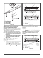
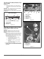
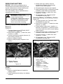
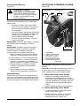
Zoom XL
®
Owner/Operator Manual
Manuel Du Propriétaire/Utilisateur
Models
915163 – Zoom XL 42
(SN 030000 +)
915165 – Zoom XL 48
(SN 030000 +)
915173 – Zoom XL 54
(SN 030000 +)
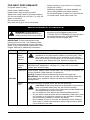
The use of any gasoline exceeding 10% ethanol (E10) or
10% MTBE will void the product warranty.
L’utilisation d’une essence contenant plus de 10%
d’éthanol (E10) ou de 10% de MTBE annulent la garantie.
E10
ENGLISH
FRANÇAIS
ENGLISH
04699800A 9/13
Printed in USA
TABLE OF CONTENTS
Safety . . . . . . . . . . . . . . . . . . . . . . . . . . . 4
Storage . . . . . . . . . . . . . . . . . . . . . . . . . 28
Assembly . . . . . . . . . . . . . . . . . . . . . . . 11
Troubleshooting. . . . . . . . . . . . . . . . . . 29
Controls And Features . . . . . . . . . . . . 13
Service Parts . . . . . . . . . . . . . . . . . . . . 31
Operation . . . . . . . . . . . . . . . . . . . . . . . 14
Accessories . . . . . . . . . . . . . . . . . . . . . 31
Maintenance Schedule . . . . . . . . . . . . 18
Specifications . . . . . . . . . . . . . . . . . . . 32
Service And Adjustments . . . . . . . . . . 20
Warranty . . . . . . . . . . . . . . . . . . . . . . . . 33
INTRODUCTION
THE MANUAL
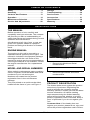
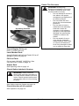
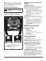
Unit Serial Number Label
Before operation of unit, carefully and
completely read your manuals. The contents
will provide you with an understanding of
safety instructions and controls during normal
operation and maintenance.
All reference to left, right, front, or rear are
given from operator seated in operation
position and facing the direction of forward
travel.
ENGINE MANUAL
The engine on this unit is covered by a
separate manual specific to the engine. This
manual is included in the literature package
that shipped with the unit. Refer to this
manual for engine service recommendations.
If the engine manual is not available, contact
the engine manufacturer for a replacement
manual.
Figure 1
•
Record Unit Model and Serial
numbers here.
•
Record Engine Model and Serial
numbers here.
MODEL AND SERIAL NUMBERS
When ordering replacement parts or making
service inquiries, know the Model and Serial
numbers of your unit and engine.
Numbers are located on the product
registration form in the unit literature
package.
They are printed on a serial number label,
located on the frame of your unit Figure 1.
PRODUCT REGISTRATION
The Ariens dealer must register the product
at the time of purchase. Registering the
product will help the company process
warranty claims or contact you with the latest
service information. All claims meeting
requirements during the limited warranty
period will be honored, whether or not the
product registration card is returned. Keep a
proof of purchase if you do not register your
unit.
Customer Note: If the dealer does not
register your product, please fill out, sign, and
return the product registration card to Ariens.
EN - 2
UNAUTHORIZED REPLACEMENT
PARTS
Use only Ariens replacement parts. The
replacement of any part on this unit with
anything other than an Ariens authorized
replacement part may adversely affect the
performance, durability, and safety of this unit
and may void the warranty. Ariens disclaims
liability for any claims or damages, whether
warranty, property damage, personal injury or
death arising out of the use of unauthorized
replacement parts.
DISCLAIMER
Ariens reserves the right to discontinue,
change, and improve its products at any time
without notice or obligation to the purchaser.
The descriptions and specifications contained
in this manual were in effect at printing.
Equipment described within this manual may
be optional. Some illustrations may not be
applicable to your unit.
DELIVERY
Customer Note: If you have purchased this
product without complete assembly and
instruction by your retailer, it is your
responsibility to:
• Read and understand all assembly
instructions in this manual. If you do
not understand or have difficulty
following the instructions, contact your
nearest Ariens Dealer for assistance.
NOTICE: To locate your nearest Ariens
Dealer, go to www.ariens.com on the Internet.
WARNING: Improper assembly or
adjustments can cause serious
injury.
Before Attempting To Operate Your
Unit:
1. Make sure all assembly has been
properly completed.
2. Understand all Safety Precautions
provided in the manuals.
3. Review control functions and operation
of the unit. Do not operate the unit
unless all controls function as described
in this manual.
4. Review recommended lubrication,
maintenance and adjustments.
5. Review Limited Warranty Policy.
6. Fill out a product registration card and
return the card to the Ariens Company or
go to www.ariens.com.
EN - 3
SAFETY
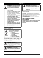
CAUTION: POTENTIALLY
HAZARDOUS SITUATION! If not
avoided, MAY RESULT in minor
or moderate injury. It may also be
used to alert against unsafe
practices.
WARNING: This cutting machine
is capable of amputating hands
and feet and throwing objects.
Failure to observe the safety
instructions in the manuals and
on decals could result in serious
injury or death.
Slopes are a major factor related
to loss-of-control and tip-over
accidents. Operation on all slopes
requires extra caution.
Tragic accidents can occur if the
operator is not alert to the
presence of children. Never
assume that children will remain
where you last saw them.
Gasoline is extremely flammable
and the vapors are explosive,
handle with care.
Disengage attachment, stop unit
and engine, remove key, engage
parking brake, and allow moving
parts to stop before leaving
operator’s position.
NOTATIONS
NOTICE: General reference information for
proper operation and maintenance practices.
IMPORTANT: Specific procedures or
information required to prevent damage to
unit or attachment.
SAFETY DECALS AND
LOCATIONS
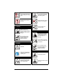
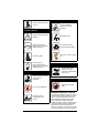
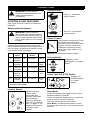
ALWAYS replace missing or damaged Safety
Decals. Refer to Figure 2 for safety decal
locations.
SAFETY ALERTS
Look for these symbols to
point out important safety
precautions. They mean:
• Attention!
• Personal Safety Is
Involved!
• Become Alert!
• Obey The Message!
The safety alert symbol is used in decals and
with this manual. Understand the safety
message. It contains important information
about personal safety.
DANGER: IMMINENTLY
HAZARDOUS SITUATION! If not
avoided, WILL RESULT in death
or serious injury.
WARNING: POTENTIALLY
HAZARDOUS SITUATION! If not
avoided, COULD RESULT in
death or serious injury.
EN - 4
1
07800401
2
5
4
6
KEEP HANDS and FEET AWAY
00
881
029
TO AV
3
P
07800403
Figure 2
1. DANGER!
2. DANGER!
Discharge Hazard –
NEVER operate unit
without discharge chute
in operating position.
Thrown objects can
cause injury or damage.
Discharge Hazard NEVER direct discharge
toward people, pets or
property. Thrown objects
can cause injury or
damage.
Do not operate mower
unless all guards are in
operating position or
bagger is attached.
Dismemberment Hazard –
NEVER stick hands or feet
under deck or shielded
areas.
Shut off engine, remove
key, and read manual
before servicing or making
adjustments to unit.
Keep children and others
away from unit while unit is
in operation.
EN - 5
Keep feet and hands away
from all rotating or moving
parts.
To avoid dismemberment
hazard do not put hands
near moving belts.
DO NOT step or stand in
this area.
Keep hands away from all
rotating or moving parts.
3. DANGER!
Keep all guards and
shields in place.
Discharge Hazard –
NEVER operate unit
without discharge chute in
operating position. Thrown
objects can cause injury or
damage.
4.2 Discharge Hazard
Discharge Hazard –
NEVER direct discharge
toward people, pets or
property. Thrown objects
can cause injury or
damage.
Do not operate mower
unless all guards are in
operating position or
bagger is attached.
Keep children and others
away from unit while unit is
in operation.
4. DANGER!
Do not operate mower
unless all guards are in
operating position or
bagger is attached.
DANGER!
4.3 Tipping Hazard
Read and understand the
operator’s manual before
operating unit.
Avoid tipping hazard.
4.1 Dismemberment Hazard
To avoid dismemberment
hazard do not put hands
near rotating blades.
DO NOT operate on slopes
over 15°.
EN - 6
4.6 Loss of Traction Hazard
DO NOT operate on slopes
over 15°.
If loss of traction is
experienced do the
following:
4.4 Service Hazard
Before servicing unit do the
following:
Disengage PTO.
Read owners manual
before servicing or making
adjustments to unit.
Look before backing.
Proceed off slope slowly.
Set parking brake.
Do not try to turn or speed
up.
P
Remove key and
disconnect spark plug
before servicing or making
adjustments to unit.
5. HOT SURFACES!
DO NOT touch parts
which are hot from
operation. ALWAYS allow
parts to cool.
4.5 Bystander Hazard
DO NOT operate the unit in
the presence of
bystanders.
6. DANGER!
Keep hands and feet
away.
Do not carry passengers.
EMISSION CONTROL SYSTEM
Look behind when
operating the unit in
reverse.
This equipment and/or its engine may include
exhaust and evaporative emissions control
system components required to meet U.S.
Environmental Protection Agency (EPA)
and/or California Air Resources Board
(CARB) regulations. Tampering with emission
controls and components by unauthorized
personnel may result in severe fines or
penalties. Emission controls and components
can only be adjusted by an Ariens Company
EN - 7
dealer or an authorized engine
manufacturer's service center. Contact your
Ariens Company Equipment Retailer
concerning emission controls and component
questions.
SAFETY RULES
If unit is to be used by someone other than
original purchaser; loaned, rented or sold,
ALWAYS provide this manual and any
needed safety training before operation.
Only the user can prevent and is responsible
for accidents or injuries occurring to
themselves, other people or property.
Read, understand, and follow all safety
practices in Owner/Operator Manual before
assembling, using or working on this mower.
ALWAYS remove key from ignition and wire
from spark plug before assembly, or working
on this unit.
Inspect unit before each use for: missing or
damaged decals and shields, correctly
operating safety interlock system, and
deterioration of grass catchers. Replace or
repair as needed.
ALWAYS check overhead and side
clearances carefully before operation.
ALWAYS be aware of traffic when crossing or
operating along streets or curbs.
Keep children, people, and pets away. Be
alert and shut off unit if anyone enters work
area. Keep children under watchful care of a
responsible adult.
NEVER allow children to operate or play on
or near unit.
Keep area of operation clear of all toys, and
debris. Thrown objects can cause injury.
Stay alert for hidden hazards, holes, and ruts.
Avoid uneven or rough terrain. DO NOT
operate near drop-offs, ditches, or
embankments. Unit can suddenly turn over if
a wheel is over the edge of a cliff or ditch, or if
an edge caves in.
Dust, fog, etc. can reduce vision and cause
an accident. Operate unit only when there is
good visibility and light.
Data indicates that operators, age 60 and
above, are involved in a larger percentage of
riding mower related injuries. These
operators should evaluate their ability to
operate the riding mower safely enough to
protect themselves and others from serious
injury.
Wear adequate safety gear, sturdy shoes,
and protective gloves.
Only trained adults may operate unit. Training
includes being familiar with controls and
actual operation.
NEVER operate unit after or during the use of
medication, drugs or alcohol.
NEVER allow anyone to operate this unit
when their alertness or coordination is
impaired.
DO NOT wear loose clothing or jewelry and
tie back hair that may get caught in rotating
parts.
Protect eyes, face and head from objects that
may be thrown from unit. Wear appropriate
hearing protection. Always wear safety
goggles or safety glasses with side shields
when operating mower.
Avoid sharp edges. Sharp edges can cut.
Moving parts can cut off fingers or a hand.
ALWAYS keep hands and feet away from all
rotating parts during operation. Rotating parts
can cut off body parts.
ALWAYS keep hands away from all pinch
points.
Start and operate unit only when seated in
operator’s position. Steering control levers
must be in neutral, PTO disengaged and
parking brake set when starting engine.
ALWAYS keep body and hands away from
pin holes or nozzles which eject hydraulic
fluid under pressure.
DO NOT touch unit parts which might be hot
from operation. Allow parts to cool before
attempting to maintain, adjust or service.
NEVER place your hands or any part of your
body or clothing inside or near any moving
part while unit is running.
NEVER direct discharge towards persons or
property. Thrown objects may ricochet back
towards operator. ALWAYS stand clear of the
discharge area.
ALWAYS disengage attachment, stop unit
and engine, remove key, engage parking
brake, and allow moving parts to stop before
leaving operator’s position.
Use extreme caution on gravel surfaces.
Disengage PTO when attachment is not in
use and when crossing gravel surfaces.
DO NOT operate unit if safety interlock
system is damaged or disabled. Check safety
interlock before each use.
ALWAYS remove key to prevent unauthorized
use.
DO NOT operate at too fast a rate. Slow
down before turning.
EN - 8
Stop engine before removing grass catcher or
unclogging chute.
DO NOT mow on wet grass. Reduced
traction could cause sliding.
DO NOT mow with the deck access plate
open. Always make sure the access plate is
down, or secured down, with the hardware.
DO NOT try to stabilize the machine by
putting your foot on the ground.
Know the weight of loads. Limit loads to those
you can safely control and the unit can safely
handle.
ALWAYS keep protective structures, guards
and panels in good repair, in place and
securely fastened.
Do not operate without either entire grass
catcher or the discharge guard in place.
DO NOT operate in reverse unless absolutely
necessary. ALWAYS look down and behind
before and while backing; especially for
children.
Follow the manufacturer’s recommendations
for wheel weights or counterweights to
improve stability when using attachments.
NEVER carry passengers – especially
children – even with blades off.
Use extra care when approaching blind
corners or objects that may obscure vision of
hidden obstacles and children.
If you cannot back up a slope or you feel
uneasy on it, do not mow it.
Operation on slopes may lead to loss of
steering control. When operating on slopes
be prepared to react to an emergency
situation:
• Return steering levers to neutral
position.
• Immediately set parking brake.
• Turn off PTO and engine.
Mow up and down slopes, not across them.
Use slow speed on any slope. Tires may lose
traction on slopes even though the brakes are
functioning properly.
Keep all movements on the slope slow and
gradual. DO NOT make sudden changes in
speed or direction.
Use extra care while operating machines with
grass catcher or other attachments. They can
affect stability of the machine.
Avoid starting, stopping, or turning on a
slope. If tires lose traction, disengage the
blades and proceed slowly straight down the
slope.
DO NOT operate on slopes over 15°.
DO NOT park on slopes unless necessary. If
unit is parked on a slope, ALWAYS chock or
block wheels and set parking brake.
DO NOT disengage or bypass transmission
and coast downhill.
Tow only with a machine that has a hitch
designed for towing. Do not attach towed
equipment except at the hitch point.
Follow the manufacturer’s recommendations
for weight limits for towed equipment and
towing on slopes.
NEVER allow children or others in or on
towed equipment.
On slopes, the weight of the towed equipment
may cause loss of traction and loss of control.
Travel slowly and allow extra distance to stop.
Use extra care when loading or unloading
unit onto trailer or truck.
Secure unit chassis to transport vehicle.
NEVER secure from rods or linkages that
could be damaged.
DO NOT transport machine while engine is
running.
ALWAYS turn off power to attachment and
shut off fuel when transporting unit.
Keep unit free of grass clippings, leaves, and
other debris. Clean up oil or fuel spills.
This product is equipped with an internal
combustion type engine. DO NOT use unit on
or near any unimproved, forest-covered or
brush covered land unless exhaust system is
equipped with a spark arrester meeting
applicable local, state or federal laws. A spark
arrester, if it is used, must be maintained in
effective working order by operator.
Fuel is highly flammable and its vapors are
explosive. Handle with care. Use only an
approved gasoline container with an
appropriately sized dispensing spout.
NO smoking, NO sparks, NO flames.
ALWAYS allow engine to cool before
servicing.
NEVER fill fuel tank when engine is running
or hot from operation.
NEVER fill or drain fuel tank indoors.
NEVER overfill fuel tank.
Replace fuel cap securely and clean up
spilled fuel.
NEVER fill containers inside a vehicle or on a
truck or trailer bed with a plastic liner. Always
place containers on the ground away from
your vehicle before filling.
EN - 9
When practical, remove gas-powered
equipment from the truck or trailer and refuel
it on the ground. If this is not possible, then
refuel such equipment on a trailer with a
portable container, rather than from a
gasoline dispenser nozzle.
Keep the nozzle in contact with the rim of the
fuel tank or container opening at all times until
fueling is complete. Do not use a nozzle lockopen device.
If fuel is spilled on clothing, change clothing
immediately.
Avoid Electric Shock. Objects contacting both
battery terminals at the same time may result
in injury and unit damage. DO NOT reverse
battery connections.
Explosive Gases from battery can cause
death or serious injury. Poisonous battery
fluid contains sulfuric acid and its contact with
skin, eyes or clothing can cause severe
chemical burns.
NO flames, NO sparks, NO smoking near
battery.
ALWAYS wear safety glasses and protective
gear near battery. Use insulated tools.
Battery posts, terminals and related
accessories contain lead and lead
compounds, chemicals known to the State of
California to cause cancer and reproductive
harm. Wash hands after handling.
ALWAYS keep batteries out of reach of
children.
Reverse connections may result in sparks
which can cause serious injury. Always
connect positive (+) lead of charger to
positive (+) terminal, and negative (-) lead to
negative (-) terminal.
ALWAYS disconnect negative (-) cable FIRST
and positive (+) cable SECOND. ALWAYS
connect positive (+) cable FIRST, and
negative (-) cable SECOND.
A frozen battery can explode and result in
death or serious injury. DO NOT charge or
jump start a battery containing frozen fluid.
Thaw the battery before putting on a charger
or jump starting.
ALWAYS keep protective structures, guards,
and panels in good repair, in place and
securely fastened. NEVER modify or remove
safety devices.
DO NOT change engine governor settings or
over-speed engine.
Fumes from engine exhaust can cause injury
or death. DO NOT run engine in an enclosed
area. Always provide good
ventilation.ALWAYS maintain unit in safe
operating condition. Damaged or worn out
muffler can cause fire or explosion.
Stop and inspect equipment if you strike an
object or if there is an unusual vibration.
Repair, if necessary, before restarting. Never
make adjustments or repairs with the engine
running.
Mower blades are sharp and can cut you.
Wrap the blade(s) or wear gloves, and use
extra caution when servicing them. NEVER
weld or straighten mower blades.
Rotation of one blade may cause rotation of
the other blades.
Check brake operation frequently. Adjust and
service as required.
Keep all hardware properly tightened.
Stored energy in springs can cause injury.
Maintain or replace safety and instruction
labels, as necessary.
Never store the machine or fuel container
inside a building where there is an open
flame, such as a water heater.
Shut off fuel (if provided) and allow engine to
cool completely before storing in closed area
or covering unit.
Clean grass and debris from unit, especially
from around muffler and engine, to help
prevent fires.
For extended storage, clean unit thoroughly.
See Engine Manual for proper storage.
Use only attachments or accessories
designed for your unit.
Check attachment components frequently. If
worn or damaged, replace with
manufacturer’s recommended parts.
EN - 10
ASSEMBLY
WARNING: AVOID INJURY.
Read and understand the entire
Safety section before proceeding.
Tools Required
•
•
•
Adjustable wrench
9/16" wrench
Petroleum jelly or dielectric grease.
1
3
Unpack Unit
Remove unit and all other components from
the shipping container. Engage transmission
bypass lever (see MOVING UNIT
MANUALLY on page 17). Push unit from
container onto a level surface. Disengage
transmission bypass lever.
2
1. Steering Lever
2. Steering Pivot Arm
3. Steering Lever Hardware
Figure 3
Connect Battery
See Battery Removal and Installation on
page 23 and perform steps 4 and 5 in the
installation section.
Place Discharge Chute in Operating
Position
Place Unit in Operating Position
Figure 3
NOTICE: The seat is shipped with the seat
positioned as far back as possible.
1. Push steering levers aside and tip seat
up.
2. Adjust the seat as needed (see
Adjusting Seat on page 16).
3. Remove hardware from top hole of the
steering lever Figure 3. Slide steering
lever back to align slot with hole at the
top of the steering pivot arm.
NOTICE: Do not tighten hardware before
reviewing ADJUSTING STEERING LEVERS
on page 24. If no adjustment is desired
tighten hardware.
4. Adjust steering levers (see ADJUSTING
STEERING LEVERS on page 24).
EN - 11
WARNING: Do not operate
mower unless the discharge chute
is in the operating position.
1. Remove and discard the nuts holding
the discharge chute in transport position.
2. Remove the plastic knobs from the
chute hardware and use to mount the
chute to the deck in operating position.
See Figure 4.
Check Tire Pressure
Transport Position
CAUTION: Avoid injury!
Explosive separation of tire and
rim parts is possible when they
are serviced incorrectly:
• Do not attempt to mount a
tire without the proper
equipment and experience
to perform the job.
• Do not inflate the tires
above the recommended
pressure.
• Do not weld or heat a
wheel and tire assembly.
Heat can cause an
increase in air pressure
resulting in an explosion.
Welding can structurally
weaken or deform the
wheel.
• Do not stand in front or
over the tire assembly
when inflating. Use a clipon chuck and extension
hose long enough to allow
you to stand to one side.
Operating Position
Figure 4
Check Engine Oil Level
See Specifications on page 32.
Refer to Engine Manual.
Level Mower Deck
See LEVELING AND ADJUSTING PITCH OF
MOWER DECK on page 21.
Fill Fuel Tank
Fill fuel tank. DO NOT OVERFILL! See
FILLING FUEL TANK on page 16.
Adjust Seat
See Adjusting Seat on page 16.
Check Safety Interlock System
WARNING: Safety interlock
failure and improper operation of
unit can result in death or serious
injury. Check system before each
use to make sure it is functioning
properly.
See Safety Interlock System on page 14.
Check function of all controls
See Operation on page 14.
EN - 12
CONTROLS AND FEATURES
2
13
5
6
4
11
7
8
1
9
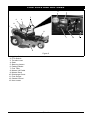
Figure 5
1. Ignition Switch
2. PTO Switch
3. Throttle Lever
4. Seat
5. Steering Levers
6. Parking Brake
7. Fuel Tank
8. Mower Lift Pedal
9. Mower Deck
10. Discharge Chute
11. Fuel Gauge
12. Choke Control
13. Hour meter
EN - 13
12
3
OPERATION
Throttle Lever
WARNING: AVOID INJURY.
Read and understand the entire
Safety section before
proceeding.
1
Fast (1) – Increases
engine speed.
2
Slow (2) – Decreases
engine speed.
CONTROLS AND FEATURES
See Figure 5 for all controls and features
locations.
Safety Interlock System
WARNING: Safety interlock
failure and improper operation of
unit can result in death or serious
injury. Check system before each
use to make sure it is functioning
properly.
Choke Control
Perform the following tests to ensure the
safety interlock system is working properly. If
the unit does not perform as stated contact
your Ariens dealer for repairs.
Test Steering PTO
Lever
1
Parking
Brake
Engine
Engaged
Starts
Neutral
Position
Off
2
Neutral
Position
On
3
Neutral
Position
Off
Disengaged Doesn’t
Start
4*+
Out of
Neutral
Position
Off
Disengaged
Neutral
Position
On
5*+
Use to start a cold engine. Push
the choke lever away from
operator position to start a cold
engine. Pull the choke lever
toward the operator position
when the engine starts to run
smoothly.
NOTICE: Do not choke a warm engine.
Parking Brake
1
Engaged
Engaged
Doesn’t
Start
Shuts
Off
Engages (2) and
disengages (1) parking
brake.
2
Power Take-Off (PTO) Switch
Shuts
Off
1
* Test with engine running.
+ Operator lifts off seat.
Engages (2)
and disengages
(1) mower
blades.
2
Ignition Switch
1
2
3
4
Operate ignition
switch with a
removable key.
Ignition switch has
four positions:
Stop (1), Headlight
(2), Run (3), Start (4).
See on page 17 for
detailed instructions
on how to start
engine.
Hour Meter
Press and release the toggle button to shift
between different functions.
Press and hold the toggle button to reset the
timer or clear a service message.
The hour meter has three functions:
Hour Meter: measures the amount of time
the engine has been run. This time cannot be
cleared.
EN - 14
Timer (TMR1): measures the time spent on
individual jobs.
Press and hold the toggle button to reset the
timer to zero. TMR1 will then start measuring
engine run time until it is reset to zero again.
Service Alert (Chg Oil, Chg H Oil & Filter,
SVC Airfilter): reminds operators of the
maintenance interval for changing the engine
oil, changing the hydraulic oil and filter and
servicing the air filter.
The alert starts counting down two hours
before the maintenance is due. The meter
flashes the word, "Now," when it reaches the
maintenance time.
Press and hold the toggle button to reset the
maintenance clock to zero after performing
the service.
NOTICE: The hour meter is preprogrammed
for the initial oil change at 25 hours and for
100 hours thereafter. The hour meter is
programmed for the initial hydraulic oil and
filter change at 75 hours and for 400 hours
thereafter.
1
2
3
4
NOTICE: To stop, return both steering levers
to neutral.
NOTICE: The steering levers must be in the
neutral position to start the engine.
NOTICE: The parking brake must be
disengaged prior to moving the steering
levers from the neutral position.
Mower Lift Pedal
Figure 6
Raises and lowers the deck.
1
Display
Toggle Button
•
•
•
2
1. Height of Cut Lever
2. Mower Lift Pedal
3. Adjustment Bracket
Steering Levers
•
3
Reverse (1) – Pull both steering levers
backward.
Forward (2) – Push both steering
levers forward.
Left (3) – Pull left steering lever back
or push right steering lever forward or
a combination of both.
Right (4) – Pull right steering lever
back or push left steering lever forward
or a combination of both.
Figure 6
NOTICE: The height of cut lever is used to
set the height of the mower deck. See
Specifications on page 32 for cutting height
dimensions.
Press mower lift pedal and place height of cut
lever to desired adjustment notch.
NOTICE: Adjusting the seat further forward
will help increase the leverage in lifting the
mower deck (see Adjusting Seat on page 16).
EN - 15
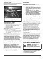
Adjusting Seat
GASOLINE
Lift adjustment lever and slide seat forward or
backward to the desired position.
IMPORTANT: ALWAYS use gasoline that
meets the following guidelines:
• Clean, fresh gasoline.
• A minimum of 87 octane/87 AKI (91
RON). High altitude use may require a
different octane. Consult your engine
manual.
• Gasoline with up to 10% ethanol
(gasohol) or up to 10% MTBE (methyl
tertiary butyl ether) is acceptable.
• Use of any gasoline other than those
approved above will void the engine
warranty. If the pumps are not marked
for the content of alcohol or ethers,
check ethanol and MTBE levels with
the fuel supplier.
• Do not modify the fuel system to use
different fuels.
• Never mix oil and gasoline.
NOTICE: All gasoline is not the same. If the
engine experiences starting or performance
problems after using a new gasoline, switch
to a different fuel provider or fuel brand.
1. Seat
2. Adjustment Lever
1
2
Figure 7
FILLING FUEL TANK
To add fuel to the fuel tank:
1. Clean fuel caps and surrounding area to
prevent dust, dirt, and debris from
entering fuel tanks.
2. Remove fuel caps.
IMPORTANT: Refer to Engine Manual for
correct type and grade of fuel.
3. Fill fuel tank to the bottom of filler neck.
See Specifications on page 32 for fuel
tank capacity.
IMPORTANT: DO NOT OVERFILL! This
equipment and/or its engine may include
evaporative emissions control system
components, required to meet EPA and/or
CARB regulations, that will only function
properly when the fuel tank has been filled to
the recommended level. Overfilling may
cause permanent damage to evaporative
emissions control system components. Filling
to the recommended level ensures a vapor
gap required to allow for fuel expansion. Pay
close attention while filling the fuel tank to
ensure that the recommended fuel level
inside the tank is not exceeded. Use a
portable gasoline container with an
appropriately sized dispensing spout when
filling the tank. Do not use a funnel or other
device that obstructs the view of the tank
filling process.
4. Replace fuel cap and tighten.
5. ALWAYS clean up spilled fuel.
IMPORTANT: Excessively oxygenated or
reformulated fuels (fuels blended with
alcohols or ethers) can damage the fuel
system or cause performance problems. If
any undesirable operating problems occur,
use a gasoline with a lower percentage of
alcohol or ether.
Fuel Stabilizer
Gasoline left in the fuel system for extended
periods without a stabilizer will deteriorate,
resulting in gum deposits in the system.
These deposits can damage the carburetor
and the fuel hoses, filter and tank. Prevent
deposits from forming in the fuel system
during storage by adding a quality fuel
stabilizer to the fuel. Follow the
recommended mix ratio found on the fuel
stabilizer container.
STOPPING IN AN EMERGENCY
WARNING: Operating unit on
slopes may lead to loss of
steering control. When operating
on slopes be prepared to react to
an emergency situation.
1. Return steering levers to neutral position.
2. Immediately set parking brake.
3. Turn off PTO and engine.
EN - 16
STARTING AND SHUTTING OFF
ENGINE
NOTICE: This unit is not equipped with the
return to neutral function. The control arms
must be manually brought back to neutral
from the forward position.
Starting the Engine
MOVING UNIT MANUALLY
WARNING: DO NOT disengage
or bypass transmission and coast
downhill.
Disengage (2) transmission bypass levers to
drive unit and engage (1) transmission
bypass levers to push unit manually Figure 8.
NOTICE: Disengage the PTO, engage the
parking brake, and place the steering levers
in neutral prior to starting the engine.
1. If the engine is cold, push the choke
control away from operator position to
start. If the engine is warm or hot, do not
use choke.
2. Move the throttle to 1/3 Fast position.
See Engine Manual for detailed
instructions.
IMPORTANT: DO NOT operate starter for
more than 15 seconds per minute as damage
can occur.
3. Turn ignition key to start position and
release once the engine has started.
4. Pull the choke lever toward operator
position when the engine is warm. Wait
until the engine is running smoothly
before operation.
IMPORTANT: Let the engine warm up
several seconds to several minutes
depending on outside temperature.
Stopping the Engine
1. Stop unit.
2. Disengage PTO.
3. Set throttle lever to slow.
4. Turn ignition switch to off position and
remove key.
5. Set parking brake.
OPERATING MOWER
1. Start engine.
2. Set throttle lever to fast.
1
2
1. Transmission Bypass Lever Engaged
2. Transmission Bypass Lever
Disengaged
Figure 8
IMPORTANT: Never engage PTO if mower is
plugged with grass or other material.
3. Engage PTO to start mower blades.
NOTICE: The parking brake must be
disengaged prior to moving the steering
levers from the neutral lockout position.
4. Release parking brake.
5. Use steering levers to move the unit.
6. Disengage PTO to stop mower blades.
TRANSPORTING UNIT
ALWAYS shut off engine, set parking brake,
remove key, and close fuel shut-off valve or
drain fuel when transporting unit on a truck or
trailer. Tie unit down securely. Do not tie
down by linkages, guards, cables or other
parts that may be damaged.
EN - 17
FOR BEST PERFORMANCE
Cut grass when it is dry.
Keep mower blades sharp.
Keep mower deck properly leveled.
Adjust anti-scalp rollers to prevent scalping.
Do not set height of cut too low. For very tall
grass, mow twice.
Do not travel too fast.
Mow with the engine set at full throttle.
When mulching, only remove 1/3 of grass
length per cutting.
Discharge clippings into areas already cut.
Vary cutting pattern with each mowing.
Do not allow grass or debris to collect inside
of mower deck. Clean after each use.
MAINTENANCE SCHEDULE
WARNING: AVOID INJURY.
Read and understand the entire
Safety section before proceeding.
NOTICE: To have full access to the engine,
the seat must be tipped forward (see
TIPPING SEAT FORWARD on page 20) and
the hood opened (see OPENING AND
CLOSING HOOD on page 20).
IMPORTANT: Proper maintenance can
prolong the life of unit. The following chart
shows the recommended service schedule.
Refer to the maintenance instructions in the
Engine Manual for additional information.
Interval
Task
Action
Check
Safety
Interlock
System
Check
Parking
Brake
WARNING: Safety interlock system failure and improper
operation of unit can result in death or serious injury. Test
this system each time the unit is operated. If this system
does not function as described, do not operate until repairs
are made (see Safety Interlock System on page 14).
Engage parking brake and engage transmission bypass lever (see
MOVING UNIT MANUALLY on page 17). Push unit. If unit rolls,
contact your Ariens Dealer.
Clean Unit Clean engine, battery, seat, mower deck, etc. of all dirt and debris. Do
not use solvents, hard cleaners, or abrasives.
NOTICE: Protect painted surfaces with automotive type wax.
IMPORTANT: Do not spray the unit with water, especially when the
unit is warm from operation. Water can seep into bearings and
Each Use
damage them.
Check
Tires
See Specifications on page 32 for correct tire pressure.
•
•
•
CAUTION: Avoid injury! Explosive separation of tire and rim
parts is possible when they are serviced incorrectly:
•Do not attempt to mount a tire without the proper equipment
and experience to perform the job.
Do not inflate the tires above the recommended pressure.
Do not weld or heat a wheel and tire assembly. Heat can cause
an increase in air pressure resulting in an explosion. Welding
can structurally weaken or deform the wheel.
Do not stand in front or over the tire assembly when inflating.
Use a clip-on chuck and extension hose long enough to allow
you to stand to one side.
EN - 18
Interval
Task
Check
Mower
Blades
Follow
Engine
Manual
Each Use Maintenance
Schedule
Action
CAUTION: Check for worn or damaged mower blades.
Perform scheduled engine
maintenance. Refer to Engine
Manual for detailed instructions.
NOTICE: To drain the oil, use the oil
drain hose (1) supplied with unit, not
the drain plug that is shown in the
Engine Manual.
1
Check
Battery
Keep battery and battery terminals clean (see Cleaning Battery and
Battery Cables on page 23).
Lubricate
Unit
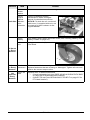
Apply grease to zerk (1) on each
front wheel
25 Hours
or Every
Season
1
50 Hours Check
or Every Fasteners
Season
Check mower blade mounting hardware and all other fasteners.
Replace fasteners that are missing or damaged. Tighten all nuts and
bolts to the correct torque value.
Check All
100
Belts
Hours or
Every
Season
Replace worn or deteriorated belts.
• Check hydrostatic belt (see REPLACING HYDROSTATIC BELT
on page 26 for hydrostatic belt location).
• Check PTO belt (see REPLACING PTO BELT on page 25 for
PTO belt location).
EN - 19
SERVICE AND ADJUSTMENTS
WARNING: AVOID INJURY.
Read and understand the entire
Safety section before proceeding.
OPENING DECK ACCESS PLATE
1. Put parking brake on.
2. Adjust height of cut lever to 4.5 in.
(11.4 cm) position Figure 11.
3. Raise deck access plate.
TIPPING SEAT FORWARD
Move steering levers to neutral position and
rotate handles outward. Tip seat forward.
Seat Tipped Forward
2
1
1. Height of Cut Lever
2. Deck Access Plate
Figure 11
Figure 9
REPLACING MOWER BLADE
Remove
OPENING AND CLOSING HOOD
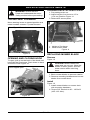
To open, pull up on the back of the hood until
hood hits the hood stops. Push down on back
of hood to close Figure 10.
Figure 12
CAUTION: Mower blades are
sharp and can cut you. Wrap the
blades or wear gloves, and use
extra caution when servicing
them.
Hood tipped open.
1. Block mower blades to prevent rotation.
2. Remove mounting hardware and mower
blades from mower deck.
Install
Figure 12
1. Install mower blades on mower deck
with mounting hardware.
2. Torque 5/8" hex bolt to 80 – 120 lbf-ft
(108 –163 N•m).
Figure 10
EN - 20
3
Lowest Cutting Position
1
2
1-1/2" + 1/4" (3.8 cm + 0.64 cm)
1
Highest Cutting Position
1
3
2
2
4
3
4-1/2" + 1/4" (11.4 cm + 0.64 cm)
1.
2.
3.
4.
Flat Washer
Bevel Washer
5/8" Hex Bolt
Mower Blade
1. Mower Deck
2. Mower Blade
3. Ground
Figure 12
Figure 13
LEVELING AND ADJUSTING
PITCH OF MOWER DECK
The Forward Pitch Of The Mower
Blades
NOTICE: Adjust on a level surface, with the
tires inflated to the correct air pressure (see
Specifications on page 32).
There are three measurements required to
level and adjust the pitch of the mower deck.
1. The distance from the mower blades to
the ground.
2. The forward pitch of the mower blades.
3. The pitch of the mower blades from
side-to-side.
Figure 14
• Should be 0" – 1/4" (6.35 mm) pitched
forward.
NOTICE: This measurement must be taken
when the mower blades ends are facing
forward.
Forward Pitch of Mower Blades
2
1
3
The Distance From The Mower
Blades To The Ground
Figure 13
• In the lowest cutting position should be
1-1/2" + 1/4" (3.8 cm + 0.64 cm).
• In the highest cutting position should
be 4-1/2" + 1/4" (11.4 cm + 0.64 cm).
Forward Pitch = 0" – 1/4"
(6.35 mm)
1. Mower Deck
2. Mower Blade
3. Ground
Figure 14
EN - 21
Front of
Mower
Deck
The Pitch Of The Mower Blades From
Side-To-Side
Figure 15
• Should be within 1/4" (6.35 mm) as
measured on each side of the mower
deck.
NOTICE: This measurement must be taken
when the mower blade ends are
perpendicular (at a right angle) to the frame
of the unit.
1
Side-To-Side Pitch
3
1
3
2
1.
2.
3.
4.
5.
6.
2
5
4
Rear Trunnion
PTO Belt
Mower Deck
Drag Link
Front Trunnion
Lift Arm
Figure 16
1/4" (6.35 mm) from Side-To-Side
1. Mower Deck
2. Mower Blade
3. Ground
Figure 15
1
Adjusting The Mower Deck To Adjust
Mower Blade Height And Pitch
Figure 17
NOTICE: Adjusting the mower deck will
adjust the height and pitch of the mower
blades.
1. Adjust the trunnions first and re-take the
three measurements required to level
and adjust the pitch of the mower deck.
These measurements are:
a. The distance from the mower
blades to the ground.
b. The forward pitch of the mower
blades.
c. The pitch of the mower blades
from side-to-side.
2. Repeat step 1 as needed until all three
measurements are within the tolerances
specified.
2
3
1. Deck Link
2. Mower Deck
3. Trunnion
Figure 17
EN - 22
6
SERVICING BATTERY
3. Rotate and align battery bracket
lengthwise to battery, ensuring tab
corner is flush with battery.
4. Reinstall taptite fastener and tighten.
5. Apply petroleum jelly or dielectric grease
to battery cable ends and terminals.
6. Connect positive (+) cable first, then
negative (–) cable.
7. Tip seat back (see TIPPING SEAT
FORWARD on page 20).
NOTICE: Unit comes equipped with a
maintenance-free battery that requires no
regular maintenance except cleaning the
terminals and periodic charging.
This style battery can be replaced with a
standard size U1 battery.
WARNING: Battery posts,
terminals and related accessories
contain lead and lead
compounds, chemicals known to
the State of California to cause
cancer and reproductive harm.
Wash hands after handling.
Cleaning Battery and Battery Cables
Battery Removal and Installation
Remove
Figure 18
1. Tip seat forward (see TIPPING SEAT
FORWARD on page 20).
2. Disconnect negative (–) cable first, then
positive (+) cable.
3. Loosen and remove taptite fastener (2)
from battery bracket (1).
4. Remove battery bracket.
5. Remove and properly dispose of old
battery.
2
Figure 19
1. Tip seat forward (see TIPPING SEAT
FORWARD on page 20).
2. Disconnect negative (–) cable first, then
positive (+) cable.
3. Clean battery cable ends, negative (–)
terminal, and positive (+) terminal with a
wire brush and rinse with a weak baking
soda solution.
4. Apply petroleum jelly or dielectric grease
to battery cable ends and terminals.
5. Connect positive (+) cable first, then
negative (–) cable.
6. Tip seat back (see TIPPING SEAT
FORWARD on page 20).
4
1
1.
2.
3.
4.
5.
6.
7.
1. Battery Bracket
2. Taptite Fastener
Figure 18
Install
6
7
3
2
1
Battery Bracket
Taptite Fastener
Negative (–) Cable
Negative (–) Terminal
Battery
Positive (+) Cable
Positive (+) Terminal
Figure 19
Figure 19
1. Remove taptite fastener located by
battery decal.
2. Install replacement battery into battery
channel.
EN - 23
5
Charging the Battery
ADJUSTING STEERING LEVERS
Figure 19
Figure 20
WARNING: FROZEN
BATTERIES CAN EXPLODE
and result in death or serious
injury. DO NOT charge a frozen
battery. Let the battery thaw
before charging.
Adjustment 3
3
1
Follow First Aid directions for contact with
battery fluid.
• External Contact: Flush with water.
• Eyes: Flush with water for at least 15
minutes and get medical attention
immediately!
• Internal Contact: Drink large quantities
of water. Follow with Milk of Magnesia,
beaten egg or vegetable oil. Get
medical attention immediately!
• In case of internal contact, DO NOT
induce vomiting!
Adjustment 1
2
IMPORTANT: DO NOT fast charge. Charging
at a higher rate will damage or destroy
battery.
IMPORTANT: ALWAYS follow information
provided on battery and battery charger.
Contact battery and battery charger
manufacturers for detailed instructions.
1. Remove battery from unit (see Battery
Removal and Installation on page 23).
2. Place battery in a well-ventilated area.
3. Connect positive (+) lead of charger to
positive (+) terminal, and negative (–)
lead of charger to negative (–) terminal.
4. Charge battery according to battery
charger and battery manufacturers’
instructions.
5. Install battery on unit (see Battery
Removal and Installation on page 23).
Jump-Starting
Ariens does not recommend jump-starting
your unit. Jump-starting can damage engine
and electrical system components. See your
engine manual for more detailed information.
6
5
4
Adjustment 2
1.
2.
3.
4.
5.
6.
Handlebar
Upper Control Arm
Adjustment Holes
Eccentric Spacer
Mounting Hardware
Lower Control Arm
Figure 20
IMPORTANT: Adjust each steering lever
equally.
NOTICE: When adjusting steering levers for
the first time it is recommended that you
make adjustments in the following order.
1. Adjust Steering Lever Height
1. Remove mounting hardware that
attaches the handlebars to the upper
control arm. Move handlebar up or down
until the handlebar mounting holes are
aligned with the prefered adjustment
holes.
2. Install mounting hardware and tighten.
2. Adjust Steering Lever Width
1. Loosen hardware at the base of the
lower control arm item 5.
2. Rotate eccentric spacer to move the
levers away from or closer to the
operators position (figure 21).
EN - 24
2. Adjust speed by loosening jam nut and:
• Turning adjustment bolt clockwise to
decrease steering lever travel.
• Turning adjustment bolt counter
clockwise to increase steering lever
travel.
Eccentric Spacer
Rotate this end away from the operator
position to move the steering levers in.
Rotate this end away from the operator
position to move the steering levers out.
Figure 21
3. Adjust Steering Lever Forward or
Backward
1. Loosen, do not remove, the bolts
securing the handlebar to the upper
control arm.
2. Slide steering lever forward or backward
to desired position and tighten bolts.
NOTICE: Tighten upper bolt first.
2
3
1
1. Forward Travel Adjustment Bolt
2. Rear Travel Adjustment Bolt
3. Lower Control Arm
Figure 22
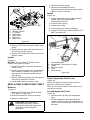
REPLACING PTO BELT
Remove
Forward and Reverse Speed
Adjustment
Figure 22
IMPORTANT: The unit should track within
2’ (0.610 m) of a straight line for 30’ (9.14m).
The travel of the steering levers may need
adjustment if:
• The unit turns to the right or left when
both steering levers are pushed as far
forward as possible.
• The unit turns to the right or left when
both steering levers are pulled back as
far rearward as possible.
NOTICE: The side the unit turns toward
indicates that the wheel on that side is turning
slower than the other wheel. Either the wheel
that is turning faster needs to slow down or
the wheel that is turning slower needs to be
sped up to allow the unit to travel in a straight
line.
1. Determine which way the unit turns.
NOTICE: The forward travel adjustment bolt
adjusts the rear travel of the steering lever.
The rear travel adjustment bolt adjusts the
forward travel of the steering lever.
Figure 23
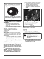
1. Lower mower deck to the ground.
2. Remove belt covers from mower deck.
EN - 25
CAUTION: Use care when
releasing idler spring tension.
Keep body parts well away from
idler when performing this
operation.
3. Hook a puller into idler hole and pull idler
arm towards outside of unit until tension
is removed from PTO belt.
3
4
4. Disconnect idler spring.
5. Remove hydrostatic belt from
hydrostatic transmission pulleys, pulley,
electric clutch, and idler.
5
6
Install
2
Figure 24
1. Install hydrostatic belt on idler, electric
clutch, pulley, and hydrostatic
transmission pulleys.
2. Connect idler spring.
3. Install clutch stop.
4. Connect electric clutch connector.
5. Install PTO belt (see REPLACING PTO
BELT on page 25).
1
7
1.
2.
3.
4.
5.
6.
7.
Idler Spring
Electric Clutch
PTO Belt
Idler Hole
Idler Pulley
Idler Arm
Belt Cover
1
6
2
Figure 23
4. Remove PTO belt from left mower deck
pulley.
5. Slowly release idler arm until tension is
removed from idler spring.
6. Remove PTO belt from mower deck and
electric clutch.
2
3
4
5
Install
Figure 23
NOTICE: Do not install PTO belt on left
mower deck pulley in step 1.
1. Install PTO belt on electric clutch and
mower deck.
2. Hook a puller into idler hole and pull idler
arm towards outside of unit until PTO
belt can be routed around left mower
deck pulley.
3. Slowly release idler arm until idler pulley
rests firmly against PTO belt.
4. Install belt covers on mower deck.
REPLACING HYDROSTATIC BELT
Remove
Figure 24
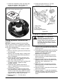
1. Remove PTO belt (see REPLACING
PTO BELT on page 25).
2. Disconnect electric clutch connector.
3. Remove clutch stop.
CAUTION: Use care when
releasing idler spring tension.
Keep body parts well away from
idler when performing this
operation.
1.
2.
3.
4.
5.
6.
Hydrostatic Belt
Hydrostatic Transmission Pulley
Pulley
Electric Clutch
Idler
Idler Spring
Figure 24
Check Hydraulic Fluid Level
Figure 25
Check the system with the unit cold and
parked on a flat, level surface.
Then run the unit for about one minute and
recheck the levels.
To Add Hydraulic Fluid:
Figure 25
1. Remove the cap from the expansion
tank.
2. Fill the expansion tank with 20W-50
engine oil with an SL API classification
until oil level reaches the cold fill line on
the tank.
EN - 26
3. Install the expansion tank cap and then
purge the system. See “Purging the
Hydraulic System” on page 27.
9. Follow the instructions in “To Add
Hydraulic Fluid:” on page 26.
1
2
The hydraulic fluid should be at the cold
fill line of the expansion tank.
3
4
1. Drain Plug
2. Oil Filter
3. Filter Guard
4. Mounting Hardware
Figure 26
Purging the Hydraulic System
Figure 25
Change Hydraulic Fluid and Filter
Figure 26
NOTICE: Change hydraulic fluid and filter
after the first 75 hours of operation and then
every 400 hours. Use 20W-50 engine oil with
an SL API classification.
1. Place container under oil filter to catch
oil.
2. Remove the filter guard and oil filter from
the transaxle.
3. Remove the oil drain plug or fitting from
the inlet port and allow the transaxle to
drain completely.
4. Clean the filter mounting surface and
then lubricate rubber gasket on new oil
filter with clean hydraulic oil.
5. Spin new oil filter onto filter housing until
it makes contact. Tighten oil filter
another 3/4 turn.
6. Install the filter guards removed in
step 2. Tighten the mounting screws to
5.38 lbf-ft (7.3 N•m).
7. Fill with 20W-50 engine oil with an SL
API classification until oil appears at the
bottom of the drain plug (about 2 quarts
per transaxle). Install the drain plug and
tighten it to 14.97 lbf-ft (20.3 N•m).
8. Repeat steps 1 – 7 for the other
transaxle.
EN - 27
WARNING: This adjustment
requires operating the engine.
Use extreme care to avoid
contact with moving parts and hot
surfaces. Be sure rear of unit is
well supported and secure before
starting engine.
1. With the unit up to and facing a wall, jack
up the unit so that both drive wheels are
off the ground.
2. Disengage the parking brake and put the
transaxle bypass levers in the neutral
position (see MOVING UNIT
MANUALLY on page 17).
3. Start the engine and slowly move the
steering levers in forward and reverse
five or six times.
4. Stop the engine and put the transaxle
bypass levers in the drive position (see
MOVING UNIT MANUALLY on
page 17).
5. Start the engine and slowly move the
steering levers in forward and reverse
five or six times.
6. Stop the engine, check the oil level and
add oil as needed.
7. Repeat steps 2 – 6 until the transaxles
operate smoothly in forward and reverse
at normal speeds without excessive
noise.
STORAGE
Short Term Storage
Add Fuel Stabilizer
IMPORTANT: NEVER clean unit with highpressure water or store unit outdoors.
Remove all dirt, grease, leaves, etc. Store in
a clean dry area.
Inspect unit for signs of wear or damage.
Ensure all fasteners are properly tightened.
Long Term Storage
Follow all instructions under Short Term
Storage.
Remove and fully charge battery. Store in a
clean dry area.
Refer to Engine Manual for the proper engine
storage procedures.
Touch up all scratched or chipped paint
surfaces.
Fuel System
Gasoline left in the fuel system for extended
periods without a stabilizer will deteriorate,
resulting in gum deposits in the system.
These deposits can damage the carburetor
and the fuel hoses, filter and tank. Prevent
deposits from forming in the fuel system
during storage by adding a quality fuel
stabilizer to the fuel. Follow the
recommended mix ratio found on the fuel
stabilizer container.
IMPORTANT: NEVER store the engine with
fuel in the fuel tank inside of a building with
potential sources of ignition.
EN - 28
1. Turn the fuel valve off while engine is
running and allow the engine to run until
it stops. Turn engine OFF when it begins
surging to avoid engine damage.
2. Add fuel stabilizer, following the
manufacturer’s instructions.
3. Turn fuel valve on after adding fuel
stabilizer.
4. Re-start engine.
5. Run the engine outdoors for 1 minute to
be sure that treated gasoline has
replaced the untreated gasoline in the
carburetor.
6. Slow the engine to an idle speed.
7. Stop engine.
TROUBLESHOOTING
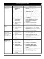
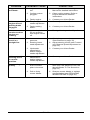
PROBLEM
Engine will not
crank/start.
Engine runs
rough.
Unit does not
move with
engine running
when using
steering levers.
PTO or mower
blades do not
engage or shuts
off.
PROBABLE CAUSE
CORRECTION
1. Safety interlock
system is not
engaged or is
faulty.
1. Check safety interlock system (see
Safety Interlock System on
page 14).
2. Fuel tanks empty.
2. Fill fuel tanks (see FILLING FUEL
TANK on page 16).
3. Discharged
battery.
3. Charge battery (see Charging the
Battery on page 24).
4. Poor connection
between battery
and battery cables.
4. Tighten battery cables and/or clean
battery and battery cables (see
Cleaning Battery and Battery Cables
on page 23).
5. Spark plug wire(s)
loose or spark
plug(s) faulty.
5. Connect spark plug wire(s) or
replace spark plug(s). Refer to
Engine Manual for detailed
instructions.
6. Faulty electrical
system.
6. Contact your Ariens Dealer.
7. Faulty engine.
7. Contact your Ariens Dealer.
1. Choke engaged.
1. Disengage choke.
2. Air filter cartridge
plugged.
2. Clean or replace air filter cartridge.
Refer to Engine Manual for detailed
instructions.
3. Faulty engine.
3. Contact your Ariens Dealer.
1. The transmission
bypass lever is
engaged.
1. Disengage transmission bypass
lever (see on page 18).
2. Faulty hydrostatic
belt.
2. Replace hydrostatic belt (see
REPLACING HYDROSTATIC BELT
on page 26).
3. Faulty
transmission.
3. Contact your Ariens Dealer.
1. Operator presence
switch not
depressed.
1. Depress operator presence switch
by sitting on seat.
2. Faulty operator
presence switch.
2. Contact your AriensDealer.
3. Electric clutch
connector is loose
or disconnected.
3. Connect the electric clutch
connector. See REPLACING
HYDROSTATIC BELT on page 26
for the electric clutch connector
location.
4. Faulty PTO belt.
4. Replace PTO belt (see REPLACING
PTO BELT on page 25).
5. Faulty PTO switch,
wires, connectors,
or clutch.
5. Contact your Ariens Dealer.
EN - 29
PROBLEM
Engine
overheats.
PROBABLE CAUSE
CORRECTION
1. Engine oil level
low.
1. Add engine oil. Refer to Engine
Manual for detailed instructions.
2. Cooling system
plugged.
2. Clean cooling system. Refer to
Engine Manual for detailed
instructions.
3. Faulty engine.
3. Contact your Ariens Dealer.
Unit moves with
engine off and
parking brake
engaged.
1. The parking brake
needs adjustment.
1. Contact your Ariens Dealer.
2. Faulty parking
brake.
2. Contact your Ariens Dealer.
Hour meter
continues when
engine not
running.
1. Ignition key is in
the run position
with engine turned
off.
1. Turn ignition key to the off position.
Unit does not
travel in a
straight line.
1. Incorrect tire
pressure.
1. Check tire pressure (see
Specifications on page 32)
2. Steering levers
need adjustment.
2. Adjust steering levers (see Forward
and Reverse Speed Adjustment on
page 25)
3. Hydrostatic
transmission
and/or linkage
needs adjustment.
3. Contact your Ariens Dealer.
Unit creeps with
steering levers
in neutral
position.
1. Hydrostatic
transmission
and/or linkage
needs adjustment.
1. Contact your Ariens Dealer.
Poor cutting
quality.
1. Mower deck not
level or mower
pitch is incorrect.
1. Level and adjust pitch of mower
deck (see The Distance From The
Mower Blades To The Ground on
page 21).
2. Dull or faulty
mower blades.
2. Sharpen mower blades or replace
mower blades (see REPLACING
MOWER BLADE on page 20).
EN - 30
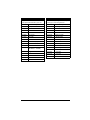
ACCESSORIES
See your authorized Ariens dealer to add
these optional accessories to your unit.
Part No.
SERVICE PARTS
Be sure to always use genuine Ariens parts
to keep your unit running like new.
Description
Part No.
Description
71502900
Dump Cart
21541700
Spark Plug
71509000
42" Mulch Kit
21541500
Fuel Filter
71508700
48" Mulch Kit
21550700
Air Filter
71509100
54" Mulch Kit
21550800
Engine Oil Filter
71503200
48" Aerator
21545100
Hydraulic Oil Filter
71503300
36" Roller
02961600
42" Mower Blade
71503400
48" Dethatcher
03288600
42" Mulching Blade
71510300
15 – Gallon Sprayer
02982000
48" Mower Blade
71503600
Spreader
00273000
48" Mulching Blade
71509200
Sunshade
02961700
54" Mower Blade
81502200
3 – Bag Powered Bagger
(SN 000101 – 029999)
03288700
54" Mulching Blade
07242200
Hydrostatic Belt
07200037
42" PTO Belt
07200436
48" PTO Belt
07200023
54" PTO Belt
81515400
Bagger Kit
71509300
Trailer Hitch
51526000
Deck Kit CE
71509400
Light Kit
71513300
XL – 42" Blow Out Baffle Kit
EN - 31
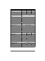
SPECIFICATIONS
Model Number
915163
915165
915173
Model
Zoom XL 42
Zoom XL 48
Zoom XL 54
Engine
Kohler
Kohler
Kohler
44.2 (725)
Displacement – in. 3 (cc)
Max Governed RPM
(May be different from maximum RPM)
3600 ± 0
- 100
Speed
Forward Max. – m.p.h. (km/h)
6.5 (10.46)
Reverse Max. – m.p.h. (km/h)
3 (3.2)
Turning Radius
Zero
Brakes
Internal Transmission
Electrical
Starter
Electric
Battery
12 Volt Maintenance Free
PTO (Power Take Off)
Electric Clutch/Brake
Fuel
Fuel Type
Refer to Engine Manual
Fuel Tank Capacity – gal. (L)
4.5 (17.0)
Transmission
Hydrostatic Drive
Size and Weight
Length – in. (cm)
69 (175.3)
Width – in. (cm)
52 (132.1)
58 (124.5)
56 (147.3)
Weight – lbs. (kg)
615 (279.5)
630 (286.4)
645 (293.2)
Height – in. (cm)
42 (106.7)
Tires
Front Tire Size – in.
Rear Tire Size – in.
11 x 4
20 x 8
20 x 10
Front Tire Pressure – psi (kPa)
46 (317)
Rear Tire Pressure – psi (kPa)
10 (69)
Mower Deck
Cutting Height – in. (cm)
Cutting Width – in. (cm)
1.5 – 4.5 (3.81 – 11.4)
42 (107)
48 (122)
Max. Towing Capacity – lbs. (kg)
300 (136)
Max. Tongue Weight – lbs. (kg)
30 (13.6)
EN - 32
54 (137)
Consumer Mowing Equipment
Limited Warranty
Ariens Company (Ariens) warrants to the original purchaser that Ariens, Gravely and Countax brand lawn
and garden consumer products purchased on or after 1/1/2012 will be free from defects in material and
workmanship for the time period noted in the chart below. Equipment put to personal use around a single
household or residence is considered “Consumer Use”; equipment put to any business use (agricultural,
commercial, or industrial) or used at multiple locations is considered “Commercial Use.” If any product is
rented or leased, then the duration of these warranties shall be 90 days after the date of purchase.
An authorized Ariens dealer (Ariens brand products), Gravely dealer (Gravely brand products), or Countax
dealer (Countax brand products) will repair any defect in material or workmanship, and repair or replace any
defective part, subject to the conditions, limitations and exclusions set forth herein. Such repair or
replacement will be free of charge (labor and parts) to the original purchaser except as noted below.
Warranty
Code
Product Group
Warranty Period
Consumer Use
Warranty Period
Commercial Use
HA
Zoom & ZT Zero-Turn Riders;
AMP™ Rider
3 Years
90 Days
HB
Max Zoom & ZT HD Zero-Turn Riders
3 Years
1 Year
HC
Tractors, "961" Series Walk-Behind
Mowers
2 Years
90 Days
HD
Classic LM Series Mowers; Wide Area
Walk Mowers
3 Years
90 Days
N/A
Service (replacement) Parts
90 Days (no labor)
90 Days (no labor)
Special Extensions
The chart below details special extensions to this warranty:
Warranty
Code
Warranty Exception
Warranty
Period
Use
Detail
HA, HB
Mower Deck Shell on
Zero-Turn Riders
5 Years
Consumer
3 years parts and labor
Additional 2 years parts only
HA, HB
Main Frame on
Zero-Turn Riders
5 Years
Consumer
3 years parts and labor
Additional 2 years parts only
Batteries for AMP™ Rider
2 Years
Consumer
100% first year; prorated second year
HA
Exceptions and Limitations
The chart below details special exceptions to this warranty:
Warranty
Code
Warranty Exception
Warranty
Period
All
Batteries
1 Year
All
Belts, Muffler, Tires
None
All
Cloth, Plastic, and
Rubber Components
(Including Belts and
Cables)
All
Engines
Use
Detail
Consumer Prorated
components are not covered
Commercial These
when used commercially.
Maximum
2 Years
All
Warranty is limited to 2 years for
consumer use. Except as noted above,
these components are covered for
defect, not for wear.
See Engine
Manufacturer’s
Warranty
All
Engines are covered by engine
manufacturer’s warranty. Refer to
engine manufacturer’s warranty
statement.
Customer Responsibilities
Register the product immediately at the time of sale. If the dealer does not register the product, the
customer must complete the product registration card in the literature package and return it to the Ariens
Company, or register the unit online at www.ariens.com, www.gravely.com, www.countax.com.
EN - 33
Consumer 2012 Rev. A
To obtain warranty service, the original purchaser must:
• Perform the maintenance and adjustments explained in the owner's manual.
• Promptly notify Ariens or an authorized Ariens, Gravely or Countax service representative of the need for
warranty service.
• Transport the product to and from the place of warranty service at owner's expense.
• Have the warranty service performed by an authorized Ariens, Gravely or Countax service representative.
To Find an Authorized Service Representative:
In the U.S. and Canada:
Use the dealer locator on our websites:
www.ariens.com
•
www.gravely.com
Or contact us by mail or by phone:
In the U.S., Canada, Mexico, Caribbean, In Europe, Asia, Africa or
Central and South America:
the Middle East:
Ariens Company
655 W. Ryan Street
Brillion, WI 54110
Phone: (920) 756 - 4688
www.ariens.com
Countax Ltd, Countax House
Great Haseley, Oxfordshire,
OX44 7PF
Phone: 0800 597 7777
www.countax.com
In Australia or New Zealand:
Ariens Company
Building 2
6 Wedgewood Rd.
Hallam, Victoria 3803 Australia
Phone: (03) 9796 4244
1800 335 489
www.ariens.com.au
Exclusions – Items Not Covered by This Warranty
• Parts that are not genuine Ariens, Gravely or Countax service parts are not covered by this warranty and
may void the warranty.
• Damages resulting from the installation or use of any part, accessory, or attachment which is not approved
by the Ariens Company for use with product(s) identified herein are not covered by this warranty.
• The following maintenance, service and replacement items are not covered by this warranty unless they
are noted in the Limitations section above: lubricants, spark plugs, oil, oil filters, air filters, fuel filters,
brake linings, brake arms, brake shoes, skid shoes, scraper blades, shear bolts, mower blades, mower
vanes, brushes, headlights, light bulbs, knives, cutters.
• Any misuse, alteration, improper assembly, improper adjustment, neglect, or accident which requires
repair is not covered by this warranty.
• Use of gasoline blends exceeding 10% ethanol voids any and all warranties.
• Products are designed to the specifications in the area that the product was originally distributed. Different areas may have significantly different legal and design requirements. This warranty is limited to the
requirements in the area in which the unit was originally distributed. Ariens Company does not warrant
this product to the requirements of any other area. Warranty service is limited to service within the area
originally distributed.
• In countries other than the United States and Canada, contact the Ariens Company dealer for warranty
policies that govern within your country. Rights may vary from country to country and within any one
country.
Disclaimer
Ariens Company may from time to time change the design of its products. Nothing contained in this warranty
shall be construed as obligating the Ariens Company to incorporate such design changes into previously
manufactured products, nor shall such changes be construed as an admission that previous designs were
defective.
LIMITATION OF REMEDY AND DAMAGES
Ariens Company's liability under this warranty, and under any implied warranty that may exist, is limited to
repair of any defect in workmanship, and repair or replacement of any defective part. Ariens Company shall
not be liable for incidental, special, or consequential damages (including lost profits). Some states do not
allow the exclusion of incidental or consequential damages, so the above limitation or exclusion may not
apply to you.
AUSTRALIAN CONSUMER LAW
The following applies solely to warranties subject to Subsection 102(1) of the Australian Consumer Law: Our
goods come with guarantees that cannot be excluded by the Australian Consumer Law. You are entitled to a
replacement or refund for a major failure and for compensation for any other reasonably foreseeable loss or
damage. You are also entitled to have the goods repaired or replaced if the goods fail to be of acceptable
quality and failure does not amount to a major failure.
DISCLAIMER OF FURTHER WARRANTY
Ariens Company makes no warranty, express or implied, other than what is expressly made in this
warranty. If the law of your state provides that an implied warranty of merchantability, or an implied
warranty of fitness for particular purpose, or any other implied warranty, applies to Ariens Company,
then any such implied warranty is limited to the duration of this warranty. Some states do not allow
limitations on how long an implied warranty lasts, so the above limitation may not apply to you.
This warranty gives you specific legal rights, and you may also have other rights which vary from region to region.
EN - 34
Consumer 2012 Rev. A
Ariens
655 West Ryan Street
Brillion, WI 54110
920-756-4688
Fax 920-756-2407
www.ariens.com
WARNING
The engine exhaust from this product
contains chemicals known to the State
of California to cause cancer, birth
defects or other reproductive harm.