1
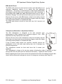
Bell System (Telephones) Ltd. bellfree Digital Video Door Entry System With Hands-free Colour Apartment Stations Installation & Operation Manual This manual applies to the following: BFD-DIG Digital Door controller – Version 1 Builds 1 BF Colour Apartment Station – Version 1 Build 1 to 2 BS Colour Videophone – Version 2 Builds 1 to 3 BSA Audio Phone – Version 1 Build 1 BSC4 Video Controller – Version 2 Build 7 PD–166 Issue 1 21 September 2010 BF Apartment Station Digital Entry System bellfree Apartment Station BFD-DIG controller BSC4 controller BSA audiophone BS videophone BS Deskphone PD–166 Issue 1 Installation and Operating Manual Page 2 of 48 BF Apartment Station Digital Entry System TABLE OF CONTENTS TABLE OF CONTENTS ...................................................................................................... 3 INTRODUCTION ................................................................................................................. 4 DESCRIPTION ..................................................................................................................... 4 MAIN FEATURES ................................................................................................................. 4 BASIC SYSTEM OPERATION ............................................................................................ 6 DESIGN CONSIDERATIONS .............................................................................................. 9 EQUIPMENT LIST................................................................................................................. 9 OPTIONS ............................................................................................................................ 9 POWER SUPPLY REQUIREMENTS ....................................................................................... 10 CABLE SPECIFICATION ...................................................................................................... 12 CABLE DISTANCES ............................................................................................................ 13 INSTALLATION & COMMISSIONING .............................................................................. 14 CHECKLIST ....................................................................................................................... 14 WIRING ............................................................................................................................ 14 COMMISSIONING ............................................................................................................... 18 BFD-DIG DOOR CONTROLLER SETTINGS .......................................................................... 19 BFD-DIG DOOR CONTROLLER JUMPER SETTINGS .............................................................. 22 BSC4 VIDEO CONTROLLER SETTINGS................................................................................ 23 BF APARTMENT STATION SWITCH SETTINGS ...................................................................... 25 BS VIDEOPHONE SWITCH SETTINGS .................................................................................. 26 TROUBLESHOOTING ...................................................................................................... 27 COMMON FAULTS ............................................................................................................. 27 QUICK FAULT REFERENCE................................................................................................. 27 SPECIFICATIONS ............................................................................................................. 30 DIAGRAM A – BASIC SYSTEM WIRING OVERVIEW ..................................................... 33 DIAGRAM B – BFD_DIG PCB DETAIL ............................................................................ 34 DIAGRAM C – BFD-DIG KEYPAD MATRIX ..................................................................... 34 DIAGRAM D – BASIC SYSTEM WIRING DETAIL ........................................................... 35 DIAGRAM E – BSC4 PCB DETAIL .................................................................................. 36 DIAGRAM F – BSC4 WIRING DETAIL ............................................................................. 37 DIAGRAM G – LARGE SYSTEM OVERVIEW ................................................................. 38 DIAGRAM H – EXTENSION APARTMENT STATION WIRING ....................................... 39 DIAGRAM I – APARTMENT STATION LOCAL POWER WIRING .................................. 40 DIAGRAM J – CAMERA SHARING & TIME CLOCK SHARING ..................................... 41 DIAGRAM K – COMBINED CONNECTIONS BELLFREE WITH LOCK .......................... 42 DIAGRAM L – COMBINED CONNECTIONS THIRD PARTY LOCK................................ 44 SAFETY INFORMATION AND DECLARATIONS ............................................................ 47 PD–166 Issue 1 Installation and Operating Manual Page 3 of 48 BF Apartment Station Digital Entry System Introduction Description A bellfree video door entry system consists of a door panel, positioned at the entrance of a building, apartment stations and other telephones, placed inside of the building for the convenience of the occupants and a power supply and controller which are usually located inside an electrical cupboard. The door panel comprises of a two-way speech unit, a camera, an LED display and sixteen push buttons – which are used by a visitor to initiate a call. The apartment station, which rings in response, allows a two-way hands free conversation (a touch is required to initiate the conversation and end the conversation) whilst the caller can be observed through the integral display. The operator can selectively allow visitors access to the building by touching a pad on the apartment station and so electrically releasing the door. The bellfree digital video door entry system is suitable for any building or entry point addressing a quantity of flats where a standard panel would be larger or more expensive; this is typically from 16 flats upwards. The bellfree digital system is supplied with a dedicated door controller, for each entrance, and a video controller for every four apartment stations. The basic system supports 1 apartment station per address, and up to 3 extension apartment stations (more with additional power supplies). Multiple entrances can be supported with the addition of one panel and one door controller for each entrance. Main Features ● Enhanced audio for hands free operation ● Cat5 cable throughout; no co-ax required! ● 3.5” Flat screen high resolution TFT colour display. ● High resolution CCD colour day/night camera with infrared lamps. ● 12V d.c. operation ● High quality full-duplex speech amplifier. ● Automatic picture display while ringing. ● Ringer mute function. ● Ringer volume control. ● Fail safe or fail secure lock releases and magnetic locks (maglock). ● Lock release timer. ● Tradesman facility (optional). ● Facility for exit button and/or fire switch. ● Door open indication. ● Second camera option. ● Up to 3 extension apartment stations per flat. ● Mixed systems with BS videophones and BSA audio phones ● Multiple entrances supported. PD–166 Issue 1 Installation and Operating Manual Page 4 of 48 BF Apartment Station Digital Entry System bellfree Colour Apartment Station View Pickup Display Contrast Mute Lock Ringer Volume System Symbol Mute on/off Pickup / end View / camera select Lock PD–166 Issue 1 Lamp Red Steady Flashing Apartment station is muted Doorbell – All Flash Blue Call in progress Green Door is open Installation and Operating Manual Ringing Touch to release lock Page 5 of 48 BF Apartment Station Digital Entry System Basic System Operation Panel Controls Call Button Cancel Button Reception or Porter Button Door Button (Trades) Number and Letter Buttons The numbers 0 to 9 are used to enter numbers. The letter button >A enters letters beginning with A and each press advances through the alphabet, while the letter button <Z does the reverse starting with Z. For example pressing >A three times will give C then pressing <Z once will give B, or starting with Z; pressing 5 times will give V and then pressing >A twice will give X. The call button is used to call flats or acts as a bell button calling the reception phone. The cancel button cancels the current entry leaving a blank display. The reception (AKA Porter or Concierge) button calls a pre-defined phone dedicated to that location. The door or Trades button is used to gain direct access either directly or via a code. Call sequence When the resident‟s address is entered followed by the call button the addressed apartment station will ring and its blue pickup / view lamp will flash, highlighting the pickup and view symbols. The apartment station will continue to ring for up to 30 seconds or until the resident responds by touching the view symbol (see silent viewing below) or the pickup symbol. After using the pickup symbol the resident can freely converse with the visitor whose image is now displayed on the apartment station; at the same time the green lock symbol will flash to highlight the lock function. PD–166 Issue 1 Installation and Operating Manual Page 6 of 48 BF Apartment Station Digital Entry System The call may be terminated by touching the pickup symbol again or more usually by touching the lock symbol first to allow the visitor access through the entrance; the speech and picture will persist for a further 3 seconds while the door is being released. Silent viewing When the apartment station is ringing the resident can touch the view symbol to answer the call instead of the pickup symbol; this will stop the apartment station ringing and enable them to view the visitor for up to 60 seconds or until the lock symbol is touched to release the door. Silent viewing can be „normalised‟ at any time by touching the pickup symbol and conversing with the visitor as described above. Apartment Station Controls The diagram in the introduction shows the apartment station and its controls. The controls are adjusted by touching the end of the slider and sliding the finger up and down. The default setting is ringer volume halfway and contrast slider fully down. Auto Display When „Auto Display‟ mode is selected the picture will come on while the apartment station is ringing, otherwise the picture will only come on when the call is answered. Auto Display mode is usually pre-selected at installation and generally only one apartment station per flat should be set in this mode (see „Extension Apartment Stations‟ below). Ringer Mute The resident can mute the ringing sound in the apartment station when they do not wish to be disturbed. Ringer mute is activated by touching the mute symbol on the apartment station, which then illuminates in red as a reminder. Touching the mute symbol a second time will disengage the mute function. Ringer Mute only stops the audible ring, but the blue ring lamp will still flash and all other functions work normally. Ringer mute will continue for the pre-set time even if a call is answered. During installation it is possible to set a time limit for the mute function in various values from 2 minutes up to 10 hours or indefinitely. When this time period has elapsed the mute function will automatically disengage. Default timeout is never (See „mute timer‟, page 25). Door Status Indication The green lock lamp on the apartment station will illuminate to warn the resident that a door has been left open following a call. This feature requires a door monitor contact to be fitted. Call Privacy Once a call has been made from an entrance panel only the apartment station(s) which is / are ringing may answer the call. Once the call is answered another apartment station will not activate (including extensions of the active apartment station). User Activation (CCTV Mode) User activation is a feature of the bellfree 1 way system and is not available on digital systems. User activation is generally not recommended on larger systems as the conflicting demands of residents and callers can result in confusion and erroneous fault reports. PD–166 Issue 1 Installation and Operating Manual Page 7 of 48 BF Apartment Station Digital Entry System Cameras The door controller has the capability of using one or two cameras, for instance a second panel camera for DDA or a „third party‟ „CCTV‟ camera located to offer a different entrance viewpoint. Touching the view symbol will alternate the view between camera 1 and camera 2 (if enabled). Note. The camera to controller wiring has termination options which allow for connections to other video equipment. See the Camera sharing diagram on page 41 for details. Extension Apartment Stations Additional apartment stations may be added to each „flat‟. The number of extensions is limited only by power supply considerations. All apartment stations for that „flat‟ will ring when called however typically only the master unit will display a picture while ringing. Once the master or extension apartment station is „picked-up‟ the picture will display on that unit alone. Lock Type The door controller supports both fail-secure and fail-safe locks including magnetic locks of up to 1A rating. The lock time may be programmed between 1 and 99 seconds. (See „Lock Release Operating time‟ and „Lock Type‟ on page 20. Exit Button and Fire Switch An input is provided for an exit button, which can be installed on the inside of the door and allow residents to exit freely. Momentary operation of this button will operate the lock release for the programmed lock time. A Fire switch or other override device may use the same input to hold the door open indefinitely. Note. Fail secure locks must be continuously rated. Trades Facility The trades facility is accessed by pressing the door button. An optional time clock may be used to allow one function during the programmed time(s) and another at all other times. These functions can be: – unlock the door, ask for an entry code or ignore the button press. There are 2 entry codes available, a residents code and a tradesman‟s code. DDA Functionality The bellfree digital video system has a range of options for entrance panels to help meet the requirements of the Disability Discrimination Act (DDA), including Illuminated Tactile buttons and reassurance tones to indicate apartment station ringing and door released. Contact your sales representative for further details. Multiple Entrances The bellfree system allows multiple entrances to be catered for by the addition of a door controller and entrance panel for each entrance and additional power supplies. Gate and Block Systems Sites with two or more blocks sharing one or more site entrances are catered for with our BSSW Gate controller. The blocks can then work independently but will receive calls from the shared entrance. For further details see the “bellissimo and Bellcall Manual Gate and Block (PD-120)”. PD–166 Issue 1 Installation and Operating Manual Page 8 of 48 BF Apartment Station Digital Entry System Design Considerations Equipment List A bellfree digital video system comprises the following: Model No N x BF 1 x BFP-DIG/LCP -OR1 x BFP-DIG/VR(S) 1 x BFD-DIG M x BSC4 K x PS4 1 x 203 Description Colour Apartment station (N is the no of phones) Laser Cut panel with a BF-AMP speech unit, camera, VR buttons and LED display. Flush fitting only. Vandal resistant panel with a BF-AMP speech unit, camera, VR buttons and LED display. Flush or surface mounting. Door controller Video controller (one required for every 4 ways = N/4 rounded up) 4A 12V power supply. (one required for every 8 to 16 ways) Fail-secure lock release, alternate types available. Options The following options are available: ● Extensions model BF apartment station(s). ● Extensions using Video Phones model BS. ● Extensions using Audio only phones model BSA. ● Additional entrances, each comprising a BFD-DIG controller and BFP-DIG panel. (See also power supply requirements). ● Alternative lock releases, fail-safe and fail-secure. ● Timed Trades facility; specify a model TS2000-BST time-clock. ● Exit button. Model 5077 surface and model 5078 flush versions are available. ● Battery back-up power supply, Model 840 (12V 4A). ● DDA panels (Contact sales for further information). Entrance Panel – Important Note Careful consideration should be given to the location of the entrance panel to ensure the best possible lighting conditions for the camera. In general strong back lighting of the subject (by the sun and sky) should be avoided, as the contrast between foreground and background may be too great for the camera. The field of view should contain as little of the sky as possible, particularly if south facing. If a backlit situation is unavoidable, additional lighting may be necessary to illuminate the caller and avoid a dark outline image (silhouette). A light coloured or reflective surface around the panel will redirect backlight to illuminate the caller. Door Controller The door controller and power supply should be wall-mounted in a convenient cupboard or other protected environment with available mains power. Cable length to the entrance should be less than 50m. The door controller for the second and subsequent entrances may be situated in the same location, or to meet the 50m requirement may be situated in another location. Power supplies may be shared between door controllers placed in the same location, but controllers in separate locations must be separately powered. PD–166 Issue 1 Installation and Operating Manual Page 9 of 48 BF Apartment Station Digital Entry System Video Controller The video controller(s) and power supply(ies) should be wall-mounted in a convenient cupboard or other protected environment with available mains power. Cable length to the apartment station should be less than 150m, see „Cable Distances‟ page 13. In many cases the video controllers will be in the same location as the door controller(s), but they may be distributed as required to reduce wiring distances. When placed in different locations, each location must have its own local power supplies. Gate Controller The gate switch controller BSSW is wired between the block door controllers and the video controllers, so would normally be wall mounted next to a door controller. For further details see the “bellissimo and Bellcall Manual Gate and Block (PD-120)”. Separately Powered Apartment Stations The limitation of up to 4 apartment stations ringing but only one displaying, as indicated in the power supply and cable distance tables on page 13, can be overcome by the use of supplementary power from a 340C. Power Supply Requirements The system is powered by 12V power supplies only: Model PS4 12V, 4A. Model 840 12V, 4A battery backup supply. Model 340C 12V, 1.5A optional for extensions. Note 1. The 28V referred to on the apartment station, video controller and wiring diagrams is internally generated in the controller. DO NOT use any power supply other than 12V or damage may occur. Note 2. The PS4 power supply has been specifically designed to operate with the highsurge requirements of the system. Bell System is unable to guarantee functionality or provide support for systems which use third party power supplies. PD–166 Issue 1 Installation and Operating Manual Page 10 of 48 BF Apartment Station Digital Entry System Exact power supply requirements depend upon many factors. The number of power supplies included within a standard „kit‟ or quotation assumes that all controllers are installed in one location and that there are no extensions. The following table gives examples of the minimum number of controllers and power supplies for a given number of entrance doors and flats. System Control Equipment and Power Supplies 1 door 16 flats 1 x BFD-DIG door controller for digital panel 4 x BSC4 video controller 2 x PS4 12V 4A power supply 1 door 20 flats 1 x BFD-DIG door controller for digital panel 5 x BSC4 video controller 2 x PS4 12V 4A power supply 1 door 36 flats 1 x BFD-DIG door controller for digital panel 9 x BSC4 video controller 3 x PS4 12V 4A power supply 2 door 36 flats 2 x BFD-DIG door controller for digital panel 9 x BSC4 video controller 4 x PS4 12V 4A power supply Distributed installations will typically require more power supplies. Also the use of other equipment such as coded access or proximity readers must be taken into account. The following table is a guide to how much equipment a PS4 power supply can safely and reliably feed, please contact technical support for other variations. Equipment 1 x PS4 can power 4 x BSC4 video controllers with 1 BF apartment station per output. 1 x BSC4 video controllers with 2 to 4 BF apartment stations per output. 1 to 3 BSC4‟s phones + extensions 1 x BFD-DIG door controller and 2 x BSC4 video controllers with 1 BF apartment station per output 1 x BFD-DIG door controller and 1 x BSC4 video controllers with 2 to 4 BF apartment stations per output 2 x BFD* door controllers (any type) with up to 2 cameras and 1A fail safe locks. PD–166 Issue 1 Comments 16 apartment stations directly powered. Extensions may be added if separately powered by 340C‟s. Extension phones must be set to ring only, use the above configuration to allow the extensions to have a picture while ringing. 16 apartment stations directly powered 8 apartment stations directly powered. Extensions may be added if separately powered by 340C‟s. Extension phones must be set to ring only, use the above configuration to allow the extensions to have a picture while ringing. Both door controllers must be in the same location. No spare current available for other equipment unless both cameras or all the lock current is not used. Installation and Operating Manual Page 11 of 48 BF Apartment Station Digital Entry System Cable Specification All system wiring must be carried out using Cat5 signal cable and where necessary 1mm² (or greater) power cable as tabulated below. Cat5 cable has a known performance for the transmission of video signals, whilst telephone or alarm cables are not suitable. Bell System will be unable to offer any warranty or support for systems installed using incorrect cables. Cat5 Cable Specification Cat5 is our short reference for EIA standard UTP Category 5 Unshielded Twisted Pair data cable. This is a standard solid core twisted pair cable having 4 pairs (8-cores) and no shield. The cores are in pairs where Blue and „Blue with a White stripe‟ are twisted together as the first pair. The other three pairs are similar with main colours Orange, Green and Brown. Also available and acceptable are: UTP Category 5e (Cat5e) UTP Category 6 (CAT6) UTP Category 6e (CAT6e) The exact cable can be chosen from the above on cost and availability grounds. STP (Shielded Twisted Pair) cables are not recommended. UTP “patch cables” are not recommended. NOTE: Cat5 cable is easily identifiable as the specification is printed on the sheath PD–166 Issue 1 Installation and Operating Manual Page 12 of 48 BF Apartment Station Digital Entry System Cable Distances Video Controller to BF Apartment Station System Distance Cable Comments Single apartment station < 150m 1 x Cat5 per output or first < 300m 1 x Cat5 apartment station 2 x 1mm2 Single apartment station < 50m 1 x Cat5 Only Master apartment station + 3 extensions on each has „Auto display‟; < 200m 1 x Cat5 2 output, all cable powered extensions are daisy-chained 2 x 1mm Single apartment station < 150m 1 x Cat5 150m maximum to the cable per output with separately < 300m powered apartment station; 1 x Cat5 powered extensions daisy-chain up to 300m total. 2 x 1mm2 All apartment stations < 300m 1 x Cat5 Locally powered apartment locally powered with a stations have „Auto display‟; <25m to 340C 1 x pair of 340C power supply extensions are daisy-chained Cat5 2 <100m to 340C 2 x 1mm System All Systems Distance <200m Door Controller to Video Controller(s) Cable Comments 1 x Cat5 N.B. maximum length from any camera to any apartment station must be less than 300m Panel to BDF-DIG Door Controller System Distance Cable Comments All Systems, each entrance <50m 1 x Cat5 Speech and video only BFP-DIG/LCP <50m 7 x pair of Cat5 Doubled up power BFP-DIG/VR(S) <50m 7 x pair of Cat5 Doubled up power Lock Release up to 1A <10m 1 x pair of Cat5 <50m 2 x 1mm2 Option: Exit button <50m 1 x pair of Cat5 Option: Door Monitor Switch <50m 1 x pair of Cat5 Power Supply to Controller System Distance Cable Comments All Systems, each PS4 to BFD- <3m 2 x 1mm2 Total length of any daisy chain 2 DIG or BSC4 <5m 2 x 1.5mm NB. A Cat5 cable has 4-pairs (8 cores) For larger cable distances please contact manufacturer. PD–166 Issue 1 Installation and Operating Manual Page 13 of 48 BF Apartment Station Digital Entry System Installation & Commissioning Checklist The following checklist is a summary of what is required. Refer to the relevant pages for further details. ● Review the section headed „Safety Information‟ on page 47. ● Ensure that „Design Considerations‟ on page 9 have been understood. ● Confirm that Cat5 cable has been specified. ● Install the system according to instructions in this section. ● Check/set the door controller settings. ● Check/set the video controller jumper and switch settings. ● Check/set each apartment station dip-switch settings. Wiring Refer to the diagrams from page 33 onwards as appropriate for the equipment you have. All wiring is carried out using a mixture of Cat5 for the signal wiring and 1mm² (or greater) cores for the power wiring; refer to Page 12 for further details. It is strongly recommended that a consistent colour code be used throughout such as that indicated on the connection diagram. Certain signals must be interconnected using a twisted pair from the Cat5 cable. These are clearly marked on the connection diagram and should be strictly observed. Entrance Panel The panel should be mounted at an optimum height of 1.6 m, measured between the ground and the centre of the camera window. With flush mounting panels it is advisable to apply mastic to the top and side edges of the panel to prevent water ingress behind the panel, but not to the bottom edge. On construction sites the panel must be protected from corrosive substances such as „brick acid‟. The panel should be cleaned only with a damp cloth containing dilute detergent. PD–166 Issue 1 Installation and Operating Manual Page 14 of 48 BF Apartment Station Digital Entry System Apartment Station The apartment station is designed to be surface or flush wall mounted onto plasterboard or other masonry at an optimum screen height of 1.6m. DDA considerations may reduce this height to 1.4m. Dimensions are shown in the diagrams below. Surface Mounting Flush Mounting Reinforcing batons 86mm 137mm 118mm Wall Cut-out 178mm Mounting requires three No 8 screws (not Flush fixing requires a hole in the supplied) and wall plugs may also be plasterboard reinforced with batons to give a needed for a secure fixing. solid fixing for the four or six No 8 screws. The reinforcing batons are longer than the cut-out, so they may need to be split to allow insertion. The apartment station unit is removed from the wall mounting box by pushing in the two circular buttons at the bottom and pulling apart, once open far enough the two hanging clips will release/lift off. Replace the apartment station unit by hanging it on to the two hooks at the top of the wall mounting box and then push the bottom of the unit onto the two sprung clips. Top, bottom and rear cable entry alternatives are available in the wall mounting box. The Video terminator and dip-switch options are available from the back of the removable unit. The video terminator jumper is next to the removable 10 way connector block. Dip-switch settings are summarised on the adjacent label (see also Page 25). Doorbell The apartment station has a doorbell function which is activated by the closure of a normally open contact. This would typically be from a non-illuminated door push. PD–166 Issue 1 Installation and Operating Manual Page 15 of 48 BF Apartment Station Digital Entry System BSA Audio Phone The BSA audio phone can be used as a lower cost alternative to an extension apartment station. It is styled like the bellissimo videophone. The phone is manufactured in high-impact ABS plastic that imparts high durability and compliments most wall furnishings. It incorporates both mute and lock illuminated buttons and it has an Electronic Ringing Tone with an internal rotary pre-set volume control. Remove the top cover of the BSA phone, which is secured by clips at both sides, by using both hands and placing fingers under the edges and using thumb pressure to release the clips. The BSA audio phone should be fixed with two No 8 screws (not supplied). Videophone (Alternative to Apartment Station) The BS Videophone is designed to be wall mounted onto plasterboard or other masonry at an optimum height of 1.6m. DDA requirements may require this to be lower. Remove the top cover of the Videophone, which is secured by clips at both sides, by using both hands and placing fingers under the edges and using thumb pressure to release the clips. If top or bottom cable entries are required, carefully remove the appropriate cut-out with side snips taking care not to damage any internal components. The Videophone should be fixed with three No 8 screws (not supplied). The Videophone is hung on the top two screws, allowing the cable (if present) to feed through and then the third screw is inserted at the bottom. Tighten all three screws. Before replacing the Front Cover remove the protective film from the display lens and also check that the dip-switch settings are correct or change as necessary (see Page 26). PD–166 Issue 1 Installation and Operating Manual Page 16 of 48 BF Apartment Station Digital Entry System Electric Door Release Both fail-secure and fail-safe lock releases (including magnetic locks) use the same terminals. To set the lock type, refer to the „Door Controller Settings‟. When installing lock releases please allow a little movement on the door, as operation will be impaired if fitted too tight. NB. Magnetic locks (maglocks) must be fitted with a suppressor at the lock terminals. Some manufacturers fit an acceptable internal suppressor. Fail Safe Exit: Notes Fail safe exits require an exit button and this should be normally open so that the controller can be used to give a timed exit. If the exit button has both normally open and normally closed contacts, then the normally closed contact can be wired in series with the release or maglock along with the break glass in case of equipment failure. A not uncommon problem with maglocks, because they cannot be mechanically overridden, is being locked out of the building due to lost codes, fobs or equipment failure. So consider an alternate building entrance, or an externally accessible secure keyswitch, or a reliable method of disabling the system during overnight secure lockup. Fail Secure Exit: Notes Commonly fail secure exit doors incorporate a thumb-turn, door handle or mini push bar rather than use of an exit button. Fire officers usually require a minimum of door handle or push bar to open a door on a fire exit route – not a thumb-turn. Most fail secure locks are not continuously rated and if an electrical hold open system is used for say busy times, then a continuously rated release must be used. Powered bolt, shoot-bolt or other more secure door locking systems may require the use of separate power supplies or a suppressor to be fitted. Shoot-bolt systems for instance tend to require at least 1.5A peak current and this will require the use of an isolation relay and a separate power supply for the lock. Exit Button Input The exit button is used to unlock the door for the pre-set lock operating time. The input is designed only for use with a normally open push button. „Exit +‟ is the input and „Exit -‟ is internally connected to 0V. The „Exit +‟ input can also be used for connection to other equipment to open the door as shown in Diagram J on page 42 Door Open Switch The door open switch is used to provide an indication at the apartment station that the door has been left open. This switch can have closed contacts when the door is closed or open contacts when the door is closed, the choice being made in Panel Programming. The default of „contacts open when door closed‟ must be selected when this feature is not required. Time Clock Sharing In a large system a single time clock can be shared between distributed equipment areas by borrowing one of the „comm -‟ wires in the interconnecting Cat5 to use as the shared “Time clock common”. See the detailed diagram on page 41. PD–166 Issue 1 Installation and Operating Manual Page 17 of 48 BF Apartment Station Digital Entry System Commissioning The major components of the bellfree Digital system are fitted with high quality pluggable screw terminal blocks. This enables all the connections to the system to be fully completed, whilst easily isolating individual pieces of equipment during testing and commissioning. When powering up for the first time, it is highly recommended that only the most basic system be connected. i.e. 1 BF apartment station, 1 door controller and panel, and 1 video controller; the remaining equipment can be isolated by unplugging terminal blocks. NB: Ensure the 1 door and video controller remain interconnected and that the „end of line‟ controller is terminated temporarily using the jumpers (see page 23). Proceed to test the system by calling the apartment station from the door panel in the usual way. Any problems can be resolved by rechecking wiring and connections, assisted by the various suggestions and tests in the section “Troubleshooting”. Once the basic system is fully functioning, continue to reconnect and test the remaining equipment item by item until completed. PD–166 Issue 1 Installation and Operating Manual Page 18 of 48 BF Apartment Station Digital Entry System BFD-DIG Door Controller Settings The BFD-DIG is programmed from the panel for all settings. Security It is strongly recommended that the Panel Security Code (PSEC) be changed from its factory setting to prevent unauthorised access. Record the new number carefully as it cannot be easily changed if lost. It is also recommended that the Phone Programming Code (PPRG), Coded Access Code (ACOD) and Trades Access Code (TCOD) are all changed from default even if not used. To access panel programming without the code requires physical access to the controller PCB, borrow a jumper from say video gain (remember the setting) and place it on the 5 pin programming header between pins 1 & 2. Now pressing the test button will enter panel programming for 30S when the panel security code can be read or set. When the programming is finished replace the jumper back to its original location. Panel Programming To use Panel Programming Mode: First type the Panel Security Code (initially [3434]) followed by the call button. The display will show the first programmable parameter (ACOD), and then alternating at 1 second intervals will be the value and the parameter name. Press the door button to step down through the programmable parameters. Press the reception button to step up through the programmable parameters. The list rolls over bottom to top and vice versa. To change a numeric parameter simply type a new 1-4 digit value and then press call. To change other values simply press call to choose the next value. To exit Panel Program Mode press cancel. If no button is pressed for 30 seconds then programming mode will auto-cancel. Code Default Access Description ACOD 1234 Coded access code – must be 4 digits TCOD 6789 Trade access code – must be 4 digits LTIM 0003 Lock Time: 1-99 seconds LOCK Secr Lock Type: Secr (fail secure), Safe (fail safe) CAM2 No Camera 2: No (absent), Yes (present) TRAD 0005 Trade Function: 0-9 – see table DMON Cwo Door Monitor Polarity: Cwo, Owo RECP 9898 Reception / Porter phone number PSEC 3434 Panel security code PPRG 1212 Phone programming security code RING 0015 Ring Time – see table TALK 0015 Talk Time – see table TONE Both Ring and Lock Buzz-Tone enable, 4 settings CANC Yes Allow Cancel button to terminate Call BCAL No Bellcall BCP1 compatibility mode 12A? No Allows user entry of 12A to call BSC4 output 13 PD–166 Issue 1 Installation and Operating Manual Page 19 of 48 BF Apartment Station Digital Entry System ACOD – Primary Access Code Main code to open the door. Applies whenever the display indicates [Code]. The Trades mode (TRAD) needs to be set to „Code‟ or „Trade‟ as per the table below. The code must be 4 digits and no letters, leading 0 is OK (e.g. [0246]). TCOD – Secondary Access Code or Tradesmen’s Code Secondary „tradesmen‟s‟ code to open the door. Valid only when the display indicates [Code] and the time clock selects the Trade option as per the table below. The code must be 4 digits and no letters, leading 0 is OK (e.g. [0137]). LTIM – Lock Release Operating Time Door unlocked duration. Range 1 to 99 seconds. Only the last 2 displayed digits are used. A value of 0 will default to 1 second and a value containing alpha characters will default to 3 seconds. LOCK – Lock Type [Secr] = Fail secure lock: - Requires alternate mechanical means, key or thumb-turn to open on power failure. [Safe] = Fail safe lock: - Lock opens on power failure. CAM2 – Second Camera Present? [No] = Only 1 camera, [Yes] = Second camera present. TRAD – Door Button Trades Mode „None‟ = No function; pressing the door button is ignored. „Door‟ = Pressing the door button opens the door. „Code‟ = Pressing the door button prompts for the [ACOD] access code to open the door. „Trade‟ = Pressing the door button prompts for either the [ACOD] or [TCOD] code to open the door Setting [0] [1] [2] [3] [4] [5] [6] [7] [8] [9] Time Clock Off None None None None Code Code Code Trade Trade Door Time Clock On None Door Code Trade Trade Door Code Trade Door Door DMON – Door Status Switch [Owc] = Contacts open when door is closed: - The default allows for no switch fitted. [Cwc] = Contacts closed when door is closed: - Standard normally closed switch. RECP – Reception Phone Address The reception button is used to call a reception desk or similar. The number is that of the called phone. The default is [9898] which is unlikely to be used by a flat. PD–166 Issue 1 Installation and Operating Manual Page 20 of 48 BF Apartment Station Digital Entry System PSEC – Panel Security Key The security key is required to gain access to panel programming. The code is entered then pressing the call button, the default is [3434] and it is recommended that this be changed for security. This code can contain letters and numbers for added security. PPRG – Phone Programming Security Key The phone programming security key is required to gain access to flat number programming of telephones. The default is [1212] and it is recommended that this be changed for security. This code can contain letters and numbers for added security. This function is for when the BFD-DIG is used in Bellcall systems and is not relevant to bellfree video systems. RING – Ringing Time/Call Time and Ring Effect Enter from 0 to 15 as per the table Setting 0 1 2 3 4 5 6 7 8 9 10 11 12 13 14 15 Ring Time 5s 8s 10s 15s 20s 30s 40s 45s 50s 60s 30s 30s 30s 30s 30s 30s* Ring Cadence or Sound Effect 1 in 3 – 1 ring every 3 seconds 1 in 3 – 1 ring every 3 seconds 1 in 3 – 1 ring every 3 seconds 1 in 3 – 1 ring every 3 seconds 1 in 3 – 1 ring every 3 seconds 1 in 3 – 1 ring every 3 seconds 1 in 3 – 1 ring every 3 seconds 1 in 3 – 1 ring every 3 seconds 1 in 3 – 1 ring every 3 seconds 1 in 3 – 1 ring every 3 seconds 1 in 3 (Reserved For future use) 1 in 3 (Reserved For future use) 2 in 15 – 2 rings, 15S silence, repeat 1 in 15 – 1 ring, 15S silence, repeat 1 in 5 – 1 ring every 5 seconds 1 in 3* – 1 ring every 3 seconds * Default setting TALK – Talking Time/Apartment Station Active Enter from 0 to 15 as per the table Setting Talk Time Setting Talk Time Setting Talk Time Setting Talk Time 0 15s 4 60s 8 150s 12 60s 1 20s 5 75s 9 180s 13 60s 2 30s 6 90s 10 60s 14 60s 3 45s 7 120s 11 60s 15 60s* PD–166 Issue 1 Installation and Operating Manual Page 21 of 48 BF Apartment Station Digital Entry System TONE – Re-assurance Tone To conform to DDA requirements the controller can provide a re-assurance tone at the door when an apartment station is being called and also when the door lock has been operated. The volume is adjustable from 0 using the volume control on the BFD-DIG controller PCB (see the diagram on page 34). In addition there is a choice of which tone is sounded. Four settings are available: [Both] = Ringing and lock tones. [Call] = Ringing tone only. [Lock] = Lock tone only. [None] = No tones. CANC – Cancel Key Compatibility For use with a new controller in older systems with any BSC4 video Controller below Build 4, or BS801 audio phone below Build 6, or BC801 or BC801P audio phones below Build 6. These older systems are not capable of cancelling a call and the phones will continue to ring even though the door controller has closed down. If this situation applies then ensure [CANC] is set to [No] otherwise the default is [Yes]. BCAL – Bellcall Compatibility Mode For use in mixed systems with a BCP1 panel revision V2.0 upwards. Switching compatibility mode to [Yes] changes the number format for addressing a phone and removes the 3 Second overhang of speech when operating the lock from a phone. BS801 audio phones from Build 6, or BC801 or BC801P audio phones from Build 6, and all BSA phones already have number format transparency built in and do not need this switch. Default is [No], set to [Yes] only when in a mixed BCP1 with older phones. Must be set to [No] when addressing any apartment station or videophone. 12A? – Flat 13 Numbered as 12A (From build 4) For use when flat numbering is … 11, 12, 12A, 14, 15 … When set to [Yes] entering “12A call” will actually send “13” so that the BSC4‟s can be set to respond to … 11, 12, 13, 14, 15 … BFD-DIG Door Controller Jumper Settings Camera Terminator There is a separate jumper for both video Camera inputs. This has three settings, 75R for terminating coaxial cable, 100R for terminating twisted pair Cat5 cable and None for use when passing the cable on to another device or controller. Video Gain Control The „Video Gain‟ jumper on door controllers should always be set to „0‟ unless directed by „Bell System Technical Support‟. This jumper is only required on some systems with very long cable runs, camera to apartment station well in excess of 150m. Inappropriate use of this jumper with short runs will cause picture problems. PD–166 Issue 1 Installation and Operating Manual Page 22 of 48 BF Apartment Station Digital Entry System BSC4 Video Controller Settings Jumper settings The “Video Gain” jumper on video controllers should always be set to “0” unless directed by Bell System Technical. This jumper is only required on some systems with very long camera to apartment station cable runs well in excess of 150m. Inappropriate use of this jumper with short runs will cause picture problems. The “Video Terminator” jumper must be set to OFF on all but the furthest Video Controller from the Door Controller(s), this one must be set to ON. Switch settings SW6 is a rotary 16 position switch which sets the apartment station (Phone) addresses as per the following table. These numbers represent actual flat numbers for the digital controller; they also correspond to the inputs on the BFD8 or BFD72. A 3 4 56 BCD E SW6 F0 1 2 78 9 SW6 Setting Pos Phone 1 Phone 2 Phone 3 Phone 4 0 None None None None 1 1 2 3 4 2 5 6 7 8 3 9 10 11 12 4 13 14 15 16 5 17 18 19 20 6 21 22 23 24 7 25 26 27 28 8 29 30 31 32 9 33 34 35 36 A 37 38 39 40 B 41 42 43 44 C 45 46 47 48 D 49 50 51 52 E 53 54 55 56 F 57 58 59 60 Shown at 0 ATTENTION Each SW6 MUST be set correctly for the phones to ring. This switch is shipped set to 0 to prevent multiple phones ringing on initial installation. Address Offset SW7 SW7 is an 8 bit switch that is used to increase the addressing range. For each bit that is switched ON add the corresponding value to the amount set by SW6. This allows flat addresses up to 3210 to be set (6410 or higher with the jumper below). Offset +1 +2 +50 +100 +200 +400 +800 +1600 PD–166 Issue 1 SW7 Each bit on SW7 adds the corresponding amount to the address set by SW6. Do not set a total value above 9995 (QWERTYUI) Bit 1 2 3 4 5 6 7 8 OFF ↔ ON Installation and Operating Manual Page 23 of 48 BF Apartment Station Digital Entry System Odd/Even Addressing Jumper PROG pins 1-2 This jumper alters the addressing of Phone outputs 2, 3 and 4 such that they all become either odd or even numbers. So if the address of output Phone 1 is 12 say the other outputs become 14, 16 and 18. If the address were 31 then the other outputs are 33, 35 and 37. The use of this jumper precludes the use of extended addressing by PROG pins 2-3, if both are required contact Bell System Technical. The jumper is stored on pins 4-5. Extended Addressing Jumper PROG pins 2-3 This jumper adds +3200 to the Phone 1 address set using SW6 and SW7. Phone addresses up to 6410 (Phone 1 output) can be set. Custom versions will show the custom offset on the build label. The use of this jumper precludes the use of Odd/Even addressing by PROG pins 1-2, if both are required contact Bell System Technical. The jumper is stored on pins 4-5. Custom Alternate Addressing Option Special versions of the BSC4 can be ordered to allow addressing above 6413. The value +nn00 is shown on the build label. This jumper adds +nn00 to the phone 1 address set using SW6 and SW7The jumper is stored on pins 4-5. For instance by a custom version Build 7+5000 would make the jumper add 5000, the BSC4 would then be able to address from 1 to 3210 and 5001 to 8210 (Phone 1 output). The use of this jumper precludes the use of Odd/Even addressing by PROG pins 1-2, if both are required contact Bell System Technical. The jumper is stored on pins 4-5. PD–166 Issue 1 Installation and Operating Manual Page 24 of 48 BF Apartment Station Digital Entry System BF Apartment Station Switch Settings Mute Time Setting SW2 (1-4) 2 On On Off Off On On Off Off On On Off Off On On Off Off 3 On On On On Off Off Off Off On On On On Off Off Off Off 4 On On On On On On On On Off Off Off Off Off Off Off Off Mute Time Disabled¹ 2 minutes 5 minutes 10 minutes 15 minutes 20 minutes 30 minutes 45 minutes 1 hour 2 hours 4 hours 5 hours 6 hours 8 hours 10 hours *Indefinite² SW2 (QWERGHJK) 1 On Off On Off On Off On Off On Off On Off On Off On Off OFF ↔ ON SW2 *Default setting ²Indefinite; the mute is cancelled by touching the symbol again. Individual Functions DIP-SW2 (5-8) (ASDFTYUI) ¹Disabled means touching the mute symbol has no effect. OFF ↔ ON SW2-5 Master / Slave *Off Master On Slave / extension Which Apartment Station to set Only or first apartment station per BSC4 output. Second and subsequent apartment stations per BSC4 output. SW2-6 Auto Display on Ring Apartment Station display behaviour *Off Display during ring Picture is on while ringing, stays on when answered. On No display during ring Picture is off while ringing, comes on when answered. SW2-7 Spare Spare *Off On SW2-8 Spare Spare *Off On *Default setting PD–166 Issue 1 Installation and Operating Manual Page 25 of 48 BF Apartment Station Digital Entry System BS Videophone Switch Settings Mute Time Setting SW2 (1-4) 2 On On Off Off On On Off Off On On Off Off On On Off Off 3 On On On On Off Off Off Off On On On On Off Off Off Off 4 On On On On On On On On Off Off Off Off Off Off Off Off SW2 Mute Time Disabled¹ 2 minutes 5 minutes 10 minutes 15 minutes 20 minutes 30 minutes 45 minutes 1 hour 2 hours 4 hours 5 hours 6 hours 8 hours 10 hours *Indefinite² (QWERGHJK) 1 On Off On Off On Off On Off On Off On Off On Off On Off OFF ↔ ON *Default setting SW2 ²Indefinite; the mute is cancelled by touching the symbol again. Individual Functions DIP-SW2 (5-8) SW2-5 *Off On SW2-6 *Off On SW2-7 *Off Master / Slave Master Slave / extension Auto Display on Ring Display during ring No display during ring Mute Function Ringer mute only On SW2-8 Off *On Disable videophone Video Terminator No termination Terminated (ASDFTYU8) ¹Disabled means touching the mute symbol has no effect. OFF ↔ ON Which videophone to set Only or first videophone per BSC4 output. Second and subsequent videophones per BSC4 output. Videophone display behaviour Picture is on while ringing, stays on when answered. Picture is off while ringing, comes on when answered. Action of muted videophone Videophone indicates ring by flashing the view symbol, picture comes on if SW2-6 is off, no sound. Videophone does not respond to a call. Which videophone has the setting Any videophone not at the end of the cable. The videophone at the end of the cable. *Default setting PD–166 Issue 1 Installation and Operating Manual Page 26 of 48 BF Apartment Station Digital Entry System Troubleshooting Common Faults A very high percentage of calls to our technical support number, regarding new installations, are resolved to faulty wiring. The reasons for these are various: Broken cores, especially short links, sometimes broken inside the insulation! Connectors clamped onto the insulation instead of copper. Wire in the wrong side of a rising clamp connection, the clamps need to be unscrewed far enough to stop the wire going “underneath”. Shorts or opens due to cables having been stapled or nailed through. A common fault is wiring a connector left to right instead of right to left, or one or more twisted pairs the wrong way round. Tip. The heads of screws on connectors are not a reliable means of making a connection with a meter, try pushing the probe into the wire entry point. Quick Fault Reference These tables provide a quick indication of the possible fault. Power Problems Apartment station resetting (The three indicators lights show the power on sequence). 28V LED does not light on controller. PS4 output voltage fluctuating, meter reading unstable. Panel Display Problems No display Display indicates “F 1 – –” Display indicates “F 2 – –” Display indicates Fail PD–166 Issue 1 Power supply intermittent short or overload. More than 1 extension enabled for auto display. Lock output short-circuit; see „Lock Problems‟ Temporarily remove connection to 28V+ output. If it now comes on there is a short on the apartment station wiring. 12V input connections are reversed or missing. Output overload is causing current limit to operate; check allocation of controllers to power supplies, see page 10 for details. See Lock Problems below. No power at display, check for a minimum of 10V. To test display, cycle the power on BFD-DIG and check for both version numbers displayed. “BDV1” then “V4.0” “D” connection open circuit. “D” connection: no data received. “D” connection shorted to 0V Apartment number entered was called but did not respond. In a large system with BSSW controller, the panel at the gate displays Fail when the block with that apartment number is Busy. Otherwise see Call Problems below. Installation and Operating Manual Page 27 of 48 BF Apartment Station Digital Entry System Apartment station, Video or Audio Phone Call Problems Apartment station does not ring Apartment station off hook or muted. or flash when called. No power to apartment station; check that the mute lamp illuminates when the mute symbol is touched. Display indicates Fail. Data wiring has a fault, Data A or Data B connection broken. 0V to controller missing on separately powered apartment station. No extension apartment station Data wiring has a fault, Data A or Data B connection rings or flashes when called. broken. Green Lock light on apartment Apartment station set to slave with no master station flashes once when present or responding. called. BSC4 Video Controller Tests When the system is idle (no calls in progress) pressing the „Test‟ button activates the „Audio On, „Status‟ and one of the „Select n‟ LED‟s for 3S. If the system is not idle (Version 2 only) pressing the „Test‟ button will cause a system wide reset. There are 4 green LED‟s which indicate power to the individual phones, on board fuses will operate if a short exists. The BSC4 also has 4 „Phone‟ test buttons which can be used to verify the „data‟ connection to the apartment station. Pressing the „Test Phone n‟ button should cause the apartment station and extensions, if any, to ring and the associated „Select n‟ Led to light. Touching pickup or touching view will cause the „Audio On‟ and „Select n‟ LED‟s to light. There will be no audio as no door panel is active. The display on the apartment station will light up to grey or blue unless the video camera is directly wired to the BSC4 input. Touching pickup again will cause all the LED‟s to extinguish. Touching the lock symbol instead will cause the „Status‟ LED to light and after 3S all the LED‟s will go off. If this sequence works repeatedly then the A and B data connections are probably OK. and the +28V and 0V must also be OK. The test also shows that the BSC4 software is running and diagnostics can now focus on the door controller to video controller wiring. If it fails an apartment station can be connected locally with a short cable to eliminate the cable being faulty. Speech Problems Loud tone at the entrance speaker. (Acoustic feedback) No speech from apartment station to entrance No speech from entrance to apartment station PD–166 Issue 1 Broken Audio 1 or Audio 2 connection. Intermittent or broken Data A or Data B connection. Apartment station has reset; see the power faults table. Missing or Broken Spkr + or Spkr - connection. Missing or Broken PM + or PM - connection. Installation and Operating Manual Page 28 of 48 BF Apartment Station Digital Entry System Lock Release Problems Lock release does not operate or clicks but does not open. Maglock does not hold strongly. TEST: Press „Test’ Button on Door Controller (when system idle): Lock release operates all the time or in reverse Lock operates from the exit button but not the test button or apartment station. Connections to Lock Release are open or shorted. Voltage drop due to cable too thin. Lock current is too high; Power supply is resetting. Lock release jammed due to over tight fitting. Voltage drop due to cable too thin. Confirm „LOCK‟ LED illuminates for 3 seconds. Check Output Voltage at LOCK terminals. See Panel Programming – Lock on page 20 and check that the correct lock type is selected. Normally closed switch has been used for exit button. Normally closed switch has been used for exit button. Video Problems Blank picture when: Calling apartment station or Touching view No picture when calling apartment station No picture when touching view Repeated touching of view does not select cameras as expected. Unstable picture Unstable picture possibly with areas looking like a photographic negative. Entrance cannot be seen at night PD–166 Issue 1 Broken or missing Video + or Video connection. Cameras incorrectly configured refer to CAM2 setting on page 20 Call is from an audio only panel. Check auto display switch is on. See page 25 CCTV is not available on digital controllers Check CAM2 setting at all entrances is set for correct number of cameras at that entrance Power supply voltage low. Terminator switch not set on last apartment station. Too many terminator switches set on. Video gain jumper set to high on a short run. Very bright area in background upsetting camera. Video + and - reversed, or M and S reversed. Power not connected to camera IR night illumination. Connect 1 to + on camera. Installation and Operating Manual Page 29 of 48 BF Apartment Station Digital Entry System Specifications BFD-DIG Door Controller Size Supply Voltage Current Consumption 185mm x 230mm x 42mm 10.8V min, 13.8V typical, 15V max 80mA idle @13.8V, 500mA active Includes display, speech not cameras. Model C-CAMBS Colour Camera Size Supply Voltage Current consumption Image Device Sensitivity Minimum Focus Viewing Angle Video Output Resolution Back light compensation 60mm x 57mm x 31mm 10V d.c. minimum, 15V d.c. maximum 175mA maximum without IR 215mA maximum with IR (Link 1 to +) 1/3” CCD 0.01 lux, auto switching to B/W in low light levels 100mm 92º (typical) PAL composite video 1Vpk-pk (75 Ohm) More than 330 lines Yes BSC4 Video Controller Size Supply Voltage Current Consumption 185mm x 230mm x 42mm 10.8V min, 13.8V typical, 15V max 350mA idle, 3A max @13.8V BF Colour Apartment Station Size Fixing Supply Voltage Current Consumption Buzzer Mute Time BS Colour Video Phone Size Fixing Supply Voltage Current Consumption Buzzer Mute Time PD–166 Issue 1 210mm x 260mm x 60mm Wall Mounted 11V minimum – local power supply only. 20V to 28V typical 25mA @28V idle, 375mA @ 11V active Disabled, 1minute through 10 hours, indefinite 210mm x 260mm x 60mm Wall Mounted 11V minimum – local power supply only. 20V to 28V typical 25mA @28V idle, 375mA @ 11V active Disabled, 1minute through 10 hours, indefinite Installation and Operating Manual Page 30 of 48 BF Apartment Station Digital Entry System Model BSA Phone Size Supply Voltage Current consumption 235mm x 105mm x 25mm 10V d.c. minimum, 30V d.c. maximum 20mA idle, 67mA ringing @13.8V Model BF-AMP Speech Unit Size Supply Voltage Current consumption 95mm x 75mm x 30mm 10.5V d.c. minimum, 15V d.c. maximum 250mA d.c. maximum PS4 Power Supply Size Output Voltage (regulated) Output Current Mains Supply Internal Fuse Supply Voltage Temperature Range 236mm x 105mm x 81mm 13.5V d.c. min, 13.8V d.c. nom, 14.1V d.c. max 3A continuous, 4A peak (5 minutes max) Not user replaceable 230V 50Hz nominal 0 ºC to 50 ºC 340C Power Supply Size Output Voltage (regulated) Output Current Mains Supply Internal Fuse Supply Voltage Temperature Range 140mm x 60mm x 53mm 13.5V Min, 13.8V Nom, 14.1V Max 1A continuous, 1.5A peak (5 minutes max) Not user replaceable 230V 50Hz nominal 0 ºC to 50 ºC 840 Power Supply – Battery Backed Size 350mm x 330mm x 80mm Output Voltage (regulated) 13.5V Min, 13.8V Nom, 14.1V Max Output Current 3A continuous, 4A peak (5 minutes max) Mains Supply Internal Fuse T2A 20mm HBC (HRC) Ceramic Battery Fuse F4A 20mm Glass Supply Voltage 230V 50Hz nominal Temperature Range 0 ºC to 50 ºC BSSW Gate Controller / Block Isolator Size 185mm x 230mm x 42mm Supply Voltage 10.8V min, 13.8V typical, 15V max Current Consumption 80mA idle, 210mA max @13.8V PD–166 Issue 1 Installation and Operating Manual Page 31 of 48 BF Apartment Station Digital Entry System PD–166 Issue 1 Installation and Operating Manual Page 32 of 48 BF Apartment Station Digital Entry System Diagram A – Basic System Wiring Overview BF Apartment Station Up to 150m (1 Apartment station) 1 Cat5 per phone (For over 150m or extensions see diagrams H&I) BSC4 4 way Video Controller BSC4 4 way Video Controller Cat5 Further Controllers 2 x 1mm² Further Entrances Cat5 PSU PS4 12V Cat5 (For power supply requirements see table) Cat5 BFD-DIG Door Controller BFD-DIG Door Controller All cable MUST be Multiple Cat5 Cables Cat5 4 pair data cable. Multiple Cat5 Cables Up to 50m PD–166 Issue 1 14 pairs Lock wiring options Lock 0.5A 1.0A 12m 1 pair 1 pair 25m 1 pair 2 pair 50m 2 pair 4 pair 50m 2x1mm² 2x1mm² BFP-DIG/VR(S) or BFP-DIG/LCP Panel Lock Cat5 requirements + (optional) Exit button 1pair Door monitor 1pair 2nd Camera 2 pair Except for power wiring where stated. Entrance 2 release PSU PS4 12V Lock Entrance 1 release Installation and Operating Manual Page 33 of 48 BF Apartment Station Digital Entry System Diagram B – BFD_DIG PCB Detail Input Output Camera 1 Camera 2 Video Audio Data Commn Video Audio Data 28V + – M S + – M S + – 2 1 B A – – + – 2 1 B A – + 100 75 High Cam2 + – + – + – PM 12V SPKR Cam1 Audio Video Speech 43210 Video Gain Vol+ Vol– Save Speech Unit 100 75 High Cam2 HF Prog Panel Speaker 1 Panel Tone Volume Status bell Label BFD-DIG Version No Build No System © 2010 + – Time Test Prog-6 1 bellfree BFD-DIG Enhanced Speech Door Controller Lock Power + – D E F G + – + – + – 12V TX RX Exit Door Lock 1 2 3 4 5 6 7 8 9 Keypad Display / Keypad + – + – 12V 12V Power Diagram C – BFD-DIG Keypad Matrix 1 PD–166 Issue 1 2 3 1 2 3 4 5 6 7 8 9 <A 0 >Z 4 5 6 7 8 X Installation and Operating Manual Page 34 of 48 BF Apartment Station Digital Entry System Diagram D – Basic System Wiring Detail From previous controller W/Brn Brn W/Grn Grn W/Org Org W/Blu Blu W/Brn Brn W/Grn Grn W/Org Org W/Blu Blu To Next controller + – M S + – M S – + 2 1 B A – – – + 2 1 B A – – Camera 1 Camera 2 Video Audio Data Commn Video Audio Data 28V 12V Spkr Mic PM Speech Unit BD10 Display Module – + – + – + – 2 Panel Mic Entrance W/Blu Blu 12V 12V + – + – 2 x 1mm² – PS4 230V + Power Supply Mains 12V – + Blu W/Blu Org W/Org Grn W/Grn Brn W/Brn TS2000 Time Clock NO (Optional) CO Power to Display 3 cores each NC Red Black Exit button or Door Monitor Fire Switch Switch (optional) (optional) Blu W/Blu Org W/Org Grn W/Grn Brn W/Brn PD–166 Issue 1 W/Brn Brn Grn pair W/Blu Blu 0V D +V 3 – + Power Supply W/Brn Brn Grn pair + 1 2 4 5 6 3 4 7 8 9 5 6 A> 0 <Z 7 8 1 Display / Keypad – + – + – + Blu W/Blu Org W/Org Grn W/Grn Brn W/Brn 1 – + (Optional Link For Infra Red Lamp) BF-AMP Door Panel Keypad Connections 12V TX RX Exit Door Lock 1 2 3 4 5 6 7 8 + – D E F G + – + – + – Speech Unit PM 12V Spkr M S Camera Cat5 Output BFD-DIG Door Controller Door Panel CAMBS Cat5 Input Time Camera Inputs Lock Lock wiring options Lock 0.5A 1.0A 12m 1 pair 1 pair 25m 1 pair 2 pair 50m 2 pair 4 pair 50m 2x1mm² 2x1mm² All signal cable MUST be Cat5 See "Cable Specification" One pair in the Cat5 cable Cat5 4 twisted pairs data cable. This symbol is used to indicate where a twisted pair connection must be used Installation and Operating Manual Page 35 of 48 BF Apartment Station Digital Entry System Diagram E – BSC4 PCB Detail Phone 1 Phone 2 Phone 3 Phone 4 28V Data Audio Video + – A B 1 2 + – 28V Data Audio Video + – A B 1 2 + – 28V Data Audio Video + – A B 1 2 + – 28V Data Audio Video + – A B 1 2 + – Test Phone 1 Power 1 Test Phone 2 Test Phone 3 Power 2 Power 3 Test Phone 4 Power 4 Test Audio on Select 1 Select 2 Select 3 Select 4 1 Status Prog Video Gain OFF ON 4 3 2 1 0 Label BSC4 Version No Build No Set Phone Address Video Audio Data Commn – + 2 1 B A – – Video Audio Data Commn – + 2 1 B A – – Input Passthru PD–166 Issue 1 28V Generator Video Termination 0 = AD Mode 1 = 1, 2, 3, 4 2 = 5, 6, 7, 8 :: : : : : F = 57,58,59,60 SW6 Then Add values below to get address SW7 1 2 3 4 5 6 7 8 +1 +2 +50 +100 +200 +400 +800 +1600 Off-On Installation and Operating Manual Power Supply 12V 12V + – + – Page 36 of 48 BF Apartment Station Digital Entry System Diagram F – BSC4 Wiring Detail 28V Data Audio Video + – A B 1 2 + – 28V Data Audio + – A B 1 2 28V Data Audio Video Bell + – A B 1 2 + – + – Blu W/Blu Org W/Org Grn W/Grn Brn W/Brn BF Apartment Station Blu W/Blu Org W/Org Grn W/Grn BSA Audio Phone Blu W/Blu Org W/Org Grn W/Grn Brn W/Brn BS Videophone Bell Push (non-illuminated) Blu W/Blu Org W/Org Grn W/Grn Brn W/Brn Blu W/Blu Org W/Org Grn W/Grn Brn W/Brn Blu W/Blu Org W/Org Grn W/Grn Brn W/Brn – + 2 1 B A – + Video Audio Data 12V – + 2 1 B A – + Video Audio Data 12V – + 2 1 B A – + Video Audio Data 12V – + 2 1 B A – + Video Audio Data 12V Phone 1 Phone 2 Phone 3 Phone 4 BSC4 4 Way Video Distributor Input Passthru Video Audio Data Commn Video Audio Data Commn – + 2 1 B A – – – + 2 1 B A – – PD–166 Issue 1 12V 12V + – + – Blu W/Blu Org W/Org Grn W/Grn Brn W/Brn Blu W/Blu Org W/Org Grn W/Grn Brn W/Brn From Previous BSC4 or Door Controller Output 12V Power Supply To Next BSC4 Installation and Operating Manual To Next BSC4 – + PS4 Power Supply 12V 230V Mains Page 37 of 48 BF Apartment Station Digital Entry System Diagram G – Large system Overview Illustration of Power Supply Distribution Further Entrances Further Controllers 2 x 1mm² Detailed Wiring and Power Supply Calculations are in Manual Passthru Input BSC4... Controller x4 Monitors Cat5 Cat5 Door Panel BFDxxx Controller Output 2 x 1mm² Door Panel 2 x 1mm² Input Cat5 Input BFDxxx Controller Passthru Correct Video Operation Requires This Daisychain Wiring Input BSC4... Controller x4 Monitors PS4 12V 2 x 1mm² Cat5 Output Passthru Input PS4 12V 2 x 1mm² Input BFDxxx Controller 2 x 1mm² Output Passthru Cat5 Input 2 x 1mm² PD–166 Issue 1 x4 Monitors Cat5 Cat5 Door Panel BSC4... Controller Installation and Operating Manual BSC4... Controller x4 Monitors PS4 12V Page 38 of 48 BF Apartment Station Digital Entry System Diagram H – Extension Apartment Station Wiring Master Extension Extension Extension 1 Cat 5 Plus Optional Power Cores When additional power cores are required replace the Blu and W/Blu wires with the additional wires 28V Data Audio Video Bell + – A B 1 2 + – + – 28V Data Audio + – A B 1 2 28V Data Audio Video Bell + – A B 1 2 + – + – Blu W/Blu Org W/Org Grn W/Grn Brn W/Brn BF Apartment Station Blu W/Blu Org W/Org Grn W/Grn BSA Audio Phone Blu W/Blu Org W/Org Grn W/Grn Brn W/Brn BF Apartment Station Cat5 From Controller To More Extensions Note. For each cable run : Only one unit must be Master (Recommend the first unit) Auto display on one video unit only (For auto display on multiple video units see next Diagram) Extension video units must be "daisy chain" wired to preserve video quality The last (or only) video unit on the cable requires the Video Terminator "ON" all other video units must have the Video Terminator "OFF" PD–166 Issue 1 Installation and Operating Manual Page 39 of 48 BF Apartment Station Digital Entry System Diagram I – Apartment Station Local Power Wiring Where more than one extension video unit is required to provide "auto display" then additional power supplies will be required Master Extension Extension Extension 1 Cat5 PSU 340C 12V PSU 340C 12V The 28V+ connection is only connected to the local power supply. BF Apartment Station 28V Data Audio Video Bell + – A B 1 2 + – + – 12V + – 28V Data Audio Video Bell + – A B 1 2 + – + – For maximum cable distance see text W/Blu Org W/Org Grn W/Grn Brn W/Brn PSU 340C 12V Blu W/Blu Org W/Org Grn W/Grn Brn W/Brn BF Apartment Station The 28V– connection must be made between all units and the controller. From Controller Cat5 To More Extensions Note. For each cable run : Only one unit must be Master (Recommend the first unit) Extension video units must be "daisy chain" wired to preserve video quality The last (or only) video unit on the cable requires the Video Terminator "ON" all other video units must have the Video Terminator "OFF" PD–166 Issue 1 Installation and Operating Manual Page 40 of 48 BF Apartment Station Digital Entry System Diagram J – Camera Sharing & Time Clock Sharing Camera Termination Options Cameras may be wired in either twisted pair or coax and shared with other equipment. Twisted Pair Through Connection From Camera + – M S Camera 1 100 75 High From other To other equipment equipment or Camera Door Controller Cam1 Coax Through Connection + – M S Camera 1 100 75 High + – M S Camera 1 100 75 High Door Controller Cam1 From Camera Twisted Pair Termination From other To other equipment equipment or Camera Coax Termination + – M S Camera 1 100 75 High Door Controller Cam1 Door Controller Cam1 Time Clock Sharing A time clock can be shared between distributed equipment areas by borrowing one of the „comm -‟ wires in the interconnecting Cat5 to use as the shared “Time clock common”. The “Time clock common” signal is sharable across all Bell controller types. Time Clock Common Time Clock Common Blu W/Blu Cat5 Blu W/Blu – + 2 1 B A – – Video Audio Data Commn – + 2 1 B A – – Video Audio Data Commn Controller Controller NC NO CO + – TS2000 Time Clock PD–166 Issue 1 Control Equipment Area 1 Control Equipment Area 2 Installation and Operating Manual Wire "Time Clock Common" as if time clock is Local Page 41 of 48 BF Apartment Station Digital Entry System Diagram K – Combined Connections bellfree With Lock Connecting a Bell PAX1 Proximity Reader – + Z Exit O OV H +12V C + – Lock PAX1 Proximity Reader – + Z Exit O OV H +12V C Exit button (Optional) Lock PAX1 Proximity Reader Exit button (Optional) Exit bellfree Door Controller – + 12V + – Exit bellfree Door Controller – + 12V Connect the lock release as per this manual. Leave the Proximity Reader set to fail secure, the BFD controller sets the lock type. Use a lock time card to reduce the lock time to 1 or 2 seconds, otherwise the PAX1 will extend the bellfree lock time to 7 seconds. Lock time cards are in all Fob packs except the starter pack. Note 1. A normally open exit button can still be wired to the BFD controller in addition to the proximity wiring. Alternatively the exit button can be wired to the proximity reader ACT 1000/2000/3000 Proximity Controller or 100e/200e Extender + – NO OP1 or ACT C Relay 1 NC bellfree Exit Door Controller The lock output on an ACT controller is a volt free relay contact, so as long as it is not used for another purpose it can be directly connected to the exit input of a bellfree door controller. A 2 wire interface is shown, but if a common 12V supply is in use then the Exitinput may be left unconnected and the corresponding ACT relay connection can be connected to a local 0V terminal. PD–166 Issue 1 Installation and Operating Manual Page 42 of 48 BF Apartment Station Digital Entry System Diagram K – Continued Connecting a Bellcode Coded Access Controller Bellcode 200 Controller Lock Supply + – + – bellfree Door Controller Exit button (Optional) – Exit – Supply Connect the lock release as per this manual. Leave the Bellcode controller set to fail secure, the BFD controller sets the lock type. See "Bellcode Manual inc CK200 CS109 (PD-078)" for the other installation and setting instructions. Note 1. A normally open exit button can still be wired to the Bellcode unit in addition to the bellfree wiring. Note 2. A “12V-” connection will be required if the 2 units are not sharing a power supply. Taking an Output From a Third Party System Third Party Lock Controller Coil Coil Com 88/89 Relay NO NC + Exit – bellfree Door Controller For 12V a.c. systems use an 88 relay and for 12 d.c. systems use an 89 relay. For systems with other lock voltages, a relay with a suitably rated coil will be required. For systems with a fail safe output the common and normally closed contacts will be required. PD–166 Issue 1 Installation and Operating Manual Page 43 of 48 BF Apartment Station Digital Entry System Diagram L – Combined Connections Third Party Lock Connecting a Bell PAX1 Proximity Reader Z Exit Z O Exit O + – Lock bellfree Door Controller – Supply PAX1 Proximity Reader Exit button (Optional) The bellfree door controller is set to fail secure. The diagram assumes a common power supply, if not an extra wire will be required to connect the PAX1 Exit O to the bellfree 12V-. N.B. The power wiring to the PAX1 must be able to carry the lock current with less than 2V voltage drop. ACT 1000/2000/3000 Proximity Controller or 100e/200e Extender bellfree Lock + – Exit – Door Controller IP3 Push button IP2 Door contact IP1 Aux input 0V OP2 ACT OP3 Notes 1. Connect the lock release or Maglock using the ACT Manuals. 2. Leave the bellfree controller set to Fail Secure regardless of the type of release used. 3. A normally open exit button can still be fitted to the ACT controller in addition to the bellfree wiring. 4. If the 2 units are not sharing a power supply, then a connection from bellfree controller Exit- to ACT 0V will be required. 5. Look for the notes on the ACT installation diagram concerning the use of links when the door contact is not used and when a power supply without power fail is not used. PD–166 Issue 1 Installation and Operating Manual Page 44 of 48 BF Apartment Station Digital Entry System Diagram L – Continued Connecting a Bellcode Coded Access Controller bellfree Lock + – Exit – Door Controller + – Exit Bellcode 200 Controller The bellfree door controller is set to fail secure. The Exit- to Exit- wire is only needed if the two units do not share a common power supply. Opening a Gate or Locks on Third Party Systems bellfree Door Controller + Lock – Coil Coil Com 89 Relay NO NC Volt Free Contacts For Gate ETC. The bellfree door controller is set to fail secure. Use COM and NO or COM and NC as required for the gate controller or third party access system. PD–166 Issue 1 Installation and Operating Manual Page 45 of 48 BF Apartment Station Digital Entry System PD–166 Issue 1 Installation and Operating Manual Page 46 of 48 BF Apartment Station Digital Entry System Safety Information and Declarations Connections to the 240VAC mains supply must be carried out by a qualified electrician or similar competent person, and made in accordance with current legislative requirements. A two-pole switch (as provided by a Consumer Unit or Switch-Fuse) must be included to isolate both Live and Neutral during Installation or Maintenance. The circuit must be protected by a fuse or other current-limiting device, rated according to the capacity of the cable used, up to a maximum of 10A. Use only mains cable to BS6004 or equivalent, within the following specified limits: Min Max Conductor Diameter 1.0mm (0.8mm2) 2.25mm (4mm2) Cable Diameter 4.0mm 8.0mm Model 840 Power Supply (with battery standby) The Model 840 power supply must be placed in a protected indoor environment such as an electrical cupboard. It must be secured to the wall with adequate fixings so that there is no possibility of it falling. The lead-acid battery for the standby power supply is shipped in separate packaging. It should only be connected once the system has been fully tested. Connection is made by 2 leads with spade terminals; observe the correct polarity – red to positive, black to negative. Care must be taken to ensure that the terminals of the battery are not shorted together by metal objects, as this may constitute a Fire Hazard. The Control Cabinet is IP55 rated (to exclude dust) and is vented to avoid the build-up of gases. Do not block any vents that may be apparent. A good mains safety earth must be connected to the cabinet housing the power supply Where the power supply is fitted with a replaceable internal mains fuse and or battery fuse, always replace with the same type as indicated on the power supply. The fuse must be approved to BS EN 60127 or equivalent. Power Supply Model Mains Fuse (Time Delay) Battery Fuse (Quick Blow) 840 T2A 20mm HBC (HRC) Ceramic F4A 20mm Glass Model PS4 and 340C Power Supplies These power supplies must be wall-mounted onto plasterboard, or a similar nonconductive material, in a protected indoor environment such as an electrical cupboard. When fitting the power supply cable (both mains and low voltage) ensure the cable entry cut-outs in the enclosure lid are no larger than necessary for the cable diameter used and under no circumstances must they be taken beyond the outer cut-out zones. PD–166 Issue 1 Installation and Operating Manual Page 47 of 48 BF Apartment Station Digital Entry System Bell System (Telephones) Ltd. Presley Way, Crown Hill, Milton Keynes MK8 0ET. Tel: 01908 261106 (Sales and Technical Support) FAX: 01908 261116 OR Local rate numbers Tel: 0845 121 4008 (Sales and Technical Support) FAX: 0845 121 4009 E-mail: [email protected] [email protected] Website: www.bellsystem.co.uk Standards This product complies with European directive 89/336/EEC on Electromagnetic Compatibility and Low Voltage Directive 72/23/EEC. Emissions: Generic BSEN 61000-6-3 Immunity: Generic BSEN 61000-6-1 Low Voltage: Generic BSEN 60950 BS EN ISO 9001:2008 Certificate number GB2000389 PD–166 Issue 1 Installation and Operating Manual Page 48 of 48