1
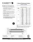
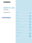
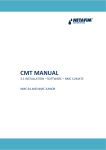
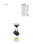
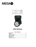
The Cadet
Electric Baseboard
OWNER’S GUIDE
240 Volt Models:
2F350
2F500
3F750
4F1000
5F1250
6F1500
8F2000
8F2500
10F2500
Features & Benefits
• Oversized high temperature limit switch with full length
sensor for added safety
• Durable steel sheathed element with a lifetime warranty
• Rugged steel construction
120 Volt Models:
2F500-1
3F750-1
4F1000-1
6F1500-1
208 Volt Models:
2F500-8
3F750-8
4F1000-8
5F1250-8
6F1500-8
8F2000-8
8F2500-8
Tools Required:
Phillips Screwdriver
Straight Screwdriver
Wire Strippers
Drill or Hammer
Drill Bits
4 Wood Screws
3 Wire Nuts
1 Strain Relief Connector
General Safety Information
WARNING!
Turn the electrical power off at the electrical
panel board (circuit breaker or fuse box) and
lock or tag the panel board door to prevent
someone from turning on power while you
are working on the heater. Failure to do so
could result in serious electrical shock,
burns, or possible death.
1. Read all information labels. Verify that the electrical supply
wires are the same voltage as the heater.
2. All electrical work and materials must comply with the
National Electric Code (NEC), the Occupational Safety and
Health Act (OSHA), and all state and local codes.
3. The heater must be grounded to the grounding pigtail (copper wire) provided.
4. If you need to install a new circuit or need additional wiring
information, consult a qualified electrician.
6.
WARNING
Overheating or fire may occur. DO NOT place the heater
behind doors.
7.
WARNING
Fire or explosion may occur. DO NOT place heater in any
area where combustible vapors, gases, liquids, or excessive lint or dust are present.
8.
WARNING
Risk of Electrical Shock. Turn off all power at the electrical panel board supplying power to the heater before
wiring your heater.
9.
WARNING
Risk of Fire. Heater must be kept clear of all obstructions:
maintain a 12” minimum clearance in front and above the
heater with a 6” minimum on each side. Heaters must be
kept clean of lint, dirt and debris. (See Maintenance
Instructions)
5. Protect electrical supply from kinks, sharp objects, oil,
grease, hot surfaces or chemicals.
Keep For Future Reference
TEL: 360-693-2505 Fax: 360-694-6939 P.O. Box 1675 Vancouver, WA 98668-1675
READ ALL INSTRUCTIONS AND SAFETY
INFORMATION.
Installation Instructions
PLACEMENT: For best results, install the baseboard heater under a window, along an outside wall, or as
close as possible to an outside door.
THERMOSTAT: A thermostat is required. A Cadet by Honeywell wall thermostat is recommended for optimum
WARNING!
RISK OF
ELECTRICAL
SHOCK. TURN OFF
ALL POWER AT
THE ELECTRICAL
PANEL BOARD
SUPPLYING
POWER TO THE
HEATER BEFORE
DOING ANY ELECTRICAL WIRING.
WARNING!
Risk of Fire.
Heater must be
kept clear of all
obstructions: 12
inches in front and
above; 6 inches on
both sides minimum.
performance, or you may prefer the convenience of a BTF-1 or 2 thermostat kit.
STEP 1 AREA OF INSTALLATION
STEP 3 BASEBOARD WIRING
The seam at the junction of the wall and floor
behind the heaters should be caulked to prevent
dust from being drawn into the room. Heaters
should be set flush against surface of the wall.
When installing baseboard heaters, remove any
obstructions between the back of the unit and the
surface of the wall. Keep at least 12" minimum
from objects hanging above (i.e., drapes).
More than one baseboard heater can be wired in
parallel on same circuit (Be sure to check national
and local codes for safety requirements).
STEP 2 MOUNTING HEATER TO WALL
1. Locate wall studs closest to supply wires and position heater. NOTE: Wire connection is possible from
either right or left side of the baseboard heater.
2. Pre-drill mounting holes through the back of the
baseboard case, spacing the holes the distance of
at least two wall studs.
VIEW A
3. Remove the wiring compartment cover.
4. Remove the slotted knockout closest to
the supply wires and install a junction
box connector.
1/ "
2
(13mm)
A
Figure 3.
Disconnect (see Figure 3) splice "B" or "C" (NOT
BOTH). DO NOT disconnect splice "A". Take one
wire from each disconnected lead and connect to
one supply or thermostat lead. Connect remaining
wire from each heater lead and connect to remaining supply or thermostat lead.
240/208 Volt Baseboard Wiring
PRE DRILL IN SHADED AREAS ONLY
IMPORTANT!
It is extremely
important that you
verify the electrical
supply wires are the
same voltage as the
heater (i.e. 120 volt
heater to 120 volt
power supply and
240 volt heater to 240
volt power supply). If
replacing an existing heater, check the
labels of the old
heater and replace
using the same voltage. Hooking a 240
volt heater to a 120
volt power supply
will drastically
reduce the heater's
output. Hooking a
120 volt heater to a
240 volt power supply will destroy the
heater.
C
B
Figure 1.
5. Pull supply wires through the connector leaving 6”
wire leads for connection to the heater wires.
6. Mount the heater securely to the wall with nails or
3-wire hookup - 2 Hot Wires, 1 Ground
(Be sure to check national and local codes for
safety requirements).
Left Side Wiring (See Figure 4)
C
B
STUDS
A
Figure 4.
Disconnect factory splice "A" or "B" (NOT BOTH).
Connect each supply wire (or thermostat wires) to
each lead wire (factory spliced wires).
MOUNT SECURELY TO WALL
Figure 2.
screws going into at least two wall studs. NOTE:
You do not need to remove the element, cover, or
deflector to mount the heater. Baseboard heater may
sit directly on any floor surface, including carpet.
Do not allow carpet to block lower air intake located 1” from the bottom.
7. IMPORTANT: Connect the grounding lead to the
grounding pigtail (copper wire) with a connector.
8. Connect the supply wires to the heater wires.
Right Side Wiring (See Figure 4)
Disconnect factory splice "C". Connect each supply
wire (or thermostat wires) to each lead wire (factory spliced wires).
WARNING!
Risk of Electrical
Shock. Connect
grounding lead to
grounding wire provided. Keep all foreign objects out of
heater.
Installation Instructions
Thermostat Kit Wiring
(Supply wire colors may vary. Reference to colors assumes general standards)
RED WIRE
BTF-1 (See Figure 5)
Connect one supply black wire to the red
thermostat wire. Connect black thermostat
wire to one heater wire. Be sure the other
supply wire is connected directly to heater
wire. Connect ground.
2 RED WIRES
BTF-1
BTF-2
2 BLACK WIRES
Figure 6.
BLACK WIRE
Figure 5.
BTF-2 (See Figure 6)
Connect one each of the supply wires to
one each of the red thermostat wires.
Connect black thermostat wires to remaining (factory spliced) heater wires (see
Figure 4 on previous page).
120 Volt Baseboard Wiring
3-wire hookup - 1 Hot Wire, 1 Neutral, 1 Ground
(Be sure to check national and local codes for safety
requirements)
C
B
Left Side Wiring (See Figure 7)
Disconnect factory splice "A" or "B" (NOT BOTH).
Connect each supply wire (or thermostat wires) to each
lead wire (factory spliced wires).
Right Side Wiring (See Figure 7)
Disconnect factory splice "C". Connect each supply wire
(or thermostat wires) to each lead wire (factory spliced
wires).
A
Figure 7.
WARNING!
Risk of Fire. Heaters
must be kept clean
of lint, dirt and
debris.
Failure to follow
warnings may
cause heater to
eject sparks, ignite
materials, or cause
electrical shock.
RED WIRE
Thermostat Kit Wiring
(Supply wire colors may vary. Our reference to colors assumes general standards)
BTF-1 (See Figure 8)
Connect supply black wire to the red thermostat wire. Connect black thermostat
wire to one heater wire. Check to be sure the other supply wire is connected
directly to heater wire. Connect ground.
BTF-1
BLACK WIRE
Figure 8.
Operation & Maintenance
How To Operate Your Heater
Maintenance
1. Switch the power on at the electrical panel board.
PLEASE NOTE: Upon initial start-up, the heater
may emit a burning odor. This is not dangerous,
and is due to a protective lubricant used during the
manufacturing process.
2. Turn the thermostat fully clockwise.
3. When the room reaches your comfort level, turn
the thermostat knob counterclockwise
until a
clicking sound is heard (if using a digital thermostat, set at desired room temperature). The baseboard will automatically cycle around this preset
temperature.
Cadet electric baseboards are virtually maintenancefree. However, a certain amount of lint and dust will
accumulate inside the unit and should be periodically
cleaned:
1. Turn the electrical power off at the electrical panel
board (circuit breaker or fuse box) and lock or tag
the panel board door to prevent someone from
turning on power while you are working on the
heater. Failure to do so could result in serious electrical shock, burns, or possible death.
2. Remove front panel.
3. Vacuum inside the unit, being careful not to damage the aluminum fins on the heat exchanger.
WARNING!
Turn the electrical
power off at the
electrical panel
board (circuit breaker or fuse box) and
lock or tag the panel
board door to prevent
someone from turning on power while
you are working on
the heater. Failure to
do so could result in
serious electrical
shock, burns, or possible death.
Troubleshooting Chart
CONSULT LOCAL ELECTRICAL CODES TO DETERMINE WHAT WORK MUST BE PERFORMED BY QUALIFIED ELECTRICAL SERVICE PERSONNEL
Symptom
Snapping noise
Problem
Solution
1. Unit may have a loose end plate.
1. Loosen end plate screws 1/4 turn after allowing heater to warm, move end
plate back and forth, then tighten
2. Loosen heater from wall by turning mounting screws a 1/4 turn
2. Heater may not be mounted properly
Heater not working
1. Heater does not have proper voltage
to function correctly
1. Check voltage at the heater between supply wires and make sure it matches
required heater voltage
2. Tighten any loose wire connections
3. Circuit breaker positioned incorrectly - relocate breaker
4. Limit defective - replace limit
Heater will not shut off
1. Heat loss from room is greater than
heater capacity
2. Defective thermostat
1. Close doors and windows. Provide additional insulation, install a higher-wattage
heater or multiple heaters if necessary
2. Adjust thermostat to its lowest setting. If heater continues to run (allow two minutes
for the thermostat to respond), replace thermostat
3. Refer to thermostat documentation and correct wiring
3. Thermostat wired incorrectly to heater
Black streaks (sooting) depositing on baseboard, walls, and
drapes
1. Excessive hydrocarbons present in
home environment*
2. Not enough fresh air flowing through
baseboard
3. Streaking being allowed to build up on
room surfaces
1. Remove/reduce use of items emitting hydrocarbons. (Common sources: insect
foggers, aerosol sprays, carpet cleaning chemicals, candles, plants, dust, cigarette smoke and fireplaces)
2. Increase amount of fresh air available in room. Do not use heater during any
chemical usage (insect fogging, carpet cleaning, etc.) and allow for outside air
exchange before re-use of heater(s)
3. More frequent cleaning of streaking to reduce amount of build-up
* Black soot and residue is formed by the combustion of hydrocarbons. Existing hydrocarbons in environment pass through heater element and scorch, exit the
heater and deposit on walls and room surfaces. Note: The heater itself does not produce/release any hydrocarbons.
Warranty
Warranty Information
Maintenance: For safer operation and to prolong the life of the heater, it is necessary to follow the maintenance instructions included with each heater.
Failure to properly maintain the heater will result in the warranty being voided. All warranties offered to original consumer only. Warranty instructions
included with each heater.
All Cadet Products
LIMITED ONE-YEAR WARRANTY: Cadet Manufacturing Co. will repair or replace any Cadet product, including
thermostats, found to be defective or malfunctioning from first date of purchase through the first year.
Extended Product Warranties
Baseboard Element (F)
LIMITED LIFETIME WARRANTY: Cadet Manufacturing Co. will repair or replace any Cadet baseboard (F) element found to be defective or
malfunctioning from first date of purchase throughout lifetime.
THESE WARRANTIES DO NOT APPLY:
1. To conditions resulting from improper installation or incorrect supply voltage;
2. To conditions resulting from improper maintenance, misuse, abuse, accident, or alteration;
3. To service calls or labor involved in replacing defective part(s);
4. If the date of manufacture cannot be determined;
5. To freight damaged products.
CADET SHALL NOT BE LIABLE FOR DAMAGES SUCH AS PROPERTY DAMAGE AND/OR INCIDENTAL EXPENSES RESULTING FROM BREACH OF THESE
WRITTEN WARRANTIES OR ANY IMPLIED WARRANTY.
These warranties give you specific legal rights, and you may also have other rights which vary from state to state.
Cadet neither assumes, nor authorizes anyone to assume for it, any other obligation or liability in connection with these electric heaters or any part of
such heaters.
If the product should become defective during the warranty period, contact Cadet Manufacturing Co. at 360.693.2505 for instructions on how to have
the repair or replacement processed. Products returned without authorization will be refused.