1
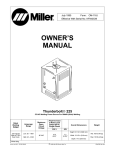
OWNER’S MANUAL
OM-1593
176 877T
Use above FORM number when ordering extra manuals.
2007−08
ICE-12C, ICE-25C, ICE-25CX, ICE-27C, ICE-27T
ICE-40C, ICE-50C, ICE-50CM, ICE-55C, ICE-55CM, ICE-80C, ICE-80CM,
ICE-80CX, ICE-80CXM, ICE-80T, ICE-80TM, ICE-100T, And ICE-100TM Torches
1.
Specifications
Air-cooled torches for plasma arc cutting (PAC)
12 A model: 12 A at 35% duty cycle;
25 A model: 25 A at 35% duty cycle;
27 A model: 27 A at 35% duty cycle;
40 A model: 40 A at 50% duty cycle;
50 A models: 50 A at 60% duty cycle;
55 A model: 55 A at 60% duty cycle;
80 A model: 80 A at 50% duty cycle
100 A model: 100 A at 80% duty cycle
12 A model equipped with 20 ft (6.1 m) cable
25 A model equipped with 15 ft (4.6 m) cable; available with optional 25 ft (7.6 m) cable
27 A model equipped with 20 ft (6.1 m) cable;
40 A model equipped with 25 ft (7.6m) cable; available with optional 50 ft (15.2 m) cable
50 A model equipped with 25 ft (7.6 m) cable; available with optional 50 ft (15.2 m) cable
55 A model equipped with 25 ft (7.6 m) cable; available with optional 50 ft (15.2 m) cable
80 A model equipped with 25 ft (7.6 m) cable; available with optional 50 ft (15.2 m) cable
100 A model equipped with 25 ft (7.6 m) cable; available with optional 50 ft (15.2 m) cable
Use air or nitrogen plasma gas:
12 A model: 1 CFM (28.3 L/min) at 40 PSI (276 kPa);
25 A model: 4.5 CFM (129 L/min) at 60 PSI (414 kPa);
27 A model : 4.5 CFM (129 L/min) at 60 PSI (414 kPa);
40 A model: 6 CFM (170 L/min) at 75 PSI (517 kPa);
50 A model: 5.3 CFM (152 L/min) at 70 PSI (482 kPa);
55 A model: 6 CFM (172 L/min) at 70 PSI (482 kPa);
80 A (C, CM, CX, and CXM) model: 7.2 CFM (207 L/min) at 80 PSI (551 kPa)
80 A (T and TM) model: 7.8 CFM (221 L/min) at 70 PSI (482 kPa)
100 A model: 9.2 CFM (260 L/min) at 75 PSI (517 kPa)
Safety interlock devices shut down power source
12 A, 27 A, 40 A, 50 A, 55 A, 80 A and 100 A models have safety trigger guard
Gear rack pitch for 50 A, 55 A, 80 A and 100A machine-held models: 32
Cutting capacity for mild steel:
12 A model − up to 3/16 in (5 mm) at 12 A;
25 A model − up to 3/8 in (10 mm) at 25 A;
27 A model − up to 3/8 in (10 mm) at 27 A;
40 A model − up to 1/2 in (12.7 mm) at 40 A;
50 A model − up to 7/8 in (22 mm) at 50 A;
55 A model - up to 1 in (25.4 mm) at 55 A;
80 A model − up to 1-1/4 in (32 mm) at 80 A
100 A model − up to 1-1/2 in (38 mm) at 100 A
© 2007 MILLER Electric Mfg. Co.
2.
Safety Symbol Definitions
NOTICE
DANGER! − Indicates a hazardous situation which, if not
avoided, will result in death or serious injury. The possible
hazards are shown in the adjoining symbols or explained
in the text.
Wear safety glasses with side shields.
Indicates a hazardous situation which, if not avoided,
could result in death or serious injury. The possible hazards are shown in the adjoining symbols or explained in
the text.
Cutting processes cause flying pieces of metal and
sparks. Wear a face shield.
Indicates statements not related to personal injury.
Static electricity can damage parts on circuit boards. Put
on grounded wrist strap before touching circuit board.
Indicates special instructions.
3.
Beware of electric shock from the cutting torch or wiring.
Touching the cutting torch while in contact with the work
or ground can cause electric shock. Always wear dry
gloves. Keep all panels and covers closed.
Have only trained and qualified persons install, operate,
or service this unit. Call your distributor if you do not understand the directions. For CUTTING SAFETY and EMF
information, read power source Manual.
Cutting sparks can cause fire or explosion. Move flammables away. Do not cut on closed tanks or barrels −
they can explode. Clean tanks or barrels properly.
Beware of moving parts. Keep guards and panels in
place, covers closed, and hands away from moving parts.
Arc rays can burn eyes and skin − wear face protection
(helmet or face shield) with correct shade of filter, and
cover exposed skin with nonflammable clothing.
Breathing cutting fumes and gases can harm your health.
Cutting requires good ventilation. If ventilation is impossible, such as when cutting in a confined space, use an
air-supplied respirator.
Hot parts can cause burns. Cutting makes parts very hot
− let them cool before touching.
The plasma arc can cause injury. The intense heat of the
arc or pilot arc can cause serious burns. Keep away from
the torch tip when the trigger is pressed. Do not grip material near the cutting path.
Allow cooling period. Reduce current or reduce duty cycle
before starting to cut again. Follow rated duty cycle.
Prolonged noise from some cutting applications can damage hearing. Use approved ear plugs or ear muffs if noise
level is high.
Duty Cycle And Overheating
Duty Cycle is percentage of 10
minutes that unit can cut at rated
load without overheating.
NOTICE − Exceeding duty cycle
can damage power source and
torch and void warranty.
12 Ampere Torch: 35% Duty Cycle At 12 Amperes
25 Ampere Torch: 35% Duty Cycle At 25 Amperes
27 Ampere Torch: 35% Duty Cycle At 27 Amperes
3-1/2 Minutes Cutting
6-1/2 Minutes Resting
40 Ampere Torch: 50% Duty Cycle At 40 Amperes
80 Ampere Torch: 50% Duty Cycle At 80 Amperes
5 Minutes Cutting
5 Minutes Resting
50 Ampere Torch: 60% Duty Cycle At 50 Amperes
55 Ampere Torch: 60% Duty Cycle At 55 Amperes
6 Minutes Cutting
4 Minutes Resting
100 Ampere Torch: 80% Duty Cycle At 100 Amperes
8 Minutes Welding
2 Minutes Resting
rduty1* 5/95
OM-1593 Page 2
4.
Installing 12 Ampere Torch And Work Cable, And Using Trigger Safety Lock
If torch or work cable needs to be
removed or replaced, proceed as
follows:
!
Turn
power
Off,
and
disconnect input power plug
from receptacle.
Remove wrapper from unit.
Torch Connections
5
4
7
8
6
1
Strain Relief
2
Torch Cable
Insert cable through strain relief.
Slide strain relief nut onto torch
cable, but do not tighten.
1
5
Remove existing torch cable from
unit.
3
6
Air Line Connector
Install air line connector onto
compressor fitting.
4
2
Plug PLG4/Receptacle RC4
Connect PLG4 to receptacle RC4
on circuit board PC1.
4
5
2
3
Female And Male Friction
Terminal RC11/ELECT
WHITE
Connect female friction terminal on
end of white leads to RC11/ELECT
WHITE.
3
6
Female And Male Friction
Terminal RC7/PILOT RED
Connect female friction terminal on
end red leads to RC7/PILOT RED.
Tighten strain relief nut.
Tighten strain relief around cable.
Work Cable Connections
Remove existing work cable from
unit.
7
Strain Relief
. Be sure
to allow some work
cable slack inside the unit.
Insert work clamp lead through
strain relief, and install strain relief
into front panel.
8
4
5
8
Work Lead Male Friction
Terminal
Connect work clamp lead to male
friction terminal labeled WORK
LEAD on circuit board PC1. Route
lead along torch lead bundle.
6
9
Trigger
9
Tools Needed:
Trigger Locked
5/8 in
Trigger Unlocked
Ref. 801 300-B / Ref. 802 464 / 199 088 / 801 545-A
801 423 / Ref. 801 300-B
OM-1593 Page 3
5.
Installing 25 Ampere Torch And Work Cable
!
Turn Off power source, and
disconnect input power plug
from receptacle
before
installing torch and work
cable.
Remove top and screws holding
front panel in place. Without disconnecting any plugs, move front panel
to allow access.
8
Torch Connections
8
9
1
Strain Relief Clamp
2
Torch Cable
Insert cable through strain relief
clamp.
2
5
3
13
10
7
Gas Connector
4
Gas Valve
Install gas connector onto gas
valve.
11
6
3
5
Plug PLG18
6
Safety Control Board PC2
7
Receptacle RC18
Connect PLG18 to RC18. Route
leads along existing lead bundle.
8
Female Friction Terminals
9
Male Friction Terminal
10 Power Control Board PC1
11 Receptacle RC4
1
Connect female terminals to leads
23 and 24 from RC4 (connect to
either lead). Connect male terminal
to lead 25 from RC4. Route leads
as shown.
Work Cable Connections
12 Strain Relief Clamp
4
12
Insert work clamp lead through
strain relief clamp.
13 Receptacle RC6
Connect work clamp lead to lead 20
from RC6 (leads not shown). Route
leads along existing lead bundle.
Tools Needed:
5/8 in
801 423 / Ref. 801 300-B
OM-1593 Page 4
6.
Installing 27 Ampere (ICE-27C) Torch And Work Cable, And Using
Trigger Safety Lock
If torch or work cable needs to be
removed or replaced, proceed as
follows:
5
4
8
!
6
7
Turn
power
Off,
and
disconnect input power plug
from receptacle.
Remove wrapper from unit.
Torch Connections
Remove existing torch cable from
unit.
1
5
Strain Relief
2
Torch Cable
Insert cable through strain relief.
Slide strain relief nut onto torch
cable, but do not tighten.
2
6
1
3
Air Line Connector
Insert air line connector into
solenoid fitting.
2
4
4
3
3
5
4
Plug PLG1/Receptacle RC1
Connect PLG1 from torch to
receptacle RC1 on end of wiring
harness connected to circuit board
PC1.
Ring Terminal And Terminal
PILOT
Connect ring terminal on end of red
leads to PILOT terminal.
6
Ring Terminal And Terminal
L2−RED
Connect ring terminal on end of
white leads to L2−RED terminal.
Tighten strain relief nut.
Tighten strain relief around cable.
Work Cable Connections
Remove existing work cable from
unit.
7
Strain Relief
. Be sure
to allow some work
cable slack inside the unit.
Insert work clamp lead through
strain relief, and install strain relief
into front panel.
8
8
5
6
Work Lead Ring Terminal
Connect ring terminal on end of
work clamp lead to terminal labeled
WORK on circuit board PC1. Route
lead along torch lead bundle.
9
Trigger
9
Trigger Locked
Tools Needed:
1/4 in
Trigger Unlocked
Ref. 802 854 / Ref. 802 860 / 200 173-A / 802 877
OM-1593 Page 5
7.
Installing 27 Ampere (ICE-27T) Torch And Work Cable, And Using
Trigger Safety Lock
!
6 4
8
Check DC bus voltage
according to Owner’s Manual,
and be sure voltage is near
zero before touching any
parts.
If torch or work cable needs to be
removed or replaced, proceed as
follows:
5
7
Turn power Off, and disconnect
input power plug from receptacle.
Remove wrapper from unit (see
Owner’s Manual).
2
Torch Connections
Remove existing torch cable from
unit.
1
Strain Relief
Loosen strain relief screw.
2
1
Torch Cable
Insert cable through strain relief,
but do not tighten.
3
Air Line Connector
Insert air line connector into
solenoid fitting. Pull slightly on torch
to set fitting.
4
3
5
6
Plug PLG1/Receptacle RC1
Connect PLG1 from torch to
receptacle RC1 on end of wiring
harness connected to circuit board
PC1.
2
5
4
Ring Terminal And TORCH
WHITE Terminal
Connect ring terminal on end of
white leads to TORCH WHITE
terminal.
6
3
Ring Terminal And TORCH
RED Terminal
Connect ring terminal on end of red
leads to TORCH RED terminal.
Tighten strain relief screw.
Work Cable Connections
Remove existing work cable from
unit.
7
Strain Relief
Loosen strain relief screw.
. Be sure
to allow some work
cable slack inside the unit.
Insert work clamp lead through
strain relief, but do not tighten.
9
8
Trigger Locked
Trigger Unlocked
Work Lead Ring Terminal And
WORK BLACK Terminal
Connect ring terminal on end of
work clamp lead to terminal labeled
WORK BLACK terminal. Route
lead along torch lead bundle.
Tighten strain relief screw.
Reinstall wrapper.
Tools Needed:
9
Trigger
Torx 25
1/4 in
Ref. 804 506-A / Ref. 802 860 / 802 877
OM-1593 Page 6
8.
Installing 40 Ampere Torch And Work Cable
1
3
4
7
6
2
5
8
2
3
5
4
If torch or work cable needs to be removed
or replaced, proceed as follows:
!
Turn power Off, and disconnect
input power plug from receptacle.
Remove wrapper from unit.
Torch Replacement
1
Strain Relief
2
Torch Cable
Loosen outer strain relief pigtail so that
torch cable can slide freely.
3
Plug PLG1/Receptacle RC1
Disconnect PLG1 from receptacle RC1 on
Control board PC1.
4
Plug PLG11/Receptacle RC11
back of strain relief.
Slide torch cable, connector, and plugs
through nut and out of unit. Retain nut for
use on replacement strain relief.
Insert replacement cable with strain relief
through opening where old cable and strain
relief were removed. Slide strain relief nut
over plugs, connector, and cable. Install nut
onto strain relief, but do not tighten.
Insert air line connector into solenoid fitting.
Connect PLG1 to RC1 on Control board
PC1.
Connect PLG11 to RC11 on Control board
PC1.
Tighten strain relief nut.
Disconnect PLG11 from receptacle RC11
on Control board PC1.
Tighten strain relief around cable.
5
6
7
Air Line Connector
Push orange fitting inward toward air
solenoid while pulling connector out of
fitting.
Remove nut, located inside of unit, from
Work Cable Replacement
Rubber Boot
Work Cable Ring Terminal
Slide rubber boot away from ring terminal
connection on Control board PC1. Remove
hardware securing ring terminal to PC1.
8 Strain Relief
Remove nut, located inside of unit, from
back of strain relief.
Slide work cable through nut and out of unit.
Retain nut for use on replacement strain
relief.
Slide rubber boot over ring terminal and off
of work cable. Retain rubber boot for use on
replacement work cable.
. Be
sure to allow some work cable
slack inside the unit.
Insert replacement cable with strain relief
through opening where old cable and strain
relief were removed. Slide strain relief nut
over ring terminal and cable. Install nut onto
strain relief, but do not tighten.
Route cable along bottom of unit and up to
PC1.
Slide rubber boot over ring terminal and
onto work clamp lead. Connect work cable
ring terminal to terminal labeled WORK on
circuit board PC1. Torque to 35 in lb
(4 N⋅m). Slide boot over connection.
Tighten strain relief nut.
Tighten strain relief around cable.
Tools Needed:
5/16, 3/8 in
803 386 / 803 385
OM-1593 Page 7
9.
Installing 50 Ampere, 55 Ampere or 80 Ampere Torch And Using Trigger Safety Lock
. The 50 ampere torch is shown in the illustrations below.
!
Turn Off power source, and
disconnect input power plug
from receptacle
before
installing torch.
1
Power Source
2
Torch Connection Receptacle
3
Plug
4
Threaded Collar
5
Keyway
The procedure for the 55 ampere and 80 ampere
torches is identical.
. The 55 ampere torch can be used on a 50 ampere model
power source. The 50 ampere torch cannot be used on
a 55 ampere model power source. The 55 ampere power source has a special torch connection receptacle that
prevents the 50 ampere torch from being connected.
To connect to receptacle, align
keyway, insert plug, and tighten
threaded collar.
5
6
Trigger
1
4
3
NOTICE − Be sure plug is correctly
aligned before tightening collar to
avoid cross-threading.
2
6
Trigger Locked
Trigger Unlocked
801 395-A / 801 545-A
OM-1593 Page 8
10. Installing Either 80 Ampere Or 100 Ampere T/TM Torch
2
1
3
!
Turn off power source and
disconnect input power.
1
2
3
4
5
Torch Connector
Quick Connect Collar
Nipple
Receptacle
Securing Pin
To connect torch:
Push torch connector onto
receptacle and quick connect until
collar secures nipple.
Rotate securing pin to lock
connector to unit.
4
5
To disconnect torch:
Rotate securing pin to unlock
connector from unit.
Push quick connect collar back
towards unit to release nipple, and
pull torch connector away from unit.
804 055-A
OM-1593 Page 9
11. Sequence Of Operation For 12 Ampere Torch
. Moisture from the compressor will form in the air line and at
EXAMPLE Of Cutting Operation
the torch. It will be normal to sometimes see moisture come
out the end of the torch.
!
The pilot arc starts immediately when trigger is pressed.
For shielded cutting, place drag shield on edge
of metal. For non-shielded cutting (non-CE
only), use 1/8 in (3.2 mm) standoff distance
(dragging tip will reduce tip life).
Adjust torch speed so
sparks go thru metal and
out bottom of cut.
Raise trigger lock and press
trigger. Pilot arc starts.
Pause briefly at end of
cut before releasing trigger.
After cutting arc starts, slowly
start moving torch across metal.
Postflow continues for approx. 12 seconds
after releasing trigger; cutting arc can be instantly restarted during postflow by raising
trigger lock and pressing trigger.
801 400-A
OM-1593 Page 10
12. Sequence Of Operation For 27 Ampere Torch
EXAMPLE Of Cutting Operation
!
The pilot arc starts immediately when trigger is pressed.
Place tip on work for drag cutting.
. For maximum cutting speed and tip life,
Raise trigger lock and press
trigger. Pilot arc starts.
After cutting arc starts, slowly
start moving torch across metal.
use a standoff distance of 1/16 in (1.6
mm) to 1/8 in (3.2 mm). Dragging tip will
reduce tip life.
Adjust torch speed so
sparks go thru metal and
out bottom of cut.
Pause briefly at end of
cut before releasing trigger.
Postflow continues for 20 seconds after
releasing trigger; cutting arc can be instantly
restarted during postflow by raising trigger
lock and pressing trigger.
Ref. 802 878
OM-1593 Page 11
13. Sequence Of Operation For 25, 40, 50, 55, 80, And 100 Ampere Torches
!
Inspect shield cup, tip, and electrode for wear before cutting or whenever cutting speed has been
significantly reduced (see Section 17). Do not operate torch without a tip or electrode in place.
NOTICE − Do not clean torch by hitting it against a hard
surface. Hitting hard surfaces can damage torch parts
and stop proper operation.
Install &
Connect
Equipment
Put On Personal
Safety
Equipment
Check Torch Tip,
Electrode, And
Retaining Cup
NOTICE − Having pilot arc turn On and Off repeatedly,
such as during the cutting of chain fence, will shorten tip,
electrode and torch life. Put a continuous piece of sheet
metal under the fence to prevent pilot arc from cycling On
and Off. Avoid constant starting and restarting of arc.
Check Gas/Air
Pressure
Set
Controls
Turn On
Power Source
Begin
Cutting
EXAMPLE Of Cutting Operation
!
For 25 ampere torch, place tip on
edge of metal.
The pilot arc starts immediately when trigger is pressed.
Press trigger. Pilot arc starts.
After cutting arc starts, slowly
start moving torch across metal.
For 40, 50, 80 and 100 ampere
hand-held torches, place drag
shield on edge of metal, or allow
correct standoff distance −
approximately
1/8 in (3.2 mm).
Adjust torch speed so
sparks go thru metal and
out bottom of cut.
Pause briefly at end of
cut before releasing trigger.
Postflow continues for approx. 20 to
30 seconds after releasing trigger;
cutting arc can be instantly restarted during postflow by pressing
trigger.
161 698-A
OM-1593 Page 12
14. Routine Maintenance
!
n = Check
Z = Change
~ = Clean
* To be done by Factory Authorized Service Agent
Turn Off power source
and disconnect
input power plug
before maintaining.
. 25 ampere torch is shown.
Maintenance schedule for
50 and 80 ampere torches is the same.
l = Replace
Reference
Each
Use
n Check Gas/Air Pressure
Every
Week
Every
3
Months
n Torch Tip, Electrode,
And Shield Cup
n Shield Cup Shutdown
System
l Cracked Parts
n Gas/Air Hose
n Torch Body, Cable
n Tape Torn Outer
Covering
15. Shield Cup Shutdown System
1
. Power source Power switch must be reset whenever cup shutdown
system is activated. Always turn Off power source when changing or
checking consumables.
Torch Shield Cup
Turn Power On and loosen shield
cup. If shutdown system works
properly, Ready light on power
source goes off and Cup light comes on. If not, turn power Off and
check for proper gas/air pressure,
blocked or leaking hose, or loose
shield cup.
If system works properly, retighten
cup and reset power.
1
1
. Procedure applies to all torch models.
Ref. 801 300-A / Ref. 801 300-A
OM-1593 Page 13
16. Checking/Replacing Retaining Cup, Tip, And Electrode For 12 And 27 Ampere Torch
!
Inspect shield cup, tip, and electrode for wear before cutting or whenever
cutting speed has been significantly reduced. Do not operate torch without a tip or electrode in place. Be sure to use genuine replacement parts.
NOTICE − Overtightening will strip threads. Do not overtighten retaining cup
during assembly. Do not cross-thread parts causing stripping. Use care
during torch assembly and parts replacement.
. A good practice is to replace both the tip and electrode at the same time.
!
Turn Off power source before checking torch
parts.
Make sure this area is clean of
any debris.
8
6
Make sure swirl ring is clean of any
debris and no holes are
obstructed.
5
7
4
3
New
*Pit
Depth
1
New
2
Worn
*1/32 in (1 mm) — 1/16 in (2 mm)
maximum pit depth depending on
acceptable cut quality.
Worn
802 465
Turn Off power source.
1 Shield Cup
2 O-Ring
Remove shield cup. Check cup for cracks,
and replace if necessary.
Check O-ring for cracks or worn spots, replace shield cup if necessary.
3 Tip
4 Opening
OM-1593 Page 14
Remove tip. Check tip, and replace if opening is deformed or 50% oversize. If inside of
tip is not clean and bright, clean with steel
wool. Be sure to remove any pieces of steel
wool afterwards.
5 Electrode
Check electrode. If center has a pit more
than a 1/16 in (2 mm) deep, remove and replace electrode.
6 Swirl Ring
7
O-Ring
Remove swirl ring. Check ring, and replace
if side holes are plugged.
Check O-ring for cracks or worn spots,
replace swirl ring if necessary.
8 O-Ring
Check O-ring for cracks or worn spots, and
replace if necessary.
Carefully reassemble parts in reverse order.
17. Checking/Replacing Retaining Cup, Tip, And Electrode For 25, 40, 50, And 55
Ampere Torches
!
Inspect shield cup, tip, and electrode for wear before cutting or whenever
cutting speed has been significantly reduced. Do not operate torch without
a tip or electrode in place. Be sure to use genuine replacement parts.
NOTICE − Overtightening will strip threads. Do not overtighten electrode, tip,
and retaining cup during assembly. Do not cross-thread parts causing stripping. Use care during torch assembly and parts replacement.
. A good practice is to replace both the tip and electrode at the same time.
!
Turn Off power source before checking torch parts.
50 Ampere and 55 Ampere Models
25 Ampere Model
8
5
Make sure this area is clean of
any debris.
7
7
6
New
5
8
6
New
*Pit
Depth
The word “front” on swirl ring must
face away from torch body.
*Pit
Depth
Make sure swirl ring is clean of any
debris and no holes are
obstructed.
Worn
Worn
*1/32 in (1 mm) — 1/16 in (2 mm)
maximum pit depth depending on
acceptable cut quality.
4
3
4
2
3
2
New
New
1
Worn
Worn
Ref. 801 301 / 801 139 / Ref. 801 396-A / 801 405
Turn Off power source.
1 Drag Shield
2 Retaining Cup
Remove retaining cup. Check retaining cup
for cracks, and replace if necessary.
3 Tip
4 Opening
Remove tip. Check tip, and replace if opening is deformed or 50% oversize. If inside of
tip is not clean and bright, clean with steel
wool. Be sure to remove any pieces of steel
wool afterwards.
5 Electrode
Check electrode. If center has a pit more
than a 1/16 in (2 mm) deep, remove and replace electrode.
6 Swirl Ring
Remove swirl ring. Check ring, and replace
if side holes are plugged.
7 O-Ring
Check O-rings on torch. If needed, coat with
thin film of silicone lubricant (part no.
169 231). Replace if damaged.
8
Plunger Area
Check this area for any debris or foreign material. Clean out if necessary.
Carefully reassemble parts in reverse order.
For the 25 ampere model, swirl ring must be
installed with word “front” facing away from
torch body.
OM-1593 Page 15
18. Checking/Replacing Retaining Cup, Tip, And Electrode For 80 Ampere (C/CM) Torch
!
Inspect shield cup, tip, and electrode for wear before cutting or whenever
cutting speed has been significantly reduced. Do not operate torch without a tip or electrode in place. Be sure to use genuine replacement parts.
NOTICE − Overtightening will strip threads. Do not overtighten electrode, tip,
and retaining cup during assembly. Do not cross-thread parts causing stripping. Use care during torch assembly and parts replacement.
. A good practice is to replace both the tip and electrode at the same time.
!
Turn Off power source before checking torch parts.
80 ampere model requires
electrode wrench 189 086
5
Make sure this area is clean of
any debris.
8
7
6
*1/32 in (1 mm) — 1/16 in (2 mm)
maximum pit depth depending on
acceptable cut quality.
New
Make sure swirl ring is clean of
any debris and no holes are
obstructed.
*Pit
Depth
Worn
2
4
1
3
New
Worn
803 612-A
Turn Off power source.
1
Drag Shield
2
Retaining Cup
Remove retaining cup. Check retaining cup
for cracks, and replace if necessary.
3
Tip
4
Opening
Remove tip. Check tip, and replace if open-
OM-1593 Page 16
ing is deformed or 50% oversize. If inside of
tip is not clean and bright, clean with steel
wool. Be sure to remove any pieces of steel
wool afterwards.
5
Electrode
Check electrode. If center has a pit more
than a 1/16 in (2 mm) deep, remove and replace electrode.
6
Swirl Ring
Remove swirl ring. Check ring, and replace
if side holes are plugged.
7 O-Ring
Check O-rings on torch. If needed, coat with
thin film of silicone lubricant (part no.
169 231). Replace if damaged.
8 Torch Head
Check this area for any debris or foreign material. Clean out if necessary.
Carefully reassemble parts in reverse order.
19. Checking/Replacing Retaining Cup, Tip, And Electrode For 80 Ampere (CX/CXM/
T/TM, And 100 T/TM) Torch
!
Inspect shield cup, tip, and electrode for wear before cutting or whenever
cutting speed has been significantly reduced. Do not operate torch without a tip or electrode in place. Be sure to use genuine replacement parts.
NOTICE − Overtightening will strip threads. Do not overtighten electrode,
tip, and retaining cup during assembly. Do not cross-thread parts causing
stripping. Use care during torch assembly and parts replacement.
. A good practice is to replace both the tip and electrode at the same time.
!
Turn Off power source before checking torch parts.
1/32 in
(1 mm)
Pit
5
Worn
New
Make sure this area is
clean of any debris.
3
Worn
8
7
New
4
6
Make sure this area is
clean of any debris.
2
1
804 056-A
Turn Off power source.
1 Drag Shield
Check this area for any debris or foreign
material. Clean out if necessary.
2 Retaining Cup
Remove retaining cup. Check retaining cup
for cracks, and replace if necessary.
3
4
Tip
Opening
Remove tip. Check tip, and replace if opening is deformed or 50% oversize. If inside of
tip is not clean and bright, clean with steel
wool. Be sure to remove any pieces of steel
wool afterwards.
5
Electrode
Check electrode. If center has a pit more
than a 1/32 in (1 mm) deep, remove and
replace electrode.
6
Swirl Ring
Remove swirl ring. Check ring, and replace
if side holes are plugged.
7 O-Ring
Check O-rings on torch. If needed, coat with
thin film of silicone lubricant (part no.
169 231). Replace if damaged.
8 Plunger Area
Check this area for any debris or foreign
material. Clean out if necessary.
Carefully reassemble parts in reverse order.
OM-1593 Page 17
20. Troubleshooting For 12 Ampere Torch
Does arc go
on and off
while cutting?
Yes
Torch travel speed too slow;
increase travel speed (see
Power Source Owner’s
Manual). Clean or replace
torch consumables as
necessary (see Section 16).
Be sure work clamp is
securely
attached
to
workpiece.
See Power Source Owner’s
Manual.
No
Does arc go out
while cutting?
Yes
Be sure work clamp is
securely attached to workpiece. Make sure drag
shield contacts metal while
cutting. Clean or replace
torch consumables as
necessary (see Section 16).
See Power Source Owner’s
Manual.
No
Do sparks come
out of top of cut;
or cut is not
clean?
Yes
Torch travel speed too fast;
reduce travel speed (see
Power Source Owner’s
Manual). Clean or replace
torch consumables as
necessary (see Section 16).
Be sure work clamp is
securely
attached
to
workpiece. Unit not capable
of cutting metals thicker
than rating (see Section 1).
No
Is Trouble light
On; unit has no
cutting output?
Yes
Check torch shield cup (see
Section 15); reset unit
Power switch. *Check torch
and connections inside unit.
See Power Source Owner’s
Manual.
No
See Power Source Owner’s
Manual.
*Servicing procedure to be performed
only by authorized Service Station.
OM-1593 Page 18
21. Troubleshooting For 25, 27, 40, 50, 55, 80, And 100 Ampere Torches
Trouble
Remedy
Power source Cup trouble light On; no Tighten cup onto torch and reset Power (see Section 15).
cutting output.
Check torch connections on power source. See power source Owner’s Manual.
Sparks come out top of cut, or cut is not Torch travel speed too fast; reduce travel speed (see Section 13).
clean.
Clean or replace worn consumables as necessary (see Section 17).
Metal being cut is too thick; increase output control setting. See power source Owner’s Manual.
Be sure work clamp is securely attached. See power source Owner’s Manual.
Arc goes out while cutting.
Make sure torch tip is contacting metal while cutting.
Be sure work clamp is securely attached. See power source Owner’s Manual.
Clean or replace worn consumables as necessary (see Section 17).
Arc goes on and off while cutting.
Torch travel speed is too slow; increase travel speed (see Section 13).
Clean or replace worn consumables as necessary (see Section 17).
Be sure work clamp is securely attached. See power source Owner’s Manual.
OM-1593 Page 19
22. Parts Lists
Item Part
No. No.
1
2
1
183 427
2
3
4
5
6
171 248
196 931
196 930
196 932
185 833
190 220
169 231
196 923
3
6
5
Description
Handle Assy, left and right
w/screws (1)
Pushbutton Switch (1)
Leads, 20ft (1)
Label, ICE-12C (1)
Main Body (1)
Switch Assy w/Spring (1)
Spring, trigger assy (1)
Grease, silicone (1)
Torch, replacement 20ft (1)
1
4
See Figure 22-2 for additional
consumable parts.
Figure 22-1. Torch, ICE-12C
Drag
Shield
196929
Retaining
Cup
197567
Swirl
Tip
Electrode
Ring
196926 196925 196927
O−Ring
196935
Apply silicone
grease(169231)
before installing.
Retaining
Cup
196928
1/8”(3mm)
stand−off
recommended
CAUTION
FAILURE TO RE−
PLACE WORN TIP
OR ELECTRODE
WILL RUIN TORCH
AND VOID
WARRANTY.
S Turn off power
ICE−12C
CONSUMABLES
S
before
checking torch parts.
Check before each
use and hourly
during operation.
206 304
206 304
Figure 22-2. Consumable Parts For ICE-12C
OM-1593 Page 20
1
Item Part
No. No.
1
2
2
3
4
2
183 428
177 893
177 894
178 550
171 248
169 231
195 007
Description
Handle Assy, complete (1)
Leads, 15ft (1)
Leads, 25ft (1)
Main Body (1)
Push Button Switch (1)
Grease, silicone (1)
Torch, replacement 20ft (1)
4
3
1
See Figure 22-4 for additional
consumable parts.
2
Ref. 801 300-B
Figure 22-3. Torch, ICE-25C
O-ring
169232
Electrode
176655
Retaining
Cup
202808
Swirl Ring
202809
Tip 176656
Ref. 178 744
Figure 22-4. Consumable Parts For ICE-25C
OM-1593 Page 21
1
Item Part
No. No.
2
3
1
2
3
4
5
183 427
171 248
205 881
203 119
185 833
190 220
169 231
195 007
5
Description
Handle Assy, complete (1)
Push Button Switch (1)
Leads, 20ft (1)
Main Body (1)
Switch Assembly
w/spring (1)
Spring, trigger assembly
Grease, silicone (1)
Torch, replacement 20ft (1)
1
4
See Figure 22-6 for additional
consumable parts.
3
Ref. 801 300-B
Figure 22-5. Torch, ICE-25CX
ICE-25CX
Consumables
Ref. 202 108-A
Figure 22-6. Consumable Parts For ICE-25CX
OM-1593 Page 22
Item Part
No. No.
1
2
1
2
3
4
5
3
183 427
171 248
203 120
203 119
185 833
190 220
169 231
195 014
5
Description
Handle Assy, complete (1)
Push Button Switch (1)
Leads, 20ft (1)
Main Body (1)
Switch Assembly
w/spring (1)
Spring, trigger assembly
Grease, silicone (1)
Torch, replacement 20ft (1)
1
4
See Figure 22-8 for additional
consumable parts.
Figure 22-7. Torch, ICE-27C
202 108-A
Figure 22-8. Consumable Parts For ICE-27C
OM-1593 Page 23
1
2
3
Item
No.
Part
No.
1
2
3
4
5
183 427
171 248
228 405
203 119
185 833
190 220
169 231
225 615
5
Description
Handle Assy, complete (1)
Push Button Switch (1)
Leads, 12 ft (1)
Main Body (1)
Switch Assembly
w/spring (1)
Spring, trigger assembly
Grease, silicone (1)
Torch, replacement 12 ft (1)
1
4
See 22-10 for
additional consumable parts.
Figure 22-9. Torch, ICE-27T
Retaining
Cup
202808
Drag
Shield
225616
RetainCup,
DragShield
225672
ICE−27C/T
CONSUMABLES
Tip
176656
Electrode
176655
Swirl
Ring
202809
O−Ring
169232
Tip,Drag
Shield
225671
CAUTION
FAILURETORE−
PLACEWORNTIP
ORELECTRODE
WILLDAMAGE
TORCHANDVOID
WARRANTY.
Turnoffpowerbefore
checkingtorchparts.
Checkbeforeeach
useandhourly
duringoperation.
228449−A
228 449-A
Figure 22-10. Consumable Parts For ICE-27C/T
OM-1593 Page 24
Item Part
No. No.
1
Description
6
1
2
3
3
4
5
4
195 110
195 111
183 427
192 059
209 298
209 299
185 833
5
6
2
ICE-40C 25ft Torch
ICE-40C 50ft Torch
Handle Assy, complete (1)
Main Body (1)
Leads, 25ft (1)
Leads, 50ft (1)
Switch Assembly
w/spring (1)
Spring, trigger assembly
Push Button Switch (1)
Grease, silicone (1)
190 220
171 248
169 231
1
See Figure 22-12 for additional
consumable parts.
3
Ref. 803 386
Figure 22-11. Torch, ICE-40C
For extended tip use, set
Amperage control to 35.
Drag Shield
204 323
Retaining Cup
192 050
Tip
204 325
Electrode
192 047
Swirl Ring
192 049
Standard
Cutting
Deflector
177 888
Shield
192 203
Retaining Cup
192 050
Retaining Cup
192 050
35A Tip
192 052
Tip
204 332
Electrode
192 048
Extended
Cutting
Electrode
192 047
O−Ring
169 232
Apply silicone
grease (169 231)
before installing.
1/8” (3mm)
stand−off
recommended
Gouging
CAUTION
NOTE:
Set air pressure to
75 PSI for cutting
or 55 PSI for gouging.
ICE−40C
CONSUMABLES
FAIL URE TO RE−
PLACE WORN TIP
OR ELECTRODE
WILL RUIN TORCH
AND VOID
WARRANTY .
•
•
Turn off power before
checking torch parts.
Check before each
use and hourly
during operation.
207 686−A
207 686-A
Figure 22-12. Consumable Parts For ICE-40C
OM-1593 Page 25
Item Part
No. No.
1
2
3
3
4
5
1
2
3
183 427
171 248
179 829
179 830
188 794
185 833
190 220
169 231
176 824
176 826
Description
Handle Assy, complete (1)
Push Button Switch (1)
Leads, 25ft (1)
Leads, 50ft (1)
Main Body (1)
Switch Assembly
w/spring (1)
Spring, trigger assembly
Grease, silicone (1)
Torch, replacement 25ft (1)
Torch, replacement 50ft (1)
5
1
4
See Figure 22-14 for
additional consumable parts.
Figure 22-13. Torch, ICE-50C
Ref. S-180 338-C
Figure 22-14. Consumable Parts For ICE-50C And 50CM
OM-1593 Page 26
Item Part
No. No.
1
2
3
4
5
6
7
8
192 050
169 232
180 343
180 610
180 342
180 605
180 611
192 058
169 231
176 828
Description
Cup, shield (1)
O-Ring, 55A (1)
Main Body (1)
Position Sleeve (1)
Leads, 50ft (1)
Remote Pendent Control (1)
Torch Sleeve (1)
Shield, machine (1)
Grease, silicone (1)
Torch, replacement 50ft (1)
5
4
3
2
1
7
6
See Figure 22-14 for
additional consumable parts.
8
Figure 22-15. Torch, ICE-50CM
OM-1593 Page 27
Item Part
No. No.
1
2
3
1
2
3
3
4
183 427
171 248
192 062
192 063
192 059
202 932
5
185 833
190 220
169 231
193 347
193 348
5
Description
Handle Assy, complete (1)
Push Button Switch (1)
Leads, 25ft (1)
Leads, 50ft (1)
Main Body (1)
Plunger Kit (for
out-of-warranty torches)
Switch Assembly
w/spring (1)
Spring, trigger assembly
Grease, silicone (1)
Torch, replacement 25ft (1)
Torch, replacement 50ft (1)
1
4
See Figure 22-17 for
additional consumable parts.
Figure 22-16. Torch, ICE-55C
Ref. 193 356-A
Figure 22-17. Consumable Parts For ICE-55C And 55CM
OM-1593 Page 28
Item Part
No. No.
1
2
3
4
5
6
7
8
9
1
Description
192 050
169 232
192 060
180 610
192 061
180 605
198 643
192 058
198 644
169 231
193 349
Cup, shield (1)
O-Ring, 55A (1)
Main Body (1)
Position Sleeve (1)
Leads, 50ft (1)
Remote Pendent Control (1)
Torch Sleeve (1)
Shield, machine (1)
Ring, retaining (1)
Grease, silicone (1)
Torch, replacement 50ft (1)
3
2
4
9
5
7
8
See Figure 22-17 for
additional consumable parts.
6
Figure 22-18. Torch, ICE-55CM
OM-1593 Page 29
Item Part
No. No.
1
2
3
187 300
190 502
190 503
4
196 682
190 504
187 301
187 298
177 902
5
6
7
Item Part
No. No.
Description
8
8
9
Handle (1)
Boot (1)
#6 x 5/8 Philips Screw,
pan head (5)
Trigger and Switch
Replacement Kit (1)
spring (1)
Switch, cup sensor (1)
Main Body (1)
O-Ring,
silicon .864 x .070 (1)
Description
196 415
196 416
190 497
187 305
190 500
190 501
176 830
176 832
10
11
Torch Lead, 25ft (1)
Torch Lead, 50ft (1)
Plug Assy,
quick disconnect (1)
O-Ring, quick disconnect (1)
Tubing, 5/8 in ID (4in) (1)
Heatshrink 1/2 in ID (2.5in) (1)
Torch, replacement 25ft (1)
Torch, replacement 50ft (1)
9
2
1
10
8
4
4
6
1
11
7
5
3
. Older model torches using trigger 187 302 and
pushbutton switch 171 248 should be updated using trigger and switch replacement kit 196 682.
See Figure 22-20 for
additional consumable parts.
Figure 22-19. Torch, ICE-80C
Electrode
Wrench
189 086
Ref. S-188 942-A
Figure 22-20. Consumable Parts For ICE-80C And 80CM
OM-1593 Page 30
Item Part
No. No.
1
2
3
180 610
196 417
190 497
4
5
6
187 305
190 498
187 299
177 902
7
8
9
Sleeve, torch position (1)
Torch Lead, 50ft (1)
Plug Assy,
quick disconnect (1)
O-Ring, quick disconnect (1)
Plug, 3-socket female (1)
Main Body (1)
O-Ring,
silicon .864 x .070 (1)
Contact, cap-on sensor (2)
Tubing, 5/8 in ID (4in) (1)
Heatshrink 1/2 in ID (2.5in) (1)
Torch, replacement 50ft (1)
190 499
190 500
190 501
176 834
2
4
Description
3
See Figure 22-20 for
additional consumable parts.
7
8
5
6
1
8
2
Figure 22-21. Torch, ICE-80CM
OM-1593 Page 31
Item Part
No. No.
1
2
3
4
5
6
7
8
8
215 594
215 478
215 479
185 833
190 220
215 592
215 477
216 309
218 045
Item Part
No. No.
Description
9
10
11
12
Handle w/Screws (1)
Cup Switch Sensor Kit (1)
Torch Head Repair Kit (1)
Switch Assy w/Spring (1)
Trigger Spring (1)
Switch Trigger (1)
Main Body (1)
Torch Lead, 25ft (1)
Torch Lead, 50ft (1)
9
1
215 606
187 305
212 735
218 177
169 231
216 300
218 044
Description
Clip, retaining (1)
O-Ring, quick disconnect (2)
O-Ring, main body (1)
Plug Assy, quick disconnect (1)
Grease, silicon
Torch, replacement 25ft (1)
Torch, replacement 50ft (1)
8
10
12
2
6
7
3
5
11
1
4
See Figure 22-23 for
additional consumable parts.
Figure 22-22. Torch, ICE-80CX
40A
StandardCutting
Retaining
Tip
DragShield
Cup
212733 212725
212730
Shield
212732
ExtendedCutting
40A
Retaining
80A
Deflector
212736
80A
Shield
212731
Cup
212733
Tip
212729
Retaining
Cup
212733
Tip
212728
O−Ring
212735
ICE−80CX
CONSUMABLES
CAUTION
FAILURETORE−
PLACEWORNTIP
ORELECTRODE
WILLRUINTORCH
ANDVOID
WARRANTY.
• Turnoffpowerbefore
checkingtorchparts.
• Checkbeforeeach
Gouging
Retaining
Cup
212733
SwirlRing
212734
Applysilicone
grease(169231)
beforeinstalling.
(Machine
Cutting)
80A
Retaining
DragShield
Cup
Tip
212730
212733 212726
Deflector
212736
Electrode
212724
Tip
212727
useandhourly
duringoperation.
218443−A
218 443-A
Figure 22-23. Consumable Parts For ICE-80CX
OM-1593 Page 32
Item Part
No. No.
1
2
3
4
5
6
7
Description
215 607
219 964
218 177
190 498
215 599
215 598
187 305
219 944
Sleeve, torch position (1)
Torch Lead, 50ft (1)
Plug Assy, quick disconnect (1)
Plug, 3 socket female (1)
Torch Sleeve (1)
Main Body w/Switch (1)
O-ring, quick disconnect (2)
Torch, replacement 50ft (1)
1
4
7
2
3
6
5
See Figure 22-23 for
additional consumable parts.
Figure 22-24. Torch, ICE-80CXM
Item Part
No. No.
1
2
3
4
5
6
7
8
8
Item Part
No. No.
Description
215 594
215 478
215 479
185 833
190 220
215 592
215 477
223 543
223 544
Handle w/Screws (1)
Cup Switch Sensor Kit (1)
Torch Head Repair Kit (1)
Switch Assy w/Spring (1)
Trigger Spring (1)
Switch Trigger (1)
Main Body (1)
Torch Lead, 25ft (1)
Torch Lead, 50ft (1)
9
10
11
215 606
212 735
169 231
195 223
195 225
227 546
Description
Clip, retaining (1)
O-Ring, main body (1)
Grease, silicon
Torch, replacement 25ft (1)
Torch, replacement 50ft (1)
Wing Head 1/4 Turn Fastener (1)
8
11
9
1
See Figure 22-23 for
additional consumable parts.
2
7
6
3
5
10
4
1
804 035-A
Figure 22-25. Torch, ICE-80T
OM-1593 Page 33
80A
StandardCutting
Retaining
DragShield
Cup
Tip
212730
212733 212726
Shield
212732
Electrode
212724
SwirlRing
212734
Applysilicone
grease(169231)
beforeinstalling.
(Machine
Cutting)
ICE−80T
CONSUMABLES
40A
Retaining
DragShield
Tip
Cup
212733 212725
212730
CAUTION
ExtendedCutting
80A
Retaining
Deflector
212736
40A
Deflector
212736
80A
Shield
212731
Cup
212733
Tip
212728
Retaining
Cup
212733
Tip
212729
FAILURETORE−
PLACEWORNTIP
ORELECTRODE
WILLRUINTORCH
ANDVOID
WARRANTY.
Turnoffpowerbefore
checkingtorchparts.
Checkbeforeeach
useandhourly
duringoperation.
Gouging
Retaining
Cup
212733
O−Ring
212735
Tip
212727
213031−B
213 031-B
Figure 22-26. Consumable Parts For ICE-80T
Item Part
No. No.
1
2
2
3
4
5
6
7
215 607
223 545
223 546
215 599
215 598
195 513
195 221
223 535
220 240
220 241
227 546
215 478
See Figure 22-23 for
additional consumable parts.
Description
Sleeve, torch position (1)
Torch Lead, 25ft (1)
Torch Lead, 50ft (1)
Torch Sleeve (1)
Main Body (1)
Remote Pendant Control (1)
Torch, replacement 25ft (1)
Torch, replacement 50ft (1)
Cable, remote control trigger 25ft (1)
Cable, remote voltage sense 26.5ft (1)
Wing Head 1/4 Turn Fastener (1)
Cup Switch Sensor Kit (1)
1
6
2
7
5
4
3
804 036-A
Figure 22-27. Torch, ICE-80TM
OM-1593 Page 34
Item Part
No. No.
1
2
3
4
5
6
7
8
8
Item Part
No. No.
Description
215 594
215 478
223 775
185 833
190 220
215 592
223 774
223 612
223 613
9
10
Handle w/Screws (1)
Cup Switch Sensor Kit (1)
Torch Head Repair Kit (1)
Switch Assy w/Spring (1)
Trigger Spring (1)
Switch Trigger (1)
Main Body (1)
Torch Lead, 25ft (1)
Torch Lead, 50ft (1)
11
215 606
212 735
169 231
225 702
225 704
227 546
Description
Clip, retaining (1)
O-Ring, main body (1)
Grease, silicon
Torch, replacement 25ft (1)
Torch, replacement 50ft (1)
Wing Head 1/4 Turn Fastener (1)
8
11
9
1
See 22-23 for
additional consumable parts.
2
7
6
3
5
10
4
1
804 035-A
Figure 22-28. Torch, ICE-100T
OM-1593 Page 35
CAUTION
Drag Shield
Retaining Cap
Tip
Electrode
FAILURETORE−
PLACEWORNTIP
ORELECTRODE
WILLRUINTORCH
ANDVOID
WARRANTY.
Swirl Ring
Turnoffpowerbefore
checkingtorchparts.
Checkbeforeeach
useandhourly
duringoperation.
40A
212 730
212 733
212 725
212 730
212 733
219 676
212 730
212 733
212 726
219 685
219 684
219 679
60A
212 724
212 734
O-Ring
212 735
80A
100A
219 678
219 677
Electrode
Swirl Ring
212 724
212 734
Standard Cutting
Shield
Retaining Cap
Tip
60A
212 731
212 733
219 680
80A
212 731
212 733
212 727
212 731
219 684
219 681
O-Ring
212 735
100A
219 678
219 677
Gouging
Ref. 213 031-B / Ref. 804 056-A
Figure 22-29. Consumable Parts For ICE-100T
OM-1593 Page 36
Shield Sense Tab*
Retaining Cap
Tip
Electrode
CAUTION
Swirl Ring
FAILURETORE−
PLACEWORNTIP
ORELECTRODE
WILLRUINTORCH
ANDVOID
WARRANTY.
40A
212 732
212 733
212 725
Turnoffpowerbefore
checkingtorchparts.
Checkbeforeeach
useandhourly
duringoperation.
226 763
60A
212 732
212 733
219 676
212 724
212 734
226 763
O-Ring
212 735
80A
212 732
212 733
212 726
219 684
219 679
226 763
100A
219 687
219 678
219 677
226 763
Machine Cutting
*Shield sense tab 226 763 provides feedback to a compatible torch height controller before starting the cutting process.
Deflector
Retaining Cap
Tip
Electrode
Swirl Ring
212 724
212 734
219 678
219 677
40A
212 736
212 733
212 729
212 736
212 733
219 682
212 736
212 733
212 728
212 736
219 684
219 683
60A
O-Ring
212 735
80A
100A
Extended Cutting
Ref. 213 031-B / Ref. 804 056-A
Figure 22-30. Consumable Parts For ICE-100TM
OM-1593 Page 37
Item Part
No. No.
1
2
2
3
4
5
6
7
215 607
223 614
223 615
215 599
223 773
195 513
215 478
225 706
225 708
220 240
220 241
227 546
. See
22-30 for additional
consumable parts.
Description
Sleeve, torch position (1)
Torch Lead, 25ft (1)
Torch Lead, 50ft (1)
Torch Sleeve (1)
Main Body (1)
Remote Pendant Control (1)
Sup Sensor Switch Kit (1)
Torch, replacement 25ft (1)
Torch, replacement 50ft (1)
Cable, remote control trigger 25ft (1)
Cable, remote voltage sense 26.5ft (1)
Wing Head 1/4 Turn Fastener (1)
1
7
2
6
5
4
3
804 036-A
Figure 22-31. Torch, ICE-100TM
OM-1593 Page 38