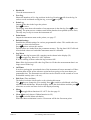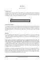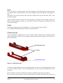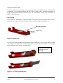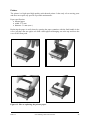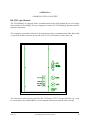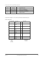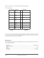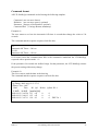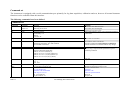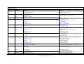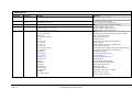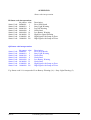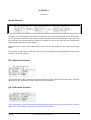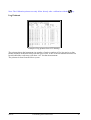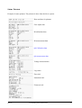
1
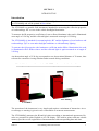
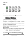
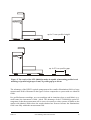
LTL2000S / SQ RETROREFLECTOMETER Manual DELTA ⋅ Venlighedsvej 4 ⋅ DK-2970 Hørsholm ⋅ Denmark ⋅ Tel. (+45) 72 19 40 00 ⋅ Fax (+45) 72 19 40 01 ⋅ www.delta.dk DISCLAIMER The information contained in this document is subject to change without notice. DELTA LIGHT & OPTICS MAKES NO WARRANTY OF ANY KIND WITH REGARD TO THIS MATERIAL, INCLUDING, BUT NOT LIMITED TO, THE IMPLIED WARRANTIES OF MERCHANTABILITY AND FITNESS FOR A PARTICULAR PURPOSE. DELTA LIGHT & OPTICS SHALL NOT BE LIABLE FOR ERRORS CONTAINED HEREIN OR FOR INCIDENTAL OR CONSEQUENTIAL DAMAGES IN CONNECTION WITH THE FURNISHING, PERFORMANCE OR USE OF THIS MATERIAL. Rev. 080104 SW ver: 1.6 DELTA LTL2000S(Q) Retroreflectometer i INDEX SECTION 1................................................................................................................................ 1 INTRODUCTION............................................................................................................................. 1 Introduction ................................................................................................................................................... 1 LTL2000S(Q) features .................................................................................................................................. 2 Getting started ............................................................................................................................................... 3 Buttons........................................................................................................................................................... 3 Measuring...................................................................................................................................................... 3 Warning and Errors ....................................................................................................................................... 3 Calibration - LTL2000S ................................................................................................................................ 6 Calibration - LTL2000SQ ............................................................................................................................. 8 SECTION 2.............................................................................................................................. 11 GENERAL INFORMATION ........................................................................................................ 11 Rl Measurement........................................................................................................................................... 11 Qd Measurement ......................................................................................................................................... 15 Instrument function ..................................................................................................................................... 17 Factory calibration....................................................................................................................................... 17 Notes on error sources ................................................................................................................................. 17 SECTION 3.............................................................................................................................. 19 KEYBOARD, DISPLAY AND FUNCTIONS.............................................................................. 19 Keyboard Layout ......................................................................................................................................... 19 Keyboard functions ..................................................................................................................................... 19 Clear log data............................................................................................................................................... 20 Measurement id ........................................................................................................................................... 20 Mean Calculation......................................................................................................................................... 21 Menu system................................................................................................................................................ 21 SECTION 4.............................................................................................................................. 25 MAINTENANCE ............................................................................................................................ 25 General care................................................................................................................................................. 25 Protection window....................................................................................................................................... 25 Battery ......................................................................................................................................................... 25 Fuses............................................................................................................................................................ 26 Lamp............................................................................................................................................................ 26 Calibration unit............................................................................................................................................ 26 Light trap ..................................................................................................................................................... 27 Printer .......................................................................................................................................................... 28 APPENDIX A .......................................................................................................................... 29 COMMUNICATION FACILITIES.............................................................................................. 29 RS-232C specification................................................................................................................................. 29 Data protocol ............................................................................................................................................... 31 Command format......................................................................................................................................... 32 Command set............................................................................................................................................... 33 APPENDIX B .......................................................................................................................... 36 Status code interpretation .............................................................................................................. 36 APPENDIX C .......................................................................................................................... 37 Print outs.......................................................................................................................................... 37 Result Printout ............................................................................................................................................. 37 Rl Calibration Printout ................................................................................................................................ 37 Qd Calibration Printout ............................................................................................................................... 37 Log Printout................................................................................................................................................. 38 Status Printout ............................................................................................................................................. 39 DELTA LTL2000S(Q) Retroreflectometer ii APPENDIX C .......................................................................................................................... 40 SPECIFICATION........................................................................................................................... 40 General Characteristics Rl ........................................................................................................................... 40 General Characteristics Qd.......................................................................................................................... 40 Electrical Characteristics ............................................................................................................................. 41 Environmental Characteristics..................................................................................................................... 41 Mechanical Characteristics.......................................................................................................................... 41 DELTA LTL2000S(Q) Retroreflectometer iii SECTION 1 INTRODUCTION Introduction This manual covers both LTL2000S and LTL2000SQ. Some functions will only be available on LTL2000SQ and will be printed in blue colour. The LTL2000S is a portable field instrument, intended for measuring the reflection properties of road markings “Rl” as seen in the vehicle headlight illumination. To measure the Rl properties (coefficient of retro reflected luminance) the road is illuminated at an angle of 1.24 deg. and the reflected light is measured at an angle of 2.29 deg. The LTL2000SQ is intended for measuring both “Rl” and the lightness of road surfaces and road markings “Qd” as seen under daylight conditions or with stationary lighting. To measure the Qd properties (the luminance coefficient under diffuse illumination) the road is illuminated with a diffuse source and the reflected light is again measured at an angle of 2.29 deg. An observation angle of 2.29 deg corresponds to an observational distance of 30 metre, thus relevant for a motorist viewing situation under normal driving conditions. Rl and Qd is important factors in the ON-SITE quality control of road markings. LTL2000SQ LTL2000S The operation of the instrument is very simple and requires a minimum of instruction. An error message or warning is given in case of unreliable or erroneous measurement. The LTL2000S(Q) measures the Rl and Qd values according to international agreements. Results are presented in plain English on a LCD display. The built-in printer and non-volatile memory provides on site registration of measurements with corresponding date and time. DELTA LTL2000S(Q) Retroreflectometer 1 Serial communication on RS232 port gives extended command, calibration, diagnostics and data dump facilities. The LTL2000S(Q) is powered by a rechargeable lead acid battery, giving several hours of measurement capacity. A mains powered battery charger is supplied as standard. LTL2000S(Q) features • Portable self-contained instrument • Measurement in full daylight • Automatic stray light compensation and error diagnostics • Dry and wet surfaces • Plane, textured & profiled markings • Measurement geometry and illumination corresponding to realistic viewing condition in traffic • Direct digital read out • Automatic mean calculation • Built-in printer • Real time clock • Automatic data storage in internal non-volatile memory • RS232 serial communication for operation, data dump, extended control and diagnostics • Automatic programmable power off function • Easy calibration procedure • Calibration unit • Carrying case DELTA LTL2000S(Q) Retroreflectometer 2 Getting started Buttons Measure Menu Enter Home Calibrate Print Sc roll down Scroll up OFF ON Measuring Turn the instrument on by pressing and holding the Retrometer LTL2000SQ v1.6 button until the LCD shows: Retrometer 2004-01-08 10:55 Calibrate the instrument if necessary, see Calibration page 6. Place the instrument on the road marking. Press the key. The measurement will start instantly. Duration approx. 3 sec. depending on measurement mode (approx. 5. sec when measuring both Rl and Qd). When finished the measured Rl (and Qd) values, the date/time or measurement id and status info is displayed. The information’s are automatically transferred to the internal data log for later readout to the serial communication port or printout. The instrument can automatically calculate and display the mean (average) value of 2 or more measurements, if the Mean Calc function is ON. See Menu system. Warning and Errors Warning and errors are indicated in the lower right positions in the second line of the display: * = Everything O.K. W = Warning Measurement O.K. but warning condition detected. L = Warning Measurement O.K. but high stray light detected. E = Error Measurement unreliable. If the error indicator is different from * then press to print–out the status from the last measurement or press one or more times to select Status Display and then use to DELTA LTL2000S(Q) Retroreflectometer 3 scroll through the status list to see the possible cause of the problem. For further description on the error messages see Status Display page 19. Alternatively or select the menu Print Status to print a complete instrument status. Note: When battery voltage becomes low a warning (W) is shown in the lower right corner of display. It is still possible to take measurements but when the voltage drops too low, readings can be erroneous. If in doubt whether the readings are correct make a control measurement on the calibration unit. Wet night measurement considerations: Making wet night measurements on warm road surfaces requires special considerations. Due to the large thermal mass of the road, the road temperature is not influenced very much by the water. Pouring water on the hot road surface will generate steam. When placing the instrument on the wet road steam will condense in the instrument also on the front window. Condense on the optical surfaces will result in measure error! Tests has shown that steam especially condensate on the outside surface of the front window. When removing the instrument from the road, the dew will evaporate quickly and the instrument will again take correct readings. It is recommended to make the "wet measurements" at the lowest possible road temperature! Print Result: Press to print the result from last calibration or measurement to the printer. Menu: Press this key to enter the menu section. Press again to scroll through the menu structure. From the Menu it is possible to control most of the instrument settings such as mean calculation, data log functions, real time setup and automatic turn off timer, see Menu system page 21. The measuring mode (Qd, Rl or both) is set using this key. The sequence of the menu functions changes depending on what mode the instrument is in at the moment. Example: when taking measurements with the mean calculation on the first function shown will be the Clear Mean function. Home: Press this key to terminate a menu or calibration and display the latest measurement result, if DELTA LTL2000S(Q) Retroreflectometer 4 the Mean calculation function is enabled and there is more than 1 measurement in the calculation then the number of measurements is shown first. Scroll Keys: In normal mode the key activates the Clear Top Log function, in menu mode it is used to scroll through the menu functions and to increment shown values. In normal mode the key activates the Edit Sequence Id function, in menu mode it is used to scroll through menu functions and to decrement shown values. For more information about the keyboard buttons please see page 19. DELTA LTL2000S(Q) Retroreflectometer 5 Calibration - LTL2000S A calibration should always be carried out before starting a new series of measurements. Calibration is done by placing the calibration unit underneath the instrument between the rails. The easiest way to place the unit is to tilt the instrument backwards. Figure 1. How to tilt the instrument. The calibration units are fitted with guidance pins on the outside. The pins mounted in the middle of the longitudinal direction of the unit shall fit in the notch in the rails. The instrument automatically compensates for zero signal, leakage and other possible error sources, and calculates the calibration factor. This process is fully automatic and if the calibration routine is followed precisely the retroreflectometer will now measure “true” Rl. Rl Calibration Rl calibration step 1 to 8 actually consists of two calibrations: a “zero calibration” and a “normal calibration”. The zero calibration is done on the calibrator light trap and the normal calibration on the ceramics. It is important to turn the Rl calibration unit the right way during the calibration sequence. See figure 2 (page 9). Press the key to enter calibration mode and follow the instructions in the display. Note: Step 1 + 4: See figure 2 on how to place the calibration unit. Step 2: The message will be shown for a couple of seconds. Step 3: The message will be shown briefly. Step 5: The message will be shown for a couple of seconds. Step 6: Edit the Rl Normal value according to the value printed on the calibration unit. Step 7: Accept the shown normal value. DELTA LTL2000S(Q) Retroreflectometer 6 The display shows: Step 1 Mount Light Trap when Ready Step 2 Step 3 Zeroing Please Wait Step 6 Rl Normal 150 = OK to Edit Wait Zero OK Zero: 0.05% Step 4 Step 5 Mount Rl Normal when ready Calibrating Please Wait Step 7 Step 8 Rl Normal 150 = when OK Calibration Done Remove Normal To verify the calibration do a Rl measurement on the normal before removing the normal in step 8. To document the calibration press the key to print. In the example above the Rl function is now calibrated to a Rl value of 150. If an error is detected during the calibration procedure then the display will indicate this. Note: DELTA • Avoid calibration in direct sunlight • Store the reference calibration unit in a dry and clean environment. LTL2000S(Q) Retroreflectometer 7 Calibration - LTL2000SQ A calibration should always be carried out before starting a new series of measurements. The LTL2000SQ is supplied with two calibration units. One for Rl and one for Qd. The order of R1 / Qd calibration is not critical. Qd calibration can be done before the Rl calibration and reverse. The Rl / Qd calibration can also be performed individually. The Qd calibration only consist of one calibration (no zero calibration is needed). Calibration is done by placing the calibration unit underneath the instrument between the rails. The easiest way to place the unit is to tilt the instrument backwards, see picture page 6. The calibration units are fitted with guidance pins on the outside. The pins mounted in the middle of the longitudinal direction of the unit shall fit in the notch in the rails, see figure 2 page 9. The instrument automatically compensates for zero signal, leakage and other possible error sources, and calculates the calibration factor. This process is fully automatic and if the calibration routine is followed precisely the retroreflectometer will now measure “true” Rl / Qd. Calibrate: Press the key to enter calibration mode. If only Rl or Qd mode is enabled then this mode is the only one shown. In the example both Qd and Rl are enabled. The display will show: Calibration = Qd = Rl Use or key to activate the wanted calibration sequence. Qd Calibration: Follow the instructions in the display. Note: Step 1: The vertical black plate on the calibration unit shall face forward (see figure 2 page 9). Step 2: The message will be shown for a couple of seconds. Step 3: Edit the Qd Normal value according to the value printed on the calibration unit. The display shows: Step 1 Step 2 Mount Qd Normal when Ready DELTA Calibrating Please Wait Step3 Step 4 Step 5 Qd Normal: 200 = OK to Edit Qd Normal: 215 = when OK Calibration Done Remove Normal LTL2000S(Q) Retroreflectometer 8 If the key is pressed the calibration result is printed. In the example above the Qd function is now calibrated to a Qd value of 215. If an error is detected during the calibration procedure then the display will indicate this. Rl Calibration: See Rl calibration page 6. Rail Guidance pin placed in notch The normal must be placed with this side up for the different calibrations. Zero calibration for the Rl calibration (step 1 in the detailed description page 5). Rl calibration (step 4 in the detailed description page 5) Qd calibration (step 1 in the detailed description page 6.) Guidance pins Figure 2. How to place the calibration normals. DELTA LTL2000S(Q) Retroreflectometer 9 Remember: DELTA Recharge battery when possible. Never leave battery discharged for longer periods of time. Keep protection window, light trap and calibration unit clean. LTL2000S(Q) is an optical precision instrument, handle with care. Store in clean and dry environment LTL2000S(Q) Retroreflectometer 10 SECTION 2 GENERAL INFORMATION Rl Measurement The Rl part of the LTL2000S(Q) Retroreflectometer measures the Rl (coefficient of retro reflected luminance) parameter. The Rl parameter represents the brightness of the road markings seen by drivers of motor vehicles by headlight illumination. The illumination angle is 1.24° and the observation angle is 2.29° simulating a drivers viewing distance of 30 metres at an eye height of 1.2 metres. The observation area is app. 45 mm. x 200 mm. The optical specification complies with EN1436. The spectral sensitivity is eye matched using SMART optical filter designed and produced by DELTA. The functional layout of the LTL2000S(Q) Rl optical system is shown in figure 3 below. A very efficient electronic stray light compensation eliminates false signals from daylight. 102 104 101 103 106 105 101 Light source 102 Receiver and spectral matching filter 103 Illumination aperture stop 104 Observation aperture stop 105 Illumination beam 106 Observation beam 107 Collimating lens 108 Mirror 109 Beam splitter 110 Road marking surface 111 Illumination field 112 Observation field 107 108 109 110 112 111 Figure 3: LTL2000S(Q) RL optical system layout DELTA LTL2000S(Q) Retroreflectometer 11 The illuminations field with a length of 200mm length and 43 mm wide gives a large measuring measurement field of 85 cm2. Combined with an observation field of 350 mm length this gives a considerable capability to measure profiled and textures makings but also a high reliability for obtaining correct readings for un even surfaces or if small debris are present at one of the instruments support pads on the marking. Because of illumination at an angle of only 1,24° to the surface in the CEN-Prescribed geometry, the illuminated patch moves ahead by 46 mm for each mm lift of the instrument (1 mm/sin 1,24° = 46 mm). A shift might affect the readings, when the tape is not completely uniform. Therefore, to avoid the shift, the instrument is moved backwards by 46 mm for each mm lift. Refer to figure 3 for results of the measurements. The RL value is roughly constant up to the height of 4 mm, but at 5 mm there is some reduction. To understand this, one needs to know that the illuminated patch moves by 46 mm per mm, but the measurement area by only 25 mm per mm at the measuring angle of 2,29° relative to the surface (1 mm/sin 2,29° = 25 mm). The measuring area is larger than the illuminated patch, and contains it, but at some lift the illuminated patch moves partly out of the measured area - causing reduction of the measured RL value. On the basis of these measurements, it can be claimed that this particular instrument has a reach of almost 5 mm down into a profiled road marking, and the corresponding 5×46 mm = 23 cm reach along gaps. This reach is assumed to be 20 cm to be on the safe side. The significance is that the instrument can readily be used to measure the RL of profiled road markings, when the profiles are at most 5 mm high, or gaps between profiles are at most 20 cm. Refer to figure 5 page 14. In practice, it is necessary to take readings at a number of positions covering one or more profiles. There may be variation with the position, but the average value will reflect the true RL value of the profiled road marking as experienced by a driver at night. Most of profiled road markings used on roads in Europe can be measured with the LTL 2000S(Q), and are in fact measured with the LTL2000 as a matter of routine. Examples are 'Spotflex', Longflex', 'Rainline' and 'Drop-on line'. FOR MARKINGS EXCEEDING 5 MM HEIGHT/200 MM IN SPACING PLEASE CONTACT DELTA. DELTA LTL2000S(Q) Retroreflectometer 12 R L of a road marking 500 be am s 400 se pa rat ing 300 200 100 0 0 1 2 3 4 5 H (mm) H Figure 4: Simulation of profiled markings and/or un-even markings: Lift of a retroreflectometer to a height H and the resulting RL values. DELTA LTL2000S(Q) Retroreflectometer 13 up to 5 mm profile height up to 20 cm profile gap Figure 5: The reach of the LTL 2000S(Q) makes it capable of measuring profiled road markings of profile height up to 5 mm, or profile gap up to 20 cm. The advantage of the DELTA optical arrangement with a smaller illumination field in a large measurement field is illustrated in the figure 6 below compared to a system with two identical fields. Pro profiled/textures markings, on even markings and in situations where a small debris (e.g. small stone) the instrument is lifted / tilted. The advantage of the LTL2000S(Q) optical arrangement is that the measurement still is correct in contrary to other systems available on the market with identical fields where the results obtained are incorrect because the illuminations field is not fully within the measurement field. DELTA LTL2000S(Q) Retroreflectometer 14 Before tilt /shift of high position LTL2000 5 mm profile capability. Competitor < 0.5 mm profile capabilty After tilt/shift of high position LTL2000 5 mm profile capability. Competitor < 0.5 mm profile capabilty Area not measured Figure 6: The LTL2000S(Q) illuminations/measurement fields ( 5mm profile capability) compared to a system with identical fields (< 0.5 mm profile capability) clearly shows the advantage of the LTL2000S(Q) for obtaining reliable and reproducible measurements on real markings. Qd Measurement The Qd part of the LTL2000SQ Retroreflectometer measures the Qd (coefficient of diffuse reflected luminance) parameter. The Qd parameter represents the Lightness of road surfaces and road markings seen by drivers of motor vehicles under daylight conditions or with stationary lighting. The Qd measurement function of the LTL2000SQ complies with the EN1436 for normal nonglossy road markings with a maximum profile. For measurement on glossy road markings or markings with a profile height exceeding 2 mm please contact DELTA. The illumination system recommended in EN1436 for obtaining the diffuse illumination for measuring of Qd is an integrating sphere but it is also stated that other illuminations systems can be used if similar results are obtained. The very compact illumination systems in LTL2000SQ is a result of a considerable research effort at DELTA using advanced optical simulation programs. The patent pending illumination system is shown in figure 7. The results obtained with this illumination system is in close agreement with results obtained on Qd measurements using an integrating sphere systems as Qd30 for normal non-glossy road markings with a profile height up to 2 mm. For further information regarding this matter please contact DELTA. DELTA LTL2000S(Q) Retroreflectometer 15 515 516 517 518 512 512 Road marking surface – – Light source Diffusing box with white interior finish Thin perforated plate Aperture into diffusing box 517 518 Figure 7. Qd illumination system DELTA LTL2000S(Q) Retroreflectometer 16 Instrument function Physically the instrument is dominated by the “control tower”. The tower contains the Rl illuminating and observation system and the control electronics. The unit on top of the base structure contains the Qd illumination system, the observation system is the same for both Rl and Qd. The base structure contains an optical system with mirrors that directs Rl illumination beam towards the road surface and the Rl or Qd signal to the detector through a dust-protection window. The measuring area is shielded by an aluminium housing. The instrument is controlled by a microprocessor that executes the measurement automatically by the push of a button and presents the result on a display. The result is automatically transferred to an internal non-volatile memory. The result and corresponding measurement id, time and date can be printed by the built-in printer. The LTL2000S(Q) is operated with a small keyboard located at the top of the Retroreflectometer. Further, Retroreflectometer control is possible over a serial communication link (RS232). Stored data can easily be transferred to a host PC for further processing. The LTL2000S(Q) is powered by a built-in lead acid battery, which under normal operation will keep the Retroreflectometer operating a normal working day. The battery is recharged by use of an external charger. Factory calibration The LTL2000S(Q) Retroreflectometer is factory calibrated. This calibration is carried out by using calibration units mounted in specially designed frames. The calibration unit's values are measured in the laboratory using traceable methods and equipment. Notes on error sources Stray light can enter the instrument between the skirts and the road. Leakage will under normal measurement conditions not be significant. Nevertheless it may occur. Before each measurement the LTL2000S(Q) automatically evaluates the leakage and the result is compensated before read out. In case of a significant leakage level a warning or error message is given and special precautions such as screening may be necessary. Instrument leak, drift and offset errors are compensated by means of data obtained during the calibration procedure. It is very important to keep the light trap, the dust-protection window and the ceramics on the calibration unit clean. Especially the light trap is critical. The LTL2000S(Q) illumination angle is 1.24° relative to the road surface. Because of this small angle accurate placement on the road is important. Avoid pebbles and abnormal irregularities. The LTL2000S(Q) must be parallel with and close to the road. The LTL2000S(Q) Retroreflectometer is a rugged instrument, but it is an optical instrument and must be handled as such. DELTA LTL2000S(Q) Retroreflectometer 17 The LTL2000S(Q) is factory calibrated. Nevertheless start important measurements with a calibration. Study the Retroreflectometer status and error messages if any. See also Section 4 – Maintenance (page 25). When the battery voltage becomes low a warning is shown in the display (W). It is still possible to take measurements but when the voltage drops further, readings can be erroneous. If in doubt whether the readings are correct make a control measurement on the calibration unit. Note Keep light trap, optical-protection window and ceramics on calibration unit clean. Keep battery fully charged. A well charged battery is more resistant to ageing and damage by freezing DELTA LTL2000S(Q) Retroreflectometer 18 SECTION 3 KEYBOARD, DISPLAY AND FUNCTIONS Keyboard Layout . . . . . . Figure 8. Keyboard. Keyboard functions Key Label Key Function Turns the instrument On. Hold activated until the sign on message appears in the Display. Turns the instrument Off. Terminates all activity and powers off. Take a measurement and show the result in the display. All relevant data is automatically stored in the data log for later print or dump to the communication port. Enter calibration menu. Follow the instructions in the display. DELTA LTL2000S(Q) Retroreflectometer 19 Enter - Activates selected function, accepts changed settings and confirms choices. Home (Home position) - Cancels selected function or menu and return to top control level displaying the latest measurement result. Outputs the latest measurement or calibration result to the printer. Printout has to finish completely before any other function can be selected. Printout can only be terminated by turning off the instrument with Menu - When in normal operation mode this key activates the menu system and displays the first item in the menu stack. When already in menu mode it selects the next menu item, it is possible to leave the menu mode entirely at any time with the function keys. key or by selecting other Scroll up - In normal mode the key activates the Clear Top Log function. See Clear log data below. In Menu mode it functions as a scroll or increment function. Values are incremented until they reach their predefined max. limit and then automatically change to their predefined min. limit. The key is auto repeating with increasing repetition rate when held active. Scroll down - In normal mode the key activates the Edit Measurement Id (Seq Id) function. See Measurement id below. In menu mode it functions as a scroll or decrement function. Values are decremented until they reach their predefined min. limit and then automatically change to their predefined max. limit. The key is auto repeating with increasing repetition rate when held active. Clear log data Data log entries can be deleted. Pressing in normal mode activates the deletion of the measurement from the top of the data log. The values from the previous measurement will be shown and if a Measurement id was defined for that measurement it will be restored as well. All log data can be deleted using Menu function Free log. See page 24. Clearing the top log will reset the mean calculation. Measurement id LTL2000S(Q) has a built in function to mark each measurement with a user defined name (sequence id) and a unique sequence number automatic generated by the instrument. The sequence id and the sequence number will also be stored in the log. The length of the sequence id text is 6 characters. If any sequence id is defined, the id text and a sequence number are shown in the display. DELTA LTL2000S(Q) Retroreflectometer 20 Entering Measurement id: To enter / edit the sequence id press the button when in home position. Use the button to scroll through the alphabet in direction A..Z (starting with the space character), 0..9. The button will scroll through the alphabet in opposite direction. When the wanted character is shown press the button to advance to the next position. You have to step through all 6 positions before the sequence id function will be accepted. When typing a new sequence id text or editing an old one, the sequence number is reset to 0. When all 6 positions are set to space the sequence id function is undefined and no longer included in the log nor shown in the display. This can also be done using the Menu command: Disable Id Mean Calculation The instrument automatically calculates and displays the mean (average) value of 2 or more measurements when the Mean Calc function is ON. See Menu system. If the Rl / Qd value shown in the display contains a decimal point (.) then the shown value is a mean value. The number of samples is displayed for one second after each measurement. Press to redisplay this information. The following actions will clear the mean calculation: • Clear Top Log function • Toggling the Rl / Qd modes • Clear mean (from menu) • New calibration Measurements stored in the log are not the displayed average values but the actual measurement value. If a measurement error occurs (e.g. Rl / Qd out of limit) a message: “Error! Can’t calc new mean!” is shown in the display. Both measurements (Rl / Qd) are ignored, a new average is not calculated and the sample number is not incremented. The measurements how ever are stored in the log as normal. Menu system Press to enter the menu system. Menu points are: • Qd Mode Press to toggle Qd mode ON and OFF. When ON the instrument will perform a Qd measurement when is pressed. • Rl Mode Press to toggle Rl mode ON and OFF. When ON the instrument will perform a Rl measurement when is pressed. • Status Display The results and status recorded during measurement and calibration can be shown in DELTA LTL2000S(Q) Retroreflectometer 21 the display one at a time using the keys. An * after a text means that the message only is shown at special occasions e.g. an error or warning! LTL2000S(Q) Display Explanation (The following messages are possible) R: 146 Q: 64 The latest measurement results. Rl Signal: 143 The measured Rl “raw signal” level. Rl Out of Limit* The Rl value is negative. Rl Sig Overflow* Warning: unreliable measurement! If the measured signal is greater than a predefined limit then a warning will be displayed for one second before the Rl Sig value is shown. Error sources: Rl marking exceeds the dynamic range of the instrument, failure in the optical system e.g. dew or dirt on the front window or it can be an electrical failure. Rl Stray L: 0 The measured stray light representing the amount of light getting into the instrument from outside. Stray light levels under acceptable predefined limits is displayed as 0. Rl High Stray L* Warning. A high stray light signal can indicate problems with direct sunlight from a low sun on a very rough or uneven surface. Special precautions must, if necessary, be taken to hinder the light from shining directly on the measurement area. A warning will be displayed for one second, if the signal gets critical, before the Rl Stray L value. VBat Rl: 11.2V The battery Rl voltage measured while the lamp is on. The reading can be used to check the charge condition of the built-in 12 V battery. A warning will be displayed for one second before the VBat Rl voltage is shown, if the voltage under load drops to a critical low value. If the battery voltage gets very low, the instrument will shut off during the measurement because the battery voltage drops further when the lamp is lit. This condition will be reported in the display on the next power on. Measuring will not be possible until the battery is recharged. Low VBat Warning* Qd Signal: 875 DELTA The measured Qd signal level. LTL2000S(Q) Retroreflectometer 22 LTL2000S(Q) Display Explanation (The following messages are possible) Qd Out of Limit* The Qd value exceeds the theoretical value of 318. Qd Sig Overflow* See Rl Sig Overflow. Qd Stray L: 0 The measured Qd stray light level. Qd High Stray L* See Rl High Stray L. VBat Qd: 11.3V See VBat Rl. Low VBat Warning* VBat idle: 12.6V Low VBat Warning* DELTA The battery idle voltage is measured just before the lamp was turned on. The reading can be used to check the charge condition of the built-in 12 V Battery. A warning is given in the display if the voltage drops below its predefined minimum limit. The warning will be displayed for one second before the VBat idle voltage is shown. VBat Now: 12.8V The actual battery voltage just before entering the VBat Now menu. Can be used to check the charger. When a charger is connected the voltage should after a period of time be > 13.5 V. Free Log: 744 The amount of free log entries. Log Full* A warning is given if the data log has run full. This means that no new measurements can go into the log. The log will have to be cleared before this warning is removed. LTL2000SQ v. 1.6 (c)08-JAN-04 S/N: 704 The instrument type and software version. The firmware creation date. The instrument serial number. LTL2000S(Q) Retroreflectometer 23 • Disable Id Clear the measurement id. • Free Log Shows the numbers of free log positions in the log. Pressing will clear the log. In order to avoid accidental erasing the log, a second is required. • Print Log Output all the data in the log to the printer. Press to select. The display now shows the number of measurements in the data log. Press to start printing. The print process continues until all the data has been printed (newest first). The only way to stop is to turn the instrument off. • Print Status Output the instrument status to the printer, see page 37. • Default Settings Establish the default settings for various programmable values. This enables the user to start over from a default state. Press again to activate this action. Default values are loaded from the permanent memory. The log data is NOT effected. After default values are loaded the instrument must be calibrated. • Log Warn When the data log becomes full a warning can be shown in the display (W). Use to toggle Log Warn ON / OFF function. If off no warning is shown when the log becomes full! Note: If the log becomes full when Log Warn is ON then the measurement data is no longer stored in the log! • Off Timer In order to prolong the operational time of the instrument it has an automatic off function that shuts off the power when no action has been going on for more than a programmable time. The automatic turn off time can be from 60 to 600 seconds or it can be disabled entirely (time < 60 sec.). • Edit Year (Time and date) The built-in real time clock can be set by selecting this menu. keys to change the Year setting. Press to switch to edit Month, edit Date, Use edit Hour and edit Minute. When the display shows the desired date and time press a last time to set the real time clock to the displayed setting • Mean Use to toggle Mean function ON / OFF. See also page 21. • Clear Mean (only shown if Mean function is ON) Press to reset the Mean calculation. When the Mean calculation is active Clear mean will be the first menu point. DELTA LTL2000S(Q) Retroreflectometer 24 SECTION 4 MAINTENANCE General care The Retroreflectometer is constructed for outdoor use in ordinary good weather conditions. It will stand moist weather with wet roads, but caution must be taken against rain or splashes and dirt from traffic. The LTL2000S(Q) Retroreflectometer is an optical instrument and shall be handled as such. Avoid shock and vibration if possible. Note Keep dust/protection window and light trap clean Protection window The protection window is located in the optical unit. The protection window is coated with a high efficiency anti reflection coating. Care must be taken not to damage this coating by cleaning. A fine brush can be used for removing loose particles/dust. If this is not sufficient the window should by cleaned using a soft paper tissue or cloth and some window cleaning liquid. Battery The LTL2000S(Q) Retroreflectometer is powered by a sealed 12V/3.5Ah lead acid battery, which under normal use requires no maintenance. However it is recommended to keep the battery fully charged. A fully charged battery is more capable of withstanding low temperature and ageing. Battery charger is provided as a standard accessory for charging the battery from mains. The output cable of the charger is equipped with a socket matching the connector in the instrument. Connect charger to mains and instrument. The red indicator will be switched on as long as the charging is in progress. Thereafter it switches periodically on and off. Normally the charging will take about 8 hours. Typically the battery achieves 90% of the capacity in 5 hours. No harm will result from leaving the charger connected for time in excess of the above indicated duration of the charging process. However, the battery must be disconnected from the charger when disconnecting the mains. The battery is located in a compartment at the front of the tower. To replace the battery remove the screws holding the right side cover plate, seen from behind. Remove the screws from the right hand side of the red front- and back cover plate. Remove the side cover plate. Remove the 2 nuts holding the clamp plate. Lift out the battery of its container. The battery can now be removed and replaced. Refit in reverse order. DELTA LTL2000S(Q) Retroreflectometer 25 Fuses Fuses, two pieces, are placed at the rear of the instrument. The charging fuse protects the battery against short circuit and other errors in the charging connector, charger or charging system. The battery fuse protects battery and electronics against short circuit and other errors in the electronic system. Always replace a blown fuse with one of equal rating. To change a fuse carefully unscrew the plastic cap fuse holder by using e.g. a coin. Pull out the fuse from the cap and insert the new one and reassemble Lamp The halogen lamps requires no maintenance. At life end they must be replaced. It is recommended that replacing is done by trained personal. Calibration unit The road marking is simulated by a piece of white ceramics mounted on a aluminium block with a small grip. Ceramics has very stable optical properties and cleaning is easy because of the smooth surface. Rl calibration unit Ceramics Qd calibration unit Figure 9. Calibration units To make sure that calibration of the retroreflectometer is correct it is important that the ceramics on the calibration unit is clean and undamaged. All ways keep the calibration unit well protected. If the ceramics is stained, scratched or broken the calibration unit has to be replaced. In case of dust on the ceramics surface, clean gently with a damp soft cloth if necessary use a DELTA LTL2000S(Q) Retroreflectometer 26 mild household detergent. To ensure reliable measurements, it is recommended that the calibration unit is periodically recalibrated to a traceable standard. DELTA Light & Optics offers calibration traceable to PTB (Physikalsich-Technishe Bundesanstalt). For information contact your distributor or DELTA Light & Optics. Light trap Zero signals are simulated by a light trap made of two glossy and black plastic sheets mounted in an acute angle. If clean this will provide very efficient light absorbing device. Rl calibration unit Light trap Figure 10. Light trap It is necessary to disassemble the light trap to clean it efficiently. This is easily done by lifting and pulling it. Cleaning can be done by using a fine brush, clean pressurised air or a soft paper tissue/cloth and some window cleaning liquid. Pull and lift the upper lighttrap-plate for cleaning. Figure 11. Cleaning lighttrap-plate. DELTA LTL2000S(Q) Retroreflectometer 27 Printer The printer is a high speed high quality mini thermal printer. It has only a few moving parts and does not require any special or periodic maintenance. Paper specification: • thermal paper • width: 57.5 mm • diameter: 31 mm (max.) Replacing the paper is easily done by opening the paper container with the little handle in the cover, just place the new paper role with a short paper tail hanging out at the top and close the cover with a firm push. Figure 12. How to replacing the printer paper. DELTA LTL2000S(Q) Retroreflectometer 28 APPENDIX A COMMUNICATION FACILITIES RS-232C specification The LTL2000S(Q) is equipped with a communication facility that enables the use of a simple data terminal or an ordinary PC type computer for control of LTL2000S(Q) functions and for log data acquisition. The computer or terminal connects to the Instrument using a communication cable fitted with a 9 pin male D-Sub connector at one end and a 9 or 25 pin connector at the other end. The electrical connections meet the EIA/TIA-232E and CCITT V.28 specifications. e.g. it can be connected to any standard RS232 serial communications port with the below wiring. DELTA LTL2000S(Q) Retroreflectometer 29 Connections in the 9 pin D-Sub connector. pin # Function Signal Direction 3 Receive Data Data to LTL2000S(Q) 2 Transmit Data Data from LTL2000S(Q) 5 Signal Ground Signal Ground Connection example #1. PC with 25-pin D-Sub communication port. Cable connections: PC Port DTE LTL DTE 1 FG X 2 TxD -- 3 3 RxD -- 2 4 RTS X 5 CTS X 6 DSR X 7 SG -- 8 DCD X 20 DTR X 25-pin female D-SUB DELTA pin name 5 9-pin male D-SUB LTL2000S(Q) Retroreflectometer 30 Connection example #2. PC with 9 pin D-Sub communication port. Cable connections: PC Port DTE pin name LTL DTE 1 CD X 2 RxD -- 2 3 TxD -- 3 4 DTR X 5 SG -- 6 DSR X 7 RTS X 8 CTS X 9 RI X 9-pin female D-SUB 5 9-pin male D-SUB As it can be seen, the interconnections have been held to an absolute minimum, and in some rare situations there will have to be established additional connections on the PC side. Please refer to your PC manual for further information. Data protocol The communication between the LTL2000S(Q) and the computer equipment takes place using the following settings: Baud Rate ............................................................................................................9600 bit/sec. Number of data bit................................................................................................................ 8 Parity................................................................................................................................ none Stop bit .................................................................................................................................. 1 Hand Shake ............................................................................................................ XOn/XOff DELTA LTL2000S(Q) Retroreflectometer 31 Command format All LTL2000S(Q) commands are built using the following template. Command (one ore more letters) Delimiter (one ore more spaces, optional) Parameter (Integer or Real number, optional) Command End (Carriage Return, mandatory) Example #1: The user wants to see how the Automatic Off timer is set and then change the value to 120 seconds. The command and the response sequence look like this. Ot Automatic Off Timer = 300 sec. Ot 120 Automatic Off Timer = 120 sec If for some reason the communication fails or the command is undefined the LTL2000S(Q) responds with a question mark. <?> If the parameter lies outside the defined range for that parameter, the LTL2000S(Q) returns the present setting without any change. Example #2: The user wants to read the data in the data log The command and the response sequence can look like this. LR Log Dump: 2002 Aug 12 13:27:13 3 Entrys: Free: 1495 Date Time Rl Qd R-Stat Q-Stat ID # Y-M-D H:M:S [mcd/m²)/lx] 2002-08-12 12:45:56 123 off 0 0 2002-08-12 12:46:13 125 off 0 0 2002-08-12 13:47:11 120 82 0 0 DELTA 1 * DELTA LTL2000S(Q) Retroreflectometer 32 Command set The instrument is equipped with a serial communication port primarily for log data acquisition, calibration and test, however all normal instrument functions can be controlled from this interface. The following commands have been defined Command set Command DAn Parameter Response Meaning None 2002 8 12 2002 Aug 10 09:45:47 2002 Aug 12 09:55:33 Real time clock Date and time New Date (time unchanged) DPS FV None None Elaborated instrument status Instrument firmware version, serial and other instrument information ID None See Status PrintOut for details Retroreflectometer LTL2000SQ v1.0 DELTA (c)02-JUL-24 #848SQ II None Y N Initialise Instrument settings [Y/N] Initialising Instrument. Zero and Calibrate II Command Terminated Set Default values from ROM Execute initialisation, Instrument not calibrated! Cancel initialisation command without any change LC LE None None Data log clear message Data in Log is output comma separated for input to standard spreadsheet LS None LWT LWF M none Data log empty Instrument s/n: n Date/Time,Rl,Qd,RS,QS,ID,ID# 2002-08-12 12:35:56,off,24,0,0,, 2002-08-12 12:36:13,79,off,0,0,DELTA,1 2002-08-12 13:27:11,76,22,0,0,DELTA,2 2002-08-12 13:27:44,76,22,0,0,TEST,1 * Log Status Log: 3 Free: 1297 Log Full Warning Display On Log Full Warning Display Off * Qd: 123 (mcd/mý)/lx Qd Status Code: 0 00000000 2002 Aug 12 13:53:16 Rl: 33 (mcd/mý)/lx Seq ID : DELTA #3 DELTA None Instrument serial number LTL2000S(Q) Retroreflectometer Log end Log statistics Enable the Log Full warning in LCD Disable the Log Full warning in LCD Perform a measurement. Qd result Qd status code Time for Qd measurement Rl result Sequence Id 33 Command set Command Parameter OTn None 59 180 None None 123 PV QCn QEn RCn REn Response Rl Status Code 0 00000000 2002 Aug 12 13:53:19 LTL2000SQ v1.0 s/n:n Off Timer = 300 sec. Off Func: Off Off Timer: = 180 sec. V_PMT = 644 Volt QdF: 0.1366 Cal Qd? [Y/N] Cal Qd! Qd Factor = 0.7564 Qd Normal = 123 Qd On Qd Off Qd On RlF: 2.038 Cal Rl [Y/N] Cal Rl Rl Factor = 2.032 Rl Normal = 123 Rl On Rl Off Rl On Zero Adjust? [Y/N] Zero Rl *** Zero Reading *** Lamp On: 12 Lamp Off: 10 New Rl_Sy_Leak: 2 Rl Status Code 0 00000000 Qd Status Code: 0 00000000 Seq ID: DELTA Meas in Seq: 3 Voltage on PMT Query Qd calc factor Calibrate Qd to 123 Y/N response to start Calibrating Qd Calculated calc factor New active Qd normal Query Qd function Set Qd function Off Set Qd function On Query Rl Calc factor Calibrate Rl to 123 Y/N response to start Calibrating Rl Calculated calc factor New active Rl normal Querry Rl function Set Rl function Off Set Rl function On Perform Rl zero adjust with Y/N confirmation Measuring zero signal Result from zero reading Signal with lamp on Signal with lamp off New SyLeak signal Status code and bit pattern if status not zero then the status code is decoded Querry Sequence number Measurements with this ID TEST2 Seq ID: TEST2 Meas in Seq: 0 Change ID to TEST2 No measurements with this ID None 10 02 25 2002 Aug 12 13:59:37 2002 Aug 12 10:02:25 Real time clock Date and Time New Time (Date unchanged) None F T None 123 RZ None F T None SD None SNn None TIn DELTA Meaning Rl status code Time for Rl measurement Instrument Id Automatic turn off time when not in use. Range 60 to 600 sec. Disable for time < 60 sec LTL2000S(Q) Retroreflectometer 34 Command set Command TO Parameter None Response Sensor Off Meaning Turn sensor off (power off) VAn VB VS None 11.50 None None VBat Alarm: 11.00 Volt VBat Alarm: 11.50 Volt VBat = 12.77 Volt VBat Lamp Off: 12.78 Volt VBat Rl Lamp On : 11.99 Volt VBat Qd Lamp On : 12.09 Volt Set point for low bat warning New set point for low bat warning Measure actual voltage on lead-acid battery Measured VBat with min. load Measured VBat with Rl. lamp load Measured VBat with Qd lamp load <?> None DA [yyyy mm dd] DPS x-stat FV Firmware Version ID ID II Init [Y/N] LC Log Clr LE Log , sep LS Log stat LWn Log warn [T/F] OT Off timer PV PMTV QEn Qd[T/F] QCn Cal to n REn Rl [T/F] RCn Calc to n RZ zero M Measure SNn Seq # TI [hh:mm:ss] TO Turn Off VA Bat alarm VB VBat VS V-idle V-lamp Help menu. Query/Set Real Time Watch Date year/month/date Query instrument status Query Firm Ware info Instrument S/N Enable/Execute Instrument Initialisation Clear Log Data Send Log Data in comma seperated form Query Data Log Status Enable/Disable the Display of Log full warning [T/F] Query/Set the Automatic Turn Off Timer Read PMT Voltage Enable/Disable Qd function Calibrate Qd to n Enable/disable Rl Function Calibrate Rl to n Zero adjust Rl measurement Execute enabled measurements Query/Set Sequence ID Query/Set Time Turn instrument Off Query/Set Alarm for Low VBAT Query Battery voltage Query Voltage conditions DELTA LTL2000S(Q) Retroreflectometer 35 APPENDIX B Status code interpretation Rl Status code interpretation: bit pattern value Status Code: 00000001 1 Status Code: 00000010 2 Status Code: 00000100 4 Status Code: 00001000 8 Status Code: 00010000 16 Status Code: 00100000 32 Status Code: 01000000 64 Status Code: 10000000 128 Description Error in Rl Result Stray Light Warning Log full Warning Not defined Low Battery Warning High Zero signal Warning High Signal with Lamp on Error High Signal with Lamp off Error Qd Status code interpretation: Status Code: Status Code: Status Code: Status Code: Status Code: Status Code: Status Code: Status Code: bit pattern 00000001 00000010 00000100 00001000 00010000 00100000 01000000 10000000 value 1 2 4 8 16 32 64 128 Description Error in Qd Result Stray Light Warning Not defined Not defined Low Battery Warning Not defined High Signal with Lamp on Error High Signal with Lamp off Error E.g. Status code 18 is composed of Low Battery Warning (16) + Stray Light Warning (2) DELTA LTL2000S(Q) Retroreflectometer 36 APPENDIX C Print outs Result Printout Examples of result printouts showing the measured values, the Measurement Id and the number of measurements with this id, the number of measurements used to calculate the mean value, the date and time the measurement was taken, the number of data in the data log, the measurement status and the instrument serial number. Note that one or more of the shown data can be left out depending on the selected operation mode. If the status is other than 0 then there was a special condition detected during the measurement and this will also be printed. Rl Calibration Printout The printout after a Rl Calibration measurement showing the selected Rl Normal value. The date and time for the calibration and the status for the measurement. Qd Calibration Printout The printout after a Qd Calibration measurement showing the selected Qd Normal value, the date and time for the calibration and the status for the measurement. DELTA LTL2000S(Q) Retroreflectometer 37 Note: The Calibration printout can only follow directly after a calibration with the key. Log Printout Example of log printout from LTL2000SQ The printout shows the instrument s/n, number of entries, number of free log entries, a data header and then all the data listed with the newest first, if one of the measurement modes has been disabled the result entry will show “off” for that measurement. The printout is done from the Menu system. DELTA LTL2000S(Q) Retroreflectometer 38 Status Printout Example of status printout. The printout is done from the Menu system. Date and time for printout Zero adjust data Rl calibration data Rl measurement data Qd Calibration data Qd measurement data Voltage measurements Log status Error info Instrument info Firmware info DELTA LTL2000S(Q) Retroreflectometer 39 APPENDIX C SPECIFICATION General Characteristics Rl Illumination angle to the road ......................................................................................... 1.24º Observation angle to the road.......................................................................................... 2.29º Equivalent observer distance............................................................................................30 m Observation angular spread .......................................................................................... ±0.17º Type 30m CEN Illumination angular spread horizontal ........................................................................ 0.33º Illumination angular spread vertical ............................................................................ 0.17º Field of measurement: Width ........................................................................................................................ 45 mm Length (typ.) ........................................................................................................... 200 mm Min. reading (mcd·m-2·lx-1) ....................................................................................................0 Max. reading (mcd·m-2·lx-1) .................................................................................... Typ. 2000 Profile height up to .................................................................... 4 mm (or 20 cm profile gap) General Characteristics Qd Illumination .................................................................................................................Diffuse Observation angle to the road.......................................................................................... 2.29º Equivalent observer distance............................................................................................30 m Aperture angle ................................................................................................................. 0.33º Field of measurement: Width ........................................................................................................................ 45 mm Length (typ.) ........................................................................................................... 200 mm Min. reading (mcd·m-2·lx-1) ....................................................................................................0 Max. reading (mcd·m-2·lx-1) .............................................................................................. 318 DELTA LTL2000S(Q) Retroreflectometer 40 Electrical Characteristics EMC ..................................................................................................................... EN 50081-1 EN 50082-1 Power supply: Battery.................................................................... Build in 12 volt 3.5Ah sealed lead acid External charger............................................................................... 100-240 V~/ 50-60 Hz Charging time ..............................................................................................approx. 8 hours 90% capacity after approx. 5 hours Charger fuse (5*20 mm) .......................................................................................... T3.15A Power supply fuse (5*20 mm) ................................................................................. T3.15A Data memory ........................................................................................ >1000 measurements Data retention (from purchase) ............................................................................Typ. 5 years Serial communication mode...................................................................................9600,N,8,1 Data flow control...................................................................................................... Xon/Xoff Interface....................................................................................................................... RS 232 Environmental Characteristics Temperature: Operating ....................................................................................................... 0ºC to + 45ºC Storage*) ...................................................................................................... -15ºC to + 55ºC Humidity........................................................................................................ Non condensing *) Battery must be fully charged Mechanical Characteristics Max. length................................................................................................................. 570 mm Max. width ................................................................................................................. 200 mm Max. height................................................................................................................. 465 mm Weight ................................................................................................................approx. 11 kg Shipping Weight.................................................................................................approx. 30 kg Construction: Housing ............................................................................................................. Aluminium Keyboard................................................................................................... Plastic laminated Circuit boards.................................................................................................... Epoxy glass Printer: Thermal paper ....................................................................... width / dia. 57.5 mm / 31 mm DELTA LTL2000S(Q) Retroreflectometer 41