1
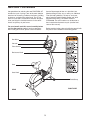
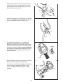
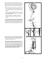
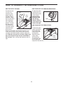
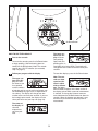
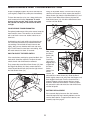
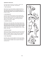
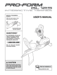
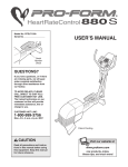
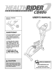
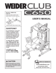
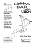
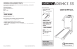
Patent Pending
Model No. PFEX20040
Serial No.
USER'S MANUAL
Serial
Number
Decal
QUESTIONS?
If you have questions, or if there
are missing or damaged parts,
we will guarantee complete satisfaction through direct assistance from our factory.
TO AVOID DELAYS, PLEASE
CALL DIRECT TO OUR TOLLFREE CUSTOMER HOT LINE. The
trained technicians on our customer hot line will provide immediate assistance, free of charge
to you.
CUSTOMER HOT LINE:
1-888-533-1333
Mon.–Fri., 6 a.m.–6 p.m. MST
CAUTION
Read all precautions and instructions in this manual before using
this equipment. Keep this manual
for future reference.
Visit our website at
www.proform.com
new products, prizes,
fitness tips, and much more!
TABLE OF CONTENTS
IMPORTANT PRECAUTIONS . . . . . . . . . . . . . . . . . . . . . . . . . . . . . . . . . . . . . . . . . . . . . . . . . . . . . . . . . . . . . . . .2
BEFORE YOU BEGIN . . . . . . . . . . . . . . . . . . . . . . . . . . . . . . . . . . . . . . . . . . . . . . . . . . . . . . . . . . . . . . . . . . . . . .3
ASSEMBLY . . . . . . . . . . . . . . . . . . . . . . . . . . . . . . . . . . . . . . . . . . . . . . . . . . . . . . . . . . . . . . . . . . . . . . . . . . . . . . .4
HOW TO OPERATE THE EXERCISE CYCLE . . . . . . . . . . . . . . . . . . . . . . . . . . . . . . . . . . . . . . . . . . . . . . . . . . . .8
MAINTENANCE AND TROUBLESHOOTING . . . . . . . . . . . . . . . . . . . . . . . . . . . . . . . . . . . . . . . . . . . . . . . . . . . .11
CONDITIONING GUIDELINES . . . . . . . . . . . . . . . . . . . . . . . . . . . . . . . . . . . . . . . . . . . . . . . . . . . . . . . . . . . . . . .12
PART LIST . . . . . . . . . . . . . . . . . . . . . . . . . . . . . . . . . . . . . . . . . . . . . . . . . . . . . . . . . . . . . . . . . . . . . . . . . . . . . .14
EXPLODED DRAWING . . . . . . . . . . . . . . . . . . . . . . . . . . . . . . . . . . . . . . . . . . . . . . . . . . . . . . . . . . . . . . . . . . . .15
HOW TO ORDER REPLACEMENT PARTS . . . . . . . . . . . . . . . . . . . . . . . . . . . . . . . . . . . . . . . . . . . . .Back Cover
LIMITED WARRANTY . . . . . . . . . . . . . . . . . . . . . . . . . . . . . . . . . . . . . . . . . . . . . . . . . . . . . . . . . . . . . .Back Cover
IMPORTANT PRECAUTIONS
WARNING:
To reduce the risk of serious injury, read the following important precautions before using the exercise cycle.
1. Read all instructions in this manual before
using the exercise cycle.
8. Always keep your back straight when using
the exercise cycle; do not arch your back.
9. If you feel pain or dizziness while exercising,
stop immediately and cool down.
2. It is the responsibility of the owner to ensure
that all users of the exercise cycle are adequately informed of all precautions. Use the
exercise cycle only as described in this manual.
10. The exercise cycle does not have a free wheel;
the pedals will continue to move until the flywheel stops.
3. Use the exercise cycle indoors on a level surface. Keep the exercise cycle away from
moisture and dust. Place a mat under the
exercise cycle to protect the floor.
11. The pulse sensor is not a medical device.
Various factors, including the user's movement, may affect the accuracy of heart rate
readings. The pulse sensor is intended only
as an exercise aid in determining heart rate
trends in general.
4. Inspect and properly tighten all parts regularly. Replace any worn parts immediately.
5. Keep children under the age of 12 and pets
away from the exercise cycle at all times.
12. The exercise cycle is intended for home use
only. Do not use the exercise cycle in
a commercial, rental, or institutional setting.
6. Wear appropriate clothes when exercising; do
not wear loose clothes that could become
caught on the exercise cycle. Always wear
athletic shoes for foot protection.
13. A warning decal has been placed on the exercise cycle in the location shown on page 3. If
the decal is missing, or if it is not legible, call
our Customer Service Department toll-free at
1-888-533-1333 and order a free replacement
decal. Apply the decal in the location shown.
7. The exercise cycle should not be used by
persons weighing more than 250 pounds.
WARNING:
Before beginning this or any exercise program, consult your physician. This
is especially important for persons over the age of 35 or persons with pre-existing health problems.
Read all instructions before using. ICON assumes no responsibility for personal injury or property
damage sustained by or through the use of this product.
2
BEFORE YOU BEGIN
Congratulations for selecting the new PROFORM® GT
30 exercise cycle. Cycling is one of the most effective
exercises for increasing cardiovascular fitness, building
endurance, and toning the entire body. The GT 30
exercise cycle offers a selection of features designed
to let you enjoy this healthful exercise in the convenience and privacy of your home.
Service Department toll-free at 1-888-533-1333,
Monday through Friday, 6 a.m. until 6 p.m. Mountain
Time (excluding holidays). To help us assist you,
please note the product model number and serial
number before calling. The model number is
PFEX20040. The serial number can be found on a
decal attached to the exercise cycle (see the front
cover of this manual).
For your benefit, read this manual carefully before
you use the exercise cycle. If you have questions
after reading this manual, please call our Customer
Before reading further, please familiarize yourself with
the parts that are labeled in the drawing below.
Handlebar
Console
Pulse Sensor
Resistance Knob
Seat
Seat Knob
Pedal/Strap
RIGHT SIDE
REAR
3
ASSEMBLY
Assembly requires two persons. Place all parts of the exercise cycle in a cleared area and remove the packing
materials. Do not dispose of the packing materials until assembly is completed.
Assembly requires the included tools and your own adjustable wrench
driver
.
and Phillips screw-
Use the part drawings below to identify the small parts used in assembly. The number in parenthesis below
each drawing refers to the key number of the part, from the PART LIST on page 14. The second number refers
to the quantity needed for assembly. Note: Some small parts may have been pre-attached for shipping. If a
part is not in the parts bag, check to see if it has been pre-attached.
M8 Nylon
Locknut (10)–4
M4 x 16mm
Screw (32)–4
M10 Black Nylon
Locknut (34)–6
M8 Black Split
Washer (42)–7
M10 Split
Washer (46)–2
M8 x 25mm Button
Screw (47)–3
M10 x 75mm Carriage Bolt (33)–4
M10 x 42mm Button
Bolt (6)–2
1. Identify the Front Stabilizer (2). While another person
lifts the front of the Frame (1) slightly, attach the Front
Stabilizer to the Frame with two M10 x 75mm Carriage
Bolts (33) and two M10 Black Nylon Locknuts (34).
1
33
2
1
34
4
2. While another person lifts the back of the Frame (1)
slightly, attach the Rear Stabilizer (30) to the Frame
with two M10 x 75mm Carriage Bolts (33) and two
M10 Black Nylon Locknuts (34).
2
34
30
34
1
33
3. Attach the Handlebar (15) to the Upright (13) with two
M10 x 42mm Button Bolts (6), two M10 Split Washers
(46), and two M10 Black Nylon Locknuts (34).
3
34
15
46
46
6
13
4. The Console (16) requires four “D” batteries (not
included); alkaline batteries are recommended.
Remove the indicated screw from the battery drawer,
and pull the battery drawer open. Insert four batteries
into the battery drawer; make sure that the batteries
are oriented as shown by the markings inside of
the battery drawer. Close the battery drawer and
reattach the screw.
4
Batteries
16
Screw
5. Hold the Console (16) near the Upright (13). Connect
the Extension Wire (49) to the Console wire.
Insert the excess wire into the Upright (13). Attach the
Console (16) to the Upright with four M4 x 16mm
Screws (32). Make sure that the wires are not
pinched.
5
Console
Wire
32
16
49
32
13
5
6. While another person holds the Upright (13) in the
position shown, connect the Extension Wire (49) to the
Reed Switch Wire (43). Next, connect the Resistance
Cable (48) to the Lower Cable (36) in the following
way:
6
• See inset drawing A. Pull up on the metal bracket on
the Lower Cable (36), and insert the tip of the console cable (CC) into the wire clip inside of the metal
bracket.
• See inset drawing B. Firmly pull the console cable
(CC) and slide it into the metal bracket on the Lower
Cable (36) as shown.
13
• See inset drawing C. Using pliers, squeeze the
prongs on the upper end of the metal bracket
together.
42 47
Insert the excess wire and cable down into the Frame
(1). Slide the Upright (13) onto the Frame. Make sure
that the wires and cables are not pinched. Attach
the Upright to the Frame with three M8 x 25mm Button
Screws (47) and three M8 Black Split Washers (42).
47
42
49
48
43
36
1
A
B
C
Metal
Bracket
Metal
Bracket
CC
CC
36
36
7. Attach the Seat (12) to the Seat Post (5) with four M8
Nylon Locknuts (10) and four M8 Black Split Washers
(42). Note: The Nylon Locknuts and Split Washers
may be preattached to the Seat.
Turn the Seat Knob (28) counterclockwise two or three
turns to loosen it (if the Seat Knob is not loosened
enough, it may scratch the Seat Post [5]). Next, pull the
Seat Knob, slide the Seat Post into the Frame (1), and
then release the Seat Knob. Move the Seat Post up
and down slightly until the pin on the Seat Knob
snaps into one of the holes in the Seat Post. Then,
turn the Seat Knob clockwise until it is tight.
7
12
5
42
10
1
42
10
28
6
8. Identify the Left Pedal (24), which is marked with an
“L.” Using an adjustable wrench, firmly tighten the
Left Pedal counterclockwise into the Left Crank Arm
(40). Tighten the Right Pedal (not shown) clockwise
into the Right Crank Arm. Important: Tighten both
Pedals as firmly as possible. After using the
exercise cycle for one week, retighten the
Pedals. For best performance, the Pedals must
be kept tightened.
8
25
24
Adjust the left Pedal Strap (25) to the desired position, and press the end of the Pedal Strap onto the
tab on the side of the Left Pedal (24). Adjust the
other Pedal Strap (not shown) in the same way.
40
9. Make sure that all parts are properly tightened before you use the exercise cycle. Note: After assembly is
completed, some extra parts may be left over. Place a mat beneath the exercise cycle to protect the floor.
7
HOW TO OPERATE THE EXERCISE CYCLE
HOW TO ADJUST THE SEAT
HOW TO ADJUST THE PEDALING RESISTANCE
For effective exercise, the seat
Seat
should be at the
proper height. As
Seat
you pedal, there
Knob
should be a slight
Seat
bend in your knees
Post
when the pedals
are in the lowest
position. To adjust
the height of the
seat, first turn the
seat knob counterclockwise two or
three turns to
loosen it (if the knob is not loosened enough, it may
scratch the seat post). Next, pull the knob, slide the
seat post to the desired height, and then release the
knob. Move the seat post up and down slightly until
the pin on the knob snaps into one of the holes in
the seat post. Then, turn the knob clockwise until it is
tight.
To adjust the pedaling resistance, turn
the resistance knob
on the console.
Important: Stop
turning the knob
when turning
becomes difficult,
or the console may
become damaged.
Knob
HOW TO ADJUST THE PEDAL STRAPS
To adjust the pedal
straps, first pull the
ends of the pedal
straps off the tabs
on the pedals.
Adjust the pedal
straps to the
desired position,
and then press the
ends of the pedal
straps back onto the tabs.
8
Pedal
Strap
On/Reset Button
HOW TO USE THE CONSOLE
1
2
To turn on the console, press the On/Reset button
or begin pedaling. (See the drawing above to
identify the On/Reset button.) Note: The console
requires four 1.5V “D” batteries (see assembly
step 4 on page 5).
The lower section of the display will show
your pedaling
speed and your
pedaling pace, in
revolutions per minute (RPM). The display will
change from one number to the other every few
seconds.
Follow your progress with the display.
To reset the displays, press the On/Reset button.
The upper section of the display will show
the distance you
have pedaled
and the numbers
of calories and fat calories you have burned (see
FAT BURNING on page 12 for an explanation of
fat calories). The display will change from one
number to the next every few seconds. If you use
the handgrip pulse sensor, the display will also
show your heart rate (see step 3 on page 10).
Note: The console can show
speed and distance in either
miles or kilometers. The letters
MPH or KM/H will appear in the lower section of
the display to show which system of measurement
is selected. To change the system of measurement, hold down the On/Reset button for about six
seconds. When the batteries are replaced, it may
be necessary to reselect the desired system of
measurement.
Turn on the console.
The center of
the display will
show the
elapsed time
you have pedaled.
9
3
For the most accurate heart rate reading, continue
to hold the handgrips for about 30 seconds. Note:
When you first hold the handgrips, the display will
show your heart rate continuously for 30 seconds. The display will then show your heart rate
along with other feedback modes.
Measure your heart rate if desired.
If there are thin
sheets of plastic on the
metal contacts
on the handMetal
grips, peel off
Contacts
the plastic. To
use the handgrip pulse sensor, hold the handgrips with your palms resting
against the metal contacts. Avoid moving your
hands. When your pulse is detected, the heartshaped indicator in the display will flash each
time your heart beats. After a moment, two dashes (– –) will appear and then your heart rate will
be shown.
4
When you are finished exercising, the console
will automatically turn off.
If the pedals are not moved for a few seconds,
the displays will pause and the time will flash in
the display.
If the pedals are not moved and the console buttons are not pressed for a few minutes, the console will turn off to conserve the batteries.
10
MAINTENANCE AND TROUBLESHOOTING
Inspect and properly tighten all parts of the exercise
cycle regularly. Replace any worn parts immediately.
Using an adjustable wrench, turn the Left Pedal (24)
clockwise and remove it. Next, remove the two M4 x
16mm Screws (32) from the Left Side Shield (17) and
the M4 x 12mm Round Head Screw (29) from the
Side Shield Cover (19). Lift off the Side Shield Cover
and the Left Side Shield.
To clean the exercise cycle, use a damp cloth and a
small amount of mild soap. Important: To avoid
damage to the console, keep liquids away from
the console and keep the console out of direct
sunlight.
PULSE SENSOR TROUBLESHOOTING
For optimal performance of the pulse sensor, keep the
metal contacts clean. The contacts can be cleaned
with a soft cloth—never use alcohol, abrasives, or
chemicals.
24
29
Avoid moving your hands while using the pulse sensor. Excessive movement may interfere with heart
rate readings. Do not hold the metal contacts too
tightly; doing so may interfere with heart rate readings. For the most accurate heart rate reading, hold
the metal contacts for about 15 seconds.
32
17
32
Next, locate
the Reed
Switch (43).
Turn the
Crank Arm
32 43
(40) until the
38
Magnet (38) is
aligned with
the Reed
Switch.
Loosen, but
40
do not
remove, the
indicated M4 x 16mm Screw (32). Slide the Reed
Switch slightly closer to or away from the Magnet, and
then retighten the Screw. Turn the Crank Arm for a
moment. Repeat until the console displays correct
feedback. When the Reed Switch is correctly adjusted, reattach the left side shield, the side shield cover,
and the left pedal.
HOW TO ADJUST THE REED SWITCH
If the console does not display correct feedback, the
reed switch should be adjusted. To adjust the reed
switch, the left side shield must be removed.
First, remove the seven M4 x 25mm Screws (41) from
the Right Side Shield (18). Next, remove the M4 x
12mm Round Head Screw (29) from the right side of
the Side Shield Cover (19).
19
41
29
BATTERY REPLACEMENT
18
If the console display becomes dim, the batteries
should be replaced; most console problems are the
result of low batteries. To replace the batteries, see
assembly step 4 on page 5.
41
11
CONDITIONING GUIDELINES
The following guidelines will help you to plan your
exercise program. Remember that proper nutrition
and adequate rest are essential for successful results.
During the first few minutes of exercise, your body
uses easily accessible carbohydrate calories for energy. Only after the first few minutes of exercise does
your body begin to use stored fat calories for energy.
If your goal is to burn fat, adjust the intensity of your
exercise until your heart rate is near the lowest number in your training zone as you exercise. For maximum fat burning, adjust the intensity of your exercise
until your heart rate is near the middle number in your
training zone as you exercise.
WARNING:
• Before beginning this or any exercise program, consult your physician. This is especially important for persons over the age of
35 or persons with pre-existing health
problems.
Aerobic Exercise
• The pulse sensor is not a medical device.
Various factors may affect the accuracy of
heart rate readings. The pulse sensor is
intended only as an exercise aid in determining heart rate trends in general.
If your goal is to strengthen your cardiovascular system, your exercise must be “aerobic.” Aerobic exercise is activity that requires large amounts of oxygen
for prolonged periods of time. This increases the
demand on the heart to pump blood to the muscles,
and on the lungs to oxygenate the blood. For aerobic
exercise, adjust the intensity of your exercise until
your heart rate is near the highest number in your
training zone.
EXERCISE INTENSITY
Whether your goal is to burn fat or to strengthen your
cardiovascular system, the key to achieving the
desired results is to exercise with the proper intensity.
The proper intensity level can be found by using your
heart rate as a guide. The chart below shows recommended heart rates for fat burning, maximum fat
burning, and cardiovascular (aerobic) exercise.
WORKOUT GUIDELINES
Each workout should include the following three parts:
A warm-up, consisting of 5 to 10 minutes of stretching
and light exercise. A proper warm-up increases your
body temperature, heart rate, and circulation in preparation for exercise.
Training zone exercise, consisting of 20 to 30 minutes of exercising with your heart rate in your training
zone. Note: During the first few weeks of your exercise program, do not keep your heart rate in your
training zone for longer than 20 minutes.
A cool-down, with 5 to 10 minutes of stretching. This
will increase the flexibility of your muscles and will
help to prevent post-exercise problems.
To find the proper heart rate for you, first find your age
at the bottom of the chart (ages are rounded off to the
nearest ten years). Next, find the three numbers above
your age. The three numbers are your “training zone.”
The lowest number is the recommended heart rate for
fat burning; the middle number is the recommended
heart rate for maximum fat burning; the highest number is the recommended heart rate for aerobic exercise.
EXERCISE FREQUENCY
To maintain or improve your condition, plan three workouts each week, with at least one day of rest between
workouts. After a few months of regular exercise, you
may complete up to five workouts each week, if
desired. Remember, the key to success is make exercise a regular and enjoyable part of your everyday life.
Fat Burning
To burn fat effectively, you must exercise at a relatively low intensity level for a sustained period of time.
12
SUGGESTED STRETCHES
The correct form for several basic stretches is shown at the
right. Move slowly as you stretch—never bounce.
1
1. Toe Touch Stretch
Stand with your knees bent slightly and slowly bend forward
from your hips. Allow your back and shoulders to relax as you
reach down toward your toes as far as possible. Hold for 15
counts, then relax. Repeat 3 times. Stretches: Hamstrings, back
of knees and back.
2
2. Hamstring Stretch
Sit with one leg extended. Bring the sole of the opposite foot
toward you and rest it against the inner thigh of your extended
leg. Reach toward your toes as far as possible. Hold for 15
counts, then relax. Repeat 3 times for each leg. Stretches:
Hamstrings, lower back and groin.
3. Calf/Achilles Stretch
With one leg in front of the other, reach forward and place your
hands against a wall. Keep your back leg straight and your back
foot flat on the floor. Bend your front leg, lean forward and move
your hips toward the wall. Hold for 15 counts, then relax. Repeat
3 times for each leg. To cause further stretching of the achilles
tendons, bend your back leg as well. Stretches: Calves, achilles
tendons and ankles.
3
4
4. Quadriceps Stretch
With one hand against a wall for balance, reach back and grasp
one foot with your other hand. Bring your heel as close to your
buttocks as possible. Hold for 15 counts, then relax. Repeat 3
times for each leg. Stretches: Quadriceps and hip muscles.
5
5. Inner Thigh Stretch
Sit with the soles of your feet together and your knees outward.
Pull your feet toward your groin area as far as possible. Hold for
15 counts, then relax. Repeat 3 times. Stretches: Quadriceps
and hip muscles.
13
PART LIST—Model No. PFEX20040
Key No. Qty.
1
2
3
4
5
6
7
8
9
10
11
12
13
14
15
16
17
18
19
20
21
22
23
24
25
26
1
1
2
2
1
2
2
2
1
5
1
1
1
1
1
1
1
1
1
1
2
1
1
1
2
1
Description
R0704A
Key No. Qty.
Frame
Front Stabilizer
M4 x 5mm Screw
Rear Endcap
Seat Post
M10 x 42mm Button Bolt
Handlebar Endcap
Foam Grip
Crank Nut
M8 Nylon Locknut
Adjustment Screw
Seat
Upright
M8 x 22mm Bolt
Handlebar
Console
Left Side Shield
Right Side Shield
Side Shield Cover
Seat Post Bushing
M5 x 14mm Screw
Reed Switch Clamp
Belt
Left Pedal
Pedal Strap
Right Pedal
27
28
29
30
31
32
33
34
35
36
37
38
39
40
41
42
43
44
45
46
47
48
49
#
#
1
1
2
1
2
10
4
7
1
1
1
1
1
1
7
7
1
1
1
2
3
1
1
1
2
Description
Flywheel Washer
Seat Knob
M4 x 12mm Round Head Screw
Rear Stabilizer
Front Endcap
M4 x 16mm Screw
M10 x 75mm Carriage Bolt
M10 Black Nylon Locknut
Flywheel Washer
Lower Cable
Flywheel
Magnet
Flywheel Axle
Pulley
M4 x 25mm Screw
M8 Black Split Washer
Reed Switch/Wire
Crank Bearing
Idler Arm
M10 Split Washer
M8 x 25mm Button Screw
Resistance Knob/Cable
Extension Wire
User’s Manual
Allen Wrench
Note: “#” indicates a non-illustrated part. Specifications are subject to change without notice. See the back cover
of this manual for information about ordering replacement parts.
14
EXPLODED DRAWING—Model No. PFEX20040
41
R0704A
41
41
19
32
29
7
16
7
34
8
32
18
32
41
32
15
46
12
25
6
48
26
5
32
42
42
13
25
49
47
47
31
33
42
40
24
10
42
20
36
38
3
32
43
28
9
44
22
3
45
31
23
11
14
34
2
39
10
34
1
27
21
4
34
21
37
34 35
34
17
4
30
32
15
33
HOW TO ORDER REPLACEMENT PARTS
To order replacement parts, call our Customer Service Department toll-free at 1-888-533-1333, Monday through
Friday, 6 a.m. until 6 p.m. Mountain Time (excluding holidays). To help us assist you, please be prepared to give
the following information:
• The MODEL NUMBER of the product (PFEX20040)
• The NAME of the product (PROFORM GT 30 exercise cycle)
• The SERIAL NUMBER of the product (see the front cover of this manual)
• The KEY NUMBER and DESCRIPTION of the part(s) (see the PART LIST on page 14 and the EXPLODED
DRAWING on page 15)
PROFORM is a registered trademark of ICON IP, Inc.
LIMITED WARRANTY
ICON Health & Fitness, Inc. (ICON), warrants this product to be free from defects in workmanship and
material, under normal use and service conditions, for a period of ninety (90) days from the date of purchase. This warranty extends only to the original purchaser. ICON's obligation under this warranty is limited to replacing or repairing, at ICON's option, the product through one of its authorized service centers.
All repairs for which warranty claims are made must be pre-authorized by ICON. This warranty does not
extend to any product or damage to a product caused by or attributable to freight damage, abuse, misuse, improper or abnormal usage or repairs not provided by an ICON authorized service center, products
used for commercial or rental purposes, or products used as store display models. No other warranty
beyond that specifically set forth above is authorized by ICON.
ICON is not responsible or liable for indirect, special or consequential damages arising out of or in connection with the use or performance of the product or damages with respect to any economic loss, loss
of property, loss of revenues or profits, loss of enjoyment or use, costs of removal, installation or other
consequential damages of whatsoever nature. Some states do not allow the exclusion or limitation of incidental or consequential damages. Accordingly, the above limitation may not apply to you.
The warranty extended hereunder is in lieu of any and all other warranties and any implied warranties of
merchantability or fitness for a particular purpose is limited in its scope and duration to the terms set forth
herein. Some states do not allow limitations on how long an implied warranty lasts. Accordingly, the above
limitation may not apply to you.
This warranty gives you specific legal rights. You may also have other rights which vary from state to state.
ICON HEALTH & FITNESS, INC., 1500 S. 1000 W., LOGAN, UT 84321-9813
Part No. 213410 R0704A
Printed in China © 2004 ICON IP, Inc.