1
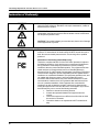
Amulet High Definition IP Television Receiver User‘s Guide (North America Edition) P/N: 95-83xxxx-06 V1.7 COPYRIGHT ©2009 Entone, Inc. All rights reserved. This document contains proprietary information protected by copyright. No part of this publication may be reproduced, stored in a retrieval system, or transmitted in any form or by any means, electronic, mechanical, photocopying, recording or otherwise, without the prior written consent of Entone, Inc., 20863 Stevens, Creek Blvd, Suite 300, Cupertino, CA 95014, U.S.A. DISCLAIMER IF THIS PRODUCT DIRECTS YOU TO COPY MATERIALS, YOU MUST HAVE PERMISSION FROM THE COPYRIGHT OWNER OF THE MATERIALS TO AVOID VIOLATING THE LAW WHICH COULD RESULT IN DAMAGES OR OTHER REMEDIES. TRADEMARKS Entone and the tagline “Connecting the Home” are trademarks of Entone, Inc. All other trademarks or registered trademarks belong to their respective owners. CHANGES The material in this document is for information only and is subject to change without notice. While reasonable efforts have been made in the preparation of this document to assure its accuracy, Entone, Inc. assumes no liability resulting from the use of the information contained herein. Entone, Inc. reserves the right to make changes in the product design without reservation and without notification to its users. P/N: 95-80xxxx-06 CUSTOMER SUPPORT AND CONTACT INFORMATION For Customer Support please call: 650.572.7000 Customer Contact Information: Entone, Inc. 20863 Stevens Creek Blvd Suite 300 Cupertino, CA 95014 U.S.A. Tel: 650.572.7000 www.entone.com V1.7 Amulet High Definition IP Television Receiver User’s Guide Table of Contents Declaration of Conformity ..................................................................................................................................... 2 Preface................................................................................................................................................................................ 5 TYPOGRAPHICAL CONVENTIONS ...................................................................................................................... 5 OVERVIEW OF THIS USER‘S GUIDE ................................................................................................................... 5 1 Safety Precautions ...................................................................................................................................................... 6 IMPORTANT SAFETY INSTRUCTIONS ................................................................................................................ 6 2 Index to Parts and Controls........................................................................................................................................ 8 CONTENTS IN THE BOX ........................................................................................................................................ 8 FRONT PANEL AND REAR PANEL ....................................................................................................................... 9 REMOTE CONTROL.............................................................................................................................................. 11 3 Amulet Introduction ................................................................................................................................................... 12 ABOUT THE AMULET HIGH DEFINITION IP TELEVISION RECEIVER .......................................................... 12 4 Connecting the TV .................................................................................................................................................... 13 CONNECTING THE TV USING COAXIAL CABLE ............................................................................................. 14 SETTING UP TV TO USE CATV........................................................................................................................... 14 CONNECTING TV USING RCA COMPOSITE OR S-VIDEO ............................................................................. 15 CONNECTING THE TV USING HDMI (CABLE NOT PROVIDED) OR COMPONENT ................................... 16 5 Connecting Audio System ........................................................................................................................................ 17 6 Connecting eSATA Hard Drive ................................................................................................................................ 18 7 Powering-Up Amulet................................................................................................................................................. 19 8 Remote Controls ....................................................................................................................................................... 21 LOADING BATTERIES .......................................................................................................................................... 21 CONTROLLING THE AMULET USING IR ........................................................................................................... 22 CONTROLLING YOUR TELEVISION AND OTHER A/V DEVICES .................................................................. 22 9 Specifications ............................................................................................................................................................ 23 10 Troubleshooting the Amulet ..................................................................................................................................... 25 1 Copyright 2010 Entone, Inc. All rights reserved Amulet High Definition IP Television Receiver User’s Guide Declaration of Conformity To ensure proper use of this product, please read this manual carefully and retain it for future reference. Should the unit require maintenance, contact an authorized service location. WARNING: This symbol indicates the presence of uninsulated dangerous voltage within the product's enclosure that constitutes a risk of electric shock. Do not open the product's case. CAUTION: This symbol indicates you must take care; there is risk of damage to the equipment or to yourself. To prevent fire or shock hazard, do not expose this product to rain or moisture. To reduce the risk of electric shock, DO NOT remove the cover or back. No user serviceable parts are inside. For servicing refer to qualified personnel. Declaration of Conformity (United States Only) This device complies with Part 15 of the FCC Rules. Operation is subject to the following conditions: (1) this device may not cause harmful interference, and (2) this device must accept any interference received, including interference that may cause undesired operation. This equipment has been tested and found to comply with the limits for a Class B digital device, pursuant to Part 15 of the Federal Communication Commission (FCC) Rules. These limits are designed to provide reasonable protection against harmful interference in a residential installation. This equipment generates, uses, and can radiate radio frequency energy, and if not installed and used in accordance with the instructions, may cause harmful interference to radio communications. However, there is no guarantee that interference will not occur in a particular installation. If this equipment does cause harmful interference to radio or television reception, which can be determined by turning the equipment OFF and ON, the user is encouraged to try to correct the interference by one or more of the following measures: Reorient or relocate the receiving antenna. Increase the separation between the equipment and the receiver. Connect the equipment to a different circuit from that to which the receiver is connected. Consult the dealer or an experienced radio/TV technician for help. 2 Copyright 2010 Entone, Inc. All rights reserved Amulet High Definition IP Television Receiver User’s Guide Part 68 - Compliance Registration This equipment complies with Part 68 of the FCC rules and the requirements adopted by the ACTA. A label on the bottom of this equipment contains, among other information, the Ringer Equivalence Number (REN) and the product identifier. For products approved after July 23, 2001 the product identifier is in the format US:AAAEQ##TXXXX. The digits represented by ## are the REN without a decimal point (e.g. 03 is a REN of 0.3). The REN is used to determine the number of devices that may be connected to a telephone line. For earlier products, the REN is separately shown on the label. If requested, this number must be provided to the telephone company. Excessive RENs on a telephone line may result in the devices not ringing in response to an incoming call. In most, but not all areas, the sum of RENs should not exceed five (5.0). To be certain of the number of devices that may be connected to a line, as determined by the total RENs, contact the local telephone company. This equipment is designed to connect to the telephone network or premises wiring using a compatible modular jack that is Part 68 compliant. An FCC compliant telephone cord and modular plug is provided with the equipment. If this terminal equipment causes harm to the telephone network, the telephone company may request you to disconnect the equipment until the problem is resolved. The telephone company will notify you in advance if temporary discontinuance of service is required. If advance notification is not practical, the telephone company will notify you as soon as possible. You will be advised of your right to file a complaint with the FCC if you believe such action is necessary. If you experience trouble with this equipment, do not try to repair the equipment yourself. The equipment cannot be repaired in the field. Contact your ISP for further instructions. The telephone company may make changes to their facilities, equipment, operations, or procedures that could affect the operation of this equipment. If this happens, the telephone company will provide advance notice in order for you to make the modifications necessary to maintain uninterrupted service. If your home has specially wired alarm equipment connected to the telephone line, ensure that the installation of this equipment does not disable your alarm equipment. If you have questions about what will disable alarm equipment, consult your telephone company or a qualified installer. This equipment cannot be used on public coin phone service provided by the telephone company. Connection of this equipment to party line service is subject to state tariffs. Declaration of Conformity (Europe Only) This product is in conformity with the Council Directives: EMC Directive 89/336/EEC Low voltage Directive 73/23/EEC Entone products are designed and tested to meet IEC60065, the standard for the Safety of Information Technology Equipment. This is the international standard for these types of products to reduce the risk of product damage and of personal injury. The standard protects against the following hazards: Electric shock Hazardous voltage levels Fire — Overload, temperature, material flammability Energy — Circuit with high energy or potential as burn hazards Heat — Accessible part of the product at high temperatures Radiation Noise 3 Copyright 2010 Entone, Inc. All rights reserved. Amulet High Definition IP Television Receiver User’s Guide Canada Certification Notice The Industry Canada label identifies certified equipment. This certification means that the equipment meets certain telecommunications network protective operations and safety requirements as prescribed in the appropriate Terminal Equipment Technical Requirements document(s). The department does not guarantee the equipment will operate to the user‘s satisfaction. This equipment meets the applicable Industry Canada Terminal Equipment Technical Specification. This is confirmed by the registration number. The abbreviation, IC, before the registration number signifies that registration was performed based on a Declaration of Conformity indicating that Industry Canada technical specifications were met. It does not imply that Industry Canada approved the equipment. The Ringer Equivalence Number (REN) is 0.0. The Ringer Equivalence Number that is assigned to each piece of terminal equipment provides an indication of the maximum number of terminals allowed to be connected to a telephone interface. The termination on an interface may consist of any combination of devices subject only to the requirement that the sum of the Ringer Equivalence Numbers of all the devices does not exceed 5.0. Before installing this equipment, users should ensure that it is permissible to be connected to the facilities of the local Telecommunication Company. The equipment must also be installed using an acceptable method of connection. The customer should be aware that compliance with the above conditions may not prevent degradation of service in some situations. Connection to a party line service is subject to state tariffs. Contact the state public utility commission, public service commission, or corporation commission for information. If your home has specially wired alarm equipment connected to the telephone line, ensure that the installation of this equipment does not disable your alarm equipment. If you have questions about what will disable alarm equipment, consult your telephone company or a qualified installer. If you experience trouble with this equipment, do not try to repair the equipment yourself. The equipment cannot be repaired in the field and must be returned to the manufacturer. Repairs to certified equipment should be coordinated by a representative, and designated by the supplier. Users should ensure, for their own protection, that the electrical ground connections of the power utility, telephone lines, and internal, metallic water pipe system, if present, are connected together. This precaution may be particularly important in rural areas. CAUTION: Users should not attempt to make such connections themselves, but should contact the appropriate electrical inspection authority, or electrician, as appropriate. 4 Copyright 2010 Entone, Inc. All rights reserved. Amulet High Definition IP Television Receiver User’s Guide Preface TYPOGRAPHICAL CONVENTIONS The following typographic conventions are used in this manual to provide visual clues as to the purpose or specific features of the Set-Top-Box (STB) application. Bold text describes menu options and selections displayed on the screen. Italics emphasize statements and points to reference documentation. Ellipses (…) indicate truncated text for long examples depicting output that is too long to be shown in its entirety. NOTE/TIP: A note or a tip describes actions or conditions that can help you obtain optimum performance from STB. WARNING: A caution or a warning describes conditions that can result in an error. IMPORTANT: An important note. OVERVIEW OF THIS USER’S GUIDE This User‘s Guide provides generic information about connecting Amulet to your audio and video equipments. Some of the topics covered in this guide are: Safety and regulatory information Setup Connecting Amulet to your audio and video equipment Connecting Amulet to the network Powering Amulet Using the Remote Controls Troubleshooting For a full listing of all of the topics covered in this User‘s Guide, see the Table of Contents. 5 Copyright 2010 Entone, Inc. All rights reserved. Amulet High Definition IP Television Receiver User’s Guide Chapter 1 1 Safety Precautions Before installing Amulet, be sure to unplug Amulet, your TV and any other audio-video equipment you are using. This precaution will help to prevent danger of electrical shock and damage to Amulet and your equipment. Be careful when moving your television to avoid accidental tipping or movements that might cause injury to you or those around you. To ensure proper use of this product, please read this user manual carefully and retain for future reference. Should the unit require maintenance, contact your service provider. IMPORTANT SAFETY INSTRUCTIONS 6 WARNING: To prevent fire or shock hazard, do not expose this product to rain or moisture. Read these instructions. Keep these instructions. Heed all warnings. Follow all instructions. Do not use this apparatus near water. Clean only with dry cloth. Do not block any ventilation openings. Install in accordance with the manufacturer‘s instructions. Do not defeat the safety purpose of the polarized or grounding-type plug. A polarized plug has two blades with one wider than the other. A grounding type plug has two blades and a third grounding prong. The wide blade or the third prongs are provided for your safety. If the provided plug does not fit into your outlet, consult an electrician for replacement of the obsolete outlet. Protect the power cord from being walked on or pinched particularly at plugs, convenience receptacles, and the point where they exit from the apparatus. Only use attachments/accessories specified by the manufacturer. Use only with the cart, stand, tripod, bracket, or table specified by the manufacturer, or sold with the apparatus. When a cart is used, use caution when moving the cart/apparatus combination to avoid injury from tip-over. Unplug this apparatus during lightning storms or when unused for long periods of time. Refer all servicing to qualified service personnel. Servicing is required when the apparatus has been damaged in any way, such as power-supply cord or plug is damaged, liquid has been spilled or objects Copyright 2010 Entone, Inc. All rights reserved Amulet High Definition IP Television Receiver User’s Guide have fallen into the apparatus, the apparatus has been exposed to rain or moisture, does not operate normally, or has been dropped. 7 To reduce the risk of electric shock, DO NOT remove cover or back. No user serviceable parts inside. Refer servicing to qualified personnel. To help prevent electric shock, plug the power cable into properly grounded sources. Use only properly grounded extension cords and adaptors, if they are needed. The AC main plug is used as the disconnect device, the disconnect device shall remain readily operable. Make sure nothing is lying on any of the cables. Be sure the cables are located where they will not be stepped on or tripped over. Do not spill food or liquids onto the unit. Do not push any objects into the free slots. Doing so will damage the unit, can cause fire or electrical shock, and can short out interior components. Do not install near any heat sources such as radiators, heat registers, stoves, or other apparatus (including amplifiers) that produce heat. Do not block cooling vents. Do not place the equipment in a closed-in wall unit. When you disconnect a cable, pull on its connector or on its strain relief loop, not on the cable itself. Some cables have a connector with locking tabs; if you are disconnecting this type of cable, press in on the locking tabs before disconnecting the cables. When you connect a cable, make sure both connectors are correctly oriented and aligned before connecting to avoid bending connector pins. For PLUGGABLE EQUIPMENT, the socket-outlet shall be installed near the equipment and shall be easily accessible. Changes or Modifications not expressly approved by the party responsible could void the user‘s authority to operate this device. Copyright 2010 Entone, Inc. All rights reserved. Amulet High Definition IP Television Receiver User’s Guide Chapter 2 2 Index to Parts and Controls CONTENTS IN THE BOX Item Picture Quantity Amulet High Definition IP Television Receiver (Amulet HD) 1 RF Cable (Type-F connector) (6ft) 1 RJ45 Ethernet Cable (10ft) 1 RCA A/V Cable (6.5ft) 1 Component Cable (6.5ft) 1 Power Supply with 1.8m power cord (100-240V, output 12V/2A) 1 Wireless Antenna (optional) 3 URC 4 Remote Control (Universal Remote Control) 1 Battery (AA-size) 2 8 Copyright 2010 Entone, Inc. All rights reserved Amulet High Definition IP Television Receiver User’s Guide FRONT PANEL AND REAR PANEL Figure 2-1 Amulet Front Panel Part Name 1. POWER 2. 3. 4. 5. 6. 7. USB LINK Indicator HD Indicator RECORD Indicator MENU Arrow Keys and OK Button Description If held for less than 5 seconds, turns the Amulet HD TV receiver ON/OFF. Lights blue when the receiver is turned on. If held for longer than 5 seconds, the Amulet HD TV receiver will be restarted. USB connector Green when Ethernet connection is active Blue when the output resolution is HD (720p or higher) Red when PVR (Personal Video Recording) is recording Display the User Menu OK Button for triggering remote registration mode Other usage according to middleware Figure 2-2 Amulet Rear Panel Part Name 1. 2. 3. 4. 5. 6. 7. 8. 9. 10. 11. 9 ANTENNA SATA CH4/CH3 Switch REMOTE CONTROL COAX VIDEO Y VIDEO VIDEO PB AUDIO LEFT VIDEO PR AUDIO RIGHT Description Connector for wireless antenna (optional) Connector for connecting external eSATA harddisk drive Switch for toggling the RF TV default channel (either channel 3 or channel 4) RF Type-F connector for connecting the RF remote control antenna (optional) RF Type-F connector for decoder Component Video output (Y) Composite video Component Video output (PB) Composite audio output (channel left) Component Video output (PR) Composite audio output (channel right) Copyright 2010 Entone, Inc. All rights reserved. Amulet High Definition IP Television Receiver User’s Guide 12. 13. 14. 15. 16. 17. 18. 10 ANTENNA OPTICAL AUDIO S-VIDEO HDMI USB ETHERNET DC Connector for wireless antenna (optional) S/PDIF digital optical audio TOSLINK output S-Video output HDMI output USB connector RJ45 plug for connecting to ADSL modem or network access equipment DC power jack Copyright 2010 Entone, Inc. All rights reserved. Amulet High Definition IP Television Receiver User’s Guide REMOTE CONTROL Part Name Description 1. TV Selects to control TV 2. STB Puts remote control in STB mode. 3. POWER Switches the power on/off for the currently selected device. Switches STB to power on / standby mode. 4. AUX Selects to control AUX device. 5. REW Starts fast reverse for VOD / PVR / live channel 6. REPLAY Replays the video from earlier position for VOD / DVR. 7. PLAY Play button for VOD / PVR / live channel 8. STOP Stop button for VOD / PVR / live channel 9. RED / DVR Red color button (usage depending on middleware application) 10. GREEN / LIVE TV Green color button (usage depending on middleware application) 11. MENU Shows the on-screen menu. 12. OPTIONS Usage depending on middleware or software application 13. ARROW KEYS Navigates right, left, up, down in the on-screen guide. 14. BACK Back button for on-screen menu (usage depending on middleware application) 15. GUIDE Shows the electronic program guide. 16. VOL + /- Increases or decreases volume of the currently selected device. Figure 2-3 Remote Control 17. MUTE Turns the volume of the currently selected device off. NOTE: *Please refer to your service operator or middleware application for detailed functions and usages. 18. NUMBER KEYS Allows direct access to specific channels and menu items. 19. INPUT Changes the current A/V input of the selected device. 20. FF Starts fast forward for VOD / DVR / live channel 21. SKIP Skips forward the video for VOD / DVR. 22. PAUSE Pause button for VOD / DVR / live channel 23. REC Records live channel. To be used with your DVR functionality. 24. BLUE / VOD Blue color button (usage depending on middleware application) 25. YELLOW / MEDIA Yellow color button (usage depending on middleware application) 26. INFO Shows on-screen information about the current TV / VOD / DVR program. 27. OK Executes the currently selected menu option. 28. EXIT Exits the current menu item. 29. CH UP/DOWN Changes channel up or down. 30. LAST Changes channel to the most recently viewed channel. 31. CC Toggles closed captioning on or off. 11 Copyright 2010 Entone, Inc. All rights reserved. Amulet High Definition IP Television Receiver User’s Guide Chapter 3 3 Amulet Introduction ABOUT THE AMULET HIGH DEFINITION IP TELEVISION RECEIVER Amulet High Definition IP Television Receiver is one of Entone‘s line of cost-effective and compact highdefinition Customer Premise Equipment (CPE) solutions. Amulet is a multi-functional IPTV receiver with MPEG-4 (AVC/H.264) HD capabilities that integrates easily with popular home-networking and broadband services. It also features an optional integrated digital video recording (DVR). These robust features enable service providers to increase their subscriber base and generate more revenue by offering enhanced services. Amulet‗s external hard drive option allows service providers to offer advanced services such as DVR without the hassles of installing new equipment. The optional DVR provides up to 400 hours of SD content or 200 hours of HD content. With Amulet, operators can now deliver more compelling services and an enhanced user experience to their subscribers. With Amulet, subscribers can blend and connect a variety of traditional DSL broadband services (FTTP) with rich media services, and extend the capabilities of their existing IP home networks. Amulet supports a broad range of established home networking technologies such as HomePlug, HomePNA 3.0 and 802.11n to distribute video content throughout the home, including isolated locations. Amulet can also connect with a home computer for more content-delivery choices. NOTE: HomePlug, HomePNA 3.0 and 802.11n are Amulet optional features. 12 Copyright 2010 Entone, Inc. All rights reserved Amulet High Definition IP Television Receiver User’s Guide Chapter 4 4 Connecting the TV Amulet offers several options for connecting audio and video to popular TV and audio equipment. You can connect Amulet to the primary TV using composite, component or HDMI connection. You may also connect the Amulet to TVs located in other rooms using coaxial cable connection. (RF remote controls can be ordered separately to control the Amulet from other rooms.) If your TV supports 480p, 720p or 1080i pictures, use the HDMI or the component output jacks to connect to your TV. HDMI stands for High Definition Multimedia Interface. HDMI transfers digital audio and uncompressed digital video on a single cable. As a result, audio cables and video cables do not need to be connected separately. The HDMI output jack is fully compliant to HDMI 1.3 specifications. HDMI and component video output support high definition video signal. They will provide the best quality video signal for HD ready TV sets. 13 Copyright 2010 Entone, Inc. All rights reserved Amulet High Definition IP Television Receiver User’s Guide CONNECTING THE TV USING COAXIAL CABLE 1. 2. Use the coaxial cable that comes with Amulet to connect your TV‘s antenna input to the Amulet‘s ―COAX‖ connector. Tune your TV to channel 3 or channel 4 to view the output (depending on selection of the CH3/CH4 switch at the rear panel). NOTE: In the RF TV, factory set to use channel 3 or channel 4. To set RF TV to another channel ID, You can change the channel ID by toggling the CH3/CH4 switch at the rear panel. NOTE: The new channel ID will take effect immediately after the switch is toggled. Figure 4-1 Connecting TV using Coaxial Cable SETTING UP TV TO USE CATV In order for the Amulet to feed video signal to TV using RF TV, your TV must be configured to receive signal from CATV rather than from the antenna. Most TVs use either a physical switch located on the rear of the TV or with on-screen programming to configure to use CATV. Consult your TV owner‘s manual for instruction if required. 14 Copyright 2010 Entone, Inc. All rights reserved. Amulet High Definition IP Television Receiver User’s Guide CONNECTING TV USING RCA COMPOSITE OR S-VIDEO 1. Acquire the required cable. RCA cable comes packaged with the Amulet. S-Video cable is not packaged with the Amulet. Before purchasing the cable, consult your TV owner‘s manual to confirm that your TV supports the video signal output that you plan to use. 2. Connect the video and audio cables to the Amulet. 3. Connect the opposite end of the video and audio cables to the matching input in the TV. 4. Plug in your TV and turn on the power using your TV remote control. Use your TV remote control to select the respective video input that has connected to the Amulet. Consult your TV owner‘s manual for instructions as required. 5. Plug in your Amulet and turn on the power. 6. You should now see the output from the Amulet on your TV screen. Figure 4-7 Connecting TV using RCA Composite Video/Audio 15 Figure 4-8 Connecting Primary TV using S-Video and Composite Audio Copyright 2010 Entone, Inc. All rights reserved. Amulet High Definition IP Television Receiver User’s Guide CONNECTING THE TV USING HDMI (CABLE NOT PROVIDED) OR COMPONENT 1. Acquire the required cable. Component cable comes packaged with the Amulet. HDMI cable is not packaged with the Amulet. Before purchasing the cable, consult your TV owner‘s manual to confirm that your TV supports the video signal output that you plan to use. 2. Connect the video and audio cables to the Amulet. (HDMI does not require separate audio cable connection.) 3. Connect the opposite end of the video and audio cables to the matching input in the TV. 4. Plug in your TV and turn on the power using your TV remote control. Use your TV remote control to select the respective video input that has connected to the Amulet. Consult your TV owner‘s manual for instructions as required. 5. Plug in your Amulet and turn on the power. 6. You should now see the output from the Amulet on your TV screen. Figure 4-9 Connecting TV using Component and Composite Audio Figure 4-10 Connecting TV using HDMI NOTE: When the HDMI connection cannot be verified by your TV, disconnect the HDMI cable and then connect it again, or turn off the TV and then turn it on again. Analog DVI is not supported. If your TV supports digital DVI but not HDMI, you can use an HDMI to DVI convector cable or adaptor to connect the Amulet HDMI to the TV DVI. In this case, you need to connect the audio cable separately. Be sure to use an HDMI cable with the HDMI logo. If your TV does not support multi-channel audio, the Amulet will output PCM audio only. Please refer to the next section to set the Component and HDMI output resolution. 16 Copyright 2010 Entone, Inc. All rights reserved. Amulet High Definition IP Television Receiver User’s Guide Chapter 5 5 Connecting Audio System Your Amulet supports AC-3 (Dolby Digital 5.1 channel). To enjoy multi-channel surround-sound, the content source must carry multi-channel AC-3 signal. Please refer to your service provider for availability of AC-3 5.1 programs. You can enjoy multi-channel surround-sound such as 5.1 channels by connecting the Amulet to an amplifier compatible with Dolby Digital. You can connect to your amplifier using the digital optical audio output. Figure 5-1 Connecting Amulet to Audio System Consult your audio system user guide for connection. Take necessary precautions when working with electric equipment. Remove the devices from wall power and be sure to use caution when moving equipment to prevent injury. If your connected TV or A/V equipment does not support AC-3, you can disable AC-3. Enabling or disabling AC-3 is controlled by the IPTV middleware. For details of enabling and disabling AC3, please refer to usage instruction provided by your service operator. 17 Copyright 2010 Entone, Inc. All rights reserved. Amulet High Definition IP Television Receiver User’s Guide Chapter 6 6 Connecting eSATA Hard Drive Amulet supports DVR (Digital Video Recording) and PLTV (Pause Live TV) by using eSATA (External Serial Advanced Technology Attachment) hard disk drive. This section applies when you need to install an external eSATA hard drive. DVR allows you to record live or scheduled channel programs into the hard drive and view those recorded programs as VOD at later times. PLTV allows you to pause and fast track live programs. For details of DVR and PLTV service availability and operation usage, please refer to your network and TV service provider. eSATA hard drive is an optional item. eSATA is an external interface for SATA technologies. The SATA interface is more streamlined than ATA and provides serial architecture for greater speed than the older parallel technology. To get ready your Amulet to enable DVR and PLTV service: 1. Connect the external hard drive using eSATA cable. 2. The eSATA hard drive requires separate power supply. Connect the eSATA hard drive power supply to the power source. Figure 6-1 Connecting eSATA hard drive 18 Copyright 2010 Entone, Inc. All rights reserved. Amulet High Definition IP Television Receiver User’s Guide Chapter 7 7 Powering-Up Amulet Follow these steps to power up the Amulet: 1. Follow your TV/Network service provider‘s instruction to connect the Amulet to your network modem or network access unit using the Ethernet cable or Wireless Antennae (optional) Figure 7-1 Connecting Amulet (Ethernet connection) Figure 7-2 Connecting Amulet (Wireless connection) 2. Plug the socket end of the AC/DC adapter into the wall socket and the DC jack into the power connector on the Amulet. 3. The Amulet front panel power indicator will illuminate in blue color. 4. The ―LINK‖ LED indicator will illuminate in green color NOTE: The ―HD‖ LED indicator will illuminate only if the output resolution is 720p or higher. The ―RECORD‖ LED indicator will illuminate only if the (DVR) is enabled and recording assets to the hard disk drive is in progress. (Please refer to your middleware or service provider about the DVR functionality) 19 Copyright 2010 Entone, Inc. All rights reserved Amulet High Definition IP Television Receiver User’s Guide Figure 7-3 Amulet Starting 5. Within 60 seconds splash screen will appear on the TV. Figure 7-4 Amulet Boot-up Splash Screen 6. The total boot-up time may vary depending on the middleware application and the service provider environment. 20 Copyright 2010 Entone, Inc. All rights reserved. Amulet High Definition IP Television Receiver User’s Guide Chapter 8 8 Remote Controls LOADING BATTERIES The remote control comes with AA-size batteries, which needs to be installed when you first receive your system. When you replace old batteries, you should replace all of the batteries. Use batteries of the same kind, for example alkaline or carbon zinc, and do not mix batteries of different kinds. Alkaline batteries last longer than carbon zinc. WARNING: Mixing old and new batteries or different types of batteries poses a fire hazard. To load batteries to remote control: 1. Press down on the battery cover‘s top latch and slide the cover off. 2. If you are changing out batteries, take out all of the old batteries. 3. Put the new batteries in. Make sure you match the plus ( ―+‖ ) ends with the plus markings on the battery case. 4. Slide the cover back into place. Figure 8-1 Loading Batteries to Remote Control 21 Copyright 2010 Entone, Inc. All rights reserved Amulet High Definition IP Television Receiver User’s Guide CONTROLLING THE AMULET USING IR Amulet uses InfraRed (IR) to receive remote control signals. IR signals travel only short distances (40 feet or less), and cannot go through walls or other solid objects. You must point the remote control to the Amulet, with no objects blocking the line of sight. Figure 8-2 IR Reception Range CONTROLLING YOUR TELEVISION AND OTHER A/V DEVICES The Amulet remote controls can also be used to control TVs and other A/V devices such as DVD players and recorders. The remote controls use infrared (IR) light signals to control other devices that the remote is programmed to control. IR signals travel only short distances (40 feet or less), and cannot go through walls or other solid objects. You must point the remote control directly at these devices, with no objects blocking the line of sight. For details of how to program the Amulet remote controls and the supported devices, please refer to the Amulet Quick Reference Guide or URC 4 User’s Guide. 22 Copyright 2010 Entone, Inc. All rights reserved. Amulet High Definition IP Television Receiver User’s Guide Chapter 9 9 Specifications Main components Decoder Main CPU Memory Software Universal Remote Control Graphics Color Audio and video Video Input Formats Video Output Formats Audio Input Formats Audio Output Formats Closed Captioning Connectors 23 Single decoder MIPS 4380 class with FPU 512MB, 1GB NAND Flash Real-time, multi-threaded embedded OS, Java Virtual Machine with MHP APIs, HTML 4.01 compliant browser with JavaScript 1.5 IR carrier frequency is 36KHz using RC6 protocol True-color OSD support (up to 1920x1080 pixels) Programmable OSD scaler, flicker filter Alpha blending over video Picture in graphics with scaling 2-D graphic accelerator High profile up to level 4.1 H.264/AVC streams High or main profile level 3.1 H.264/AVC streams VC-1 SP/MP and AP @ level 3 HD MPEG-2 4:2:0 SD MPEG-2 4:2:0 Still picture decode MPEG4 P2 SP/ASP L5 SD Progressive/Interlaced DivX 3.11, 4.1, 5.x progressive and interlaced AVS1-P2 Jizhun profile level 6.0 NTSC-M, NTSC-J 480i/480p/720p/1080i output formats Component RGB or YPrPb Output Macrovision 7.1 HDMI with HDCP 1.2 S-video and composite AAC LC, AAC LC+SBR Level 2, AAC+ Level 2, AAC+ Level 4 Dolby Digital, Dolby Digital Plus MPEG I Layer 1, 2, 3 (MP3) Windows Media Audio (WMA) WMA pro AAC HE 5.1 decode plus DTS 5.1 encode SPDIF output AAC HE 5.1 decode plus AC3 5.1 encode SPDIF output S/PIDF output supports Dolby Digital, AAC, MPEG and DTS passthrough, 24-bit PCM Dolby Digital , AAC down mixed to 2 channel PCM analog stereo MPEG (ISO/IEC-11172-3) down mixed to 2 channel PCM analog stereo EIA-608 Captioning format – ATSC, SCTE 1 x RF TV type-F connector for 1 modulated channel 1 x RCA composite video output 1 x RCA composite audio output Copyright 2010 Entone, Inc. All rights reserved Amulet High Definition IP Television Receiver User’s Guide Tuner Network interfaces Ethernet Home networking Physical and mechanical Dimensions Weight Operating voltage Operating current Operating frequency Output voltage, current Operating temperature Relative Regulatory compliance Security controls Anti-Taping Parental Controls 1 x S-Video output 1 x YpbPr Component output 1 x HDMI (HDMI 1.3) 1 x S/PDIF digital optical audio TOSLINK output 1 x eSATA connector 1 x USB (USB 2.0) connector 3 x Optional SMA connectors None Ethernet (10/100Base-T auto-sensing) Optional HPNA 3.0 (Telephone wire / Coaxial Cable) Optional 802.11n wireless 160mm x 250mm x 50mm (W x L x H) 1 kg 100-240V AC RMS 0.6A 50/60Hz 12V DC, 2A 10° to 35° C (50° to 95° F) Humidity non-condensing UL/cUL, CE (pending), FCC part 15, FCC part 68 Macrovision (optional) Provided through middleware partner integration NOTE: Above specification for reference only. 24 Copyright 2010 Entone, Inc. All rights reserved. Amulet High Definition IP Television Receiver User’s Guide Chapter 10 10 Troubleshooting the Amulet This section describes some of the most common problems that might be encountered when installing Amulet, and the solutions to those problems. Symptom Remote controls do not work Remote controls cannot control the programmed devices Standby indicator at the front panel not lit Standby indicator on the front panel stays orange for more than 60 seconds Standby indicator turns green; no picture on the TV No sound 25 Remedy Check batteries are correctly loaded. Check that new URC 4 remote control is used. Check remote control is programmed to IR mode. In case of doubt, program the remote control again. Device manufacturers may change their device codes or no device code can be found in the Universal Remote Control User‘s Guide. Try searching the device code according to the procedures listed in the Universal Remote Control User‘s Guide. The power supply to the box is probably not working: Check that the AC/DC adapter is connected properly to the DC INPUT connector. Check that there is power from the power source. Make sure you have pressed the Standby button at the top of the box and that the Standby / On light is green. Check that the ADSL cable is properly connected between the ADSL connector and the ADSL modem. The ADSL Link indicator should be orange and steady. Check that the ADSL modem is properly connected to the telephone socket. Check that the video output connector of the Amulet is properly connected to the input connector of the primary TV. ―RF TV‖ (coaxial connection): the TV set should be set to channel 3/4. Composite, Component or HDMI connection: the TV set should be set to the correct input mode for the signal. Component or HDMI connection: the resolution selected in Amulet is supported by your TV. Check that the audio cable is connected to the correct input in your device. Is the volume of the device turned down to the minimum level? If HDMI or component is used. Try disabling Reference Section 8 – Remote Controls Amulet Quick Reference Guide URC 4 User‘s Guide Section 7 – Powering-Up Amulet Section 7 – Powering-Up Amulet Section 4 – Connecting the TV Section 5 – Connecting Audio System Copyright 2010 Entone, Inc. All rights reserved Amulet High Definition IP Television Receiver User’s Guide Multi-channel sound not working No sound, poor sound or popping noise on HDMI 26 AC-3. If HDMI is used, check the resolution and try to use the composite audio output. Check with service provider that programs contain multi-channel AC-3 signal. Check that AC-3 is enabled in the Amulet. Check your TV or A/V equipment for AC-3 multi-channel setup. HDMI is an evolving technology, so it is possible that some TVs may not operate properly with Amulet. In case of problem, use component video output and composite audio output to connect your primary TV. Section 5 – Connecting Audio System Section 4 – Connecting the TV Copyright 2010 Entone, Inc. All rights reserved.