1
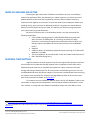
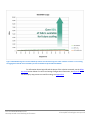
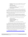
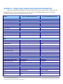
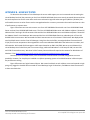
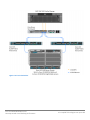
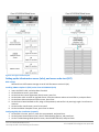
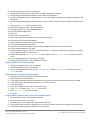
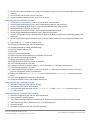
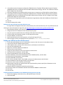
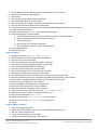
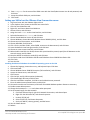
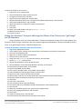
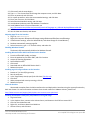
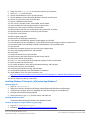
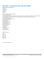
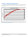
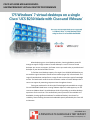
CISCO UCS B230 M2 BLADE SERVER: UNCOMPROMISED VIRTUAL DESKTOP PERFORMANCE u When deploying your virtual desktop solution, choosing hardware powerful enough to support a large number of virtual desktops is crucial. The more virtual desktops your server can support, the fewer servers you need to buy to provide virtual desktops to your desired number of users. To find the virtual desktop capacity of a single Cisco UCS B230 M2 Blade Server, we used the Login Consultants Virtual Session Indexer (Login VSI) 3.0 benchmark. The Login VSI workload we used performs a range of tasks to simulate a typical knowledge worker. The benchmark results show the maximum number of virtual desktops that a server can support by measuring response times throughout the test. Testing we conducted in the Principled Technologies lab revealed that a single Cisco UCS B230 M2 Blade Server running VMware vSphere 5 could support up to 175 concurrent VMware View 5 virtual desktops while still providing an excellent desktop experience for the end-user. This workload only used 5 percent of the available UCS bandwidth, leaving significant headroom for additional blades in the chassis for scalability, demonstrating the extensive bandwidth capacity afforded by the Cisco UCS architecture. DECEMBER 2011 A PRINCIPLED TECHNOLOGIES TEST REPORT Commissioned by Cisco Systems, Inc. MORE VDI SESSIONS ARE BETTER Choosing the right combination of hardware and software for your virtual desktop solution can significantly affect your bottom line. A robust hypervisor, top-of-the-line virtual desktop software, and a server built on powerful processors with an expansive memory footprint all work together to ensure you can meet the needs of your employees without your spending money, space, and time on additional hardware. The greater your virtual desktop density, the fewer physical servers you need. This reduces your electricity usage and power costs, and results in a greener datacenter. We set out to examine such a virtual desktop solution, one that consisted of the following components: Cisco Unified Computing System™ (UCS) B230 M2 Blade Server with Intel® Xeon® processor E7-4870s (Note: In our testing, we used the E7-4870 processors, the functional and performance equivalent of the E7-2870. Cisco officially supports the 2800 series of Intel Xeon processors for the B230 M2 blade.)1 vSphere 5 A VMware View 5 virtual desktop linked clone pool consisting of 175 Microsoft® Windows® 7 x64 VMs 175 virtual desktops, all provisioned with 1 vCPU and 2 GB of reserved memory2 EMC® VNX 5500 storage array RESPONSE TIME MATTERS Login VSI measures the total response times of seven typical office operations and from that calculates the VSI Index and average response times. Completion of these tasks within 4,000 milliseconds makes for an acceptable user experience. Figure 1 shows the VSI index average and average response times for all active sessions recorded during the test. The Cisco UCS B230 M2 Blade Server was able to support 175 concurrent virtual desktops without crossing the response-time threshold. User response time degraded only when all 20 processor cores were nearly saturated. For details, see Appendix D. To initiate our test, we enabled our VMware View 5 pool of 175 Windows 7 VMs to start up and reach a ready state. We monitored our test bed and perceived no bottlenecks in server CPU, network, or storage I/O at the VMware View default startup rate of five VMs at a time. 1 See http://www.intel.com/content/www/us/en/processors/xeon/xeon-e7-8800-4800-2800-families-vol-1-datasheet.html. We used 2 GB of RAM because Microsoft Windows 7 64-bit requires it. See http://windows.microsoft.com/en-US/windows7/products/systemrequirements. 2 Cisco UCS B230 M2 Blade Server: Uncompromised virtual desktop performance A Principled Technologies test report 2 Response time for virtual desktops on a single Cisco UCS B230 M2 Blade Server 5,000 Milliseconds 4,000 Average Response 3,000 VSI Index average 2,000 1,000 6 14 20 27 34 40 47 54 61 68 74 80 87 94 100 106 112 119 125 132 138 144 150 157 163 169 175 0 Number of virtual desktop sessions Figure 1: Average virtual desktop response times at various numbers of virtual desktops on the Cisco UCS B230 M2 Blade Server. GREATER BANDWIDTH HEADROOM PROVIDES EXCELLENT SCALABILITY Although the Cisco UCS offers scalable bandwidth to each Cisco UCS 5108 Chassis, up to a fully redundant 40 Gb/s, in our testing we used a single redundant pair of 10Gb connections to the fabric interconnect. Figure 2 shows that the peak bandwidth usage of the 175 concurrent virtual desktop sessions never exceeded 450 megabits per second, or roughly 5 percent of the bandwidth available. Note that this includes all storage and virtual desktop traffic. This shows that the chassis capacity far exceeds the required bandwidth for virtual desktop users based on our Login VSI test results. The bandwidth afforded by the Cisco UCS architecture provides sufficient headroom for excellent scalability as your IT staff adds more Cisco UCS B230 M2 server blades to support larger user populations. Cisco UCS B230 M2 Blade Server: Uncompromised virtual desktop performance A Principled Technologies test report 3 Figure 2: Bandwidth usage for 175 virtual desktop sessions over the hour-long test. Lower numbers are better. In our testing, the aggregate workload never exceeded 5 percent of available compute fabric bandwidth. For information about Login VSI and the pieces of the solution we tested, see the What we tested section below. For server and storage configuration information, see Appendix A. To see the step-by-step process we used for testing, see Appendix B. Cisco UCS B230 M2 Blade Server: Uncompromised virtual desktop performance A Principled Technologies test report 4 WHAT WE TESTED About the Cisco UCS B230 M2 Blade Server We used a VDI-optimized, dual-socket Cisco UCS B230 M2 Blade Server with a pair of Intel 10-core, 2.4 GHz Xeon (2800/4800 series) processors, two 32GB Intel X-25E SATA SSDs, and 512 GB of system memory. We installed a Cisco M81KR Virtual Interface Card (VIC) into the server, which is a dual-port 10Gb Converged Network Adapter (CNA) optimized for virtualization. The M81KR supports up to 128 PCIe-compliant virtual interfaces and Cisco VNLink technology. The VIC ensures reliable 10Gb, low-latency connectivity to SAN and LAN, while allowing for greater flexibility and ease of management. Additionally, the Cisco UCS B230 M2 blade server provides support for two hot-swappable SSD drives that are accessible from the front of the server, and for an LSI SAS2108 RAID controller. The UCS B230 server also comes with one dual-port mezzanine card that can provide up to 20 Gbps I/O per blade. To learn more, see Appendix A for more detailed hardware specifications, or visit http://www.cisco.com/en/US/products/ps11583/index.html. About the Cisco UCS Manager The Cisco UCS Manager enables unified, embedded management that integrates the management of both software and hardware on the Cisco UCS solution. The UCS Manager centralizes server management, making it easier in several key ways. First, role-based management makes it easy to assign unique management roles to different administrators (i.e., server, network, or storage admins) so that each can be assigned his or her own unique policies and permissions, while still being part of an integrated management environment. Policy-based provisioning provides managers with the ability to create service profile templates that they apply to one or 100 servers, making it easy to apply consistent policies. The Cisco USC Manager makes server management less about managing isolated, single hardware components and more about managing many hardware components (up to 40 chassis and 320 blades) as a single management domain. The use of service profiles allows managers to allocate and reallocate server resources, which the UCS Manager views as “raw computing capacity.” This way, server capacity allocation becomes more dynamic and efficient, with managers able to deploy and reallocate server resources in a matter of minutes. To learn more about the Cisco UCS Manager, visit http://www.cisco.com/en/US/products/ps10281/index.html. About VMware View 5 VMware designed its View 5 desktop virtualization software to simplify IT management of virtual desktops from within the cloud. A centralized interface allows administrators to manage upwards of tens of thousands of end-users. An administrator can easily manage settings such as policy enforcement, performance monitoring, connection brokering, and provisioning, to name a few. The result includes improved security, less costly management, and faster Cisco UCS B230 M2 Blade Server: Uncompromised virtual desktop performance A Principled Technologies test report 5 provisioning and maintenance of desktop images and applications. The end-user enjoys easier access to his or her View desktop from a variety of locations, less downtime, a customizable desktop, and robust multimedia capabilities. In our tests, we implemented a new feature of View 5, that of PCoIP Optimization Controls. This feature helps IT administrators better configure bandwidth settings (by user, use case, or network requirements), which can reduce bandwidth by up to 75 percent and improve protocol efficiency. To learn more about VMware View 5, visit http://www.vmware.com/products/view/overview.html. About VMware vSphere 5 vSphere 5 is the latest virtualization operating system from VMware. vSphere 5 allows companies to virtualize their server, storage, and networking resources, achieving a consolidation ratio greater than 15:1. Features such as automated management and dynamic resource allocation improve efficiency. The services that vSphere 5 provides fall into two categories: Infrastructure services or application services. The former handle the virtualization of resources and their allocation to application when most needed, while the latter provide service-level controls to applications running on vSphere 5. To learn more about VMware vSphere 5, visit http://www.vmware.com/products/vsphere/overview.html. About the Intel Xeon Processor E7-2800 series The Intel Xeon processor E7-2800 series—the next generation of Intel Xeon multi-core processors—is optimized for MP configurations in enterprise application servers. These processors use Intel QuickPath Interconnect Technology to enable up to 30 MB of shared cache. The Intel Xeon processorE7 family also support advanced Intel features like Intel 64 technology, Enhanced Intel SpeedStep®, and Intel Virtualization technology. The E7-2800 series is available with 6, 8, or 10 cores per socket. To learn more about the Intel Xeon processor E7-2800 series, visit http://www.intel.com/content/www/us/en/processors/xeon/xeon-e7-8800-4800-2800families-vol-1-datasheet.html About Login VSI Login VSI benchmarks virtual desktop sessions to determine how scalable a particular virtualized system is. Specifically, it benchmarks a virtual desktop solution by simulating Windows-based Office user workloads. The Medium workload of Login VSI, which we tested as indicative of a typical “knowledge worker,” opens and closes the following applications and runs their respective tasks: Microsoft Outlook®: Browsing a message Microsoft Word® (TimerDoc): Initiating response timer to see how the program responds throughout the workload Microsoft Internet Explorer® instance one: Maximizing, scrolling, and minimizing Cisco UCS B230 M2 Blade Server: Uncompromised virtual desktop performance A Principled Technologies test report 6 Microsoft Internet Explorer instance two: Navigating a Web site, maximizing, and scrolling Microsoft Word (UserRead): Reading and typing text, and printing to PDF Bullzip: Generating a PDF Adobe® Reader®: Reading a PDF Microsoft PowerPoint®: Watching a presentation and adding a slide Microsoft Excel®: Reading and minimizing 7-Zip: Saving a ZIP file Login VSI Version 3.0 (Release 6) benchmarks user experience more effectively than previous versions of Login VSI because its workloads and what the VSI Index measures more accurately reflect the tasks actual users perform on their virtual desktops. Reported response times are higher in Login VSI 3.0 than in Login VSI 2.0 and other previous versions because the benchmark uses this heavier workload. The Login VSI benchmark mandates the minimum acceptable response time for the testing. The Login VSI 3.0 benchmark uses seven operations to determine the VSImax, the maximum number of users the system can handle before suffering serious degradation in performance. By using seven operations instead of only two, as earlier versions of Login VSI did, Login VSI 3.0 better reflects what a user actually experiences. The seven operations are as follows: Copying a new document from the document pool in the home drive Starting Microsoft Word Starting the File Open dialogue Starting the Search and Replace dialogue Starting the Print dialogue Starting Notepad Compressing the document into a ZIP file with 7-zip command line Login VSI reports minimum, average, and maximum response times, as well as the VSI Index average while performing the workload. The Login VSI Index average is similar to the average response time, as it averages the maximum and minimum response times, but it removes 2 percent from the maximum and minimum response time before calculating the average. The response times are reported in time in milliseconds to perform the workload tasks. The Login VSImax is the total number of virtual desktops the server can support while still maintaining a response time of 4,000 milliseconds (4 seconds) or below, and is based on the VSI Index average. In our testing at 175 sessions, the server still did not reach Login VSImax, indicating that the server could handle the load with processor and storage resources to spare. For more information on Login VSI 3.0, see http://www.loginconsultants.com/index.php?option=com_content&task=view&id=390. Cisco UCS B230 M2 Blade Server: Uncompromised virtual desktop performance A Principled Technologies test report 7 SUMMARY A server that will support greater density of hosted virtual desktops without sacrificing performance will minimize the cost of your infrastructure and improve ROI. In our tests, the Cisco UCS B230 M2 Blade Server running VMware View 5 with VMware vSphere 5 provided impressive virtual desktop hosting density. The Cisco UCS solution delivered 175 concurrent VMware View 5 virtual desktops with acceptable user response times and minimal bandwidth usage. Cisco UCS B230 M2 Blade Server: Uncompromised virtual desktop performance A Principled Technologies test report 8 APPENDIX A – SERVER AND STORAGE CONFIGURATION INFORMATION Figure 3 provides detailed configuration information about the test servers. Note that we used the Cisco UCS B230 M2 Blade Server for the systems under test and used the Cisco UCS B200 M2 Blade Server for our testbed infrastructure. Figure 4 details the storage we used in our tests. System Enclosure Blade enclosure Power supplies Total number Wattage of each (W) Cooling fans Total number Dimensions (h x w) of each General Number of processor packages Number of cores per processor Number of hardware threads per core CPU Vendor Name Model number Stepping Socket type Core frequency (GHz) Bus frequency (GT/s) L1 cache L2 cache L3 cache (MB) Platform Vendor and model number Motherboard model number Motherboard chipset BIOS name and version BIOS settings Memory module(s) Total RAM in system (GB) Vendor and model number Type Speed (MHz) Speed running in the system (MHz) Cisco UCS B230 M2 Blade Server Cisco UCS B200 M2 Blade Server Cisco UCS 5108 Cisco UCS 5108 4 2,500 4 2,500 8 3-5/8" x 5-1/2" 8 3-5/8" x 5-1/2" 2 10 2 6 2 2 Intel Xeon E7-4870 (functionally the same as the E7-2870 in a two-socket configuration) A2 (SLC3T) LGA 1567 2.40 6.4 32 KB+ 32 KB (per core) 256 KB (per core) 30 Intel Xeon Cisco UCS B230 M2 Blade Server B230-Base-M2 Intel 7500 B230.2.0.1c.100520111716 Default Cisco UCS B200 M2 Blade Server N20-B6625-1 Intel 5520 Cisco S5500.2.0.1d.093030111102 Default 512 Samsung M393B2K70CMB-YF8 DDR3 PC3-8500 1,067 96 Samsung M393B5170FH0-YH9 DDR3 PC3-10600 1,333 1,067 1,333 Cisco UCS B230 M2 Blade Server: Uncompromised virtual desktop performance X5670 CO LGA 1366 2.93 6.4 32 KB+ 32 KB (per core) 256 KB (per core) 12 A Principled Technologies test report 9 System Size (GB) Number of RAM module(s) Chip organization Hard disk Vendor and model number Number of disks in system Size (GB) RPM Type Controller Operating system Name File system Kernel Language Network adapter (mezzanine card) Vendor and model number Cisco UCS B230 M2 Blade Server Cisco UCS B200 M2 Blade Server 16 32 Double-sided 8 12 Double-sided Intel X-25E SATA SSD 2 32 N/A SATA LSI™ MegaRAID® 9240 Seagate ST9146803SS 2 146 10,000 SAS LSI Logic® SAS 1064E VMware vSphere 5 (504890) VMFS 5.0.0 English VMware vSphere 5 (504890) VMFS 5.0.0 English 1 x Cisco UCS M81KR Virtual Interface Card 1 x Cisco UCS M71KR-Q QLogic® Converged Network Adapter Figure 3: Detailed configuration information for the servers. System Storage Number of 15-disk processor enclosures Power supplies Total number Disk array enclosures Number of 25-disk array enclosures Number of 15-disk array enclosures Data movers Number of VNX 5500 data movers Disks Number of 100GB SSDs Number of 300GB SAS drives Number of 2TB NL SAS drives Operating system Name Network Vendor and model number EMC VNX 5500 storage array 1 2 1 1 1 8 20 10 Unisphere 10 Gb NFS Figure 4: Detailed configuration information for the storage. Cisco UCS B230 M2 Blade Server: Uncompromised virtual desktop performance A Principled Technologies test report 10 APPENDIX B - HOW WE TESTED To determine the number of virtual desktops the server could support, we ran incremental tests increasing the virtual desktop load until the processors on the Cisco UCS B230 M2 Blade Server were nearly saturated. We ensured that the total response time for the seven office tasks never achieved a Login VSI Index average of 4,000 ms (VSI Max). We confirmed there were no other factors such as storage bottlenecks or memory constraints that could contribute to a loss of performance or response time. Figure 5 illustrates our test environment: one Cisco UCS 5108 Blade Chassis with one Cisco UCS B230 M2 Blade Server and one Cisco UCS B200 M2 blade server. The Cisco UCS B200 M2 blade server with VMware vSphere 5 hosted all VMware View 5 and Login VSI Infrastructure VMs and the Cisco B230 M2 blade server with VMware vSphere 5 hosted all the VMware View 5 virtual desktops. We connected the Cisco UCS 5108 Blade Chassis to redundant pair of Cisco UCS 6120XP Fabric Interconnects. We connected the Fabric Interconnects to a Cisco Nexus™ 5010 switch. We deployed the two Cisco blade servers via the Cisco UCS Manager. Using Cisco Service Profiles, we assigned a Base firmware level of 2.0(1s) for all server components. We assigned each server two redundant 10Gb vNICs that had access to our data, and NFS networks. We hosted all VM storage on a NFS export hosted on an EMC VNX 5500. We set up our VMware View virtual desktops via a linked clone pool. Our master image, a Microsoft Windows 7 x 64 Enterprise VM, has one vCPU and 2 GB of reserved memory. We chose 2 GB of memory because Microsoft requires that amount for x64 editions of Windows 7. See http://windows.microsoft.com/en-US/windows7/products/system-requirements. Note that, for its UCS blade servers, Cisco recommends a stateless boot from SAN configuration to ensure portability. However, for simplicity we installed our vSphere operating system on local disks because it did not impact the performance testing. Figure 6 illustrates our logical network layout. We created a vSwitch on each vSphere server and created a single port group, tagged as vlan100. We connected all virtual desktops, Login VSI launchers, and VMware view infrastructure to these two vSwitches. Cisco UCS B230 M2 Blade Server: Uncompromised virtual desktop performance A Principled Technologies test report 11 Figure 5: Our test environment. Cisco UCS B230 M2 Blade Server: Uncompromised virtual desktop performance A Principled Technologies test report 12 Figure 6: Our logical network layout. Setting up the infrastructure server (infra), and server under test (SUT) BIOS settings We used Cisco UCS firmware manager to set all UCS firmware to version 2.0(1s). Installing VMware vSphere 5 (ESXi) on the Cisco UCS B200 M2 (infra) 1. Insert the ESXi 5.0 disk, and select Boot from disk. 2. On the Welcome screen, press Enter. 3. On the End User License Agreement (EULA) screen, press F11. 4. On the Select a Disk to install or Upgrade screen, select the relevant volume to install ESXi on, and press Enter. 5. On the Please Select a Keyboard Layout screen, press Enter. 6. On the Enter a Root Password screen, assign a root password, and confirm it by entering it again. Press Enter to continue. 7. On the Confirm Install screen, press F11 to install. 8. On the Installation Complete screen, press Enter to reboot. Configuring ESXi after installation (network) 1. On the ESXi 5.0 screen, press F2, enter the root password, and press Enter. 2. On the System Customization screen, select Troubleshooting Options, and press Enter. 3. On the Troubleshooting Mode Options screen, select Enable ESXi Shell, and press Enter. Cisco UCS B230 M2 Blade Server: Uncompromised virtual desktop performance A Principled Technologies test report 13 4. 5. 6. 7. Select Enable SSH, press Enter, and press Esc. On the System Customization screen, select Configure Management Network. On the Configure Management Network screen, select IP Configuration. On the IP Configuration screen, select Set static IP; enter an IP address, subnet mask, and default gateway; and press Enter. 8. On the Configure Management Network screen, press Esc. When asked if you want to apply the changes, press Y. 9. Log into infra as root with the vSphere client. 10. Select the Configuration tab, and click Networking. 11. Configure vSwitch0 by clicking Add Networking… 12. Click the Network Adaptors tab. 13. Click Add… 14. Select vmnic1, and click Next. 15. Position vmnic0 as active and vmnic1 as a standby, and click OK. 16. Click the Ports tab, and edit the vSwitch. 17. Change the MTU of vSwitch0 to 9,000, and click OK. 18. In the vSwitch0 properties, Click Add… 19. Create a virtual machine network called VDI, with a VLAN ID of 100, click Next, and click Finish. 20. In the vSwitch0 properties, Click Add… 21. Create a VMkernel network called NFS with VLAN a ID of 222 select the checkbox next to Use this port group for management traffic. Click Next twice. 22. Address the VMkernel as 192.168.22.101 with a subnet mask of 255.255.255.0 click Next, and click Finish. 23. In the vSwitch0 properties, select NFS, and click Edit. 24. Change the NFS MTU from 1,500 to 9,000, and click OK. Configuring ESXi after installation (storage) 1. Select the Configuration tab, and click Storage. 2. Select Network File System, and click Next. 3. In the locate NFS properties enter Server= 192.168.22.22 folder=/NFS/infra Data store name=NFSInfra click Next. Configuring ESXi after installation (DNS, and NTP) 1. Select the Configuration tab, and click Time configuration. 2. Select Properties, and click Options. 3. In the General settings, select Start automatically if any ports are open, and Stop when all ports are closed. 4. In the NTP settings, add a reliable NTP server, or use DC1.view5.com. 5. Close NTP settings. 6. Select the Configuration tab, and click DNS and routing. 7. Type infra for name, and view5.com for domain. 8. Enter 172.0.0.10 for preferred DNS. 9. Close DNS. Installing VMware vSphere 5 (ESXi) on the Cisco UCS B230 M2 (SUT) 1. Insert the ESXi 5.0 disk, and select Boot from disk. 2. On the Welcome screen, press Enter. 3. On the End User License Agreement (EULA) screen, press F11. 4. On the Select a Disk to install or Upgrade screen, select the relevant volume to install ESXi on, and press Enter. 5. On the Please Select a Keyboard Layout screen, press Enter. Cisco UCS B230 M2 Blade Server: Uncompromised virtual desktop performance A Principled Technologies test report 14 6. On the Enter a Root Password screen, assign a root password, and confirm it by entering it again. Press Enter to continue. 7. On the Confirm Install screen, press F11 to install. 8. On the Installation Complete screen, press Enter to reboot. Configuring ESXi after installation (network) 1. On the ESXi 5.0 screen, press F2, enter the root password, and press Enter. 2. On the System Customization screen, select Troubleshooting Options, and press Enter. 3. On the Troubleshooting Mode Options screen, select Enable ESXi Shell, and press Enter. 4. Select Enable SSH, press Enter, and press Esc. 5. On the System Customization screen, select Configure Management Network. 6. On the Configure Management Network screen, select IP Configuration. 7. On the IP Configuration screen, select Set static IP; enter an IP address, subnet mask, and default gateway; and press Enter. 8. On the Configure Management Network screen, press Esc. When asked if you want to apply the changes, press Y. 9. Log into infra as root with the vSphere client. 10. Select the Configuration tab, and click Networking. 11. Configure vSwitch0 by clicking Add Networking… 12. Click the Network Adaptors tab. 13. Click Add… 14. Select vmnic1, and click Next. 15. Position vmnic0 as active and vmnic1 as a standby, and click OK. 16. Click the Ports tab and edit the vSwitch. 17. Change the number of ports to 512. 18. Change the MTU of vSwitch0 to 9,000, and click OK. 19. In the vSwitch0 properties, click Add… 20. Create a virtual machine network called VDI with a VLAN ID of 100 click Next, and click Finish. 21. In the vSwitch0 properties, click Add… 22. Create a VMkernel network called NFS with a VLAN ID of 222 and select the checkbox next to Use this port group for management traffic. Click Next twice. 23. Address the VMKernel as 192.168.22.102 with a subnet mask of 255.255.255.0 click Next, and click Finish. 24. In the vSwitch0 properties, select NFS and click Edit. 25. Change the NFS MTU from 1,500 to 9,000, and click OK. Configuring ESXi after installation (storage) 1. Select the Configuration tab, and click Storage. 2. Select Network File System, and click Next. 3. In the locate NFS properties enter Server= 192.168.22.22 folder=/NFS/infra Data store name=NFSVDT and click Next. Configuring ESXi after installation (DNS, and NTP) 1. Select the Configuration tab, and click Time configuration. 2. Select Properties, and click Options. 3. In the General settings, select Start automatically if any ports are open, and Stop when all ports are closed. 4. In the NTP settings, add a reliable NTP server, or use DC1.view5.com. 5. Close NTP settings. 6. Select the Configuration tab, and click DNS and routing. Cisco UCS B230 M2 Blade Server: Uncompromised virtual desktop performance A Principled Technologies test report 15 7. Type infra for name, and view5.com for domain. 8. Enter 172.0.0.10 for preferred DNS. 9. Close DNS. Setting up a VM to host Microsoft Windows Active Directory® server (DC1) 1. 2. 3. 4. 5. 6. 7. 8. 9. 10. 11. 12. 13. 14. 15. 16. From a Microsoft Windows server or workstation, connect to the infra server via the VMware vSphere client. Log in as root to the infra server. In the vSphere client, connect to the vCenter Server, and browse to the ESXi host. Click the Virtual Machines tab. Right-click, and choose New Virtual Machine. Choose Custom, and click Next. Assign the name DC1 to the virtual machine, and click Next. Select NFS-infra data store, and click Next. Choose Virtual Machine Version 8, and click Next. Choose Windows, choose Microsoft Windows Server 2008 R2 (64-bit), and click Next. Choose two virtual processors, and click Next. Choose 4GB RAM, and click Next. Click 1 for the number of NICs, select E1000, connect to the data network, and click Next. Leave the default virtual storage controller, and click Next. Choose to create a new virtual disk, and click Next. Make the OS virtual disk size 20 GB, choose thick-provisioned lazy zeroed, specify the OS datastore on the external storage, and click Next. 17. Keep the default virtual device node (0:0), and click Next. 18. Click Finish. 19. Right-click the VM, and choose Edit Settings. 20. On the Hardware tab, click Add… 21. Click Hard Disk, and click Next. 22. Click Create a new virtual disk, and click Next. 23. Specify 20GB for the virtual disk size, choose thick-provisioned lazy zeroed, and specify datastore1. 24. Choose SCSI (1:2) for the device node, and click Next. 25. On the Hardware tab, click Add… 26. Click Finish, and click OK. 27. Click the Resources tab, and click Memory. 28. Connect the VM virtual CD-ROM to the Microsoft Windows Server 2008 R2 installation disk. 29. Start the VM. Installing the Microsoft Windows Server 2008 R2 operating system on the VM 1. Choose the language, time and currency, and keyboard input. Click Next. 2. Click Install Now. 3. Choose Windows Server 2008 R2 Enterprise (Full Installation), and click Next. 4. Accept the license terms, and click Next. 5. Click Custom. 6. Click the Disk, and click Drive options (advanced). 7. Click NewApplyFormat, and click Next. 8. After the installation completes, click OK to set the Administrator password. 9. Enter the administrator password twice, and click OK. 10. Connect the machine to the Internet, and install all available Windows updates. Restart as necessary. 11. Enable remote desktop access. 12. Change the hostname to DC1 and reboot when prompted. Cisco UCS B230 M2 Blade Server: Uncompromised virtual desktop performance A Principled Technologies test report 16 13. Run diskmgmt.msc. 14. Select the 20 GB secondary volume, format it NTFS, and assign it drive letter E 15. Set up networking for the data network: a. Click StartControl Panel, right-click Network Connections, and choose Open. b. Right-click the VM traffic NIC, and choose Properties. c. Uncheck TCP/IP (v6). d. Select TCP/IP (v4), and choose Properties. e. Set the IP address, subnet, gateway, and DNS server. Installing Active Directory and DNS services on DC1 1. Click StartRun, type dcpromo and click OK. 2. At the Active Directory Domain Services Installation Wizard welcome screen, check the Use advanced mode installation option, and click Next. 3. In the Choose a Deployment Configuration dialog box, select Create a new domain in a new forest, and click Next. 4. At the FQDN page, type View5.com and click Next. 5. At the NetBIOS name prompt, leave the name View5, and click Next. 6. At the Forest Functionality level, select Windows Server 2008 R2, and click Next. 7. At the additional Domain Controller Options, leave DNS server selected, and click Next. 8. At the System Folder Location screen, change to E:\ leave the default options, and click Next. 9. Assign a Directory Services Restore Mode Administrator account password, and click Next. 10. At the Summary screen, review your selections, and click Next. 11. Once Active Directory Domain Services finishes installing, click Finish, and restart the system. 12. Run dnsmgmt.msc. 13. Create a reverse lookup zone for DC1. 14. Create static entries for infra and SUT. 15. Open Windows Explorer and create a file called e:\profiles 16. Assign permissions of read/write to the view5\everyone group. Configuring the Windows time service on DC1 To ensure reliable time, we pointed our Active Directory server to a physical NTP server. 1. Open a command prompt. 2. Type the following: 32tm /config /syncfromflags:manual /manualpeerlist:"<ip address of a NTP server>" W32tm /config /reliable:yes W32tm /config /update W32tm /resync Net stop w32time Net start w32time Configuring PCoIP GPO for performance We turned off Build to lossless, and adjusted maximum frame rate for more information. To learn more, please see: http://www.vmware.com/files/pdf/view/VMware-View-5-PCoIP-Network-Optimization-Guide.pdf. 1. Log into DC1 as administrator 2. Open the Group Policy editor. 3. Edit the default domain policy. 4. Click Administrative templates, and click Add/remove templates… 5. Browse to the pcoip.adm on the View 5 install DVD, and click Open. Cisco UCS B230 M2 Blade Server: Uncompromised virtual desktop performance A Principled Technologies test report 17 6. In the GPO, browse to Computer ConfigurationAdministrative TemplateClassic Administrative Template (ADM)PCoIP Session Variables Not Overridable Administrative settings, and click Turn off Build-to-lossless feature. Right click, and click Edit. 7. Select the radio button for Enabled, and tick the box next to I accept to turn off the Build-to-lossless feature. 8. In the GPO, browse to Computer ConfigurationAdministrative TemplateClassic Administrative Template (ADM)PCoIP Session Variables Not Overridable Administrative settings, and click Configure PCoIP image quality levels. Right click, and click Edit. 9. Set the Minimum Image Quality value to 50, Maximum Image Quality to 90, and the Maximum Frame Rate to 15. 10. Click OK. 11. Close the Group Policy editor. Setting up the Login VSI share and Active Directory users For Login VSI we configured a CIFS share, Active Directory OU, and Active directory. All user profiles will be AD roaming. For more information on Login VSI, see http://www.loginvsi.com/en/admin-guide/installation.html. 1. 2. 3. 4. 5. 6. 7. Open Windows Explorer and create a file called share Assign permissions of read/write to the view5/everyone group. Copy the Login VSI install media and a valid Login VSI license file into the share. From the Login VSI 3.0 Release 6 media, run the Login VSI AD Setup. Keep the defaults, and click Start. Open Active Directory users and computers, and verify the Login VSI users. Select all Login VSI users and change the users profile to be //dc1/share/%username% Setting up a VM to host the vCenter server 1. 2. 3. 4. 5. 6. 7. 8. 9. 10. 11. 12. 13. 14. 15. 16. From a Microsoft Windows server or workstation, connect to the infra server via the vSphere client. Log into infra with the VMware vSphere client. In the vSphere client, connect to the vCenter Server, and browse to the ESXi host. Click the Virtual Machines tab. Right-click, and choose New Virtual Machine. Choose Custom, and click Next. Assign the name vCenter5 to the virtual machine, and click Next. Select the NFS-infra datastore, and click Next. Choose Virtual Machine Version 8, and click Next. Choose Windows, choose Microsoft Windows Server 2008 R2 (64-bit), and click Next. Choose two virtual processors, and click Next. Choose 4GB RAM, and click Next. Click 1 for the number of NICs, select E1000, connect to the data network, and click Next. Leave the default virtual storage controller, and click Next. Choose to create a new virtual disk, and click Next. Make the OS virtual disk size 40 GB, choose thick-provisioned lazy zeroed, specify the OS datastore on the external storage, and click Next. 17. Keep the default virtual device node (0:0), and click Next. 18. Connect the VM virtual CD-ROM to the Microsoft Windows 2008 R2 installation disk. 19. Click Finish. 20. Start the VM. Installing the Microsoft Windows Server 2008 R2 operating system on the VM 1. Choose the language, time and currency, and keyboard input. Click Next. 2. Click Install Now. Cisco UCS B230 M2 Blade Server: Uncompromised virtual desktop performance A Principled Technologies test report 18 3. 4. 5. 6. 7. 8. 9. 10. 11. 12. 13. Choose Windows Server 2008 R2 Enterprise (Full Installation), and click Next. Accept the license terms, and click Next. Click Custom. Click the Disk, and click Drive options (advanced). Click NewApplyFormat, and click Next. After the installation completes, click OK to set the Administrator password. Enter the administrator password twice, and click OK. Connect the machine to the Internet, and install all available Windows updates. Restart as necessary. Enable remote desktop access. Change the hostname to vCenter and reboot when prompted. Set up networking for the data network: a. Click StartControl Panel, right-click Network Connections, and choose Open. b. Right-click the VM traffic NIC, and choose Properties. c. Uncheck TCP/IP (v6). d. Select TCP/IP (v4), and choose Properties. e. Set the IP address, subnet, gateway, and DNS server. 14. Join the View5 domain. 15. Reboot the system. Installing vCenter 5 1. Log onto the vCenter 5 as View5\administrator 2. From the VMware vCenter5 install media, click Autorun. 3. Click Run to start the install wizard. 4. Click the install button on the VMware vSphere 5.0 wizard. 5. Select the install wizard language as English, and click OK. 6. At the install wizard welcome screen, click Next. 7. Agree to the license agreement, and click Next. 8. Enter user information and a license key, and click Next. 9. Select Install the SQL express instance, and click Next. 10. Select the system account for the vCenter Server service account, and click Next. 11. Keep the installation directory as C:\Program Files\VMware\Infrastructure\, and click Next. 12. Select Create a standalone VMware vCenter Server instance, and click Next. 13. Keep the vCenter default ports, and click Next. 14. Select ,1024 MB for the JVM memory, and click Next. 15. Click Install to finish the vCenter server installation. 16. When the installation completes, restart the server. 17. Using the vSphere client, log into vCenter5 as view5\administrator 18. Right-click the root of vCenter5, and click New Data center. 19. Name the New datacenter datacenter 20. Add the server named infra.view5.com to the datacenter. 21. Add the server named SUT.view5.com to the datacenter. 22. Log out. Installing VMware Composer 1. Open the ODBC administrator. 2. Add a system DSN named composer, use the VCENTER\VIM_SQLEXP server. 3. Run the vmware composer.exe. 4. Accept the file agreement, and click Next. 5. Accept the destination folder path, and click Next. Cisco UCS B230 M2 Blade Server: Uncompromised virtual desktop performance A Principled Technologies test report 19 6. Enter composer for the name of the ODBC name with the View5\administrator User id and password, and click Next. 7. Accept the default SOAP port, and click Next. 8. Click Install. Setting up a VM to host the VMware View 5 connection server 1. 2. 3. 4. 5. 6. 7. 8. 9. 10. 11. 12. 13. 14. 15. Log into vCenter with the VMware vSphere client. In the vSphere client, browse to the ESXi host named infra. Click the Virtual Machines tab. Right-click, and choose New Virtual Machine. Choose Custom, and click Next. Assign the name View5 to the virtual machine, and click Next. Select the Datastore NFS-infra, and click Next. Choose Virtual Machine Version 8, and click Next. Choose Windows, choose Microsoft Windows Server 2008 R2 (64-bit), and click Next. Choose two virtual processors, and click Next. Choose 4GB RAM, and click Next. Click 1 for the number of NICs, select E1000, connect to the data network, and click Next. Leave the default virtual storage controller, and click Next. Choose to create a new virtual disk, and click Next. Make the OS virtual disk size 40 GB, choose thick-provisioned lazy zeroed, specify the OS datastore on the external storage, and click Next. 16. Keep the default virtual device node (0:0), and click Next. 17. Connect the VM virtual CD-ROM to the Microsoft Windows Server 2008 R2 installation disk. 18. Click Finish. 19. Start the VM. Installing the Microsoft Windows Server2008 R2 operating system on the VM 1. Choose the language, time and currency, and keyboard input. Click Next. 2. Click Install Now. 3. Choose Windows Server 2008 R2 Enterprise (Full Installation), and click Next. 4. Accept the license terms, and click Next. 5. Click Custom. 6. Click the Disk, and click Drive options (advanced). 7. Click NewApplyFormat, and click Next. 8. After the installation completes, click OK to set the Administrator password. 9. Enter the administrator password twice, and click OK. 10. Connect the machine to the Internet, and install all available Windows updates. Restart as necessary. 11. Enable remote desktop access. 12. Change the hostname to view5 and reboot when prompted. 13. Set up networking for the data network: a. Click StartControl Panel, right-click Network Connections, and choose Open. b. Right-click the VM traffic NIC, and choose Properties. c. Uncheck TCP/IP (v6). d. Select TCP/IP (v4), and choose Properties. e. Set the IP address, subnet, gateway, and DNS server. 14. Join the View5 domain. 15. Reboot. Cisco UCS B230 M2 Blade Server: Uncompromised virtual desktop performance A Principled Technologies test report 20 Installing the VMware View 5 server 1. Log into the server named view5. 2. Click Install Media for View Connection Server. 3. To begin the install wizard, click Next. 4. Agree to the license agreement, and click Next. 5. Keep the destination directory as C:\Program Files\VMware View\Server\, and click Next. 6. Select View Standard Server, and click Next. 7. Allow View Server to configure the firewall, and click Next. 8. Click Next. 9. Click Finish. 10. Open a command window, and type gpupdate /force 11. Reboot the View 5 server. 12. Log out of View 5. Setting up a Windows 7 Enterprise x64 image for VMware View 5 linked clone “gold image” and VSI Launchers Using the vSphere client, we created a Windows 7 Enterprise x64 VM with the Login VSI launcher software, and cloned it to create six Login VSI launchers. We also created a single optimized Windows 7 Enterprise x64 VM on the SUT server as the gold image for View 5 linked clone deployment. Installing the Windows 7 Enterprise (x64) Login VSI launcher 1. Log into the appropriate vCenter. 2. In the vSphere client, connect to the vCenter Server, and browse to the ESXi host named infra. 3. Click the Virtual Machines tab. 4. Right-click, and choose New Virtual Machine. 5. Choose Custom, and click Next. 6. Assign the name Launcher to the virtual machine, and click Next. 7. Select NFS-infra, and click Next. 8. Choose Virtual Machine Version 8, and click Next. 9. Choose Windows, choose Microsoft Windows 7 (64-bit), and click Next. 10. Choose two virtual processors, and click Next. 11. Choose 12 GB RAM, and click Next. 12. Click 1 for the number of NICs, select E1000, and click Next. 13. Leave the default virtual storage controller, and click Next. 14. Choose to create a new virtual disk, and click Next. 15. Make the OS virtual disk size 20 GB, choose thick-provisioned lazy zeroed, and click Next. 16. Keep the default virtual device node (0:0), and click Next. 17. Click Finish. 18. Click Finish, and click OK. 19. Click the Resources tab, and click Memory. 20. Connect the VM virtual CD-ROM to the Microsoft Windows 7 x64 installation disk. 21. Start the VM. 22. When the installation prompts you, press any key to begin setup. 23. Enter your language preferences, and click Next. 24. Click Install. 25. Accept the license terms, and click Next. 26. Select Custom, and select the drive that will contain the OS. Cisco UCS B230 M2 Blade Server: Uncompromised virtual desktop performance A Principled Technologies test report 21 27. 28. 29. 30. 31. 32. 33. 34. Click Install, and the setup begins. Type user for the username and change the computer name, and click Next. Enter no password, and click Next. For system protection, select Use recommended settings, and click Next. Enter your time zone, and click Next. Select the Work Network setting, and click Next. Use Windows Update to patch the Windows 7 installation. Install VMware tools. For more information, see http://kb.vmware.com/selfservice/microsites/search.do?language=en_US&cmd=displayKC&externalId=340 35. Reboot. 36. Join the View.com domain, and reboot. Adjusting page file on the launcher 1. Log in as administrator 2. Right-click ComputerPropertiesChange settingsAdvancedPerformanceSettings. 3. In Performance settings, select the Advanced tab, and select Change for Virtual Memory. 4. Deselect Automatically manage page file. 5. Select Custom size, type 2048 for both values, and select Set. Disabling Windows Firewall The domain GPO automatically disables the Windows Firewall. Installing Microsoft Office 2007 Professional on the launcher 1. From the Office 2007 media, run Setup. 2. Enter the product key for Office 2007, and click Continue. 3. Accept the licensing agreement. 4. Select default installs. 5. Click Install. 6. Download and run Office 2007 Service Pack 2. 7. Reboot the system. Installing Login VSI target software on the launcher 1. Browse to \\vsi-install\Target setup. 2. Run the setup.exe. 3. In the Target Setup wizard, specify the VSI share (\\dc1\share). 4. Click Start. 5. When prompted with security warnings, click OK. 6. Reboot the system. Clone the launcher We created a template from the VM named launcher and deployed six Launchers using the sysprep functionality built into vCenter. For more information on how to clone virtual machines in VMware vCenter, please read http://www.vmware.com/support/pubs/vsphere-esxi-vcenter-server-pubs.html. Installing the Windows 7 Enterprise (x64) VMware View 5 gold image 1. Log into vCenter. 2. In the vSphere client, connect to the vCenter Server, and browse to the ESXi host named SUT. 3. Click the Virtual Machines tab. 4. Right-click, and choose New Virtual Machine. 5. Choose Custom, and click Next. Cisco UCS B230 M2 Blade Server: Uncompromised virtual desktop performance A Principled Technologies test report 22 Assign the name gold_image to the virtual machine, and click Next. Select NFS-VDT, and click Next. Choose Virtual Machine Version 8, and click Next. Choose Windows, choose Microsoft Windows 7 (64-bit), and click Next. Choose one virtual processor, and click Next. Choose 2 GB RAM, and click Next. Click 1 for the number of NICs, select E1000, and click Next. Leave the default virtual storage controller, and click Next. Choose to create a new virtual disk, and click Next. Make the OS virtual disk size 20 GB, choose thin-provisioned, click Next. Keep the default virtual device node (0:0), and click Next. Click Finish, and click OK. Edit the gold_image VM. Remove the virtual floppy, and click OK. In the Options tabGeneral, deselect Enable logging, and click OK. Click the Resources tab, click Memory, click the box next to Reserve all guest memory, and click OK. Connect the VM virtual CD-ROM to the Microsoft Windows 7 x64 installation disk. Start the VM. When the installation prompts you, press any key to begin setup. Enter your language preferences, and click Next. Click Install. Accept the license terms, and click Next. Select Custom, and select the drive that will contain the OS. Click Install, and the setup begins. Type user for the username and change the computer name, and click Next. Enter no password, and click Next. For system protection, select Use recommended settings, and click Next. Enter your time zone, and click Next. Select the Work Network setting, and click Next. Use Windows Update to patch the Windows 7 installation. Install VMware Tools. For more information, see http://kb.vmware.com/selfservice/microsites/search.do?language=en_US&cmd=displayKC&externalId=340 37. Reboot. 38. Join the View5.com domain, and reboot. 6. 7. 8. 9. 10. 11. 12. 13. 14. 15. 16. 17. 18. 19. 20. 21. 22. 23. 24. 25. 26. 27. 28. 29. 30. 31. 32. 33. 34. 35. 36. Installing Windows 7 Enterprise, (x64) optimizing Windows 7 Adjusting page file 1. Log in as administrator 2. Right-click ComputerPropertiesChange settingsAdvancedPerformanceSettings. 3. In Performance settings, select the Advanced tab, and select Change for Virtual Memory. 4. Deselect Automatically manage page file. 5. Select Custom size, type 2048 for both values, and select Set. Disabling Windows Firewall The domain GPO automatically disables the Windows Firewall. Installing the Login VSI Target software on gold_image 1. Log in as View5\administrator 2. Browse to \\dc1\share\vsi_install\setup\target setup\setup-x64.setup Cisco UCS B230 M2 Blade Server: Uncompromised virtual desktop performance A Principled Technologies test report 23 3. In the target setup wizard, type \\dc1\share 4. Wait for the install to complete. Installing the VMware View agent on gold_image 1. Log into the gold_image. 2. Browse to the VMware View agent media. 3. At the Welcome screen and License agreement, accept the terms, and click Next. 4. Accept install defaults, and click Next. 5. Select Do not enable the remote desktop capability on this computer, and click Next. 6. Keep default install directory, and click Install. 7. Start the Windows Registry Editor, and navigate to this registry key:HKEY_LOCAL_MACHINE\SYSTEM\CurrentControlSet\Services\vmware-viewcomposer-ga. 8. Navigate to the SkipLicenseActivation registry value. The default value is 0. 9. Set the value to 1. 10. Reboot the VM gold_image. Cleaning up the VM on Windows 7 virtual desktop 1. Click StartRunservices.msc. 2. In the Services menu, select Windows Search, and change it from Disabled to Automatic (delayed start). 3. Close the Services menu. 4. Click StartControl PanelView Devices and Printers. 5. In the Services and Printers window, delete the XPS printers and document writers. Optimizing the Windows 7 virtual desktop, and final preparation of the gold image For our testing, we optimized the Windows 7 gold image for performance using the commands.bat: http://www.vmware.com/files/pdf/VMware-View-OptimizationGuideWindows7-EN.pdf. 1. Run commands.bat. 2. Shut down the VM. 3. Log into vCenter with the vSphere client. 4. Take a snapshot of the gold_image VM called view5_ready. Configuring the View 5 server - creating a pool and adding entitlements for Login VSI users 1. Open the View Administrator. 2. Log in as View5\administrator 3. Click Pools, and in the right window, click Add… 4. Select Automatic pool, and click Next. 5. Select Floating, and click Next. 6. Select View Composer Linked clones, and click Next. 7. Use the vcenter(administrator) as the source, and click Next. 8. Type pool for the pool ID and display name, and click Next. 9. Leave the pool settings as defaults, and click Next. 10. Keep the disposable disk size as 4,096, and click Next. 11. Type a naming pattern of View- and type 175 for both max number of desktops, and number of spares. 12. Enter the virtual machine settings as follows: Default image as: gold_image VM folder: /Datastore/vm/pool Host or cluster: /datastore/host/SUT.view5.com Resource pool: /datastore/host/SUT.view5.com/Resources Datastore: NFS-SUT 13. Choose the AD container OU=Computers,OU=Login_VSI, and use quickprep. Cisco UCS B230 M2 Blade Server: Uncompromised virtual desktop performance A Principled Technologies test report 24 14. Click Finish to create the pool. 15. Highlight the pool named Pool, and click Entitlements. 16. Click Add, select login_VSI/view5.com, and click OK. 17. Ensure all 175 desktops have a status of ready. Running the Login VSI benchmark We used six launchers configured in parallel to run a medium workload of 175 user sessions on the VMware View 5 pool. For more information on how to run a Login VSI test see: http://www.loginvsi.com/en/adminguide/performing-tests. Cisco UCS B230 M2 Blade Server: Uncompromised virtual desktop performance A Principled Technologies test report 25 APPENDIX C - LOGIN VSI INI FILES USED FOR TESTING VMware View 5 launcher.ini [Launcher] Servername= Username= Password= Domain= ConnectionType="Custom with CSV file" ConnectionNumber=User CCL=c:\program files\VMware\VMWare View\Client\bin\wswc.exe -serverURL http://VIEW5 -username %CSV_User% password Password1 -domainname View5 -desktopname pool -Standalone -logInAsCurrentUser False connectUSBOnStartup False CSV=\\DC1\Share\csv\view5-user.csv Launchmode=Sequential ParallelDelay=10 ParallelTimeframe=3600 InitialStartNumber=1 NumberOfSessions=175 SequentialInterval=30 Fancy_number=1 Autologoff=1 LogoffTimeOut=120 CreateProfile=0 UseLocalLauncher=0 View5-user.csv User login_vsi1 login_vsi2 login_vsi3 login_vsi4 login_vsi5 (*) (*) continue until login_vsi175 Cisco UCS B230 M2 Blade Server: Uncompromised virtual desktop performance A Principled Technologies test report 26 APPENDIX D – PROCESSER UTILIZATION DETAILS Figure 6 shows the processor utilization throughout the 1-hour test. With 175 simultaneous users, nearly all 20processor cores were at 100 percent utilization. The graph line below represents the average utilization across all 20 cores (40 threads). Average processor utilization 100 90 80 CPU percentage used 70 60 50 40 30 20 10 0:00:00 0:01:45 0:03:30 0:05:15 0:07:00 0:08:45 0:10:30 0:12:15 0:14:00 0:15:45 0:17:30 0:19:15 0:21:00 0:22:45 0:24:30 0:26:15 0:28:00 0:29:45 0:31:30 0:33:15 0:35:00 0:36:45 0:38:30 0:40:15 0:42:00 0:43:45 0:45:30 0:47:15 0:49:00 0:50:45 0:52:30 0:54:15 0:56:00 0:57:45 0:59:30 0 Figure 6: Processor utilization throughout the 1-hour test. Cisco UCS B230 M2 Blade Server: Uncompromised virtual desktop performance A Principled Technologies test report 27 ABOUT PRINCIPLED TECHNOLOGIES Principled Technologies, Inc. 1007 Slater Road, Suite 300 Durham, NC, 27703 www.principledtechnologies.com We provide industry-leading technology assessment and fact-based marketing services. We bring to every assignment extensive experience with and expertise in all aspects of technology testing and analysis, from researching new technologies, to developing new methodologies, to testing with existing and new tools. When the assessment is complete, we know how to present the results to a broad range of target audiences. We provide our clients with the materials they need, from market-focused data to use in their own collateral to custom sales aids, such as test reports, performance assessments, and white papers. Every document reflects the results of our trusted independent analysis. We provide customized services that focus on our clients’ individual requirements. Whether the technology involves hardware, software, Web sites, or services, we offer the experience, expertise, and tools to help our clients assess how it will fare against its competition, its performance, its market readiness, and its quality and reliability. Our founders, Mark L. Van Name and Bill Catchings, have worked together in technology assessment for over 20 years. As journalists, they published over a thousand articles on a wide array of technology subjects. They created and led the Ziff-Davis Benchmark Operation, which developed such industry-standard benchmarks as Ziff Davis Media’s Winstone and WebBench. They founded and led eTesting Labs, and after the acquisition of that company by Lionbridge Technologies were the head and CTO of VeriTest. Principled Technologies is a registered trademark of Principled Technologies, Inc. All other product names are the trademarks of their respective owners. Disclaimer of Warranties; Limitation of Liability: PRINCIPLED TECHNOLOGIES, INC. HAS MADE REASONABLE EFFORTS TO ENSURE THE ACCURACY AND VALIDITY OF ITS TESTING, HOWEVER, PRINCIPLED TECHNOLOGIES, INC. SPECIFICALLY DISCLAIMS ANY WARRANTY, EXPRESSED OR IMPLIED, RELATING TO THE TEST RESULTS AND ANALYSIS, THEIR ACCURACY, COMPLETENESS OR QUALITY, INCLUDING ANY IMPLIED WARRANTY OF FITNESS FOR ANY PARTICULAR PURPOSE. ALL PERSONS OR ENTITIES RELYING ON THE RESULTS OF ANY TESTING DO SO AT THEIR OWN RISK, AND AGREE THAT PRINCIPLED TECHNOLOGIES, INC., ITS EMPLOYEES AND ITS SUBCONTRACTORS SHALL HAVE NO LIABILITY WHATSOEVER FROM ANY CLAIM OF LOSS OR DAMAGE ON ACCOUNT OF ANY ALLEGED ERROR OR DEFECT IN ANY TESTING PROCEDURE OR RESULT. IN NO EVENT SHALL PRINCIPLED TECHNOLOGIES, INC. BE LIABLE FOR INDIRECT, SPECIAL, INCIDENTAL, OR CONSEQUENTIAL DAMAGES IN CONNECTION WITH ITS TESTING, EVEN IF ADVISED OF THE POSSIBILITY OF SUCH DAMAGES. IN NO EVENT SHALL PRINCIPLED TECHNOLOGIES, INC.’S LIABILITY, INCLUDING FOR DIRECT DAMAGES, EXCEED THE AMOUNTS PAID IN CONNECTION WITH PRINCIPLED TECHNOLOGIES, INC.’S TESTING. CUSTOMER’S SOLE AND EXCLUSIVE REMEDIES ARE AS SET FORTH HEREIN. Cisco UCS B230 M2 Blade Server: Uncompromised virtual desktop performance A Principled Technologies test report 28