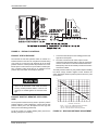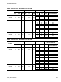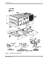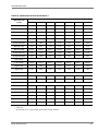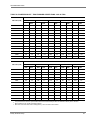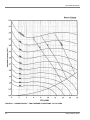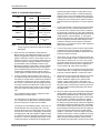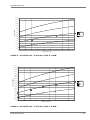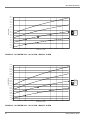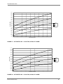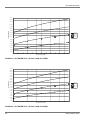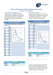
1
INSTALLATION
MANUAL
MILLENNIUM™ ROOFTOP
MODELS:
CONTENTS
NOMENCLATURE . . . . . . . . . . . . . . . . . . . . . . . . . 5
Y12
Y13
Y14
GENERAL . . . . . . . . . . . . . . . . . . . . . . . . . . . . . . . 6
SAFETY CONSIDERATIONS . . . . . . . . . . . . . . . . 6
INSTALLATION . . . . . . . . . . . . . . . . . . . . . . . . . . . 7
GAS HEATING . . . . . . . . . . . . . . . . . . . . . . . . . . . 14
START-UP . . . . . . . . . . . . . . . . . . . . . . . . . . . . . . 61
GAS FURNACE OPERATING INSTRUCTIONS . 67
SEQUENCE OF OPERATION . . . . . . . . . . . . . . . 69
HEAD PRESSURE CONTROL . . . . . . . . . . . . . . 78
SERVICE . . . . . . . . . . . . . . . . . . . . . . . . . . . . . . . 79
MAINTENANCE . . . . . . . . . . . . . . . . . . . . . . . . . . 95
See the following pages for a complete Table of Contents.
NOTES, CAUTIONS AND WARNINGS
Installer should pay particular attention to the words: NOTE,
CAUTION, and WARNING. Notes are intended to clarify or
make the installation easier. Cautions are given to prevent
equipment damage. Warnings are given to alert installer
that personal injury and/or equipment damage may result if
installation procedure is not handled properly.
CAUTION: READ ALL SAFETY GUIDES BEFORE YOU
BEGIN TO INSTALL YOUR UNIT.
SAVE THIS MANUAL
035-16682-000-E-0303
035-16682-000-E-0303
TABLE OF CONTENTS
NOMENCLATURE . . . . . . . . . . . . . . . . . . . . . . . . . . 5
GENERAL . . . . . . . . . . . . . . . . . . . . . . . . . . . . . . . . . 6
SAFETY CONSIDERATIONS . . . . . . . . . . . . . . . . . . 6
SYSTEM SETPOINTS . . . . . . . . . . . . . . . . . . . . . . . . . . 63
NOTES, CAUTIONS AND WARNINGS . . . . . . . . . . . . . . 6
GAS FIRED MODELS . . . . . . . . . . . . . . . . . . . . . . . . . . . . 6
VARIABLE AIR VOLUME (VAV) OR VARIABLE FREQUENCY
DRIVE (VFD) . . . . . . . . . . . . . . . . . . . . . . . . . . . . . . . . . . . . . 64
WHAT TO DO IF YOU SMELL GAS . . . . . . . . . . . . . . . . . . . . . 6
ALL MODELS
INSPECTION
REFERENCE
APPROVALS
. . . . . . . . . . . . . . . . . . . . . . . . . . . . . . . . . .6
. . . . . . . . . . . . . . . . . . . . . . . . . . . . . . . . . .6
. . . . . . . . . . . . . . . . . . . . . . . . . . . . . . . . . .7
. . . . . . . . . . . . . . . . . . . . . . . . . . . . . . . . . .7
INSTALLATION . . . . . . . . . . . . . . . . . . . . . . . . . . . . 7
LIMITATIONS . . . . . . . . . . . . . . . . . . . . . . . . . . . . . . . . . . 7
LOCATION . . . . . . . . . . . . . . . . . . . . . . . . . . . . . . . . . . . . 7
RIGGING AND HANDLING . . . . . . . . . . . . . . . . . . . . . . . 9
CLEARANCES . . . . . . . . . . . . . . . . . . . . . . . . . . . . . . . . 10
DUCTWORK . . . . . . . . . . . . . . . . . . . . . . . . . . . . . . . . . . 11
AIR HOODS FOR FIXED OUTSIDE AIR (W/O ECON . . 11
AIR HOODS FOR ECONOMIZER . . . . . . . . . . . . . . . . . 11
AIR HOODS FOR EXHAUST AIR . . . . . . . . . . . . . . . . . 11
CONDENSATE DRAIN . . . . . . . . . . . . . . . . . . . . . . . . . . 11
SERVICE ACCESS . . . . . . . . . . . . . . . . . . . . . . . . . . . . . 12
COMPRESSORS . . . . . . . . . . . . . . . . . . . . . . . . . . . . . . 12
FILTERS . . . . . . . . . . . . . . . . . . . . . . . . . . . . . . . . . . . . . 12
THERMOSTAT (CONSTANT VOLUME UNITS) . . . . . . 12
SPACE SENSOR (VARIABLE AIR VOLUME UNITS) . . 12
POWER AND CONTROL WIRING . . . . . . . . . . . . . . . . . 13
POWER WIRING DETAIL . . . . . . . . . . . . . . . . . . . . . . . . . . . . 13
GAS HEATING . . . . . . . . . . . . . . . . . . . . . . . . . . . . 14
GAS PIPING . . . . . . . . . . . . . . . . . . . . . . . . . . . . . . . . . . 14
GAS CONNECTION . . . . . . . . . . . . . . . . . . . . . . . . . . . . 14
VENT AND COMBUSTION AIR . . . . . . . . . . . . . . . . . . . 15
233 & 466 MBH HEAT . . . . . . . . . . . . . . . . . . . . . . . . . . . . . . . 15
699 MBH HEAT . . . . . . . . . . . . . . . . . . . . . . . . . . . . . . . . . . . . 15
ELECTRIC HEAT . . . . . . . . . . . . . . . . . . . . . . . . . . . . . . 16
HOT WATER HEAT . . . . . . . . . . . . . . . . . . . . . . . . . . . . 16
. . . . . . . . . . . . . . . . . . 63
CONSTANT VOLUME UNITS (CV) . . . . . . . . . . . . . . . . . . . . 63
GAS FURNACE OPERATING INSTRUCTIONS . . 67
TO LIGHT THE MAIN BURNERS . . . . . . . . . . . . . . . . .
TO SHUT DOWN . . . . . . . . . . . . . . . . . . . . . . . . . . . . . .
POST-START CHECKLIST (GAS) . . . . . . . . . . . . . . . . .
MANIFOLD GAS PRESSURE ADJUSTMENT . . . . . . . .
BURNER INSTRUCTIONS . . . . . . . . . . . . . . . . . . . . . . .
ADJUSTMENT OF TEMPERATURE RISE . . . . . . . . . .
CHECKING GAS INPUT . . . . . . . . . . . . . . . . . . . . . . . .
67
67
67
67
68
68
68
NATURAL GAS . . . . . . . . . . . . . . . . . . . . . . . . . . . . . . . . . . . 68
ELECTRIC HEATING . . . . . . . . . . . . . . . . . . . . . . . . . . . 69
COOLING OPERATING INSTRUCTIONS . . . . . . . . . . . 69
COMPRESSOR . . . . . . . . . . . . . . . . . . . . . . . . . . . . . . . . . . . 69
INTERNAL WIRING . . . . . . . . . . . . . . . . . . . . . . . . . . . . . . . . 69
CONDENSER FANS . . . . . . . . . . . . . . . . . . . . . . . . . . . . . . . 69
SEQUENCE OF OPERATION . . . . . . . . . . . . . . . . 69
CONSTANT VOLUME UNIT . . . . . . . . . . . . . . . . . . . . . 69
OVERVIEW . . . . . . . . . . . . . . . . . . . . . . . . . . . . . . . . . . . . . . 69
THERMOSTAT SEQUENCE . . . . . . . . . . . . . . . . . . . . . . . . . 70
UNIT CONTROLS SEQUENCE . . . . . . . . . . . . . . . . . . . . . . . 70
VARIABLE AIR VOLUME UNIT (VFD & IGV) . . . . . . . . 73
OVERVIEW . . . . . . . . . . . . . . . . . . . . . . . . . . . . . . . . . . . . . . 73
UNIT CONTROLS . . . . . . . . . . . . . . . . . . . . . . . . . . . . . . . . . 74
HEAD PRESSURE CONTROL . . . . . . . . . . . . . . . . 78
DESCRIPTION . . . . . . . . . . . . . . . . . . . . . . . . . . . . . . . . 78
SEQUENCE OF OPERATION - FOR HEAD
PRESSURE CONTROL . . . . . . . . . . . . . . . . . . . . . . . . 79
SERVICE . . . . . . . . . . . . . . . . . . . . . . . . . . . . . . . . . 79
REFRIGERATION SYSTEM . . . . . . . . . . . . . . . . . . . . . 79
COMPRESSORS . . . . . . . . . . . . . . . . . . . . . . . . . . . . . . 79
MOTORS . . . . . . . . . . . . . . . . . . . . . . . . . . . . . . . . . . . . 80
INDOOR BLOWER MOTORS . . . . . . . . . . . . . . . . . . . . . . . . 80
PIPING CONNECTIONS . . . . . . . . . . . . . . . . . . . . . . . . . . . . . 17
POWER EXHAUST OR RETURN AIR FAN MOTORS . . . . . 80
STEAM HEAT . . . . . . . . . . . . . . . . . . . . . . . . . . . . . . . . . 17
CONDENSER FAN MOTORS . . . . . . . . . . . . . . . . . . . . . . . . 80
PIPING CONNECTIONS . . . . . . . . . . . . . . . . . . . . . . . . . . . . . 18
DRAFT MOTOR (GAS FURNACE) . . . . . . . . . . . . . . . . . . . . 80
ECONOMIZER SETPOINT ADJUSTMENT . . . . . . . . . . 18
GAS FURNACE SAFETY FEATURES . . . . . . . . . . . . . . 95
CHECKOUT PROCEDURE . . . . . . . . . . . . . . . . . . . . . . . . . . . 18
COMBUSTION AIR PROVING . . . . . . . . . . . . . . . . . . . . . . . 95
STATIC PRESSURE CONTROL PLASTIC TUBING . . . 18
EXHAUST STATIC PRESSURE . . . . . . . . . . . . . . . . . . . 19
EXHAUST POSITIVE / NEGATIVE STATIC
PRESSURE . . . . . . . . . . . . . . . . . . . . . . . . . . . . . . . . . . 19
START-UP . . . . . . . . . . . . . . . . . . . . . . . . . . . . . . . 61
COMPRESSOR ROTATION . . . . . . . . . . . . . . . . . . . . . . 61
SUPPLY AIR FAN INSTRUCTIONS . . . . . . . . . . . . . . . . 61
ROLLOUT . . . . . . . . . . . . . . . . . . . . . . . . . . . . . . . . . . . . . . . 95
MAINTENANCE . . . . . . . . . . . . . . . . . . . . . . . . . . . 95
NORMAL MAINTENANCE . . . . . . . . . . . . . . . . . . . . . . . 95
FILTERS . . . . . . . . . . . . . . . . . . . . . . . . . . . . . . . . . . . . . . . . . 95
MOTORS . . . . . . . . . . . . . . . . . . . . . . . . . . . . . . . . . . . . . . . . 95
FAN DRIVES . . . . . . . . . . . . . . . . . . . . . . . . . . . . . . . . . . . . . 96
OUTDOOR COIL . . . . . . . . . . . . . . . . . . . . . . . . . . . . . . . . . . 96
CHECK BLOWER BEARING SET SCREWS . . . . . . . . . . . . . 61
GAS BURNER . . . . . . . . . . . . . . . . . . . . . . . . . . . . . . . . 96
CHECKING SUPPLY AIR CFM . . . . . . . . . . . . . . . . . . . . . . . . 61
TO CLEAN BURNERS . . . . . . . . . . . . . . . . . . . . . . . . . . . . . . 96
FAN ROTATION . . . . . . . . . . . . . . . . . . . . . . . . . . . . . . . . . . . 61
COMBUSTION AIR DISCHARGE . . . . . . . . . . . . . . . . . . . . . 96
BELT TENSION . . . . . . . . . . . . . . . . . . . . . . . . . . . . . . . . . . . . 61
AIR BALANCE . . . . . . . . . . . . . . . . . . . . . . . . . . . . . . . . . . . . . 61
CHECKING AIR QUANTITY . . . . . . . . . . . . . . . . . . . . . . . . . . 61
2
SUPPLY AIR DRIVE ADJUSTMENT
CLEANING FLUE PASSAGES AND HEATING ELEMENTS
96
SECURE OWNERS APPROVAL . . . . . . . . . . . . . . . . . . 97
REPLACEMENT PARTS . . . . . . . . . . . . . . . . . . . . . . . . 97
Unitary Products Group
035-16682-000-E-0303
LIST OF FIGURES
Fig. #
1
Pg. #
Fig. #
Pg. #
TYPICAL RIGGING . . . . . . . . . . . . . . . . . . . . . . . . . . . . 8
31 ECONOMIZER RESPONSE EXAMPLE . . . . . . . . . . . 72
2
CENTER OF GRAVITY . . . . . . . . . . . . . . . . . . . . . . . . . 9
32 ECONOMIZER RESPONSE EXAMPLE . . . . . . . . . . . 77
3
RECOMMENDED DRAIN PIPING . . . . . . . . . . . . . . . . 12
33 HOT WATER COIL - 25 & 30T, 1 ROW, AT 10 GPM . 83
4
TYPICAL THERMOSTAT WIRING . . . . . . . . . . . . . . . 12
34 HOT WATER COIL - 25 & 30T, 1 ROW, AT 20 GPM . 83
5
TYPICAL SPACE SENSOR WIRING . . . . . . . . . . . . . 13
35 HOT WATER COIL - 25 & 30T, 1 ROW, AT 30 GPM . 84
6
TYPICAL GAS PIPING CONNECTION . . . . . . . . . . . . 14
36 HOT WATER COIL - 25 & 30T, 1 ROW, AT 40 GPM . 84
7
VENT AND COMBUSTION AIR HOODS . . . . . . . . . . 15
37 HOT WATER COIL - 25 & 30T, 2 ROW, AT 60 GPM . 85
8
669 MBH HEAT VENT . . . . . . . . . . . . . . . . . . . . . . . . . 15
38 HOT WATER COIL - 25 & 30T, 2 ROW, AT 80 GPM . 85
9
FLUE EXTENSION . . . . . . . . . . . . . . . . . . . . . . . . . . . 15
39 HOT WATER COIL - 40 TON, 1 ROW, AT 10 GPM . . 86
10 CLEARANCES . . . . . . . . . . . . . . . . . . . . . . . . . . . . . . . 16
40 HOT WATER COIL - 40 TON, 1 ROW, AT 20 GPM . . 86
11 HOT WATER PIPING CROSS-SECTION . . . . . . . . . . 17
41 HOT WATER COIL - 40 TON, 1 ROW, AT 30 GPM . . 87
12 STEAM PIPING CROSS-SECTION . . . . . . . . . . . . . . 17
42 HOT WATER COIL - 40 TON, 1 ROW, AT 40 GPM . . 87
13 ENTHALPY CONTROLS . . . . . . . . . . . . . . . . . . . . . . . 19
43 HOT WATER COIL - 40 TON, 2 ROW, AT 20 GPM . . 88
14 DRY BULB SETPOINT ADJUSTMENT . . . . . . . . . . . . 19
44 HOT WATER COIL - 40 TON, 2 ROW, AT 40 GPM . . 88
15 SINGLE ENTHALPY SETPOINT ADJUSTMENT . . . . 20
45 HOT WATER COIL - 40 TON, 2 ROW, AT 60 GPM . . 89
16 BOTTOM SUPPLY AND RETURN . . . . . . . . . . . . . . . 39
46 HOT WATER COIL - 40 TON, 2 ROW, AT 80 GPM . . 89
17 END RETURN, BOTTOM SUPPLY . . . . . . . . . . . . . . . 40
47 STEAM COIL - 25 & 30 TON (1 ROW) . . . . . . . . . . . . 90
18 BOTTOM RETURN, FRONT & REAR SUPPLY . . . . . 41
48 STEAM COIL - 40 TON (1 ROW) . . . . . . . . . . . . . . . . 90
19 END RETURN, FRONT & REAR SUPPLY . . . . . . . . . 42
49 TYPICAL WIRING FOR VAV UNIT WITH GAS HEAT. 91
20 FIELD INSTALLED DISCONNECT . . . . . . . . . . . . . . . 43
50 LEGEND FOR VAV UNITS . . . . . . . . . . . . . . . . . . . . . 92
21 PARTIAL ROOF CURB MODEL 1RC0455P . . . . . . . . 44
51 TYPICAL WIRING FOR CV UNIT WITH GAS HEAT. . 93
22 FULL ROOF CURB MODEL 1RC0455F . . . . . . . . . . . 45
52 LEGEND FOR CV UNIT . . . . . . . . . . . . . . . . . . . . . . . 94
23 FAN PERFORMANCE - 25 TON . . . . . . . . . . . . . . . . . 48
53 TYPICAL FLUE BAFFLE . . . . . . . . . . . . . . . . . . . . . . . 97
24 FAN PERFORMANCE - 30 TON . . . . . . . . . . . . . . . . . 51
54 COMPONENT LOCATION . . . . . . . . . . . . . . . . . . . . . 98
25 FAN PERFORMANCE - 40 TON . . . . . . . . . . . . . . . . . 54
55 25 TON CHARGING CURVE . . . . . . . . . . . . . . . . . . . 99
26 PWR EXHAUST - 1 FWD CURVE FAN - 25T . . . . . . . 58
56 30 TON CHARGING CURVE . . . . . . . . . . . . . . . . . . 100
27 PWR EXHAUST - 2 FWD CURVED FANS - 30 & 40T. 60
57 40 TON CHARGING CURVE . . . . . . . . . . . . . . . . . . 101
28 BELT TENSION ADJUSTMENT . . . . . . . . . . . . . . . . . 61
58 PRESS. DROP DRY COIL VS SPLY AIR 25T. . . . . . 102
29 TYPICAL GAS VALVE . . . . . . . . . . . . . . . . . . . . . . . . . 68
59 PRESS. DROP DRY COIL VS SPLY AIR 30/40T . . . 103
30 TYPICAL FLAME APPEARANCE . . . . . . . . . . . . . . . . 69
Unitary Products Group
3
035-16682-000-E-0303
LIST OF TABLES
Tbl. #
Pg. #
1
COOLING & ELECTRICAL APPLICATION . . . . . . . . . . 7
2
COOLING & ELEC. APP. LIMITATIONS . . . . . . . . . . . . 7
3
GAS APPLICATION DATA . . . . . . . . . . . . . . . . . . . . . . 8
4
UNIT WEIGHTS . . . . . . . . . . . . . . . . . . . . . . . . . . . . . . . 9
5
UNIT CORNERWEIGHT . . . . . . . . . . . . . . . . . . . . . . . 10
6
UNIT CENTER OF GRAVITY . . . . . . . . . . . . . . . . . . . 10
7
CONTROL WIRE SIZES . . . . . . . . . . . . . . . . . . . . . . . 12
8
PIPE SIZES . . . . . . . . . . . . . . . . . . . . . . . . . . . . . . . . . 14
9
GENERAL PHYSICAL DATA . . . . . . . . . . . . . . . . . . . . 21
10 REFIGERANT CHARGE . . . . . . . . . . . . . . . . . . . . . . . 22
11 ELECTRICAL DATA BASIC UNIT - 25 TON . . . . . . . . 22
12 ELECTRICAL DATA BASIC UNIT - 30 TON . . . . . . . . 23
13 ELECTRICAL DATA BASIC UNIT - 40 TON . . . . . . . . 23
Tbl. #
Pg. #
29 POWER EXHAUST - ONE FORWARD CURVED
FAN 25 TON . . . . . . . . . . . . . . . . . . . . . . . . . . . . . . . . 57
30 POWER EXHAUST - TWO FORWARD CURVED
FANS - 30 & 40 TON . . . . . . . . . . . . . . . . . . . . . . . . . . 59
31 BELT ADJUSTMENT . . . . . . . . . . . . . . . . . . . . . . . . . . 62
32 BLOWER SPEED RATE OF CHANGE . . . . . . . . . . . . 63
33 SUMMARY OF FIELD AND FACTORY SETPOINTS . 64
34 25 TON DRIVE ADJUSTMENT . . . . . . . . . . . . . . . . . . 65
35 30 TON DRIVE ADJUSTMENT . . . . . . . . . . . . . . . . . . 65
36 40 TON DRIVE ADJUSTMENT . . . . . . . . . . . . . . . . . . 66
37 DRIVE ADJUSTMENT FOR POWER EXHAUST 25 TON . . . . . . . . . . . . . . . . . . . . . . . . . . . . . . . . . . . . 66
38 DRIVE ADJUSTMENT FOR POWER EXHAUST 30 & 40 TON . . . . . . . . . . . . . . . . . . . . . . . . . . . . . . . . 67
14 ELECTRICAL DATA BASIC UNIT WITH ELECTRIC
HEAT - 25 TON . . . . . . . . . . . . . . . . . . . . . . . . . . . . . . 24
39 GAS RATE - CUBIC FEET PER HOUR . . . . . . . . . . . 68
15 ELECTRICAL DATA BASIC UNIT WITH ELECTRIC
HEAT - 30 TON . . . . . . . . . . . . . . . . . . . . . . . . . . . . . . 25
41 COOLING STAGE RELAYS . . . . . . . . . . . . . . . . . . . . 75
16 ELECTRICAL DATA BASIC UNIT WITH ELECTRIC
HEAT - 40 TON . . . . . . . . . . . . . . . . . . . . . . . . . . . . . . 26
43 STEAM COIL (1 ROW, 25 & 30 TON) . . . . . . . . . . . . . 80
40 COOLING STAGE RELAYS . . . . . . . . . . . . . . . . . . . . 71
42 SYSTEM MOISTURE INDICATOR . . . . . . . . . . . . . . . 78
17 ELECTRICAL DATA BASIC UNIT WITH POWER
EXHAUST - 25 TON . . . . . . . . . . . . . . . . . . . . . . . . . . . 27
44 STEAM COIL (1 ROW, 40 TON) . . . . . . . . . . . . . . . . . 80
18 ELECTRICAL DATA BASIC UNIT WITH POWER
EXHAUST - 30 TON . . . . . . . . . . . . . . . . . . . . . . . . . . . 28
46 STATIC RESISTANCE STEAM COIL (40 TON) . . . . . 80
19 ELECTRICAL DATA BASIC UNIT WITH POWER
EXHAUST - 40 TON . . . . . . . . . . . . . . . . . . . . . . . . . . . 29
48 HOT WATER COIL (1 ROW, 40 TON) . . . . . . . . . . . . 81
20 ELECTRICAL DATA BASIC UNIT WITH POWER
EXHAUST & ELECTRIC HEAT - 25 TON . . . . . . . . . . 30
21 ELECTRICAL DATA BASIC UNIT WITH POWER
EXHAUST & ELECTRIC HEAT - 30 TON . . . . . . . . . . 33
45 STATIC RESISTANCE STEAM COIL (25 & 30 TON) . 80
47 HOT WATER COIL (1 ROW 25 & 30 TON) . . . . . . . . . 81
49 WATER PRESSURE DROP (1 ROW,
25 & 30 TON) . . . . . . . . . . . . . . . . . . . . . . . . . . . . . . . . 82
50 WATER PRESSURE DROP (1 ROW, 40 TONS) . . . . 82
51 HOT WATER COIL (2 ROW, 25 & 30 TON) . . . . . . . . 82
22 ELECTRICAL DATA BASIC UNIT WITH POWER
EXHAUST & ELECTRIC HEAT - 40 TON . . . . . . . . . . 36
52 WATER PRESSURE DROP (2 ROW,
25 & 30 TON) . . . . . . . . . . . . . . . . . . . . . . . . . . . . . . . . 82
23 FAN PERFORMANCE - 25 TON
. . . . . . . . . . . . . . . . 46
53 WATER PRESSURE DROP (2 ROW, 40 TON) . . . . . 82
24 FAN PERFORMANCE - 30 TON
. . . . . . . . . . . . . . . . 49
25 FAN PERFORMANCE - 40 TON
. . . . . . . . . . . . . . . . 52
54 STATIC RESISTANCE HOT WATER COIL
(25 & 30 TON) . . . . . . . . . . . . . . . . . . . . . . . . . . . . . . . 82
26 COMPONENT STATIC RESISTANCE . . . . . . . . . . . . 55
27 SUPPLY FAN MOTOR AND DRIVE DATA . . . . . . . . . 56
28 EXHAUST FAN DRIVE DATA . . . . . . . . . . . . . . . . . . . 56
4
55 STATIC RESISTANCE HOT WATER COIL
(40 TON) . . . . . . . . . . . . . . . . . . . . . . . . . . . . . . . . . . . 82
56 INDOOR BLOWER BEARING LUBRICATION
SCHEDULE . . . . . . . . . . . . . . . . . . . . . . . . . . . . . . . . . 96
Unitary Products Group
Unitary Products Group
1 - BOTTOM RETURN
2 - BOTTOM SUPPLY
3 - END RETURN
4 - REAR SUPPLY
5 - FRONT SUPPLY
0 (ZER0) NO HEAT
C
X
1- 1 ROW
W 1 - 1 ROW
2 - 2 ROW
4 - 40 KW
8 - 80 KW
1 - 108 KW (1)
E
N/S 2 - 233 MBH
4 - 466 MBH
7 - 700 MBH (40T ONLY)
5 - FC
6 - AF
1 - CV
(5)
2 - VAV (IGV)
3 - VAV (VFD-CUSTOMER)
4 - VAV (VFD -FACTORY
INSTALLED)
9 - BY-PASS VFD
Q - 9,5,7
R - 9,5,8
S - 9,6,7
T - 9,6,8
M - 4,5,7 7 - 1” DEFLECTOR
N - 4,5,8 8 - 2” DEFLECTOR
O - 4,6,7
P - 4,6,8
I - 3,5,7
J - 3,5,8
K - 3,6,7
L - 3,6,8
E - 2,5,7
F - 2,5,8
G - 2,6,7
H - 2,6,8
A - 1,5,7
B - 1,6,7
C - 1,5,8
D - 1,6,8
2 - 208/230-60
3 - 380-60
4 - 460-60
5 - 575 - 60
7 - 380/415-50
A - STANDARD
B - 65%
C - 95%
D - 2” HI EFF
A - 1,3,5,7
B - 2,3,5,7
C - 1,4,5,7
D - 2,4,5,7
E - 1,3,6,7
F - 2,3,6,7
G -1,4,6,7
H - 2,4,6,7
I - 1,3,5,8
J - 2,3,5,8
K -1,4,5,8
L - 2,4,5,8
M -1,3,6,8
N - 2,3,6,8
O -1,4,6,8
P - 2,4,6,8
Q - 1,3,9,7
3 - 7.5 HP
4 - 10 HP
5 - 15 HP
6 - 7.5 HP HI EFF
7 - 10 HP HI EFF
8 - 15 HP HI EFF
9 - 5 HP (25T ONLY)
0 - 5 HP HI IFF (25 T ONLY)
1 - MODULATING
2 - NON-MODULATING
A - W / VFD
1 - 10 HP STD (2)
2 - 15 HP STD
3 - 20 HP STD
4 - 25 HP STD
5 - 10 HP HI-EFF
6 - 15 HP HI-EFF
7 - 20 HP HI-EFF
8 - 25 HP HI-EFF
9 - 7.5 HP STD (25T ONLY)
0 - 7.5 HP HI-EFF (25T ONLY)
A - BAROMETRIC
B - 1,3
C - 1,4
D - 1,5
E - 1,6
F - 1,7
G - 1,8
H - 2,3
I - 2,4
J - 2,5
K - 2,6
L - 2,7
M - 2,8
N - NONE
O - 1,9
P - 1,0
Q - 2,9
R - 2,0
S - A,3
T - A,4
U - A,5
V - A,6
W - A,7
X - A,8
Z - A,0
1. HEAT CAPACITY 108K NOT AVAILABLE W208/230V ONL Y.
2. THE STANDARD EFFICIENCY MOTOR MEETS CANADIAN MINIMUM
EFFICIENCY REGULATIONS AS MANDATED IN THE CANADIAN ENERGY
EFFICIENCY REGULATIONS. HIGHER OR “ULTRA HIGH” EFFICIENCY
MOTORS ARE NOT AVAILABLE FOR 575V.
3. (VFD-CUSTOMER) - WIRED FOR VFD ONLY, VFD WILL BE CUSTOMER
SUPPLIED AND FIELD INSTALLED.
4. CV ONLY W/HEAD PRESSURE CONTROL ON REHEAT COIL.
5. MUST HAVE HOT GAS BY-PASS W/VAV
6. GAS HEAT NOT AVAILABLE IN FRONT SUPPLY CONFIGURATION.
HOT WATER, STEAM AND ELECTRIC HEAT ONLY AVAILABLE IN BOTTOM SUPPLY CONFIGURATION
7. POWER EXHAUST AND BAROMETRIC RELIEF NOT AVAILABLE IN END RETURN CONFIGURATION.
NOTES:
N - NATURAL GAS
S - NATURAL GAS, SS HEAT EXCHANGER
E - ELECTRIC HEAT
C - COOLING ONLY
W - HOT WATER COIL
X - STEAM COIL
FRONT SUPPLY - COOLING ONLY
ELECTRIC HEAT - BOTTOM SUPPLY
GAS HEAT - BOTTOM OR REAR SUPPLY
A - 1,2
B - 1,4
C - 1,5
D - 3,2
E - 3,4
F - 3,5
2 - 25 TON
3 - 30 TON
4 - 40 TON
Y
R - 2,3,9,7
S - 1,4,9,7
T - 2,4,9,7
U - 1,3,0,7
V - 2,3,0,7
W - 1,4,0,7
X - 2,4,0,7
Y - 1,3,9,8
Z - 2,3,9,8
1 - 1,4,9,8
2 - 2,4,9,8
3 - 1,3,0,8
4 - 2,3,0,8
5 - 1,4,0,8
6 - 2,4,0,8
7 - YES
8 - NO
HEAD PRESS. CTL
5 - STANDARD
6 - HI-CAP (30-40T)
9 - STD COIL W/TC
0 - HI-CAP COIL W/TC
(5)
3 - STANDARD
4 - HOT GAS BY-PASS
1 - STANDARD
2 - TECHNICOAT
A - DUAL ENTH
B - SINGLE ENTH
C - DRY BULB
D - MANUAL
E - NONE
A - STD CONTROL, NO DISCONNECT,
NO OUTLET
B - STD CONTROL, W/DISC & 110V
OUTLET
C - STD CONTROL, W/DISC,
NO OUTLET
D - SYNTHESYS CONTROL WITHOUT
DISCONNECT OR CONVENIENCE
OUTLET
E - SYNTHESYS CONTROL WITH
DISCONNECT AND CONVENIENCE
OUTLET
F - SYNTHESYS CONTROL WITH
DISCONNECT ONLY
035-16682-000-E-0303
NOMENCLATURE
5
035-16682-000-E-0303
GENERAL
YORK Model Y12/Y13/Y14 units are single package cooling
only or cooling with gas, electric, hot water or steam heating
designed for outdoor installation on a rooftop and for non-residential use.
The units are completely assembled on rigid, permanently
attached base rails. All piping, refrigerant charge, and electrical wiring is factory installed and tested. The units require
electric power, gas, steam, or hot water connections and duct
connections. Gas fired units also require installation of a flue
gas outlet hood.
SAFETY CONSIDERATIONS
NOTES, CAUTIONS AND WARNINGS
Installer should pay particular attention to the words: NOTE,
CAUTION, and WARNING. Notes are intended to clarify or
make the installation easier. Cautions are given to prevent
equipment damage. Warnings are given to alert installer that
personal injury and/or equipment damage may result if installation procedure is not handled properly.
GAS FIRED MODELS
This Furnace is not to be used for temporary heating of buildings or structures under construction.
ALL MODELS
Installation and servicing of air conditioning equipment can
be hazardous due to system pressure and electrical components. Only trained and qualified service personnel should
install, repair or service air conditioning equipment.
Untrained personnel can perform basic maintenance functions of cleaning coils and filters and replacing filters. All other
operations should be performed by trained service personnel.
When working on air conditioning equipment, observe precautions in the literature, tags and labels attached to the unit
and other safety precautions that may apply.
Follow all safety codes, including ANSI Z223.1-Latest Edition: wear safety glasses and work gloves; use quenching
cloth for unbrazing operations; have fire extinguisher available for all brazing operations.
DO NOT store or use gasoline or other flammable vapors and
liquids in the vicinity of this or any other appliance.
WHAT TO DO IF YOU SMELL GAS
Do not try to light any appliance. Do not touch any electrical
switch. Do not use any phone in your building. Immediately
call your gas supplier from a neighbor’s phone. Follow the
gas supplier’s instructions. If you cannot reach your gas supplier, call the fire department.
The furnace and its individual shut-off valve must
be disconnected from the gas supply piping system during any pressure testing of that system at
test pressures in excess of 0.5 psig. Pressures
greater than 0.5 will cause gas valve damage
resulting in a hazardous condition. If gas valve is
subjected to a pressure greater than 0.5 psig, it
must be replaced. The furnace must be isolated
from the gas supply piping system by closing its
individual manual shut-off valve during any pressure testing of that system at test pressures equal
to or less than 0.5 psig.
6
Before performing service or maintenance operations on unit, turn off main power switch to unit.
Electrical shock could cause personal injury.
Improper installation, adjustment, alteration, service or maintenance can cause injury or property
damage. Refer to this manual. For assistance or
additional information consult a qualified installer,
service agency or the gas supplier.
INSPECTION
As soon as a unit is received, it should be inspected for possible damage during transit. If damage is evident, the extent of
damage should be noted on the carrier’s freight bill. A separate request for inspection by the carrier’s agent should be
made in writing.
Unitary Products Group
035-16682-000-E-0303
REFERENCE
Additional information is available in the following reference
forms:
•
•
530.70-TG1Y - Technical Guide
530.70-RP1Y - Unit Replacement Parts List (25, 30 & 40
Tons)
If components are to be added to a unit to meet local codes,
they are to be installed at the contractor's and/or the customer's expense.
Size of unit for proposed installation should be based on heat
loss / heat gain calculation made according to the methods of
the Air Conditioning Contractors of America (ACCA).
LOCATION
All forms referenced in this instruction may be ordered from
Standard Register
2101 West Tecumseh Road
Norman, Oklahoma 73069
Toll Free Fax: (877) 379-7920
Toll Free Phone: (877) 318-9675
Use the following guidelines to select a suitable location for
these units:
TABLE 1: COOLING & ELECTRICAL APPLICATION
UNIT POWER
SUPPLY
APPROVALS
Designed certified by CGA, ETL, CETL as follows:
1.
For use as a forced air furnace with cooling unit (gas
heat models).
2.
For outdoor installation only.
3.
For installation on combustible material and may be
installed directly on combustible flooring or Class A,
Class B or Class C roof covering materials.
4.
For use with natural gas (convertible to LP with kit).
MIN. VOLTS
MAX VOLTS
575-3-60
540
630
208/230-3-60
187
252
460-3-60
432
504
TABLE 2: COOLING & ELEC. APP. LIMITATIONS
MODEL
LIMITATIONS
Y12
Y13
Y14
Supply Air CFM
(min./max)
6,00012,5000
6,00015,000
8,00020,000
Entering Wet Bulb
Temp (F°) (min./max)
57/75
57/75
57/75
Ambient Temp
40/120
40/120
40/120
Not suitable for use with conventional venting systems.
INSTALLATION
LIMITATIONS
The installation of this unit must conform to local building
codes, or in the absence of local codes, with ANSI Z223.1
Natural Fuel Gas Code and /or CAN/CGA B149 installation
codes.
Min. Air Temperature on Gas Fired Heat Exchangers (°F)
In U.S.A.:
1.
National Electrical Code ANSI/NFPA No. 70-Latest Edition.
2.
National Fuel Gas Code Z223.1-Latest Edition.
3.
Gas-Fired Central Furnace Standard ANSI Z21.47-Latest Edition.
4.
Local gas utility requirements.
VOLTAGE VARIATIONS
Aluminized
25
25
25
Stainless
0
0
0
1.
Unit is designed for outdoor installation only.
2.
Condenser coils must have an unlimited supply of air.
Where a choice of location is possible, position the unit
on either north or east side of building.
3.
Suitable for roof mount on curb.
Refer to Table 1 for Cooling and Electrical Application Data
and to Table 2 for Gas Heat Application Data.
4.
Roof structures must be able to support the weight of the
unit and its accessories. Unit must be installed on a solid
level roof curb or appropriate angle iron frame.
After installation, gas fired units must be adjusted to obtain a
temperature rise within the range specified on the unit rating
plate.
5.
Maintain level tolerance to 3/4 inches across width and 2
inches along length.
Unitary Products Group
7
035-16682-000-E-0303
TABLE 3: GAS APPLICATION DATA
INPUT CAPACITY (MBH)
0 TO 2,000 FEET ABOVE
SEA LEVEL
3,000 FEET ABOVE
4,000 FEET ABOVE
SEA LEVEL4
SEA LEVEL4
AVAILABLE
ON
MODELS
MAX.
MIN.
MAX.
MIN.
MAX.
MIN.
233
233
205
205
196
196
Y12, Y13,
Y14
466
233
410
205
392
196
6995
233
615
205
587
196
TEMP. RISE °F
GAS
AT FULL INPUT2 3
RATE1
(FT.3/HR.)
MIN.
MAX.
217
5
35
Y12, Y13,
Y14
434
15
45
Y14
650
20
50
1.
Based on maximum input and 1075 Btu/Ft.3
2.
The air flow must be adjusted to obtain a temperature rise within the range shown.
3.
On VAV units, individual room damper boxes must go full open in heating mode to ensure airflow falls within temperature rise
range.
4.
For operation at elevations above 2,000 feet and, in the absence of specific recommendations from local authority having jurisdiction, equipment ratings shall be reduced at the rate of 4% for each 1,000 feet above sea level.
5.
Minimum heating CFM for 699 MBH input heat is 11,700 CFM.
If a unit is to be installed on a roof curb other than
a YORK roof curb, gasketing must be applied to all
surfaces that come in contact with the unit underside.
If a unit is to be installed on an angle iron frame it
is recommended that it be sized to allow the bottom rail to overhang to facilitate installation of condensate drains (see Fig. 3).
6.
Maintain level tolerance to 3/4 inches across width and 2
inches along length.
FIGURE 1 -
8
TYPICAL RIGGING
Unitary Products Group
035-16682-000-E-0303
TABLE 4: UNIT WEIGHTS
COMPONENT
Basic
Unit1
40KW
80KW
108KW
Hot Water Coil 1
Row
Hot Water Coil 2
Row
7.5hp
10hp
15hp
20hp
25hp
Inlet Guide Vanes
w/ Actuator
30 TON
40 TON
4,300
4,600
5,100
Gas Heat
90
90
180
180
270
270
Electric Heat
75
75
90
90
100
100
Hot Water Heat
233 MBH
466 MBH
699 MBH
Steam Coil 1 Row
25 TON
75
90
100
71 lbs.
71 lbs
90
90 lbs.
90 lbs.
0/10
50/90
85/110
165/200
175
205
VFD2
24 lbs.
24 lbs.
24 lbs.
VFD w/Bypass2
28 lbs.
28 lbs.
28 lbs.
Barometric
Powered
A
240"
LEFTT SIDE
CENTER OF GRAVITY1
Refer to Tables 5 and 6 for A, B, C, D and X and Y data
respectively
All panels must be secured in place when the unit
is lifted.
The condenser coils should be protected from
damage by the rigging cables with plywood or
other suitable material.
An adhesive backed cover is provided over the
outside of the combustion air inlet opening on gas
fired units to prevent moisture from entering the
unit which could cause damage to electrical components. Allow this closure label to remain in place
until the combustion air hood is to be installed
(Refer to Figures 7, 8, & 9).
75
325
100/110
110/120
160/200
1.
Weight includes the 10HP motor and economizer.
2.
Weight for 20-25HP drive.
Unitary Products Group
X
Y
1.
CON
DE NSER
COILEND
D
83"
FIGURE 2 -
BACK
87 lbs.
175
Exhaust
40
75
180
325
Exhaust Motor (Std./Hi-eff)
5hp
75/90
7.5hp
100/110
100/110
10hp
110/120
110/120
15hp
160/200
Low Ambient Head Pressure Control
208/203V,460V &
10
10
380-3-50Hz
575V &
40
40
380-3-60 Hz
Filters
6" Rigid
80
80
Refrigeration
Hi Capacity Coil
N/A
45
Coated Cond. Coil
32
30
Hot Gas Bypass
20
20
Disconnect
Convenience
40/40
40/40
Outlet
Accessories
Partial Curb
385
385
Full Curb
545
545
C
B
90
180
270
71
Steam Heat
87 lbs.
87 lbs.
Blower Motor (Std./Hi-eff)
0/10
10/20
0/10
60/100
50/90
105/110
95/100
165/200
CENTERO
F
GRAVITY
RIGHT SIDE
10
40
80
RIGGING AND HANDLING
This unit is not designed to be handled with a fork-truck
Exercise care when moving the unit. Do not remove any
packaging until the unit is near the place of installation. Rig
the unit by attaching chain or cable slings to the holes provided in lifting lugs. Spreaders MUST be used across the top
of the unit. Refer to Figure 1.
25
40
20
•
40/40
•
•
Rig with six cables and spread with four 95-inch spreaders across width and two spreaders of length equal to A
+ B.
Refer to Tables 4 and 5 for unit weight.
Center of gravity includes economizer, exhaust or return
air fan and inlet guide vanes (Refer to Table 6).
385
545
9
035-16682-000-E-0303
TABLE 5: UNIT CORNERWEIGHT
25 TON
30 TON
40 TON
UNIT
DESCRIPTION
A
B
C
D
A
B
C
D
A
B
C
D
Basic Unit
988
988
1162
1162
1011
987
1189
1213
1088
1088
1363
1363
Basic Unit With
Economizer
1058
1058
1192
1192
1106
1080
1194
1220
1153
1153
1398
1398
Basic Unit With
Economizer
and Gas or
Electric Heat
1107
1107
1232
1232
1131
1080
1259
1310
1203
1173
1437
1467
Basic Unit With
Economizer
and Gas or
Electric Heat
and Power
Exhaust
1261
1261
1272
1272
1262
1206
1290
1346
1347
1317
1457
1487
CLEARANCES
TABLE 6: UNIT CENTER OF GRAVITY
25 TON
30 TON
40 TON
X
Y
X
Y
X
Y
Basic Unit
99”
46”
98”
45”
93”
46"
Basic Unit With
Econ.
110”
46”
108”
45”
97”
46"
Basic Unit With
Econ. & Gas or
Elect. Heat,
Steam or Hot
Water Heat
104”
45”
102”
44”
96”
45"
Basic Unit With
Econ. & Gas or
Elect. Heat, &
Power Exhaust
118”
MODEL
10
45”
112”
44”
108”
45"
All units require certain clearances for proper operation and
service. Installer must make provisions for adequate combustion and ventilation air in accordance with section 5.3, Air for
Combustion and Ventilation of the National Fuel Gas Code
ANSI Z223.1 or Sections 7.2, 7.3 or 7.4 of CAN/CGA B149
installation codes-Latest Edition and/or applicable provisions
of the local building codes. Refer to Figure 10 for clearances
required for combustible construction, servicing, and proper
unit operation.
(COOLING OPERATION) Do not permit overhanging structures or shrubs to obstruct condenser air
discharge outlet, combustion air inlet or vent outlets.
Unitary Products Group
035-16682-000-E-0303
When the unit is equipped with power exhaust fans or return
air fan the return duct should have a 90 elbow before opening
to the building space to abate noise.
(GAS HEATING OPERATION)
Excessive exposure to contaminated combustion
air will result in safety and performance related
problems. To maintain combustion air quality, the
recommended source of combustion air is the outdoor air supply.
The outdoor air supplied for combustion should be
free from contaminants due to chemical exposure
that may be present from the following sources:
•
•
•
•
•
Commercial buildings
Indoor pools
Laundry rooms
Hobby or craft rooms
Chemical storage areas
The following substances should be avoided to
maintain outdoor combustion air quality:
•
•
•
•
•
•
•
•
•
•
•
•
•
Permanent wave solutions
Chlorinated waxes and cleaners
Chlorine based swimming pool cleaners
Water softening chemicals
De-icing salts or chemicals
Carbon tetrachloride
Halogen type refrigerants
Cleaning solvents (such as perchloroethylene)
Printing inks, paint removers, varnishes, etc.
Hydrochloric acid
Cements and glues
Antistatic fabric softeners for clothes dryers
Masonry acid washing materials
The supply and return air duct systems should be designed
for the CFM and static pressure requirements of the job. They
should NOT be sized to match the dimensions of the duct
connections on the unit.
If the unit is equipped with hot water or steam heat then the
supply air direction will be down only.
AIR HOODS FOR FIXED OUTSIDE AIR
(UNITS WITHOUT ECONOMIZER)
These hoods are factory installed. The dampers may be
adjusted by loosening the thumb screw, turning the lever to
the desired position, and retightening the thumb screw.
AIR HOODS FOR ECONOMIZER
There are (3) economizer outside air intake hoods provided
with the unit. The hood on the end of the unit is factory
mounted. The (2) front and rear hoods are made operational
per the following instructions.
Remove the screws holding the economizer hood shipping
covers in place. Discard covers.
Rotate the hoods out (each hood is hinged in the lower corner). Secure the hoods with screws along the top and sides.
Apply a bead of RTV sealer along the edge of both hoods
and each pivot joint to prevent water leakage.
Seal any unused screw holes with RTV or by replacing the
screw.
AIR HOODS FOR EXHAUST AIR
When furnished, these hoods and dampers are factory
installed.
DUCTWORK
CONDENSATE DRAIN
Ductwork should be designed and sized according to the
methods in Manual Q of the Air Conditioning Contractors of
America (ACCA).
A closed return duct system should be used. This will not preclude use of economizers or outdoor fresh air intake. The
supply and return air duct connections at the unit should be
made with flexible joints to minimize noise.
Unitary Products Group
There is one condensate drain connection. Trap the connection per Figure 3. The trap and drain lines should be protected from freezing.
Plumbing must conform to local codes. Use a sealing compound on male pipe threads. Install condensate drain lines
from the 1-1/2 inch NPT female connections on the unit to an
open drain.
11
035-16682-000-E-0303
FILTERS
U N IT B A S E
D R A IN C O N N E C T IO N
F A C T O R Y IN S T A L L E D
Y
R O
C U
O
P E R IM
S U P P
S T R U C
R
O F
R B
E T E R
O R T
T U R E
Throwaway or rigid filters are supplied with each unit. Filters
must always be installed ahead of evaporator coil and must
be kept clean or replaced with same size and type. Dirty filters will reduce the capacity of the unit and will result in
frosted coils or safety shutdown. Required filter sizes are
shown in Table 9. The unit should not be operated without filters properly installed.
H
F IE L D S U P P L IE D
Y - M IN IM U M 2 "
H - 1 /2 " P L U S T O T A L S T A T IC P R E S S U R E - M IN IM U M
FIGURE 3 -
RECOMMENDED DRAIN PIPING
THERMOSTAT (CONSTANT VOLUME UNITS)
T 7 3 0 0 T H E R M O S T A T S U B B A S E
R C
G
Y 1
Y 2
Y 3
Y 4
W 1
W 2
A 1
C
T
T
R E M O T E
S E N S O R
SERVICE ACCESS
2 T H O 4 7 0 2 2 2 4
R
G
Access to all serviceable components is provided by the following hinged doors:
E Q U IP . G N D .
Y 1
L 1
Y 2
Y 3
•
Furnace compartment
•
Supply Air Fan compartment Evaporator Coil compartment (three doors)
•
Filter compartment economizer compartment (two doors)
•
Power Exhaust compartment (two doors)
•
Main control panels (one door)
Refer to Figure 54 for location of these access panels.
Make sure that all screws and panel latches are
replaced and properly positioned on the unit to
maintain an air-tight seal.
COMPRESSORS
Units are shipped with compressor mountings factoryadjusted and ready for operation.
DO NOT loosen compressor mounting bolts.
12
L 2
L 3
T B 1
A
B
C
Y 4
W 1
P O W E R S U P P L Y
W 2
A 1
P O W E R
C
FIGURE 4 -
W IR IN G
TYPICAL THERMOSTAT WIRING
The thermostat, if used, should be located on an inside wall
approximately 56 inches above the floor where it will not be
subject to drafts, sun exposure or heat from electrical fixtures
or appliances. Follow manufacturer's instructions enclosed
with sensor for general installation procedure (See Figure 4).
Refer to Table 7 for control wire sizing and maximum length.
TABLE 7: CONTROL WIRE SIZES
WIRE SIZE
MAXIMUM LENGTH
20 AWG
100 Feet
18 AWG
150 Feet
SPACE SENSOR (VARIABLE AIR VOLUME UNITS)
The space sensor, if used, should be located on an inside
wall approximately 56 inch above the floor where it will not be
subject to drafts, sun exposure or heat from electrical fixtures
or appliances. Follow manufacturer's instructions enclosed
with sensor for general installation procedure (See Figure 5).
Unitary Products Group
035-16682-000-E-0303
C M -V A V
Y E L
7
R P
Y E L
T
S R S
T
6
L E G E N D
R P
S R S
M O U N T E D IN
C O N T R O L B O X
FIGURE 5 -
M A N U A L P O T E N T IO M E T E R
S P A C E R E S E T S E N S O R
NOTE: Since not all local codes allow the mounting of a disconnect on the unit, please confirm compliance with
local code before mounting a disconnect on the unit.
Electrical wiring must be sized properly to carry the load.
Each unit must be wired with a separate branch circuit fed
directly from the meter panel and properly fused.
TYPICAL SPACE SENSOR WIRING
POWER AND CONTROL WIRING
Field wiring to the unit must conform to provisions of National
Electrical Code (NEC) ANSI / NFPA 70-Latest Edition and / or
local ordinances. The unit must be electrically grounded in
accordance with the NEC and / or local codes. Voltage tolerances which must be maintained at the compressor terminals
during starting and running conditions are indicated on the
unit Rating Plate and Table 1.
The internal wiring harnesses furnished with this unit are an
integral part of the design certified unit. Field alteration to
comply with electrical codes should not be required. If any of
the wire supplied with the unit must be replaced, replacement
wire must be of the type shown on the wiring diagram and the
same minimum gauge as the replaced wire.
Power supply to the unit must be NEC Class 1 and must
comply with all applicable codes. A disconnect switch must
be provided (factory option available). The switch must be
separate from all other circuits. Wire entry at knockout openings requires conduit fittings to comply with NEC and/or Local
Codes. Refer to Figures 16, 17, 18, and 19 for installation
location of openings.
If installing a field mounted disconnect on the unit, refer to
Figure 20 for the recommended mounting location. UnitstrutTM or equivalent rails should be mounted as shown to
provide structure for mounting. The location of the rails
should be adjusted to fit the disconnect within the dimensions
shown. Conduit run from the disconnect to the power entry
location in the baserail should be routed so that it does not
interfere with the doors of the unit access panels.
When connecting electrical power and control wiring to the unit, waterproof connectors MUST BE
USED so that water or moisture cannot be drawn
into the unit during normal operation. The above
waterproofing conditions will also apply when
installing a field-supplied disconnect switch.
Refer to Figure 4 and 5 for typical field wiring and to the
appropriate unit wiring diagram mounted inside control doors
for control circuit and power wiring information.
POWER WIRING DETAIL
Units are factory wired for the voltage shown on the unit
nameplate. The main power block requires copper wires.
Refer to Electrical Data Tables 11 through 22 to size power
wiring, fuses and disconnect switch. All field supplied wiring,
fuses and disconnects must comply with applicable NEC
codes.
Power wiring is brought into the unit through the side of the
baserail or the bottom of the unit/control box inside the curb.
The baserail has a 2-1/2” diameter hole for field wiring and a
3-5/8” hole is provided for a through-the-curb connection. A
removable patch plate covers both the openings.
Waterproof connections MUST be used to ensure
that water cannot penetrate the roof or roof curb.
Use care to avoid damage when drilling holes for
the disconnect mounting.
Unitary Products Group
13
035-16682-000-E-0303
GAS HEATING
GAS CONNECTION
On VAV units with gas fired furnace, ALL INDIVIDUAL ROOM DAMPER BOXES MUST BE CONTROLLED FULL OPEN DURING HEATING
OPERATION TO ENSURE PROPER AIRFLOW
OVER THE FURNACE. A control contact between
D1 and D2 on TB3 is provided for the damper box
interlock. This contact is normally open, thus is
closed during heating operation.
The gas supply line should be routed within the space and
penetrate the roof at the gas inlet connection of the unit.
Refer to Fig. 13 -- 16 to locate the access opening. Typical
supply piping arrangements are shown in Figure 5.
GAS PIPING
Proper sizing of gas piping depends on the cubic feet per
hour of gas flow required, specific gravity of the gas and the
length of run. National Fuel Gas Code Z223.1-Latest Edition
should be followed in all cases unless superseded by local
codes or gas company requirements. Refer to Table 8.
The heating value of the gas may differ with locality. The
value should be checked with the local gas utility.
TABLE 8: PIPE SIZES
LENGTH IN
FEET
1-1/4 IN.1
1-1/2 IN.1
2 IN.1
10
1,050
1,600
3,050
20
730
1,100
2,100
30
590
890
1,650
40
-
760
1,450
50
-
-
1,270
60
-
-
1,150
70
-
-
1,050
80
-
-
990
1.
NOTE:
14
NOMINAL IRON PIPE, SIZE
Maximum capacity of pipe in cubic feet of gas
per hour (based upon a pressure drop of 0.3 inch
water column and 0.6 specific gravity gas.
There may be a local gas utility requirement specifying a minimum diameter for gas piping. All units
require a 1-1/4 inch pipe connection at the entrance
fitting. Line should not be sized smaller than the
entrance fitting size.
FIGURE 6 -
TYPICAL GAS PIPING CONNECTION
Gas piping recommendations:
1.
A drip leg and a ground joint union must be installed in
the gas piping.
2.
When required by local codes, a manual shut-off valve
will have to be installed outside of the unit.
3.
Use wrought iron or steel pipe for all gas lines. Pipe dope
should be applied sparingly to male threads only.
Natural gas may contain some propane. Propane,
being an excellent solvent, will quickly dissolve
white lead or most standard commercial compounds. Therefore, a special pipe dope must be
applied when wrought iron or steel pipe is used.
Shellac base compounds such as Gaskolac or
Stalastic, and compounds such as Rectorseal #5,
Clyde's or John Crane may be used.
4.
All piping should be cleaned of dirt and scale by hammering on the outside of the pipe and blowing out the
loose particles. Before initial start-up, be sure that all of
the gas lines external to the unit have been purged of air.
5.
The gas supply should be a separate line and installed in
accordance with all safety codes as prescribed under
Limitations. After the gas connections have been completed, open the main shutoff valve admitting normal gas
pressure to the mains. Check all joints for leaks with
Unitary Products Group
035-16682-000-E-0303
soap solution or other material suitable for the purpose.
NEVER USE A FLAME
6.
O U T E R D O O R P A N E L
G A S H E A T S E C T IO N
The furnace and its individual manual shut-off valve must
be disconnected from the gas supply piping system during any pressure testing of that system at test pressures
in excess of 0.5 psig.
Disconnect gas piping from unit when leak testing
at pressures greater than 0.5 psig. Pressures
greater than 0.5 psig will cause gas valve damage
resulting in a hazardous condition. If gas valve is
subjected to pressure greater than 0.5 psig, it must
be replaced.
7.
R E M O V E
S H IP P IN G
P L A T E S
W IN D S H IE L D
FIGURE 8 -
669 MBH HEAT VENT
A 1/8 inch N.P.T. plugged tapping, accessible for test
gage connection, must be installed immediately
upstream of the gas supply connection to the furnace.
F L U E D U C T
E X H A U S T V E N T O U T L E T
F L U E E X T E N S IO N
FIGURE 9 S H
(R
L A
V E
IP P
E M O
B E L
N T
IN G
V E
S P
IN S
L A
S H
R IO
T A L
B E L S
IP P IN G
R T O
L A T IO N )
FLUE EXTENSION
The products of combustion are discharged horizontally
through hooded openings in the gas heat access doors.
233 & 466 MBH HEAT
(Figure 7)
V E N T F L U E A S S Y .
C O M B U S T IO N A IR
FIGURE 7 -
IN L E T
VENT AND COMBUSTION AIR
HOODS
All the hoods and hardware are shipped within the
evaporator section. Each hood must be properly
attached to the furnace doors to assure proper
operation and compliance with CSA/ETL safety certification. (Refer to Figure 7 and 8)
Unitary Products Group
Remove the shipping covers that are attached to the
heat section door covering the flue outlets.
2.
Locate the flue which is shipped in the evaporator section.
3.
Place the flue over the flue outlet with the diverter angles
facing up toward the top of the unit and attach with
screws provided.
4.
Refer to the Gas Furnace Operation Instruction in the
Start-up Section of this manual for further instructions.
H E A T S E C T IO N D O O R
VENT AND COMBUSTION AIR
NOTE:
1.
699 MBH HEAT
(Figure 8)
1.
Remove the shipping covers that are attached to the
heat section door covering the flue outlets.
2.
Locate the flue duct extensions and flue which are
shipped between the evaporator and filter section.
15
035-16682-000-E-0303
3.
Place the flue extension (Figure 9) on the flue duct of
each furnace section and attach with screws provided.
5.
Place the wind shield over the louvers on the right side of
the burner access door and attach with screws provided.
4.
Place the flue in position with the diverter angles facing
up toward the top of the unit and attach with screws provided.
6.
Refer to the Gas Furnace Operation Instructions in the
Start-up Section of this manual for further information.
REQUIRED CLEARANCES
10'
ENDS
60"
ENDS
60"
60"
FRONT
60"
REAR
LEFT
RIGHT
REAR
FRONT
TOP
60"
60"
60"
60"
10'
* Right is the side with access to the Electrical / Gas Controls.
* Front is the side with the Condenser Coils
NOTE: DO NOT use the unit roof to support any type of
structure or bracing.
FIGURE 10 - CLEARANCES
ELECTRIC HEAT
Units with electric heat are fully wired and operational when
shipped. Constant volume units are designed for two equal
steps of capacity for 80 and 108 kWH heat; 40 kW heat is one
step only. VAV units are one full step at full heat capacity.
HOT WATER HEAT
The YORK Millennium units (25, 30, and 40 Ton sizes) can be
furnished with a YORK hot water coil as the heat source. One
or two row coil units will be factory installed in the heating
section.
NOTE:
The hot water control valve will not be provided. The
installer will need to purchase a hot water control
valve, to connect the hot water piping and power
wiring at the job site for the hot water heat section to
be operational.
DO NOT use hot water coils as steam coils under
any circumstances.
All piping, control valves, and wiring that is field
installed must be properly insulated and conform
to all local and national codes.
NOTE:
For all hot water coils the entering water temperature should not exceed 200°F.
The hot water coil is located downstream of the supply air fan
and just above the supply air opening in the bottom of the
unit.
Refer to Tables 47 through 55 and Figures 33 through 46 for
flow rate and capacity.
16
Unitary Products Group
035-16682-000-E-0303
There are no provisions in the coil or control
sequence to prevent freezing of condensate. The
control valve, piping and field installed wiring connections are particularly vulnerable because they
are installed in the vestibule outside of the conditioned air stream. The installing party will be
responsible for properly insulating and installing
power and control wiring, to the actuator and piping.
DO NOT use tin based solder. Brazing with tin
based solder could cause equipment damage or
possible injury to tenets of the structure that is
being conditioned.
(1 O R 2 R O W )
In one row hot water coil systems DO NOT exceed
a 40 gallons per minute flow rate.
2 6 "
IN L E T (2 ")
1 5 .8 "
PIPING CONNECTIONS
The hot water pipping must enter the unit through the floor of
the heat section compartment. The access doors to the compartment are gasketed so the compartment can be sealed.
However, as added protection for water leakage into the
space, the piping access holes should be sealed with a heat
resistant mastic Figure 11 shows the location of the compartment and piping connections.
O U T L E T (2 ")
1 1 .8 8 "
In two row hot water coil systems Do Not exceed a
80 gallons per minute flow rate
Condensate will freeze on the control valve and
piping if they are not properly insulated. Insulating
the control valve and piping is the responsibility of
the installing party.
C O N D E N S IN G
S E C T IO N
H O T W A T E R
C O IL
O U T S ID E O F
B A S E R A IL
8 .3 8 "
2 .2 5 "
2 .5 5 "
8 8 .7 5 "
H E A T S E C T IO N
C O M P A R T M E N T
CL
FIGURE 11 - HOT WATER PIPING CROSS-SECTION
STEAM HEAT
The YORK Millennium units (25, 30 and 40 Ton sizes) can be
furnished with a YORK single row steam coil. YORK steam
coils are a factory installed option.
T O P V IE W
C O N D E N S IN G
S E C T IO N
S T E A M
C O IL
2 6 "
O U T L E T (1 1 /2 ")
1 5 .8 "
IN L E T (2 ")
8 "
Piping access holes should be sealed with a heat
resistant mastic to prevent damage to equipment.
2 .5 5 "
9 "
H E A T S E C T IO N
C O M P A R T M E N T
O U T S ID E O F
B A S E R A IL
8 .3 8 "
8 8 .7 5 "
CL
FIGURE 12 - STEAM PIPING CROSS-SECTION
Unitary Products Group
17
035-16682-000-E-0303
NOTE:
The steam control valve, power and control wiring to
the actuator of the valve is the responsibility of the
installing party.
DO NOT use tin based solder. Brazing with tin
based solder could cause equipment damage or
possible injury to tenets of the structure that is
being conditioned.
All piping and control valves, and wiring that is
field installed must be properly insulated and conform to all local and national codes.
There are no provisions in the coil or control
sequence to prevent freezing of condensate. The
control valve, piping and field installed wiring connections are particularly vulnerable because they
are installed in the vestibule outside of the conditioned air stream. The installing party will be
responsible for properly insulating and installing
power and control wiring, to the actuator and piping.
DO NOT use steam coils as hot water coils under
any circumstances.
In steam coil systems, the steam pressure shall
not exceed 15 PSI.
ECONOMIZER SETPOINT ADJUSTMENT
This control is located in the upper portion of the control cabinet.
For Dry Bulb Economizer see Figure 14.
For Single Enthalpy Economizer see Figure 13 and 15.
For Dual Enthalpy Economizer set changeover switch fully
clockwise (D).
See System Setpoints in the SYSTEM START-UP section for
more information.
CHECKOUT PROCEDURE
Connect 620 ohm resistor across terminals SR and +.
PIPING CONNECTIONS
Connect 1.2K ohm checkout resistor (4074EJM) across terminals S0 and +.
Refer to Tables 43 through 46 and Figures 47 and 48 for flow
rate and capacity.
Turn enthalpy setpoint to A -- LED turns ON.
The steam piping must enter the unit through the floor of the
heat section compartment. The access doors to the compartment are gasketed so the compartment can be sealed. However, as added protection for condensate leakage into the
space, the piping access holes should be sealed with a heat
resistant mastic. The following figure illustrates the location of
the compartment and piping connections.
Turn enthalpy setpoint to D -- LED turns OFF.
STATIC PRESSURE CONTROL PLASTIC TUBING
On units with inlet guide vanes (IGV's) and variable frequency drives on the supply blower and/or power exhaust
fans, pressure sensing tubing must be field supplied and
installed from differential pressure switches or transducers to
the locations in the building or ductwork where a constant
pressure is desired, and to the atmosphere.
Piping access holes should be sealed with a heat
resistant mastic to prevent damage to equipment.
18
The supply air discharge static pressure switch or transducer
is located in the blower compartment on the heat section partition panel. Plastic tubing (1/4") must be run from the high
pressure tap of the transducer to a static pressure tap (field
supplied) in the supply duct located at a point where constant
pressure is desired. Tubing must also be run between the low
pressure tap of the transducer to atmospheric pressure.
Unitary Products Group
035-16682-000-E-0303
24 VAC
HOT
24 VAC
COM
ENTHALPY
CHANGEOVER
SETPOINT
TR
HOT
C
B
A
D
BR
5
MINIMUM
POSITION
2-10V
OUT
1
2
3
4
T
T1
OPEN
P1
COOLING
MINIMUM
DAMPER
POSITION
SETTING
LED LIGHTS
WHEN
OUTDOOR AIR
IS SUITABLE FOR
FREE COOLING
Location of enthalpy setpoint potentiometer,
minimum position potentiometer and LED.
OPEN
HONEYWELL 2TH04702724
or S963B1243 REMOTE
MINIMUM POSITION
POTENTIOMETER
R
CW
CLOSE
MINIMUM
POSITION
ADJUSTMENT
P1
CW
CCW
OPEN
W
P
HONEYWELL W7210 ECONOMIZER CONTROL
B
Remote Minimum Position
Potentiometer used with Honeywell W7210 Control for remote
damper control.
FIGURE 13 - ENTHALPY CONTROLS
EXHAUST STATIC PRESSURE
1.
Connect the low side port to the building pressure and
high side to atmosphere.
The exhaust air side static pressure switch is located on a
bracket mounted in the return air compartment. Plastic tubing
(1/4") must be run from the high pressure tap of the static
pressure switch to a static pressure tap located in the conditioned space or return air duct at a point where constant pressure is desired. Tubing must also be run between the low
pressure tap of the switch to atmospheric pressure.
2.
The wires connected to the switch output must be
reversed. Purple wire #323 (factory wired to HI terminal)
must be moved to the LO terminal of SSP2. White wire
#350 (factory wired to LO terminal) must be moved to the
HI terminal of SSP2.
The static pressure switch only has positive setpoints. Making
the above change enables negative control because the
switch diaphragm detects a positive pressure when the ports
are reversed.
1 9
L E D O N
1 8
D
1 7
L E D O N
L E D O F F
1 6
C
1 5
m A
Do not run plastic tubes in the supply or return air
ducts as air movement could cause erroneous
sensing. If tubes penetrate bottom of unit be sure
openings are sealed against air and water leakage.
1 4
L E D O N
L E D O F F
1 3
1 2
EXHAUST POSITIVE / NEGATIVE STATIC PRESSURE
B
L E D O N
L E D O F F
A
1 1
1 0
L E D O F F
9
The null pressure switch is factory wired to provide a positive
pressure setpoint. In this configuration, connect the low side
pressure switch port to the atmosphere and the high side
switch port to the building pressure tap.
To set the control to a negative building static pressure the
following changes are necessary:
Unitary Products Group
4 0
4 5
5 0
5 5
6 0
6 5
7 0
D E G R E E S
N O T E :
A , B , C , D , A R E
7 5
8 0
8 5
9 0
9 5
1 0 0
F A H R E N H E IT
7 2 1 0 D
S W IT C H IN G
S E T P O IN T S .
L E D O N = F R E E C O O L IN G A V A IL A B L E (E C O N )
L E D O F F = U S E M E C H A N IC A L C O O L IN G (N O E C O N )
FIGURE 14 - DRY BULB SETPOINT ADJUSTMENT
19
035-16682-000-E-0303
95
85
90
(29) (32) (35)
110
(43)
46
100 105
(38) (41)
44
CONTROL CONTROL POINT
CURVE
(APPROX. DEG.)
AT 50% RH
73 (23)
A
B
70 (21)
67 (19)
C
D
63 (17)
RE
LA
TIV
E
34
22
60
70
80
26
65
(18)
10
0
90
30
70
(21)
AL
PY
28 BT
U
PE
R
P
32 OU
ND
36
75
(24)
EN
40
20
60
(16)
50
24 TH
HU
MID
ITY
DR
Y
38
AI
R
(%
)
40
42
80
(27)
30
16
18
55
(13)
12
40
(4)
20
14
50
(10)
45
(7)
10
35
(2)
D C
35
(2)
40
(4)
45
(7)
50
(10)
55
(13)
60
(16)
65
(18)
70
(21)
75
(24)
B
80
(27)
A
1
85
(29)
95
90
(32) (35)
100
(38)
105
(41)
APPROXIMATE DRY BULB TEMPERATURE - (FAHRENHEIT [CELSIUS])
1
HIGH LIMIT CURVE FOR ECONOMIZER.
110
(43)
M11160
FIGURE 15 - SINGLE ENTHALPY SETPOINT ADJUSTMENT
20
Unitary Products Group
035-16682-000-E-0303
TABLE 9: GENERAL PHYSICAL DATA
UNIT SIZE
Unit EER
25 TON
30 TON
10.0
9.5
Compressor Data
Number/Size
2 x 13 Ton
3 x 10 Ton
Type
Scroll
Scroll
Unit Capacity Steps
50%, 100%
33%, 67%, 100%
Indoor Fan and Drive
Number / Type
1 / FC
1 / FC
Diameter x Width (inches)
22 x20
22 x 20
HP Range
7.5 - 20
10 - 25
CFM Range (full load)
6,000 - 12,500
6,000 - 15,000
ESP Range
0.2” - 4.0”
0.2" - 4.0”
Exhaust Fan
Number/Size/Type
1/FC
2/FC
HP Range (single motor)
5 - 10
7.5 - 15
CFM
3,000 - 9,000
4,000 - 18,000
Standard Evaporator Coil
Size (sq. ft.)
26.0
26.0
Rows/FPI
3 / 13
3 / 16
High Capacity Evaporator Coil (Low on 25 Ton ONLY)
Size (sq. ft.)
26.0
26.0
Rows/FPI
3/13
4 / 16
Condenser Coil
Size (sq. ft.)
52.0
48.8
Rows/FPI
2/16
2 /16
Condenser Fans
Quantity / Diameter (inches)
4 / 24
3 / 24
Nominal CFM
4,600
6,800
Motor HP
3/4
1.0
Electric Heat
kW Range
40 - 108
40 - 108
40 kW Capacity Steps
1
1
80 and 108 kW Capacity Steps (CV/VAV)
2/1
2/1
Natural Gas Heat
233 MBH Capacity Steps (CV/VAV)
1/1
1/1
466 MBH Capacity Steps (CV/VAV)
2/1
2/1
699 MBH Capacity Steps (CV/VAV)
2/1
Hot Water Coil
Size (inches)
22.5” X 65”
22.5" X 65"
Capacity
25 Ton
30 Ton
Steam Coil
Size (inches)
21" X 65"
Type
Steam Coil
Filters 2" Hi. Eff. TA
Number / Size
4 / 16 x 25 & 6 / 20 x 25
4 / 16 x 25 & 6 / 20 x 25
Face Area (sq. Ft.)
30.4
30.4
Filters 2" Pleated, 65%
Number / Size
4 / 16 x 25 & 6 / 20 x 25
4 / 16 x 25 & 6 / 20 x 25
Face Area (sq. Ft.)
30.4
30.4
Filters 65% Rigid w/ 2" TA Prefilters
Number / Size
4 / 16 x 25 & 6 / 20 x 25
4 /16 x 25 & 6 / 20 x 25
Face Area (sq. Ft.)
30.4
30.4
Filters 95% Rigid w/ 2" TA Prefilters
Number / Size
4 / 16 x 25 / 6 / 20 x 25
4 / 16 x 25 / 6 / 20 x 25
Face Area (sq. Ft.)
30.4
30.4
Unitary Products Group
40 TON
9.5
4 x 10 Ton
Scroll
25%, 50%, 75%, 100%
1 / FC
25 x 22
10 - 25
8,000 - 18,000
0.2" - 4.0"
2/FC
7.5 - 15
4,000 - 18,000
30.4
4 / 13
30.4
4 / 16
65.0
2 /16
4 / 24
6,800
1.0
40 - 108
1
2/1
1/1
2/1
2/1
22.5" X 65"
40 Ton
4 / 16 x 25 & 6 / 20 x 25
30.4
4 / 16 x 25 & 6 / 20 x 25
30.4
4 / 16 x 25 & 6 / 20 x 25
30.4
4 / 16 x 25 / 6 / 20 x 25
30.4
21
035-16682-000-E-0303
TABLE 10: REFIGERANT CHARGE
UNIT (TONS)
MODEL
TYPE
FACTORY/ FIELD
CHARGED
CHARGE
SYS #1
SYS #2
SYS #3
SYS #4
25
wo/HGBP
R22
Factory
27 lb. / 0 oz.
26lb / 0oz
-
-
30
wo/HGBP
R22
Factory
13 lb. / 4 oz.
13 lb. / 8 oz.
13 lb. / 8 oz.
-
25
w/HGBP
R22
Factory
27 lb. / 8 oz.
26 lb. / 0oz
-
-
30
w/HGBP
R22
Factory
14 lb. / 0 oz.
13 lb. / 8 oz.
13 lb. / 8 oz.
-
40
wo/HGBP
R22
Factory
15 lb. / 5 oz.
15 lb. / 4 oz.
15 lb. / 5 oz.
15 lb. / 15 oz.
40
w/HGBP
R22
Factory
15 lb. / 13 oz.
15 lb. / 4 oz.
15 lb. / 5 oz.
15 lb. / 15 oz.
30
wo/HGBP
R22
Factory
14 lb. / 6 oz.
14 lb. / 10 oz.
14 lb. / 10 oz.
-
30
w/HGBP
R22
Factory
15 lb. / 2 oz.
14 lb. / 10 oz.
14 lb. / 10 oz.
-
TABLE 11: ELECTRICAL DATA BASIC UNIT - 25 TON
COMPRESSORS
COND. FAN MOTOR
SUPPLY AIR MOTOR
BASIC UNIT
VOLTAGE
QTY.
208-3-60
230-3-60
460-3-60
575-3-60
22
2
2
2
2
RLA
45.7
45.7
24.3
19.3
LRA
350
350
158
125
QTY
4
4
4
4
FLA
HP
FLA
MCA
MAX OVERCURRENT
PROTECTION DEVICE
7.5
24.2
157
200
10
30.8
164
200
15
46.2
180
225
20
59.4
196
250
7.5
22.0
152
175
10
28.0
158
200
15
42.0
172
200
20
54.0
187
225
7.5
11.0
80
100
10
14.0
83
100
15
21.0
90
110
20
27.0
96
110
7.5
9.0
64
80
10
11.0
66
80
15
17.0
72
90
20
22.0
78
100
7.6 ea.
6.9 ea.
3.5 ea.
3.0 ea.
Unitary Products Group
035-16682-000-E-0303
TABLE 12: ELECTRICAL DATA BASIC UNIT - 30 TON
COMPRESSORS
COND. FAN MOTOR
SUPPLY AIR MOTOR
BASIC UNIT
VOLTAGE
QTY.
208-3-60
230-3-60
460-3-60
575-3-60
3
RLA
38.5
3
38.5
3
18.8
3
15.7
LRA
228
255
127
100
QTY.
3
3
3
3
FLA
4.0 ea.
3.6 ea.
1.8 ea.
1.4 ea.
TOTAL
12.0
10.8
5.4
4.2
HP
FLA
MCA
MAX. OVERCURRENT
PROTECTION DEVICE
10
30.8
168
200
15
46.2
185
225
20
59.4
202
250
25
74.8
221
250
10
28
164
200
15
42
179
200
20
54
194
225
25
68
211
250
10
14
81
90
15
21
88
100
20
27
96
110
25
34
104
125
10
11
66
80
15
17
73
80
20
22
79
100
25
27
85
110
TABLE 13: ELECTRICAL DATA BASIC UNIT - 40 TON
COMPRESSORS
COND. FAN MOTOR
SUPPLY AIR MOTOR
BASIC UNIT OVERCURRENT
PROTECTION DEVICE
VOLTAGE
QTY.
208-3-60
230-3-60
460-3-60
575-3-60
4
4
4
4
Unitary Products Group
RLA
38.5
38.5
18.8
15.7
LRA
228
255
127
100
QTY.
4
4
4
4
FLA
4.0 ea.
3.6 ea.
1.8 ea.
1.4 ea.
TOTAL
12.0
14.4
7.2
5.6
HP
FLA
MCA
MAX. OVERCURRENT
PROTECTION DEVICE
10
30.8
210
225
15
46.2
228
250
20
59.4
244
300
25
74.8
264
300
10
28
206
225
15
42
221
250
20
54
236
250
25
68
253
300
10
14
101
110
15
21
109
125
20
27
116
125
25
34
125
150
10
11
83
90
15
17
90
100
20
22
96
110
25
27
102
125
23
035-16682-000-E-0303
TABLE 14: ELECTRICAL DATA BASIC UNIT WITH ELECTRIC HEAT - 25 TON
ELECTRIC HEAT
VOLTAGE
NOMINAL KW
40
SUPPLY AIR MOTOR
APPLIED KW
30
208-3-60
80
40
60.1
40
230-3-60
80
40
460-3-60
80
108
40
575-3-60
80
108
24
80
40
80
108
40
80
108
HP
FLA
BASIC UNIT W/ ELECTRIC HEAT
MCA
MAX OVERCURRENT
PROTECTION DEVICE
7.5
24.2
157
200
10
30.8
164
200
15
46.2
180
225
20
59.4
196
250
7.5
24.2
197
225
10
30.8
205
225
15
46.2
225
250
20
59.4
241
300
7.5
22.0
152
175
10
28.0
158
200
15
42.0
172
200
20
54.0
187
225
7.5
22.0
212
250
10
28.0
219
250
15
42.0
237
250
20
54.0
252
300
7.5
11.0
80
100
10
14.0
83
100
15
21.0
90
110
20
27.0
96
110
7.5
11.0
106
125
10
14.0
110
125
15
21.0
118
125
20
27.0
126
150
7.5
11.0
138
150
10
14.0
142
175
15
21.0
151
175
20
27.0
158
175
7.5
9.0
64
80
10
11.0
66
80
15
17.0
72
90
20
22.0
78
100
7.5
9.0
92
110
10
11.0
94
110
15
17.0
102
110
20
22.0
108
125
7.5
9.0
120
150
10
11.0
122
150
15
17.0
130
150
20
22.0
136
150
Unitary Products Group
035-16682-000-E-0303
TABLE 15: ELECTRICAL DATA BASIC UNIT WITH ELECTRIC HEAT - 30 TON
ELECTRIC HEAT
VOLTAGE
NOMINAL KW
40
APPLIED KW
30
208-3-60
80
40
60.1
40
230-3-60
80
40
460-3-60
80
108
40
575-3-60
80
108
Unitary Products Group
80
40
80
108
40
80
108
SUPPLY AIR MOTOR
BASIC UNIT WITH ELECTRIC HEAT
HP
FLA
MCA
MAX OVERCURRENT
PROTECTION DEVICE
10
30.8
210
225
15
46.2
228
250
20
59.4
244
300
25
74.8
264
300
10
30.8
210
225
15
46.2
228
250
20
59.4
244
300
25
74.8
264
300
10
28
206
225
15
42
221
250
20
54
236
250
25
68
253
300
10
28
227
250
15
42
245
250
20
54
260
300
25
68
277
300
10
14
101
110
15
21
109
125
20
27
116
125
25
34
125
150
10
14
114
125
15
21
122
125
20
27
130
150
25
34
139
150
10
14
147
175
15
21
156
175
20
27
164
175
25
34
172
200
10
11
83
90
15
17
90
100
20
22
96
110
25
27
102
125
10
11
94
110
15
17
102
110
20
22
108
125
25
27
114
125
10
11
122
150
15
17
130
150
20
22
136
150
25
27
142
150
25
035-16682-000-E-0303
TABLE 16: ELECTRICAL DATA BASIC UNIT WITH ELECTRIC HEAT - 40 TON
SUPPLY
AIR
MOTOR
ELECTRIC
HEAT
VOLTAGE
NOMINAL KW
40
APPLIED KW
30
208-3-60
80
40
60.1
40
230-3-60
80
40
460-3-60
80
108
40
575-3-60
80
108
26
80
40
80
108
40
80
108
BASIC UNIT WITH
ELECTRIC HEAT
HP
FLA
MCA
MAX. OVERCURRENT
PROTECTION DEVICE
10
30.8
210
225
15
46.2
228
250
20
59.4
244
300
25
74.8
264
300
10
30.8
210
225
15
46.2
228
250
20
59.4
244
300
25
74.8
264
300
10
28.0
206
225
15
42.0
221
250
20
54.0
236
250
25
68.0
253
300
10
28.0
227
250
15
42.0
245
250
20
54.0
260
300
25
68.0
277
300
10
14.0
101
110
15
21.0
109
125
20
27.0
116
125
25
34.0
125
150
10
14.0
114
125
15
21.0
122
125
20
27.0
130
150
25
34.0
139
150
10
14.0
147
175
15
21.0
156
175
20
27.0
164
175
25
34.0
172
200
10
11.0
83
90
15
17.0
90
100
20
22.0
96
110
25
27.0
102
125
10
11.0
94
110
15
17.0
102
110
20
22.0
108
125
25
27.0
114
125
10
11.0
122
150
15
17.0
130
150
20
22.0
136
150
25
27.0
142
150
Unitary Products Group
035-16682-000-E-0303
TABLE 17: ELECTRICAL DATA BASIC UNIT WITH POWER EXHAUST - 25 TON
VOLTAGE
SUPPLY AIR
MOTOR
HP
7.5
10
208-3-60
15
20
7.5
10
230-3-60
15
20
7.5
10
460-3-60
15
20
7.5
10
575-3-60
15
20
Unitary Products Group
EXHAUST FAN MOTOR
BASIC UNIT W/ EXHAUST FAN
HP
FLA
MCA
MAX OVERCURRENT
PROTECTION DEVICE
5
7.5
10
5
7.5
10
5
7.5
10
5
7.5
10
5
7.5
10
5
7.5
10
5
7.5
10
5
7.5
10
5
7.5
10
5
7.5
10
5
7.5
10
5
7.5
10
5
7.5
10
5
7.5
10
5
7.5
10
5
7.5
10
16.7
24.2
30.8
16.7
24.2
30.8
16.7
24.2
30.8
16.7
24.2
30.8
15.2
22.0
28.0
15.2
22.0
28.0
15.2
22.0
28.0
15.2
22.0
28.0
7.6
11.0
14.0
7.6
11.0
14.0
7.6
11.0
14.0
7.6
11.0
14.0
6.1
9.0
11.0
6.1
9.0
11.0
6.1
9.0
11.0
6.1
9.0
11.0
174
182
188
181
188
195
196
204
210
213
220
227
168
174
180
174
180
186
188
194
200
202
209
215
87
91
94
90
94
97
97
101
104
104
107
110
71
74
76
73
76
78
79
82
84
84
87
89
200
225
225
225
225
225
225
225
250
250
250
250
200
200
225
200
225
225
225
225
225
250
250
250
110
110
110
110
110
110
110
110
125
125
125
125
80
90
90
90
90
90
90
100
100
100
100
110
27
035-16682-000-E-0303
TABLE 18: ELECTRICAL DATA BASIC UNIT WITH POWER EXHAUST - 30 TON
SUPPLY AIR MOTOR
VOLTAGE
HP
10
15
208-3-60
20
25
10
15
230-3-60
20
25
10
15
460-3-60
20
25
10
15
575-3-60
20
25
28
EXHAUST FAN MOTOR
BASIC UNIT WITH EXHAUST FAN
HP
FLA
MCA
MAX. OVERCURRENT
PROTECTION DEVICE
7.5
10
15
7.5
10
15
7.5
10
15
7.5
10
15
7.5
10
15
7.5
10
15
7.5
10
15
7.5
10
15
7.5
10
15
7.5
10
15
7.5
10
15
7.5
10
15
7.5
10
15
7.5
10
15
7.5
10
15
7.5
10
15
24.2
30.8
46.2
24.2
30.8
46.2
24.2
30.8
46.2
24.2
30.8
46.2
22.0
28.0
42.0
22.0
28.0
42.0
22.0
28.0
42.0
22.0
28.0
42.0
11.0
14.0
21.0
11.0
14.0
21.0
11.0
14.0
21.0
11.0
14.0
21.0
9.0
11.0
17.0
9.0
11.0
17.0
9.0
11.0
17.0
9.0
11.0
17.0
192
199
216
209
216
231
226
233
248
245
252
267
186
192
207
201
207
221
216
222
236
233
239
253
92
95
102
99
102
109
107
110
117
115
118
125
75
77
84
82
84
90
88
90
96
94
96
102
225
225
250
250
250
250
250
250
300
300
300
300
200
225
225
225
225
250
250
250
250
300
300
300
110
110
110
110
110
125
125
125
125
125
150
150
90
90
100
90
100
100
100
110
110
110
110
125
Unitary Products Group
035-16682-000-E-0303
TABLE 19: ELECTRICAL DATA BASIC UNIT WITH POWER EXHAUST - 40 TON
SUPPLY AIR MOTOR
VOLTAGE
HP
10
15
208-3-60
20
25
10
15
230-3-60
20
25
10
15
460-3-60
20
25
10
15
575-3-60
20
25
Unitary Products Group
EXHAUST FAN MOTOR
BASIC UNIT WITH EXHAUST FAN
HP
FLA
MCA
MAX. OVERCURRENT
PROTECTION DEVICE (MOPD)
7.5
10
15
7.5
10
15
7.5
10
15
7.5
10
15
7.5
10
15
7.5
10
15
7.5
10
15
7.5
10
15
7.5
10
15
7.5
10
15
7.5
10
15
7.5
10
15
7.5
10
15
7.5
10
15
7.5
10
15
7.5
10
15
24.2
30.8
46.2
24.2
30.8
46.2
24.2
30.8
46.2
24.2
30.8
46.2
22
28
42
22
28
42
22
28
42
22
28
42
11
14
21
11
14
21
11
14
21
11
14
21
9
11
17
9
11
17
9
11
17
9
11
17
235
241
259
252
259
274
268
275
290
288
294
310
228
234
249
243
249
263
258
264
278
275
281
295
112
115
123
120
123
130
127
130
137
136
139
146
92
94
101
99
101
107
105
107
113
111
113
119
250
250
300
300
300
300
300
300
300
350
350
350
250
250
250
250
250
300
300
300
300
300
300
350
125
125
125
125
125
150
150
150
150
150
150
175
100
110
110
110
110
110
125
125
125
125
125
125
29
035-16682-000-E-0303
TABLE 20: ELECTRICAL DATA BASIC UNIT W/ POWER EXHAUST & ELECTRIC HEAT - 25 TON
ELECTRIC HEAT
VOLTAGE
NOMINAL
KW
APPLIED KW
SUPPLY AIR
MOTOR
HP
7.5
10
40
30
15
20
208-3-60
7.5
10
80
60.1
15
20
7.5
10
40
40
15
20
230-3-60
7.5
10
80
80
15
20
30
EXHAUST FAN
MOTOR
BASIC UNIT W/ EXHAUST FAN
HP
FLA
MCA
MAX. OVERCURRENT
PROTECTION DEVICE
5
7.5
10
5
7.5
10
5
7.5
10
5
7.5
10
5
7.5
10
5
7.5
10
5
7.5
10
5
7.5
10
5
7.5
10
5
7.5
10
5
7.5
10
5
7.5
10
5
7.5
10
5
7.5
10
5
7.5
10
5
7.5
10
16.7
24.2
30.8
16.7
24.2
30.8
16.7
24.2
30.8
16.7
24.2
30.8
16.7
24.2
30.8
16.7
24.2
30.8
16.7
24.2
30.8
16.7
24.2
30.8
15.2
22.0
28.0
15.2
22.0
28.0
15.2
22.0
28.0
15.2
22.0
28.0
15.2
22.0
28.0
15.2
22.0
28.0
15.2
22.0
28.0
15.2
22.0
28.0
174
182
188
181
188
195
196
204
210
213
220
227
218
227
236
226
236
244
245
255
263
262
271
280
168
174
180
174
180
186
188
195
203
202
210
218
231
239
247
238
247
254
256
264
272
271
279
287
200
225
225
225
225
225
225
225
250
250
250
250
225
250
250
250
250
250
250
300
300
300
300
300
200
200
225
200
225
225
225
225
225
250
250
250
250
250
250
250
250
300
300
300
300
300
300
300
Unitary Products Group
035-16682-000-E-0303
TABLE 20: ELECTRICAL DATA BASIC UNIT W/ POWER EXHAUST & ELECTRIC HEAT - 25 TON (Continued)
ELECTRIC HEAT
VOLTAGE
NOMINAL
KW
APPLIED KW
SUPPLY AIR
MOTOR
HP
7.5
10
40
30
15
20
7.5
10
460-3-60
80
80
15
20
7.5
10
108
108
15
20
Unitary Products Group
EXHAUST FAN
MOTOR
BASIC UNIT W/ EXHAUST FAN
HP
FLA
MCA
MAX. OVERCURRENT
PROTECTION DEVICE
5
7.5
10
5
7.5
10
5
7.5
10
5
7.5
10
5
7.5
10
5
7.5
10
5
7.5
10
5
7.5
10
5
7.5
10
5
7.5
10
5
7.5
10
5
7.5
10
7.6
11.0
14.0
7.6
11.0
14.0
7.6
11.0
14.0
7.6
11.0
14.0
7.6
11.0
14.0
7.6
11.0
14.0
7.6
11.0
14.0
7.6
11.0
14.0
7.6
11.0
14.0
7.6
11.0
14.0
7.6
11.0
14.0
7.6
11.0
14.0
87
91
94
90
94
97
97
101
104
104
107
110
115
120
123
119
123
127
128
132
136
135
140
143
148
152
156
151
156
159
160
164
168
168
172
176
110
110
110
110
110
110
110
110
125
125
125
125
125
125
125
125
125
150
150
150
150
150
150
150
175
175
175
175
175
175
175
175
175
175
175
200
31
035-16682-000-E-0303
TABLE 20: ELECTRICAL DATA BASIC UNIT W/ POWER EXHAUST & ELECTRIC HEAT - 25 TON (Continued)
ELECTRIC HEAT
VOLTAGE
NOMINAL
KW
APPLIED KW
SUPPLY AIR
MOTOR
HP
7.5
10
40
40
15
20
7.5
10
575-3-60
80
80
15
20
7.5
10
108
108
15
20
32
EXHAUST FAN
MOTOR
BASIC UNIT W/ EXHAUST FAN
HP
FLA
MCA
MAX. OVERCURRENT
PROTECTION DEVICE
5
7.5
10
5
7.5
10
5
7.5
10
5
7.5
10
5
7.5
10
5
7.5
10
5
7.5
10
5
7.5
10
5
7.5
10
5
7.5
10
5
7.5
10
5
7.5
10
6.1
9.0
11.0
6.1
9.0
11.0
6.1
9.0
11.0
6.1
9.0
11.0
6.1
9.0
11.0
6.1
9.0
11.0
6.1
9.0
11.0
6.1
9.0
11.0
6.1
9.0
11.0
6.1
9.0
11.0
6.1
9.0
11.0
6.1
9.0
11.0
71
74
76
73
76
79
79
83
85
85
89
91
99
103
105
102
105
108
109
113
115
115
119
122
127
131
133
130
133
136
137
141
143
144
147
150
80
90
90
90
90
90
90
100
100
100
100
110
110
110
110
110
110
110
110
125
125
125
125
125
150
150
150
150
150
150
150
150
150
150
150
175
Unitary Products Group
035-16682-000-E-0303
TABLE 21: ELECTRICAL DATA BASIC UNIT W/ POWER EXHAUST & ELECTRIC HEAT - 30 TON
ELECTRIC HEAT
VOLTAGE
NOMINAL
KW
APPLIED KW
SUPPLY
AIR MOTOR
HP
10
15
40
30
20
25
208-3-60
10
15
80
60.1
20
25
10
15
40
40
20
25
230-3-60
10
15
80
80
20
25
Unitary Products Group
EXHAUST FAN
BASIC UNIT WITH EXHAUST FAN
AND ELECTRIC HEAT
HP
FLA
MCA
MAX. OVERCURRENT
PROTECTION
7.5
10
15
7.5
10
15
7.5
10
15
7.5
10
15
7.5
10
15
7.5
10
15
7.5
10
15
7.5
10
15
7.5
10
15
7.5
10
15
7.5
10
15
7.5
10
15
7.5
10
15
7.5
10
15
7.5
10
15
7.5
10
15
24.2
30.8
46.2
24.2
30.8
46.2
24.2
30.8
46.2
24.2
30.8
46.2
24.2
30.8
46.2
24.2
30.8
46.2
24.2
30.8
46.2
24.2
30.8
46.2
22
28
42
22
28
42
22
28
42
22
28
42
22
28
42
22
28
42
22
28
42
22
28
42
192
199
216
209
216
231
226
233
248
245
252
267
236
244
263
255
263
282
271
280
299
291
299
318
186
192
208
201
208
225
216
223
240
233
240
258
255
262
280
272
280
297
287
295
312
305
312
330
225
225
250
250
250
250
250
250
300
300
300
300
250
250
300
300
300
300
300
300
300
350
350
350
200
225
225
225
225
250
250
250
250
300
300
300
300
300
300
300
300
300
300
300
350
350
350
350
33
035-16682-000-E-0303
TABLE 21: ELECTRICAL DATA BASIC UNIT W/ POWER EXHAUST & ELECTRIC HEAT - 30 TON (Continued)
ELECTRIC HEAT
VOLTAGE
NOMINAL
KW
APPLIED KW
SUPPLY
AIR MOTOR
HP
10
15
40
40
20
25
10
15
460-3-60
80
80
20
25
10
15
108
108
20
25
34
EXHAUST FAN
BASIC UNIT WITH EXHAUST FAN
AND ELECTRIC HEAT
HP
FLA
MCA
MAX. OVERCURRENT
PROTECTION
7.5
10
15
7.5
10
15
7.5
10
15
7.5
10
15
7.5
10
15
7.5
10
15
7.5
10
15
7.5
10
15
7.5
10
15
7.5
10
15
7.5
10
15
7.5
10
15
11
14
21
11
14
21
11
14
21
11
14
21
11
14
21
11
14
21
11
14
21
11
14
21
11
14
21
11
14
21
11
14
21
11
14
21
92
95
104
100
104
113
108
111
120
116
120
129
127
131
140
136
140
149
144
147
156
152
156
165
161
165
174
170
174
182
177
181
190
186
190
199
110
110
110
110
110
125
125
125
125
125
150
150
150
150
150
150
150
150
150
150
175
175
175
175
175
175
175
175
175
200
200
200
200
200
200
225
Unitary Products Group
035-16682-000-E-0303
TABLE 21: ELECTRICAL DATA BASIC UNIT W/ POWER EXHAUST & ELECTRIC HEAT - 30 TON (Continued)
ELECTRIC HEAT
VOLTAGE
NOMINAL
KW
APPLIED KW
SUPPLY
AIR MOTOR
HP
10
15
40
40
20
25
10
15
575-3-60
80
80
20
25
10
15
108
108
20
25
Unitary Products Group
EXHAUST FAN
BASIC UNIT WITH EXHAUST FAN
AND ELECTRIC HEAT
HP
FLA
MCA
MAX. OVERCURRENT
PROTECTION
7.5
10
15
7.5
10
15
7.5
10
15
7.5
10
15
7.5
10
15
7.5
10
15
7.5
10
15
7.5
10
15
7.5
10
15
7.5
10
15
7.5
10
15
7.5
10
15
9
11
17
9
11
17
9
11
17
9
11
17
9
11
17
9
11
17
9
11
17
9
11
17
9
11
17
9
11
17
9
11
17
9
11
17
75
78
85
83
85
93
89
91
99
95
98
105
105
108
115
113
115
123
119
122
129
125
128
135
133
136
143
141
143
151
147
150
157
153
156
163
90
90
100
90
100
100
100
110
110
110
110
125
110
110
125
125
125
125
125
125
150
150
150
150
150
150
150
150
150
175
150
150
175
175
175
175
35
035-16682-000-E-0303
TABLE 22: ELECTRICAL DATA BASIC UNIT W/ POWER EXHAUST & ELECTRIC HEAT - 40 TON
ELECTRIC HEAT
VOLTAGE
NOMINAL
KW
APPLIED KW
SUPPLY AIR
MOTOR
HP
10
15
40
30
20
25
208-3-60
10
15
80
60.1
20
25
10
15
40
40
20
25
230-3-60
10
15
80
80
20
25
36
EXHAUST FAN
BASIC UNIT WITH EXHAUST FAN
AND ELECTRIC HEAT
HP
FLA
MCA
MAX. OVERCURRENT
PROTECTION
7.5
10
15
7.5
10
15
7.5
10
15
7.5
10
15
7.5
10
15
7.5
10
15
7.5
10
15
7.5
10
15
7.5
10
15
7.5
10
15
7.5
10
15
7.5
10
15
7.5
10
15
7.5
10
15
7.5
10
15
7.5
10
15
24.2
30.8
46.2
24.2
30.8
46.2
24.2
30.8
46.2
24.2
30.8
46.2
24.2
30.8
46.2
24.2
30.8
46.2
24.2
30.8
46.2
24.0
30.8
46.2
22
28
42
22
28
42
22
28
42
22
28
42
22
28
42
22
28
42
22
28
42
22
28
42
235
241
259
252
259
274
268
275
290
288
294
310
236
244
263
255
263
282
271
280
299
291
299
318
228
234
249
243
249
263
258
267
278
275
281
295
255
262
280
272
280
297
287
295
312
305
312
330
250
250
300
300
300
300
300
300
300
350
350
350
250
250
300
300
300
300
300
300
350
350
350
350
250
250
250
250
250
300
300
300
300
300
300
350
300
300
300
300
300
300
300
300
350
350
350
350
Unitary Products Group
035-16682-000-E-0303
TABLE 22: ELECTRICAL DATA BASIC UNIT W/ POWER EXHAUST & ELECTRIC HEAT - 40 TON (Continued)
ELECTRIC HEAT
VOLTAGE
NOMINAL
KW
APPLIED KW
SUPPLY AIR
MOTOR
HP
10
15
40
40
20
25
10
15
460-3-60
80
80
20
25
10
15
108
108
20
25
Unitary Products Group
EXHAUST FAN
BASIC UNIT WITH EXHAUST FAN
AND ELECTRIC HEAT
HP
FLA
MCA
MAX. OVERCURRENT
PROTECTION
7.5
10
15
7.5
10
15
7.5
10
15
7.5
10
15
7.5
10
15
7.5
10
15
7.5
10
15
7.5
10
15
7.5
10
15
7.5
10
15
7.5
10
15
7.5
10
15
11
14
21
11
14
21
11
14
21
11
14
21
11
14
21
11
14
21
11
14
21
11
14
21
11
14
21
11
14
21
11
14
21
11
14
21
112
115
123
120
123
130
127
130
137
136
139
146
127
131
140
136
140
149
144
147
156
152
156
165
161
165
174
170
174
182
177
181
190
186
190
199
125
125
125
125
125
150
150
150
150
150
150
175
150
150
150
150
150
150
150
150
175
175
175
175
175
175
175
175
175
200
200
200
200
200
200
225
37
035-16682-000-E-0303
TABLE 22: ELECTRICAL DATA BASIC UNIT W/ POWER EXHAUST & ELECTRIC HEAT - 40 TON (Continued)
ELECTRIC HEAT
VOLTAGE
NOMINAL
KW
APPLIED KW
SUPPLY AIR
MOTOR
HP
10
15
40
40
20
25
10
15
575-3-60
80
80
20
25
10
15
108
108
20
25
38
EXHAUST FAN
BASIC UNIT WITH EXHAUST FAN
AND ELECTRIC HEAT
HP
FLA
MCA
MAX. OVERCURRENT
PROTECTION
7.5
10
15
7.5
10
15
7.5
10
15
7.5
10
15
7.5
10
15
7.5
10
15
7.5
10
15
7.5
10
15
7.5
10
15
7.5
10
15
7.5
10
15
7.5
10
15
9
11
17
9
11
17
9
11
17
9
11
17
9
11
17
9
11
17
9
11
17
9
11
17
9
11
17
9
11
17
9
11
17
9
11
17
92
94
101
99
101
107
105
107
113
111
113
119
105
108
115
113
115
123
119
122
129
125
128
135
133
136
143
141
143
151
147
150
157
153
156
163
100
110
110
110
110
110
125
125
125
125
125
125
110
110
125
125
125
125
125
125
150
150
150
150
150
150
150
150
150
175
150
150
175
175
175
175
Unitary Products Group
035-16682-000-E-0303
RETURN AIR
SUPPLY AIR
REAR
RIGHT
SIDE
SEE
DETAIL
SEE
DETAIL C
B
64"
100.10"
FRONT
92"
LEFT
SIDE
128.50"
RIGHT
SIDE
REAR
4.5"
80.93"
4.5"
LEFT
SIDE
SEE
DETAIL
A
OPEN
26"
71.61"
4.5"
12"
MIN
15.89"
6.46"
38.59"
83"
3.625"
88.7"
127.5"
CL
FRONT
240"
CL
1-1/4" FPT
4-5/8"
1-5/8" FPT FLANGE D
FITTING
4-5/8"
3-5/8"
BASE RAIL
1-1/2" FPT
DETAIL A
(DRAIN CONNECTION)
3-1/16"
BASE RAIL
6.46"
1-1/4" FPT
DETAIL B
(ELECTRICAL CONNECTION)
FOR COOLING ONLY AND ALL HEATING APPLICATIONS
10-1/4"
12"
MIN
14"
MIN
3-1/16"
NOTE: Hole must be drilled
at job site.
DETAIL C
(GAS CONNECTION,
THROUGH CURB)
FIGURE 16 - BOTTOM SUPPLY AND RETURN
Unitary Products Group
39
035-16682-000-E-0303
NOTE:
FACTORY INSTALLED POWER
EXHAUST CANNOT BE ORDERED
WITH END RETURN.
RETURN AIR
SUPPLY AIR
REAR
SEE
DETAIL
B
7-7/8"
64"
RIGHT SIDE
SEE
DETAIL
C
75.6"
24.9"
76-3/8
LEFT SIDE
92"
6.25"
REAR
80.93"
FRONT
4.5"
SEE
DETAIL
A
100.10"
128.50"
8.15"
RIGHT
SIDE
OPEN
26"
71.61"
3.625"
6.46"
15.89"
FRONT
LEFT SIDE
12"
MIN
CL
88.7"
240"
1-1/4" FPT
4-5/8"
3-5/8"
4-5/8"
BASE RAIL
1-1/2" FPT
DETAIL A
(DRAIN CONNECTION)
3-1/16" 6.46"
10-1/4"
12"
MIN
14"
MIN
3-1/16"
NOTE: Hole must be drilled
at job site.
DETAIL C
DETAIL B
(GAS CONNECTION
(ELECTRICAL CONNECTION)
THROUGH CURB)
FOR COOLING ONLY AND ALL HEATING APPLICATIONS FIELD SUPPLIED
BASE RAIL
2-1/2"
FIGURE 17 - END RETURN, BOTTOM SUPPLY
40
Unitary Products Group
035-16682-000-E-0303
FRONT SUPPLY: FOR COOLING ONLY APPLICATIONS
REAR SUPPLY: FOR COOLING ONLY OR GAS HEAT APPLICATIONS
FRONT
REAR
RETURN AIR
SUPPLY AIR
REAR
RIGHT SIDE
26"
55"
64"
75.6"
8.15"
SEE
DETAIL
B SEE
FRONT
DETAIL
C
92"
LEFT SIDE
REAR
80.93"
4.5"
LEFT SIDE
RIGHT
SIDE
OPEN
SEE
DETAIL
A
83"
100.10"
128.50"
38.59"
3.625"
12"
MIN
6.46"
FRONT
240"
4.5"
1-1/4" FPT
4-5/8"
3-5/8"
4-5/8"
BASE RAIL
1-1/2" FPT
DETAIL A
(DRAIN CONNECTION)
BASE RAIL
3-1/16" 6.46"
2-1/2"
DETAIL B
(ELECTRICAL CONNECTION)
10-1/4"
12"
MIN
14"
MIN
3-1/16"
NOTE: Hole must be drilled
DETAIL C at job site.
(GAS CONNECTION
THROUGH CURB)
FIELD SUPPLIED
FIGURE 18 - BOTTOM RETURN, FRONT & REAR SUPPLY
Unitary Products Group
41
035-16682-000-E-0303
FRONT SUPPLY: FOR COOLING ONLY APPLICATIONS
REAR SUPPLY: FOR COOLING ONLY OR GAS HEAT APPLICATIONS
26"
55"
REAR
RETURN AIR
SUPPLY AIR
REAR
RIGHT
SIDE
26"
55"
7-7/8"
64"
75.6"
24.9"
76-3/8
92"
6.25"
LEFT
SIDE
REAR
80.93"
SEE
DETAIL
A
100.10"
128.50"
8.15"
SEE
DETAIL
SEE
FRONT B DETAIL
C
RIGHT
SIDE
OPEN
3.625"
12"
MIN
6.46"
FRONT
LEFT
SIDE
240"
1-1/4" FPT
4-5/8"
3-5/8"
4-5/8"
BASE RAIL
1-1/2" FPT
DETAIL A
(DRAIN CONNECTION)
3-1/16" 6.46"
BASE RAIL
2-1/2"
DETAIL B
(ELECTRICAL CONNECTION)
10-1/4"
12"
MIN
14"
MIN
3-1/16"
NOTE: Hole must be drilled
DETAIL C at job site.
(GAS CONNECTION
THROUGH CURB)
FIELD SUPPLIED
FIGURE 19 - END RETURN, FRONT & REAR SUPPLY
42
Unitary Products Group
035-16682-000-E-0303
DRILL & BOLT
THROUGH UNIT
SHEET METAL
(4 PLACES)
31"
MAXIMUM
6-1/2"
MINIMUM
34"*
47"
MAXIMUM DOOR SWING
OF HEAT SECTION
DOOR WHEN OPEN
UNISTRUT TM
1-5/8" W x 7/8" H
OR EQUIVALENT
*34 INCHES IS THE MINIMUM LENGTH REQUIRED TO
MOUNT TO THE FOUR POINTS SHOWN. THE RAILS CAN
BE EXTENDED TO MOUNT A TALLER DISCONNECT
SWITCH, BUT THESE FOUR POINTS SHOULD BE USED
TO MOUNTTHE RAILS TO THE UNIT.
FIGURE 20 - FIELD INSTALLED DISCONNECT
Unitary Products Group
43
035-16682-000-E-0303
2 3 5 .0 0
9 5 .0 9
3 8 .5 9
7 1 .6 1
R E T U R N
A IR
O P E N IN G
8 3 .0 0
2 6 .0 0
S U P P L Y
A IR
O P E N IN G
8 7 .0 0
1 1 .3 9
4 .0 0
2 .0 0
1 4 .0 0
In s u la tio
P ro te
(S h e e t
N o s e P
n E
c to
M e
ie c
r
d g e
ta l
e )
A
A
F IE L D
S U P P L IE D
D U C T
A
T y p ic a l In s u la tio n
B
A
S E E S E C T IO N "A -A "
B
- IF
- IF
U N IT
U N IT
IS
IS
N O T IN S T A L L E D
A L R E A D Y IN S T A L L E D
N O T E : P r o te c t in s u la tio n w ith a s h e e t m e ta l
n o s e p ie c e w h e n in s ta llin g a in te r n a lly in s u la te d
d u c t w o rk .
T Y P IC A L D U C T IN S T A L L A T IO N S
B A S E R A IL
(Y O R K U N IT )
C U R B G A S K E T
B A S E R A IL C R O S S -S E C T IO N
1 .2 5 "
1 .7 5 "
4 .6 3 "
2 " X 4 "
N A IL E R
2 .5 0 "
1 .5 0 "
(1 4 .0 0 )
1 4 G A . G A L V S T E E L
R O O F C U R B
2 .0 0 "
S E C T IO N "A -A "
FIGURE 21 - PARTIAL ROOF CURB MODEL 1RC0455P
44
Unitary Products Group
035-16682-000-E-0303
2 3 5 .0 0
2 6 .0 0
2 .0 0
8 3 .0 0
3 8 .5 9
7 3 .3 0
2 3 .7 6
7 1 .6 1
R E T U R N
A IR
O P E N IN G
2 3 .7 7
3 .0 0
2 3 .7 7
2 .0 0
S U P P L Y
A IR
O P E N IN G
8 7 .0 0
1 1 .3 9
2 .0 0
1 1 7 .5 0
1 1 .0 0
1 4 .0 0
A
A
B A S E R A IL
(Y O R K U N IT )
C U R B G A S K E T
B A S E R A IL C R O S S -S E C T IO N
1 .2 5 "
1 .7 5 "
2 " X 4 "
N A IL E R
4 .6 3 "
(1 4 .0 0 )
1 4 G A . G A L V S T E E L
R O O F C U R B
2 .5 0 "
1 .5 0 "
2 .0 0 "
S E C T IO N "A -A "
FIGURE 22 - FULL ROOF CURB MODEL 1RC0455F
Unitary Products Group
45
035-16682-000-E-0303
TABLE 23: FAN PERFORMANCE - 25 TON1 2
AVAILABLE EXTERNAL STATIC PRESSURE (IWG)
0.2
AIRFLOW CFM
0.4
BHP3
RPM
0.6
BHP3
RPM
0.8
BHP3
RPM
1.0
BHP3
RPM
BHP3
RPM
4000
-
-
342
0.59
404
0.82
456
1.08
506
1.35
5000
306
0.62
362
0.83
415
1.08
465
1.36
512
1.66
6000
337
0.93
387
1.17
433
1.43
478
1.72
521
2.04
7000
370
1.34
415
1.60
456
1.88
497
2.20
535
2.54
8000
408
1.88
446
2.17
484
2.49
520
2.80
555
3.15
9000
444
2.56
480
2.86
514
3.21
547
3.58
579
3.96
10000
481
3.40
514
3.76
545
4.11
576
4.47
606
4.83
11000
520
4.38
550
4.74
579
5.12
608
5.54
635
5.97
12000
557
5.55
585
5.96
612
6.37
638
6.78
664
7.19
13000
596
6.90
622
7.32
647
7.76
671
8.22
696
8.69
AVAILABLE EXTERNAL STATIC PRESSURE (IWG)
1.2
AIRFLOW CFM
1.4
RPM
BHP3
4000
549
5000
555
6000
1.6
RPM
BHP3
1.63
591
1.97
597
562
2.39
7000
573
2.88
8000
591
3.55
9000
611
4.34
10000
634
5.23
11000
662
12000
13000
1.8
RPM
BHP3
1.93
628
2.31
634
602
2.74
610
2.0
RPM
BHP3
RPM
BHP3
2.23
663
2.55
698
2.86
2.66
670
3.00
705
3.38
638
3.11
674
3.52
709
3.92
3.27
645
3.68
679
4.09
713
4.50
624
3.95
657
4.35
689
4.76
720
5.19
642
4.72
673
5.12
703
5.59
732
6.06
663
5.68
692
6.13
719
6.58
747
7.03
6.39
689
6.82
715
7.25
741
7.70
766
8.21
690
7.62
714
8.10
739
8.59
763
9.07
787
9.55
720
9.15
743
9.61
766
10.09
789
10.65
811
11.20
AVAILABLE EXTERNAL STATIC PRESSURE (IWG)
2.2
AIRFLOW CFM
46
2.4
3
2.6
2.8
BHP3
4.21
839
4.55
4.88
851
5.28
830
5.58
858
6.03
5.84
833
6.31
861
6.78
810
6.63
837
7.11
865
7.60
817
7.48
843
8.01
870
8.55
8.01
826
8.54
852
9.07
878
9.60
817
9.24
841
9.75
865
10.30
890
10.90
10.05
834
10.63
857
11.21
880
11.79
903
12.38
11.76
855
12.32
877
12.87
899
13.43
921
13.99
BHP
RPM
BHP
4000
728
3.19
757
5000
736
3.75
767
6000
740
4.32
7000
744
8000
9000
RPM
BHP
3.53
787
4.13
798
772
4.73
4.92
775
751
5.67
760
6.53
10000
774
11000
3
3.0
RPM
RPM
3
RPM
BHP
3.87
814
4.50
825
803
5.14
5.37
805
781
6.15
789
7.00
7.48
801
792
8.72
12000
811
13000
833
3
Unitary Products Group
035-16682-000-E-0303
TABLE 23: FAN PERFORMANCE - 25 TON1 2 (Continued)
AVAILABLE EXTERNAL STATIC PRESSURE (IWG)
3.2
AIRFLOW CFM
3.4
3.6
3.8
4.0
RPM
BHP3
RPM
BHP3
RPM
BHP3
RPM
BHP3
RPM
BHP3
4000
864
4.90
890
5.26
913
5.64
935
6.01
957
6.39
5000
878
5.69
904
6.10
927
6.51
950
6.92
973
7.33
6000
885
6.47
911
6.91
935
7.36
959
7.82
983
8.29
7000
889
7.25
914
7.74
939
8.24
964
8.75
988
9.25
8000
892
8.13
918
8.66
942
9.18
967
9.71
992
10.26
9000
897
9.09
921
9.63
946
10.18
970
10.78
995
11.37
10000
903
10.15
927
10.76
951
11.36
975
11.97
999
12.57
11000
913
11.50
936
12.10
959
12.70
983
13.30
1005
13.90
12000
926
12.96
948
13.54
970
14.12
992
14.70
1013
15.33
13000
942
14.55
963
15.12
984
15.79
1005
16.45
1025
17.11
1.
Fan performance is based on wet evaporator coils, clean 2-inch throwaway filters and system/cabinet effects at standard air density and 0 degree elevation.
2.
Refer to Tables 26, 45, and 54 for component additions and deductions to fan performance tables.
3.
BHP does not include drive losses. Multiply BHP by 1.05 for drive losses.
Unitary Products Group
47
035-16682-000-E-0303
25 Ton Forward Curve
10.0
9.5
9.0
8.5
8.0
7.5
7.0
1200 RPM
Total Static Pressure (IWG)
6.5
20
6.0
1100 RPM
5.5
15
E
5.0
D
1000 RPM
4.5
10
4.0
C
900 RPM
7.5
3.5
B
800 RPM
3.0
A
700 RPM
2.5
2.0
600 RPM
1.5
500 RPM
1.0
400 RPM
0.5
300 RPM
0.0
0
2
4
6
8
10
12
14
16
18
20
CFM (x1000)
A - Standard Unit
B - Standard Unit + Econom izer
C - Standard Unit + Econom izer + Low Heat
D - Standard Unit + Econom izer + High Heat
E - Standard Unit + Econom izer + High Heat + Pow er Exhaust
Note: Standard Unit includes w et evaporator coil, clean 2 inch throw aw ay filters, system and
cabinet effects at standard air density and 0 degree elevation.
FIGURE 23 - FAN PERFORMANCE - 25 TON
48
Unitary Products Group
035-16682-000-E-0303
TABLE 24: FAN PERFORMANCE -30 TON 1 2
Available External Static Pressure (IWG)
0.2
AIRFLOW (CFM)
0.4
0.6
0.8
1.0
RPM
BHP3
RPM
BHP3
RPM
BHP3
RPM
BHP3
RPM
BHP3
6000
321
0.9
373
1.1
422
1.5
469
1.8
513
2.1
7000
357
1.3
404
1.6
447
1.9
490
2.2
529
2.6
8000
398
1.8
437
2.1
477
2.5
515
2.9
551
3.3
9000
436
2.5
473
2.8
509
3.2
543
3.6
577
4.0
10000
477
3.2
511
3.7
543
4.1
575
4.5
606
5.0
11000
519
4.2
549
4.7
579
5.1
609
5.6
637
6.1
12000
560
5.4
589
5.9
617
6.4
643
6.9
670
7.4
13000
603
6.8
629
7.3
654
7.8
680
8.4
705
8.9
14000
645
8.4
669
8.9
694
9.5
718
10.0
741
10.7
15000
688
10.2
711
10.8
733
11.5
755.6
12.1
778
12.7
Available External Static Pressure (IWG)
1.2
AIRFLOW (CFM)
1.4
1.6
1.8
2.0
RPM
BHP3
RPM
BHP3
RPM
BHP3
RPM
BHP3
RPM
BHP3
6000
554
2.4
596
2.8
632
3.2
668
3.5
703
3.9
7000
568
3.0
607
3.4
642
3.8
676
4.2
710
4.6
8000
587
3.7
622
4.1
655
4.5
689
5.0
720
5.4
9000
610
4.5
642
4.9
673
5.4
704
5.9
734
6.4
10000
636
5.5
666
6.0
695
6.5
723
7.0
751
7.5
11000
665
6.6
693
7.1
720
7.6
746
8.2
773
8.8
12000
697
7.9
722
8.5
747
9.1
772
9.6
797
10.2
13000
729
9.5
753
10.0
777
10.7
801
11.3
824
11.9
14000
764
11.3
787
11.9
809
12.6
831
13.2
853
13.8
15000
800
13.3
821
13.9
842
14.6
863
15.2
884
15.9
Available External Static Pressure (IWG)
2.2
AIRFLOW (CFM)
2.4
2.6
2.8
3.0
RPM
BHP3
RPM
BHP3
RPM
BHP3
RPM
BHP3
RPM
BHP3
6000
734
4.3
765
4.7
796
5.1
824
5.5
850
6.0
7000
741
5.0
772
5.5
803
6.0
830
6.4
858
6.9
8000
750
5.9
781
6.4
810
6.9
837
7.4
865
7.9
9000
763
6.9
792
7.4
820
7.9
847
8.5
873
9.0
10000
779
8.0
807
8.6
833
9.1
859
9.7
885
10.3
11000
799
9.3
824
9.9
849
10.5
874
11.1
899
11.7
12000
821
10.8
845
11.5
869
12.1
893
12.7
916
13.4
13000
847
12.6
869
13.2
892
13.9
914
14.5
936
15.1
14000
874
14.5
896
15.1
917
15.8
938
16.5
959
17.2
15000
904
16.6
924
17.4
944
18.1
964
18.8
984
19.5
Unitary Products Group
49
035-16682-000-E-0303
TABLE 24: FAN PERFORMANCE -30 TON 1 2 (Continued)
Available External Static Pressure (IWG)
3.2
AIRFLOW (CFM)
50
3.4
3.6
BHP3
3.8
RPM
BHP3
RPM
6000
877
6.4
904
6.8
928
7.3
951
7.7
975
8.2
7000
885
7.3
911
7.8
935
8.3
959
8.8
984
9.2
8000
892
8.4
917
8.9
942
9.4
966
9.9
991
10.4
9000
900
9.5
925
10.1
949
10.6
974
11.2
998
11.8
10000
910
10.9
934
11.5
958
12.1
982
12.7
1006
13.3
11000
923
12.4
946
13.0
970
13.6
993
14.2
1015
14.8
12000
939
14.0
961
14.6
984
15.3
1006
16.0
1028
16.7
13000
958
15.8
980
16.5
1001
17.2
1022
17.9
1043
18.6
RPM
BHP3
4.0
RPM
BHP3
RPM
BHP3
14000
980
17.9
1001
18.7
1021
19.4
1040
20.1
1060
20.8
15000
1004
20.2
1023
21.0
1043
21.8
1062
22.5
1081
23.3
1.
Fan performance is based on wet evaporator coils, clean 2-inch throwaway filters and system/cabinet effects at standard air density and 0 degree elevation.
2.
Refer to Tables 26, 45, and 54 for component additions and deductions to fan performance tables.
3.
BHP does not include drive losses. Multiply BHP by 1.05 to account for drive losses.
Unitary Products Group
035-16682-000-E-0303
FIGURE 24 - FAN PERFORMANCE - 30 TON
Unitary Products Group
51
035-16682-000-E-0303
TABLE 25: FAN PERFORMANCE - 40 TON1 2
Available External Static Pressure (IWG)
0.2
AIRFLOW (CFM)
0.4
3
0.6
3
RPM
0.8
3
BHP3
RPM
BHP
RPM
BHP
8000
304
1.3
348
1.7
393
2.1
431
2.5
469
2.9
9000
329
1.8
371
2.2
411
2.6
448
3.0
484
3.5
BHP
RPM
1.0
3
BHP
RPM
10000
356
2.3
396
2.7
432
3.2
467
3.7
502
4.2
11000
385
2.9
421
3.4
454
3.9
488
4.5
519
5.0
12000
414
3.7
446
4.3
479
4.8
510
5.4
539
5.9
13000
442
4.6
473
5.2
504
5.8
532
6.4
560
7.0
14000
472
5.7
502
6.3
529
6.9
556
7.6
583
8.2
15000
503
6.9
529
7.6
555
8.2
581
8.9
607
9.6
16000
532
8.3
557
9.0
583
9.7
607
10.4
631
11.2
17000
562
9.9
587
10.6
611
11.4
633
12.1
656
12.9
18000
593
11.7
616
12.5
638
13.2
660
14.0
682
14.7
Available External Static Pressure (IWG)
1.2
AIRFLOW (CFM)
1.4
1.6
1.8
2.0
RPM
BHP3
RPM
BHP3
RPM
BHP3
RPM
BHP3
RPM
BHP3
8000
506
3.3
537
3.8
569
4.2
601
4.7
627
5.2
9000
518
4.0
549
4.4
581
4.9
610
5.5
637
6.0
10000
532
4.7
563
5.2
594
5.8
621
6.3
648
6.8
7.8
11000
549
5.5
579
6.1
608
6.7
634
7.2
661
12000
568
6.5
596
7.1
623
7.7
649
8.3
675
9.0
13000
588
7.6
614
8.2
640
8.9
665
9.5
690
10.2
14000
609
8.9
634
9.5
658
10.2
683
10.9
707
11.6
15000
631
10.3
655
11.0
679
11.7
702
12.5
724
13.2
16000
654
11.9
677
12.6
700
13.4
722
14.1
743
14.9
17000
678
13.6
701
14.4
722
15.2
742
16.0
763
16.8
18000
703
15.6
724
16.4
744
17.2
764
18.1
785
18.9
Available External Static Pressure (IWG)
2.2
AIRFLOW (CFM)
52
2.4
RPM
BHP3
8000
654
9000
664
10000
2.6
RPM
BHP3
5.7
681
6.5
691
675
7.4
701
2.8
RPM
BHP3
6.2
706
7.0
715
8.0
725
3.0
RPM
BHP3
RPM
BHP3
6.7
729
7.2
752
7.7
7.6
738
8.1
761
8.7
8.6
748
9.1
771
9.7
11000
687
8.4
712
9.0
735
9.7
758
10.3
781
10.9
12000
700
9.6
723
10.2
747
10.9
770
11.6
793
12.3
13000
714
10.9
737
11.6
760
12.3
782
13.0
805
13.7
14000
729
12.4
752
13.1
774
13.8
796
14.5
817
15.2
15000
746
13.9
768
14.7
790
15.4
811
16.2
831
17.0
16000
764
15.7
786
16.5
807
17.3
826
18.1
846
18.9
17000
784
17.6
805
18.5
824
19.3
843
20.1
863
21.0
18000
805
19.7
824
20.6
843
21.5
862
22.4
881
23.3
Unitary Products Group
035-16682-000-E-0303
TABLE 25: FAN PERFORMANCE - 40 TON1 2 (Continued)
Available External Static Pressure (IWG)
3.2
AIRFLOW (CFM)
3.4
3
3.6
3
3.8
3
RPM
BHP
RPM
BHP
8000
774
8.3
797
8.8
817
9.4
837
9000
784
9.3
806
9.8
826
10.4
846
10000
794
10.3
815
11.0
836
11.6
856
RPM
BHP
RPM
4.0
RPM
BHP3
9.9
857
10.5
11.0
866
11.6
12.3
876
12.9
BHP
3
11000
804
11.6
824
12.2
845
12.9
865
13.6
886
14.2
12000
814
12.9
835
13.6
855
14.3
876
15.0
896
15.7
13000
825
14.4
846
15.1
866
15.8
886
16.6
906
17.3
14000
837
16.0
858
16.8
878
17.5
898
18.3
917
19.1
15000
851
17.8
871
18.6
891
19.4
910
20.2
928
21.0
16000
866
19.7
886
20.5
905
21.4
923
22.2
941
23.1
17000
882
21.9
901
22.7
919
23.6
937
24.5
-
-
18000
900
24.2
-
-
-
-
-
-
-
-
1.
Fan performance is based on wet evaporator coils, clean 2-inch throwaway filters and system/cabinet effects at standard air density and 0 degree elevation.
2.
Refer to Tables 26, 46 and 55 for component additions and deductions to fan performance tables.
3.
BHP does not include drive losses. Multiply BHP by 1.05 to account for drive losses.
Unitary Products Group
53
035-16682-000-E-0303
FIGURE 25 - FAN PERFORMANCE - 40 TON
54
Unitary Products Group
035-16682-000-E-0303
TABLE 26: COMPONENT STATIC RESISTANCE1 2
COMPONENT COIL
LOSSES
CFM
6,000
8,000
10,000
12,000
14,000
16,000
18,000
Std. 25 Ton, Dry
-0.06
-0.08
-0.10
-0.13
-
-
-
Std. 25 Ton, Wet
Baseline
Baseline
Baseline
Baseline
Baseline
Baseline
Baseline
Std. 30 Ton, Dry
-0.045
-0.075
-0.112
-0.157
-0.207
-0.264
-0.326
Std. 30 Ton, Wet
Baseline
Baseline
Baseline
Baseline
Baseline
Baseline
Baseline
Hi Cap 30 Ton, Dry
-0.019
-0.035
-0.052
-0.073
-0.098
-0.124
-0.155
Hi Cap 30 Ton, Wet
0.042
0.069
0.103
0.142
0.186
0.236
0.290
Std. 40 Ton, Dry
-0.030
-0.051
-0.076
-0.106
-0.140
-0.177
-0.219
Std. 40 Ton, Wet
Baseline
Baseline
Baseline
Baseline
Baseline
Baseline
Baseline
Hi Cap 40 Ton, Dry
-0.020
-0.033
-0.050
-0.069
-0.092
-0.116
-0.144
Hi Cap 40 Ton, Wet
0.023
0.038
0.057
0.079
0.105
0.133
0.164
2” TA or HI Eff.
Baseline
Baseline
Baseline
Baseline
Baseline
Baseline
Baseline
Rigid 6”, 65%
0.048
0.080
0.119
0.165
0.217
0.274
0.338
Rigid 6”, 95%
0.189
0.308
0.448
0.609
0.790
0.988
1.205
30 Ton
0.048
0.085
0.132
0.190
0.259
0.338
0.428
40 Ton
0.027
0.049
0.076
0.110
0.149
0.195
0.246
233 MBH Heat
0.106
0.141
0.177
0.212
0.247
0.283
0.318
466 MBH Heat
0.212
0.283
0.353
0.424
0.495
0.566
0.636
699 MBH Heat
0.318
0.423
0.531
0.636
0.741
0.849
0.954
Electric Heat
0.050
0.100
0.150
0.310
0.430
0.530
0.680
Economizer*
0.063
0.104
0.153
0.210
0.276
0.349
0.429
Power Exhaust*
0.046
0.081
0.127
0.182
0.248
0.324
0.410
Filter Losses
IGV Losses
Gas Heat
1.
Baseline losses based on system/cabinet effects, wet standard coil and 2-inch throwaway filters at 70°F, 0 degree elevation with
standard air.
2.
See Tables 45, 46, 54, and 55 for steam and hot water coil static resistance.
Unitary Products Group
55
035-16682-000-E-0303
TABLE 27: SUPPLY FAN MOTOR AND DRIVE DATA
Motor
Model
Blower
RPM
Range
Motor Pulley
Blower Pulley
Belts
HP
Fram
e
Size
Motor
Efficiency
(Std. Motor)
Motor
Efficienc
y
(Ultra Hi
Eff Opt)
Pitch Dia
(Inches)
Bore
(Inches)
Pitch Dia
(Inches)
Bore
(Inches)
Designatio
n
Qty
567
7.5
213T
88.5
91.7
4.5
1-3/8
13.9
2-3/16
BX56
2
692
10
215T
89.5
91
5.5
1-3/8
13.9
2-3/16
BX56
2
793
15
254T
91
91.7
6.3
1-5/8
13.9
2-3/16
BX56
2
894
20
256T
91
93
7.1
1-5/8
13.9
2-3/16
BX56
2
617
10
215T
89.5
91
4.9
1-3/8
13.9
2-3/16
BX56
2
743
15
254T
91
91.7
5.9
1-5/8
13.9
2-3/16
BX56
2
844
20
256T
91
93
6.7
1-5/8
13.7
2-3/16
5VX610
2
919
25
284T
91.7
93.6
7.1
1-7/8
13.7
2-3/16
5VX610
2
567
10
215T
89.5
91
4.5
1-3/8
13.9
2-7/16
BX67
2
642
15
254T
91
91.7
5.1
1-5/8
13.7
2-7/16
5VX710
2
717
20
256T
91
93
5.7
1-5/8
13.7
2-7/16
5VX710
2
768
25
284T
91.7
93.6
6.1
1-7/8
13.7
2-7/16
5VX710
2
25 Ton
30 Ton
40 Ton
TABLE 28: EXHAUST FAN DRIVE DATA
Motor
Model
25
Ton
30
Ton
40
Ton
56
Motor Pulley
Blower Pulley
Belts
Blower
RPM
Range
HP
Frame
Size
Motor Eff
(Std.
Motor)
Motor
Eff (Hi
Eff opt)
Pitch Dia
(Inches)
Bore
(Inches)
Pitch Dia
(Inches)
Bore
(Inches)
Designation
Qty
732
5
213T
87.5
89.5
4.9
1-3/8
11.3
2-3/16
BX63
2
827
7.5
215T
88.5
91.7
5.5
1-3/8
11.3
2-3/16
BX63
2
955
10
215T
89.5
91
6.3
1-5/8
11.3
2-3/16
BX63
2
852
7.5
213T
84
86.5
5.5
1-3/8
11.3
1-11/16
B65
2
976
10
215T
86.5
89.5
6.3
1-3/8
11.3
1-11/16
B65
2
1069
15
254T
85.7
89.5
6.9
1-3/8
11.3
1-11/16
B65
2
852
7.5
184T
84
86.5
5.5
1-3/8
11.3
1-11/16
B65
2
976
10
215T
86.5
89.5
6.3
1-3/8
11.3
1-11/16
B65
2
1069
15
254T
85.7
89.5
6.5
1-3/8
11.3
1-11/16
B65
2
Unitary Products Group
035-16682-000-E-0303
TABLE 29: POWER EXHAUST - ONE FORWARD CURVED FAN 25 TON1
AVAILABLE EXTERNAL STATIC PRESSURE (IWG)
0.2
AIRFLOW CFM
0.4
0.6
0.8
1.0
RPM
BHP2
RPM
BHP2
RPM
BHP2
RPM
BHP2
RPM
BHP2
2000
---
---
---
---
524
0.32
609
0.42
685
0.54
3000
---
---
450
0.41
531
0.51
605
0.64
672
0.77
4000
442
0.63
496
0.74
562
0.87
626
1.00
687
1.16
5000
524
1.15
566
1.29
609
1.43
663
1.58
717
1.74
6000
612
1.84
646
2.08
679
2.25
717
2.43
762
2.60
7000
703
2.86
731
3.16
759
3.37
787
3.57
820
3.78
8000
791
3.63
821
4.09
844
4.54
868
4.99
892
5.23
9000
877
5.53
911
5.88
932
6.22
953
6.57
974
6.92
10000
967
8.02
1004
8.34
1022
8.66
1041
8.98
1059
9.30
AVAILABLE EXTERNAL STATIC PRESSURE (IWG)
1.2
AIRFLOW CFM
1.4
1.6
1.8
2.0
RPM
BHP2
RPM
BHP2
RPM
BHP2
RPM
BHP2
RPM
BHP2
2000
754
0.66
819
0.78
878
0.90
933
1.03
986
1.16
3000
736
0.92
797
1.08
854
1.24
909
1.41
961
1.58
4000
743
1.32
799
1.47
850
1.66
900
1.84
948
2.04
5000
768
1.90
818
2.08
865
2.28
911
2.48
955
2.68
6000
806
2.78
850
2.95
895
3.17
937
3.40
978
3.62
7000
857
3.98
895
4.19
933
4.39
972
4.60
1010
4.80
8000
921
5.47
953
5.71
985
5.95
1018
6.19
1052
6.43
9000
995
7.27
1020
7.59
1048
7.86
1075
8.13
1103
8.39
10000
1077
9.62
1096
9.94
-
-
-
-
-
-
1.
Fan performance is based on system/cabinet effects and backdraft damper effects at standard air density and 0° elevation.
2.
BHP does not include drive losses. Multiply BHP by 1.05 to account for drive losses.
Unitary Products Group
57
035-16682-000-E-0303
Power Exhaust 25 Ton
8.0
7.5
7.0
6.5
1600
6.0
Total Static Pressure (IWG)
5.5
1500
10 BHP
5.0
7.5 BHP
1400
4.5
5 BHP
1300
4.0
1200
3.5
1100
3.0
1000
2.5
900
2.0
800
700
1.5
600
1.0
500
0.5
400
300
0.0
0.0
2.0
4.0
6.0
8.0
10.0
12.0
14.0
16.0
18.0
CFM (x1000)
FIGURE 26 - POWER EXHAUST - ONE FORWARD CURVE FAN - 25 TONS
58
Unitary Products Group
035-16682-000-E-0303
TABLE 30: POWER EXHAUST - TWO FORWARD CURVED FANS - 30 & 40 TON1
Available External Static Pressure (IWG)
0.2
AIRFLOW (CFM)
0.4
.06
0.9
716
1.1
652
1.2
722
1.4
1.3
670
1.6
735
1.9
633
1.7
697
2.0
757
2.4
2.0
670
2.3
729
2.6
784
3.0
654
2.7
711
3.0
765
3.3
817
3.7
3.1
703
3.5
754
3.8
805
4.2
853
4.6
705
4.1
753
4.5
801
4.9
847
5.3
893
5.7
12000
761
5.2
805
5.6
849
6.0
893
6.5
934
6.9
13000
817
6.6
858
7.0
899
7.4
939
7.9
979
8.4
14000
874
8.1
912
8.6
950
9.1
988
9.5
1025
10.0
15000
932
9.9
967
10.4
1002
11.0
1037
11.5
1072
12.0
16000
989
12.0
1022
12.6
1055
13.1
1088
13.6
4000
363
5000
RPM
BHP
0.3
468
402
0.5
6000
445
7000
23
1.0
BHP2 3
BHP
23
0.8
RPM
RPM
23
RPM
BHP
RPM
BHP
0.5
560
0.7
641
494
0.7
576
1.0
0.8
527
1.0
602
494
1.2
565
1.5
8000
544
1.7
609
9000
597
2.3
10000
651
11000
23
Available External Static Pressure (IWG)
1.2
AIRFLOW (CFM)
1.4
1.6
1.8
2
RPM
BHP2 3
RPM
BHP2 3
RPM
BHP2 3
RPM
BHP2 3
RPM
BHP2 3
4000
783
1.4
844
1.6
903
1.8
956
2.1
1008
2.3
5000
788
1.7
848
2.0
906
2.3
959
2.5
1011
2.8
6000
798
2.1
855
2.5
911
2.8
963
3.1
1014
3.4
7000
814
2.7
869
3.0
922
3.3
972
3.7
1021
4.0
8000
837
3.3
889
3.7
938
4.0
987
4.4
1033
4.8
9000
866
4.1
915
4.5
961
4.9
1007
5.3
1050
5.7
10000
900
5.0
945
5.4
989
5.9
1032
6.3
1073
6.8
11000
936
6.1
979
6.6
1020
7.0
1061
7.5
1101
7.9
12000
976
7.4
1016
7.9
1055
8.3
1094
8.8
1131
9.3
13000
1018
8.9
1055
9.4
1093
9.9
1129
10.4
1165
11.0
14000
1061
10.6
1098
11.1
1133
11.7
1167
12.3
1202
12.8
15000
1107
12.6
1141
13.1
1175
13.7
1208
14.2
1240
14.8
1.
Fan performance is based on system/cabinet effects and backdraft damper effects at standard air density and 0° elevation.
2.
BHP includes the sum of both exhaust fan blowers.
3.
BHP does not include drive losses. Multiply BHP by 1.05 to account for drive losses.
Unitary Products Group
59
035-16682-000-E-0303
FIGURE 27 - POWER EXHAUST - TWO FORWARD CURVED FANS - 30 & 40 TONS
60
Unitary Products Group
035-16682-000-E-0303
START-UP
COMPRESSOR ROTATION
Check for proper compressor rotation (See page 79 for symptoms of reverse compressor operations). Millennium units are
properly phased at the factory. If the blower, condenser fan,
or compressor, rotate in the wrong direction at start-up, the
electrical connection to the unit is misphased. Change the
incoming line connection phasing to obtain proper rotation.
NOTE:
If unit is equipped with power exhaust fans or return
air fan also check them for proper rotation.
BELT TENSION
The tension on the belt should be adjusted as shown in Figure 28 and Table 31.
NOTE:
If unit is equipped with power exhaust fans or return
air fan check belt tension and adjust as necessary.
C A U T IO N
P R
1 .
2 .
3 .
Scroll compressors require proper rotation to operate correctly. Units are properly phased at the factory. DO NOT change the internal wiring to make
the blower, condenser fans or compressor rotate
correctly.
O C E D U R E F O R A D J U S T IN G B E L T T E N S IO N
L o o s e n fo u r b o lts h o ld in g m o to r b a s e to c h a n n e ls
A d ju s t b e lt b y tu r n in g n u ts " A " ( s e e d e ta il " B " ) .
U s in g a b e lt te n s io n c h e c k e r , a p p ly a p e r p e n d ic u la r
to o n e b e lt a t th e m id p o in t o f th e s p a n a s s h o w n . T h
fo r c e s h o u ld b e a p p lie d u n til a s p e c ific d e fle c tio n d is
o f 1 /6 4 " p e r in c h o f s p a n le n g th is o b ta in e d .
4 . T o d e te r m in e th e d e fle c tio n d is ta n c e fr o m n o r m a l p o
u s e a s tr a ig h t e d g e fr o m s h e a v e to s h e a v e a s a r e fe
U s e th e r e c o m m e n d e d d e fle c tio n fo r c e p e r B e lt A d ju
fo rc e
e d e fle c tio n
ta n c e
s itio n ,
r e n c e lin e .
s tm e n t T a b le .
S P A N L E N G T H
D E F L E C T IO N
F O R C E
SUPPLY AIR FAN INSTRUCTIONS
CHECK BLOWER BEARING SET SCREWS
•
The bearing set screws on the supply air blower are
properly torqued before shipment. However, in transit
they may loosen. Prior to start up they should be
rechecked. The set screws are 3/8" and the torque range
is 200 - 215 in.-lbs.
NOTE:
If a unit is equipped with exhaust fans, those bearing set screws should also be rechecked. The set
screws are 1/4 inch and the torque range is 70 - 87
in.-lbs.
CHECKING SUPPLY AIR CFM
The RPM of the supply air blower will depend on the required
CFM, the static pressure resistances of the unit components
(Tables 26, 45, 46, 54, and 55) and the static pressure resistances of both the supply and the return air duct systems.
With this information, the RPM for the supply air blower can
be determined from the blower performance data in Tables
23, 24, 24, 25, and 25. See Table 27 for pulley and drive
information for the fixed pitch pulleys supplied on the unit.
The supply air CFM must be within the limitations shown in
Table 2.
NOTE:
If unit is equipped with power exhaust fans or return
air fan see Tables 26, 30, and 27 for fan performance and for pulley and drive information see
Table 28.
FAN ROTATION
"A "
M O T O R B A S E
D E T A IL "B "
T e n s io
re c o m
d u r in g
s h o u ld
n n e
m e n
th e
fa ll
w b e lts
d e d . C h
fir s t 2 4
b e tw e e
a t th e
e c k th
h rs . o f
n th e m
m a x im
e b e lt
o p e ra
in . a n
u
te
tio
d
m d e
n s io n
n . A n
m a x .
fle c tio n fo r
a t le a s t tw
y r e - te n s io
d e fle c tio n
c e
o tim e s
n in g
fo r c e v a lu e s .
5 . A fte r a d ju s tin g , r e tig h te n b o lts h o ld in g m o to r b a s e to c h a n n e l.
FIGURE 28 - BELT TENSION ADJUSTMENT
AIR BALANCE
Start the supply air blower motor. Adjust the resistances in
both the supply and the return air duct systems to balance
the air distribution throughout the conditioned space. The job
specifications may require that this balancing be done by
someone other than the equipment installer.
CHECKING AIR QUANTITY
On VAV and VFD units be certain all IGV’s on VAV
unit are full open, VFD drive is set to maximum
output, exhaust dampers are closed and individual
space damper boxes are full open.
VFD units with bypass must not have the bypass
activated unless all individual space dampers are
full open.
Check for proper supply air blower rotation. If fans are rotating backwards the line voltage to unit point of power connection is misphased (see Compressor Rotation above.)
Unitary Products Group
61
035-16682-000-E-0303
TABLE 31: BELT ADJUSTMENT
FAN MOTOR HORSE POWER
5
7.5
30 TON FORWARD CURVED SUPPLY FAN
10
15
20
25
SIZE: 22 X 20
Belt Deflection Force (lbs) new belts
-
-
10.5
12.6
15.2
22.1
Belt Deflection Force (lbs) old belts
-
-
7.1
8.5
10.2
14.8
40 TON FORWARD CURVED SUPPLY FAN
SIZE: 25 X 20
Belt Deflection Force (lbs) new belts
-
-
10.5
12.6
15.2
15.2
Belt Deflection Force (lbs) old belts
-
-
7.1
8.5
10.2
10.2
30 & 40 TON POWER EXHAUST FAN
SIZE: (2) 15 X 15
Belt Deflection Force (lbs) new belts
-
7.9
9.4
9.4
-
-
Belt Deflection Force (lbs) old belts
-
5.3
6.3
6.3
-
-
25 TON FORWARD CURVE SUPPLY FAN
SIZE: 22 X 20
New Belt
-
10.5
10.5
12.6
15.2
-
Old Belt
-
7.1
7.1
8.5
10.2
-
New Belt
10.5
10.5
12.6
-
-
-
Old Belt
7.1
7.1
8.5
-
-
-
25 TON POWER EXHAUST
1.
Remove the dot plugs from the two 5/16 inch holes in the
blower motor and the filter access doors.
2.
Insert at least 8 inch of 1/4 inch metal tubing into each of
these holes for sufficient penetration into the air flow on
both sides of the indoor coil.
3.
Using an inclined manometer, determine the pressure
drop across a dry evaporator coil. Since the moisture on
an evaporator coil may vary greatly, measuring the pressure drop across a wet coil under field conditions would
be inaccurate. To assure a dry coil, the compressors
should be de-activated while the test is being run.
4.
62
Knowing the pressure drop across a dry coil, the actual
CFM through the unit with clean 2 inch filters, can be
determined from the curve in Figure 58 and 59.
Failure to properly adjust the total system air quantity can result in extensive blower damage.
After readings have been obtained, remove the tubes and
reinstall the two 5/16 inch dot plugs.
NOTE:
De-energize the compressors before taking any test
measurements to assure a dry evaporator coil.
Unitary Products Group
035-16682-000-E-0303
SUPPLY AIR DRIVE ADJUSTMENT
.
TABLE 32: BLOWER SPEED RATE OF CHANGE
CHANGE IN
CFM
TSP
BHP AND
MOTOR
AMPS
.90
.90
.81
.73
.93
.93
.86
.79
.95
.95
.90
.86
.98
.98
.95
.93
1.00
1.00
1.00
1.00
1.03
1.03
1.05
1.08
1.05
1.05
1.10
1.16
1.08
1.08
1.16
1.24
1.10
1.10
1.21
1.33
1.13
1.13
1.27
1.42
1.15
1.15
1.32
1.52
1.18
1.18
1.38
1.62
1.20
1.20
1.44
1.73
CHANGE IN RPM
Before making any blower speed changes review
the installation for any installation errors, leaks or
undesirable systems effects that can result in loss
of air flow.
Even small changes in blower speed can result in
substantial changes in static pressure and BHP.
BHP or AMP draw of the blower motor will
increase (see table 32) by the cube ratio of the
blower speed. Static pressure will increase by the
square ratio of the blower speed. Tables 24 and 25
are for reference only. All blower speed changes
must be made by qualified personnel with strict
adherence to the fan laws.
At unit start-up the measured CFM based on Figures 58 and
59 may be higher or lower than the specified CFM. To
achieve the specified CFM, the speed of the drive may have
to be decreased or increased by changing the pitch diameter
(PD) of the motor sheave as outlined below:
•
(Specified CFM/Measured CFM) X PD of standard
sheave = PD of new sheave.
Use the following tables and the PD calculated per the above
equation to select a new motor sheave.
EXAMPLE
•
•
A 30 ton unit was selected to deliver 12,000 CFM with a
20 HP motor and a 966 RPM drive, but the unit is only
delivering 11,000 CFM per Table 30.
Use the equation to determine the required PD for the
new motor sheave (12,000 CFM/11,000 CFM X 6.9” =
7.53 inch).
•
Use the 30 ton Table 35.To select a Browning 2B5V74
which will increase the speed of the unit’s drive and its
supply air CFM 108.7%.
•
New drive speed = 1.087 X 966 = 1,050 RPM
•
New supply air = 1.087 X 11,000 = 11,957 CFM
•
Re-use the existing belts and blower sheave.
Unitary Products Group
New motor BHP = (speed increase) 3 X estimated motor BHP
to original start-up with 11,000 CFM and 966 RPM = (1.087)3
X 13.5BHP = 1.284 X 13.5 BHP = 17.3 BHP New motor amps
= (speed increase)3 X measured motor amps at original startup with 11,000 CFM and 966 RPM.
SYSTEM SETPOINTS
The following setpoints must be field adjusted prior to starting
the unit (Refer to Table 33).
CONSTANT VOLUME UNITS (CV)
T7300 THERMOSTAT: cooling/heating setpoints and time
schedule.
OPTIONAL ECONOMIZER: economizer setpoint and minimum position adjustment. (See page 18 Economizer Set
Point Adjustment).
OPTIONAL BUILDING STATIC PRESSURE CONTROL
(exhaust static pressure control): building setpoint.
63
035-16682-000-E-0303
VARIABLE AIR VOLUME (VAV) OR VARIABLE FREQUENCY DRIVE (VFD)
W7100 DISCHARGE AIR CONTROLLER: setpoint, reset
and control band adjustment.
NOTE:
As shipped from the factory the reset adjustment
has no effect. This adjustment is applicable ONLY
when one of the reset kits is field installed.
OPTIONAL ECONOMIZER: Economizer setpoint adjustment
and minimum position adjustment (See page 18 Economizer
Set Point Adjustment).
OPTIONAL BUILDING STATIC PRESSURE (EXHAUST
STATIC PRESSURE CONTROL): building pressure setpoint.
MORNING WARM-UP-VAV UNIT ONLY: morning warm-up
setpoint.
DUCT STATIC PRESSURE - INLET GUIDE VANES ONLY:
setpoint and minimum output potentiometer.
TABLE 33: SUMMARY OF FIELD AND FACTORY SETPOINTS
SETPOINTS
CONTROL
FIELD SETPOINT
FACTORY
SETPOINTS
UNIT TYPE
Thermostat Setpoints
Honeywell T7300
Heating Cooling Setpoints
Occupied/Unoccupied times
Default Values
CAV
Discharge Air Control
Setpoints
Honeywell W7100
Setpoint = 40 - 90°F
Reset = 5 - 20°F
Control Band = 2 - 16°F
55°F N/A 4°F
VAV
Economizer Setpoints
Honeywell W7210
Enthalpy SP = A,B,C,D
Dual Enthalpy SP:
Min. Position = 0 to 100%
A
D
0%
VAV & CAV
Building Pressure
Setpoints
Dwyer 1640-0 Series
Operating setpoint: .01 to .20 iwc
null span setting 0.01 to 0.03 iwc
0.1 iwc
0.02 iwc
VAV & CAV
Building Pressure
Setpoints
non-modulating exhaust
Dwyer 1823-00 series
Operating Setpoint: 0.07 to 0.22 iwc
Dead band 0.05 iwc
0.07 iwc
VAV & CAV
Duct Pressure
Setpoints
Dwyer 1640-2 Series
Operating Setpoint: 1.0 to 4.0
null span setting 0.03 to 0.12 iwc
1.5 iwc
0.1 iwc
VAV With Inlet Guide
Vanes Only
Duct Pressure
Setpoints
JCI P352
Setpoint = .5 - 5.0 iwc
Min. Output = 0 - 60%
Throttling Range = .5 - 5.0 iwc
1.5 iwc
20%
0.5 iwc
VAV with VFD Only
Morning Warm-up Setpoint
Honeywell T675
Setpoint = 0 - 100°F
differential 3 - 10°F
70°F
10°F
VAV Only
64
Unitary Products Group
035-16682-000-E-0303
TABLE 34: 25 TON DRIVE ADJUSTMENT
7.5 HP Motor & 567 RPM
Drive
10 HP Motor & 692 RPM Drive
15 HP Motor & 793 RPM Drive
20 HP Motor & 814 RPM Drive
%RPM
& CFM
Req’d
PD
Browning
2b5v_ _
%RPM
& CFM
Req’d
PD
Browning
2b5v_ _
%RPM
& CFM
Req’d
PD
Browning
2b5v_ _
%RPM
& CFM
Req’d
PD
Browning
2b5v_ _
-
-
-
81
4.2
42
83
5
50
85
5.8
58
-
-
-
85
4.4
44
87
5.2
52
88
6
60
-
-
-
88
4.6
46
90
5.4
54
91
6.2
62
-
-
-
92
4.8
48
95
5.7
57
94
6.4
64
-
-
-
96
5
50
97
5.8
58
97
6.6
66
100
4.2
42
100
5.2
52
100
6
60
100
6.8
68
105
4.4
44
104
5.4
54
103
6.2
62
103
7
70
110
4.6
46
108
5.6
56
107
6.4
64
109
7.4
74
114
4.8
48
112
5.8
58
110
6.6
66
118
8
80
119
5
50
115
6
60
113
6.8
68
126
8.6
86
124
5.2
52
119
6.2
62
117
7
70
-
-
-
129
5.4
54
123
6.4
64
123
7.4
74
-
-
-
TABLE 35: 30 TON DRIVE ADJUSTMENT
“25 HP Motor & 933 RPM
Drive”
10 HP Motor & 617 RPM Drive
15 HP Motor & 743 RPM Drive
20 HP Motor & 856 RPM Drive
%RPM
& CFM
Req’d
PD
Browning
2B5V_ _
%RPM
& CFM
Req’d
PD
Browning
2B5V_ _
%RPM
& CFM
Req’d
PD
Browning
2B5V_ _
-
-
-
-
-
-
82
5.5
54
-
-
-
-
-
-
-
-
-
85
5.7
56
86
6.1
60
-
-
-
86
4.8
48
88
5.9
58
89
6.3
62
-
-
-
89
5
50
91
6.1
60
92
6.5
64
91
4.2
42
93
5.2
52
94
6.3
62
94
6.7
66
96
4.4
44
96
5.4
54
97
6.5
64
97
6.9
68
100
4.6
46
100
5.6
56
100
6.7
66
100
7.1
70
104
4.8
48
104
5.8
58
103
6.9
68
106
7.5
74
109
5
50
107
6
60
106
7.1
70
114
8.1
80
113
5.2
52
111
6.2
62
112
7.5
74
123
8.7
86
%RPM
& CFM
Req’d
PD
Browning
2B5V_ _
117
5.4
54
114
6.4
64
121
8.1
80
-
-
-
122
5.6
56
118
6.6
66
130
8.7
86
-
-
-
126
5.8
58
121
6.8
68
-
-
-
-
-
-
-
-
-
125
7
70
-
-
-
-
-
-
Unitary Products Group
65
035-16682-000-E-0303
TABLE 36: 40 TON DRIVE ADJUSTMENT
10 HP Motor & 567 RPM Drive
15 HP Motor & 652 RPM Drive
20 HP Motor & 728 RPM Drive
25 HP Motor & 779 RPM Drive
%RPM
& CFM
Req’d
PD
Browning
2B5V_ _
%
RPM &
CFM
Req’d
PD
Browning
2B5V_ _
%RPM
& CFM
Req’d
PD
Browning
2B5V_ _
%RPM
& CFM
Req’d
PD
Browning
2B5V_ _
-
-
-
-
-
-
82
4.7
46
84
5.1
50
-
-
-
-
-
-
86
4.9
48
87
5.3
52
-
-
-
88
4.5
44
89
5.1
50
90
5.5
54
-
-
-
92
4.7
46
93
5.3
52
83
5.7
56
-
-
-
96
4.9
48
96
5.5
54
97
5.9
58
100
4.2
42
100
5.1
50
100
5.7
56
100
6.1
60
105
4.4
44
104
5.3
52
104
5.9
58
103
6.3
62
110
4.6
46
108
5.5
54
107
6.1
60
107
6.5
64
114
4.8
48
112
5.7
56
111
6.3
62
110
6.7
66
119
5
50
116
5.9
58
114
6.5
64
113
6.9
68
124
5.2
52
120
6.1
60
118
6.7
66
116
7.1
70
129
5.4
54
124
6.3
62
121
6.9
68
123
7.5
74
-
-
-
127
6.5
64
-
-
-
-
-
-
-
-
-
131
6.7
66
-
-
-
-
-
-
TABLE 37: DRIVE ADJUSTMENT FOR POWER EXHAUST - 25 TON
5 HP Motor & 732 RPM Drive
66
7.5 HP Motor & 827 RPM Drive
10 HP Motor & 955 RPM Drive
%RPM
& CFM
Req’d
PD
Browning
2b5v_ _
%RPM
& CFM
Req’d
PD
Browning
2b5v_ _
%RPM
& CFM
Req’d PD
Browning
2b5v_ _
100
4.9
46
92
5.1
48
93
5.9
56
104
5.1
48
96
5.3
50
97
6.1
58
109
5.3
50
100
5.5
52
100
6.3
60
113
5.5
52
104
5.7
54
103
6.5
62
117
5.7
54
108
5.9
56
107
6.7
64
122
5.9
56
112
6.1
58
110
6.9
66
Unitary Products Group
035-16682-000-E-0303
TABLE 38: DRIVE ADJUSTMENT FOR POWER EXHAUST - 30 & 40 TON
7.5 HP Motor & 852 RPM Drive
% RPM
& CFM
10 HP Motor & 976 RPM Drive
15 HP Motor & 1069 RPM Drive
REQ’D
PD (in)
Browning
2B5V_ _
% RPM
& CFM
REQ’D
PD (in)
Browning
2B5V_ _
% RPM
& CFM
REQ’D
PD (in)
Browning
2B5V_ _
96.4
5.3
52
93.7
5.9
58
94.2
6.5
64
100.0
(Std.) 5.5
54
96.8
6.1
60
97.1
6.7
66
103.6
5.7
56
100.0
(Std.) 6.3
62
100.0
(Std.) 6.9
68
107.3
5.9
58
103.2
6.5
64
102.9
7.1
70
110.9
6.1
60
106.3
6.7
66
108.7
7.5
74
114.5
6.3
62
109.5
6.9
68
117.4
8.1
80
GAS FURNACE OPERATING
INSTRUCTIONS
Each furnace module is equipped with an automatic re-ignition system. DO NOT attempt to manually light the burners.
POST-START CHECKLIST (GAS)
After the entire control circuit has been energized and the
heating section is operating, make the following checks:
1.
Check for gas leaks in the unit piping as well as the supply piping.
2.
Check for correct manifold gas pressures. See Checking
Gas Input.
3.
Check the supply gas pressure. It must be within the limits shown on rating nameplate. Supply pressure should
be checked with all gas appliances in the building at full
fire. At no time should the standby gas pressure exceed
13 inches, nor the operating pressure drop below 6
inches. If gas pressure is outside these limits, contact the
local gas utility for corrective action.
TO LIGHT THE MAIN BURNERS
1.
Turn off electric power to unit.
2.
Turn space temperature sensor to lowest setting.
3.
Turn gas valve knobs to on position (Refer to Figure 29).
4.
Turn on electric power to unit.
5.
On Constant Volume units, set space setpoint to warmer
or cooler as desired. (If sensor set point temperature is
above room temperature, the main burners will ignite). If
a second stage of heat is called for, the main burners for
second stage heat will ignite for the second stage heat.
For VAV units set morning warm-up thermostat far above
the return air temperature and cycle the time clock OFF,
then ON.
TO SHUT DOWN
1.
Turn off electric power to unit.
2.
Depress knob of gas valve while turning to off position.
(Refer to Figure 29).
Unitary Products Group
MANIFOLD GAS PRESSURE ADJUSTMENT
Small adjustments to the gas flow may be made by turning
the pressure regulator adjusting screw on the automatic gas
valve. Refer to Figure 29.
Adjust as follows:
1.
Remove the cap on the regulator. It's located next to the
push-on electrical terminals.
2.
To decrease the gas pressure, turn the adjusting screw
counterclockwise.
3.
To increase the gas pressure, turn the adjusting screw
clockwise.
NOTE:
The correct manifold pressure for each furnace
module is 3.50 IWG 0.3.
67
035-16682-000-E-0303
Manual
Shutoff
Regulator
Cap
After the temperature rise has been determined, the CFM can
be calculated as follows:
Btuh × 0.8
CFM= -------------------------------------------------------------------------1.08 × F Degrees Temp Rise
After about 20 minutes of operation, determine the furnace
temperature rise. Take readings of both the return air and the
heated air in the ducts (about six feet from the furnace) where
they will not be affected by radiant heat. Increase the blower
CFM to decrease the temperature rise; decrease the blower
CFM to increase the rise. Refer to Table 27 for supply air
blower motor and drive data. Minimum allowable CFM is
6,000 CFM. Limit will open below this rating.
Outlet
Pressure
Tap
FIGURE 29 - TYPICAL GAS VALVE
CHECKING GAS INPUT
NATURAL GAS
1.
Turn off all other gas appliances connected to the gas
meter.
2.
With the furnace turned on, measure the time needed for
one revolution of the hand on the smallest dial on the
meter. A typical gas meter usually has a 1/2 or a 1 cubic
foot test dial.
3.
Using the number of seconds for each revolution and the
size of the test dial increment, find the cubic feet of gas
consumed per hour from Table 39.
BURNER INSTRUCTIONS
To check or change burners, pilot or orifices, CLOSE MAIN
MANUAL SHUT-OFF VALVE AND SHUT OFF ALL POWER
TO THE UNIT.
1.
Remove the screws holding either end of the manifold to
the burner supports.
2.
Open the union fitting in the gas supply line just
upstream of the unit gas valves and downstream from
the main manual shut-off valve.
3.
Disconnect wiring to the gas valves and spark ignitors.
Remove the manifold-burner gas valve assemblies by
pulling back.
4.
Remove the heat shield on top of the manifold support.
If the actual input is not within 5% of the furnace rating (with
allowance being made for the permissible range of the regulator setting), replace the orifice spuds with spuds of the
proper size.
NOTE:
To find the Btu input, multiply the number of cubic
feet of gas consumed per hour by the Btu content of
the gas in your particular locality (contact your gas
company for this information - it varies widely from
city to city).
TABLE 39: GAS RATE - CUBIC FEET PER HOUR
Burners are now accessible for service.
Reverse the above procedure to replace the assemblies.
Make sure that burners are level and seat at the rear of the
gas orifice.
ADJUSTMENT OF TEMPERATURE RISE
The temperature rise (or temperature difference between the
return air and the heated air from the furnace) must lie within
the range shown on the CGA/ETL rating plate and the data in
Table 3.
68
Seconds for One
Rev.
Size of Test Dial
1/2 cu. Ft.
1 cu. Ft.
2
900
1800
4
450
900
6
300
600
8
225
450
10
180
360
Unitary Products Group
035-16682-000-E-0303
SEQUENCE OF OPERATION
H E A T E X C H A N G E R
T U B E
G A S
S U P P L Y
P IP E
CONSTANT VOLUME UNIT
OVERVIEW
B U R N E R F L A M E
(B L U E O N L Y )
B U R N E R
B U R N E R B R A C K E T
IG N IT O R
FIGURE 30 - TYPICAL FLAME APPEARANCE
Example: By actual measurement, it takes 7 seconds for the
hand on the one cubic foot dial to make a revolution with just
a 570,000 Btuh furnace running. Read across to the column
in Table 24, headed 1 Cubic Foot where you will determine
that 525 cubic feet of gas per hour are consumed by the furnace at that rate. Multiply 525 x 1050 (the Btu rating of the
gas obtained from the local gas company). The result of
551,000 Btuh is within 5% of the 570,000 Btuh rating of the
furnace.
ELECTRIC HEATING
The electric furnace is operational as shipped from the factory and does not receive any field adjustments.
COOLING OPERATING INSTRUCTIONS
COMPRESSOR
Compressors are factory mounted ready for operation (See
page 61 Compressor Rotation).
OIL LEVEL - All compressors are factory charged with oil.
Each compressor is equipped with an oil level sight glass.
Check for proper oil level which is approximately to the center
of the sight glass. Recheck oil level at startup.
INTERNAL WIRING
Check all electrical connections in the unit control box;
tighten as required.
CONDENSER FANS
Check for proper condenser fan rotation; clockwise facing the
air discharge. If condenser fans are rotating backwards, line
voltage to unit single point power connection is misphased
(See page 61 Compressor Rotation).
Unitary Products Group
The main control of the constant volume units is the programmable thermostat. The thermostat provides occupied / unoccupied scheduling, heating / cooling minimum stage ON /
stage OFF times, automatic switching from heating to cooling
modes, fan delay on power failure, and an economizer
enable contact that disables the economizer in the unoccupied modes. Additionally, the thermostat is designed to ramp
the space temperature from the unoccupied setpoints to the
occupied setpoints. The thermostat determines when to start
this morning warm-up / cool-down based upon the deviation
from the occupied setpoints and the rate of temperature
change.
To follow the sequence of operation, the thermostat cannot
determine if an output function is available. For example, if
the belt on the supply fan were to break, the thermostat will
still call for the fan to operate and if space conditions require,
heating or cooling calls will also be made. Separate relay
logic is used to prevent undesired operation of heating and
cooling stages. Our logic is designed such that airflow must
be proven before any heating or cooling stage can operate
and mechanical cooling is locked out below 40°F for all units
without head pressure control. The thermostat provides contact closures to control the isolation relays for supply fan,
each cooling stage, each heating stage, and the economizer
availability. The thermostat is responsible for determining
when calls for cooling and heating are given, while the isolation relays are responsible for executing these calls and protecting the unit through appropriate safety devices. The
thermostat controls the supply fan and cooling stages by
closing a relay contact between terminals RC and:
G - Supply Fan
Y1-1st Stage Cooling
Y2-2nd Stage Cooling
Y3-3rd Stage Cooling
Y4-4th Stage Cooling
Heating stages are controlled by a contact closure between
terminals RH and:
W1-1st Stage Heating
W2-2nd Stage Heating
The economizer is enabled through the auxiliary economizer
relay by contact closure between terminals A2 and A1. (The
auxiliary economizer relay is a SPDT relay, so the contact
between terminals A2 and A3 is simultaneously broken.)
69
035-16682-000-E-0303
THERMOSTAT SEQUENCE
power is applied to the overload relay connected to
starter 5M (Supply Fan Motor Starter). If the overload
relay has not tripped, starter 5M closes and the supply
fan motor is engaged. If the supply fan operates correctly
(proper rotation) the pressure difference between the
heating section and the supply fan section increases and
APS closes to enable heating operation, power the auxiliary economizer relay, and the cooling lockout control.
The thermostat operates in one of three modes: Occupied,
Unoccupied, and Recovery (Warm-up / Cool-down). The programmable thermostat allows two independent occupied /
unoccupied schedules for each day of the week. In addition
to the programmed schedule, the thermostat keyboard allows
a single key press to provide a 3 hour schedule override into
the occupied mode or a continuous (until key is pressed
again) override into the unoccupied mode.
For units without optional head pressure control: If the
outside air temperature rises above 50°F, cooling lockout
switch 1 (CLO1) applies power to the coils of LOR1 and
LOR2 (Low Ambient Cooling Lockout Relays) to enable
all mechanical cooling stages by closing contacts LOR11, LOR1-2, LOR2-1, and LOR2-2. If the outside air temperature falls below 40°F, mechanical cooling stages are
locked out.
When unit power interruption occurs, the thermostat provides
a fixed one minute delay before the supply fan will engage
immediately. A four minute delay before the first heating
stage may engage, and a four minute delay before the first
cooling stage may engage. The thermostat maintains a minimum two minute run time for each heating stage and a two
minute minimum off time between successive heating calls.
The thermostat similarly maintains a four minute run time for
each cooling stage and a minimum four minute off time
between successive cooling calls. The thermostat will not
simultaneously call for both cooling and heating stages.
For units with head pressure control: Cooling lockout
switch 1 (CLO1) applies power to the coil of LOR2 (Low
Ambient Cooling Lockout Relay) to enable third and
fourth (40 ton only) stage mechanical cooling by closing
contacts LOR2-1 and LOR2-2 when the ambient temperature rises above 50°F. If the outside air temperature
falls below 40°F, mechanical cooling stages 3 and 4 (40
ton only) are locked out. Cooling lockout switch 2 (CLO2)
applies power to the coil of LOR1 to enable first and second stage mechanical cooling by closing contacts LOR11 and LOR1-2 when the ambient temperature rises
above 10°F. If the outside air temperature falls below
0°F, all mechanical cooling stages are locked out.
The supply fan operates continuously in the OCCUPIED and
RECOVERY modes. An auxiliary economizer contact closes
to enable the economizer control (ELM) when the supply fan
is engaged during the occupied mode. The thermostat cycles
cooling / heating to maintain the space temperature to the
occupied setpoints.
In the UNOCCUPIED MODE, the supply fan operates only
with cooling / heating calls. The auxiliary economizer contact
is always open and the economizer is disabled during the
unoccupied mode except when free cooling may be used to
condition the space. Cooling / heating stages are cycled to
maintain the space temperature to the unoccupied setpoints.
The RECOVERY MODE is a special unoccupied mode which
allows transition to occupied mode. The supply fan operates
continuously and the economizer remains disabled. Instead
of maintaining the unoccupied setpoints, the thermostat
ramps the space temperature toward the occupied setpoints.
Cooling stages (Cool-down) or heating stages (Warm-up) are
cycled to slowly ramp the space temperature to the occupied
setpoints. The thermostat uses a built in algorithm to determine the appropriate time to start space recovery based upon
the deviation from the occupied setpoints and the rate of temperature change.
UNIT CONTROLS SEQUENCE
The thermostat gives a call for heating or cooling, and this is
acted upon by unit controls according to the sequence outlined below. Abbreviations for various components correspond to the labels on the wiring diagram.
1.
70
On a call for the supply fan, terminal G powers the coil of
MR (Supply Fan Motor Relay). When the MR-1 contacts
close, the optional power exhaust system is activated,
power is applied to the airflow proving switch (APS), and
On units with optional heating, relay BR (Supply Fan
Override Relay) is wired in parallel with terminal G on
TB12, so that any call for heating engages the coil of
MR. Operation of heating is still dependent upon the
APS closure as described in the preceding paragraph.
2.
A call for first stage cooling, Y1 powers the coil of CR1
(first stage cooling relay) signals the optional economizer
logic module (ELM) that there is a call for cooling. On
units with the optional economizer, ELM is also powered
through the economizer auxiliary relay before becoming
active. When conditions are suitable for economizer use,
ELM powers the coil of staging relays RY1 and RY2
(Cooling Stage Control Relays). These relays shift the
staging of mechanical cooling as listed in the table
below. A call for second stage cooling powers terminal
Y2, third stage powers Y3 and fourth stage powers Y4 of
the coil on CR2, CR3, and CR4.
The controlling RY1/RY2 contact is indicated in parentheses after the controlled device.
For units without an economizer, the compressor operation corresponds to the Mechanical Cooling Mode listed
above and RY1 and RY2 are not installed.
Unitary Products Group
035-16682-000-E-0303
PS1 (draft fan air proving switch) and LS1 (limit switch).
Switch PS1 closes to prove combustion airflow and powers normally closed switch LS1 which opens only with
excessive heat exchanger temperature. When LS1 and
PS1 are closed, IC1 will attempt ignition. IC1 provides
direct spark ignition with flame verification and controls
the GV1 gas valve through manual reset switch RS1
(rollout switch). If RS1 has tripped, GV1 is locked out
and IC1 will electronically lockout after three failed ignition attempts.
TABLE 40: COOLING STAGE RELAYS
CALL
ECONOMIZER
MODE
MECHANICAL
COOLING MODE
COOL 1
Economizer (N/A)
Compressor 1
(RY1- 2)
COOL 2
Compressor 1
(RY1-3)
Compressor 2
(RY1- 4)
COOL 3
Compressor 2
(RY2-1)
Compressor 3
(RY2- 2, 30 & 40
ton only)
COOL4
Compressor 3
(RY2-3)
Compressor 4
(RY2-4, 40 ton
only)
NOTE:
The economizer may function, but all mechanical
cooling stages are locked out if LOR1 and LOR2 are
de-energized.
3.
A call for Compressor 1 powers the high pressure safety
switch (HP1), the coil of contactor 6M (contactor, condenser fan #1), and the coil of contactor 7M (contactor,
condenser fan #2) through condenser fan cycling switch
PS5 (PS5 disables condenser fan #2 operation based
upon the discharge pressure of Compressor 1). If the
system pressures are within HP1 and LP1 (high and low
refrigerant pressure) switch settings and the solid state
compressor motor protector (Compressor Module No. 1)
is not tripped, contactor 1M is engaged to start scroll
Compressor 1.
4.
A call for Compressor 2 powers contactor 2M (contactor,
compressor #2) if HP2, LP2 (high and low refrigerant
pressure) and Compressor Module 2 (compressor motor
protector) contacts are closed.
5.
30 and 40 ton only: A call for Compressor 3 powers the
coils of contactors 8M (contactor, condenser fan #3) and
9M (contactor, condenser fan #4 - 40 ton only). If HP3,
LP3 (high and low refrigerant pressure) and Compressor
Module 3 contacts are closed, power is applied to the
coil of Contactor 3M, which starts compressor 3.
6.
7.
40 Ton Only: A call for Compressor 4 powers the coils of
contactor 4M if HP4, LP4 (high and low refrigerant pressure) and Compressor Module 4 contacts are closed.
Gas Heat Option, Stage 1: A call for W1 energizes the
WR1 coil, closing contact WR2-1, which engages Ignition Control 1 (IC1-terminal TH) and the coil of BR (Supply Fan Override Relay) which closes contacts BR-1 to
assure that MR (Supply Fan Motor Relay) is engaged.
Once APS (supply air proving switch) closes to acknowledge supply airflow, IC1 is powered. IC1 closes contacts
between terminals L1 and IND to engage Draft Motor 1.
The W1 call also routes to IC1 terminal PSW through
Unitary Products Group
When the W1 call is canceled, power is removed from
the coil of BR1 and from IC1 terminals TH and PSW
which directs IC1 to close GV1. As long as APS continues to prove supply fan airflow, IC1 remains powered
and keeps the L1 to IND contacts closed for 45 seconds
to maintain the operation of Draft Motor 1 for a postpurge of the heat exchanger.
8.
Gas Heat Option, Stage 2: A call for W2 engages Ignition
Control 2 (IC2-terminal TH). Once APS (supply air proving switch) closes to acknowledge supply airflow, IC2 is
powered. IC2 closes contacts between terminals L1 and
IND to engage Draft Motor 2. The W2 call also routes to
IC2 terminal PSW through PS2 (draft fan air proving
switch) and LS2 (limit switch). Switch PS2 closes to
prove combustion airflow and powers normally closed
switch LS2 which opens only with excessive heat
exchanger temperature. When LS2 and PS2 are closed,
IC2 will attempt ignition. IC2 provides direct spark ignition with flame verification and controls the GV2 gas
valve through manual reset switch RS2 (rollout switch). If
RS2 has tripped, GV2 is locked out and IC2 will electronically lockout after 3 failed ignition attempts.
When the W2 call is canceled, IC1 directs GV1 to close.
As long as APS continues to prove supply fan airflow,
IC2 remains powered and keeps the L1 to IND contacts
closed for 45 seconds to maintain the operation of Draft
Motor 2 for a post-purge of the heat exchanger.
9.
Electric Heat Option: A call for heat engages all stages of
electric heat.
Disconnect all power supplies before checking or
servicing the electric heat section.
On units with the Electric Heat Option, a call for heat
(W1) will initiate the main blower. The blower will produce static in the supply and the Air Proving Switch
(APS) contacts will close. The APS will complete the circuit to the first stage of electric heat. If additional heat is
required, a signal (W2) will energize the second stage of
electric heat. When the call for heat (W2) has been satisfied, W3 will be de-energized and de-energize second
71
035-16682-000-E-0303
stage heat. As the call heat (W1) has been satisfied, W2
will be de-energized and the APS will open disconnecting power to the first stage of electric heat.
All electric heat modules have an auto-reset primary limit
and non-restartable back-up limits. Dirty filters, broken
belts, fan motor burn-out or running this unit below 6,000
CFM will cause the limit to trip on the auto-reset primary
limit. In addition to the primary limit, back-up limits may
trip under these conditions. The back-up limits are onetrip devices and will have to be replaced should they trip.
10. Electronic Economizer Option: ELM (Economizer Logic
Module) directly controls the position of the outside air /
return air dampers through a 2-10 VDC signal to ACT1
(economizer actuator). ELM is powered only after supply
fan operation has been verified (APS closed) and the
CM-CV Aux. Econo. Relay contact (A to Com) is closed.
Remember that CM-CV engages the Aux. Econo. Relay
only when CM-CV calls for the supply fan during the
occupied mode. When ELM is not powered, the outside
air dampers spring return closed. When ELM is powered
and there is no Y1 call or if free cooling is unavailable,
ELM opens the economizer dampers to the adjustable
minimum position setting.
With a Y1 call when the outside air is appropriate for free
cooling (see below), ELM closes a contact between ELM
terminals 3 and 5 to engage relay RY1 and RY2 (Cooling
Stage Control Relays) and free cooling is used for first
stage cooling. (Please see the compressor staging chart
above.) ELM modulates the economizer dampers to
maintain a Mixed Air Temperature (Return Air / Outside
Air Mixture, sensed between the filters and the DX coil)
between 50 and 56 °F.
ELM uses one of three methods to determine when free
cooling is available. The method used is determined by
the unit wiring and each method functions as listed
below.
Dry Bulb Changeover: A dry bulb temperature sensor is
wired to ELM terminals So and +, in place of the Outdoor
Enthalpy sensor, and a 20W resistor is connected to terminals Sr and +, in place of the Return Air Enthalpy sensor. The dry bulb changeover point is set through a
potentiometer on ELM labeled with specific points
marked A, B, C, and D, with the following approximate
correspondence: A [85,95°F], B [72,82°F], C [58,68°F],
and D [45,55°F]. When the potentiometer is set to one of
the reference points, ELM will allow free cooling when
the outdoor temperature falls below the indicated temperature range. Free cooling will be available until the
outdoor temperature rises above the indicated temperature range. Free cooling is disabled when the outdoor
temperature rises above the temperature range and cannot be enabled until the outdoor temperature falls below
the indicated temperature range. The changeover point
72
may be set between the reference points, thus allowing
customization for each application.
E L M s e t to p o in t B
F r e e c o o lin g O N /O F F & O u td o o r T e m p e r a tu r e
6 8 OF
O
5 8 F
O N
O F F
FIGURE 31 - ECONOMIZER RESPONSE EXAMPLE
Single Enthalpy Changeover: The Outdoor Air Enthalpy
Sensor is connected and a 620W resistor is connected
to terminals Sr and +, in place of the Return Air Enthalpy
sensor. The enthalpy changeover point is set through a
potentiometer on ELM labeled with specific points
marked A, B, C, and D. At 50% relative humidity, these
points correspond to the following temperatures: A
[73°F], B [70°F], [C-67°F], and [D-63°F]. The changeover
point may be set between the reference points, thus
allowing customization for each application. When the
outdoor enthalpy is below the changeover setpoint, free
cooling is available.
Dual Enthalpy (Comparative/Differential Enthalpy)
Changeover: Both the Outdoor Air Enthalpy and the
Return Air Enthalpy sensors are connected to ELM. The
changeover setpoint potentiometer is turned fully clockwise (past the D reference). When the outdoor air
enthalpy is less than the return air enthalpy, free cooling
is available. ELM is equipped with a high ambient lockout that will disable free cooling and force compressorized cooling when the outside air temperature
exceeds 75°F at 75% relative humidity. Free cooling will
remain locked-out until the outdoor temperature drops
below 73.5°F (also at 75% RH).
11. Power Exhaust Option with Modulating Dampers: The
power exhaust controls are powered through relay MR
(supply air motor relay) with a call for the supply fan.
Once powered, null pressure switch SSP1 (Switch, Static
Pressure - Building) provides floating point control of the
exhaust dampers. A contact closure is provided (COM to
HI) whenever the building pressure exceeds the building
pressure setpoint of SSP1, which applies a 24 VAC signal to wire 4 of the power exhaust damper actuator
(ACT2, OPEN damper). A contact closure is provided
(COM to LO) whenever the building pressure falls below
the building pressure setpoint minus the null span adjustment of SSP1, which powers wire 3 of ACT2 (Close
Unitary Products Group
035-16682-000-E-0303
Damper). As long as the building pressure floats within
the null range, neither contact is closed and ACT2 holds
the damper in position. When ACT2 opens more than 5
an end switch (ACT2-1) closes to power the 10M starter
and engage the power exhaust fan motor. When the
power exhaust is disabled, ACT2's spring return closes
the exhaust dampers and 10M opens to shut down the
exhaust fans.
12. Power Exhaust Option with Variable Frequency Drive:
The power exhaust controls are powered through relay
MR (supply air Motor Relay) with a call for the supply
fan. Once powered, the sensor BSP (Building Static
Pressure sensor) sends a signal to terminal 53 of the
VFD. Contact closure of PR (Power Exhaust Relay)
gives the VFD permission to run.
13. Non-modulating Power Exhaust Option: The power
exhaust controls are powered on a call for the supply
fan. Switch SSP1 (Switch Static Pressure - Building)
closes whenever the building pressure exceeds setpoint.
If the exhaust motor has been off for a minimum of five
minutes, TDR (Time Delay Relay - five min. Anti-Short Cycle Timer) power is applied to the 10M starter to
engage the power exhaust fan motor. The outlet pressure of the power exhaust fan forces the barometric
relief dampers open. Exhaust fan operation is continued
until the building static pressure falls below the SSP1
setpoint or until the supply fan call is satisfied. Gravity
closes the barometric relief dampers when the exhaust
fans are off.
VARIABLE AIR VOLUME UNIT (VFD & IGV)
OVERVIEW
The VAV units operate in one of three modes: Night Mode,
Warm-up Mode, and Day Mode. The unit operational mode is
determined by the status of a field supplied contact that
switches between the Day and Night Modes. Day Mode operation is further segregated into a Warm-up Mode and a Cooling mode, depending upon the return air temperature. On all
VAV units, heating is not available during the day or setup mode. Heating is available in the night set back or
morning warm-up mode.
Unitary Products Group
The bypass VFD is a standard Variable Frequency
Drive packaged with a set of contactors. When the
bypass mode is activated, contactors on both the
line side and the load side of the VFD open, isolating the VFD. At the same time, a contactor connects the indoor fan motor direct to supply voltage,
if the motor operation is being called for by the
controls. At this point the motor will go to full RPM
and there is a potential for over pressuring the
ducts.
The air balancer must set CFM to stay within a
static pressure that the ductwork can tolerate
when the motor is at full RPM, whether the VAV
boxes are full open, or with non-VAV ductwork.
If the duct system includes VAV boxes, they
must be driven open in the same manner as
going to heat mode. The drive indicates being
in ‘bypass’ mode with normally open contacts
wired to terminal block 1, position 6 and 7.
Voltage sufficient to signal the boxes to open
must be wired through this contact. This is a
field-install connection.
York cannot be responsible for damage to ductwork or other affected items if running the motor at
full RPM overpressures the system.
Electrical diagrams for the extra circuitry of the
bypass are included with the VFD information
packed in the unit.
73
035-16682-000-E-0303
There are three sub-modes available in the Night Mode: Off,
Set-back, and Set-up. When the field supplied contact is
open for night mode operation, the unit is always in the
NIGHT OFF MODE unless a field connected space thermostat calls for set-back or set-up operation.
UNIT CONTROLS
1.
In the NIGHT OFF MODE, the supply fan motor and optional
exhaust fan motor are disengaged. The optional inlet guide
vanes and optional exhaust dampers close. The optional
economizer outside air dampers close while the return air
dampers open. Heating and Cooling are disabled.
NIGHT SET-BACK MODE is engaged when a contact closure is made between unit terminals N and W1 during the
NIGHT MODE. In this mode, the supply fan is operated at full
volume, optional unit heating is engaged at full capacity, the
optional power exhaust system is enabled, the economizer
outside air dampers close (return air dampers open), cooling
is disabled, and a contact closure is provided between terminals D1 and D2 to signal the remote VAV boxes to open. This
operation continues until the N - W1 contact is broken or until
the unit enters DAY MODE.
For units without optional head pressure control: If the
outside air temperature rises above 50°F Cooling lockout
switch 1 (CLO1) applies power to the coils of LOR1 and
LOR2 (Low Ambient Cooling Lockout Relays) to enable
all mechanical cooling stages by closing contacts LOR11, LOR 1-2, LOR2-1, and LOR2-2. If the outside air temperature falls below 40°F, then all mechanical cooling
stages are locked out.
For units with head pressure control: Cooling lockout
switch 1 (CLO1) applies power to the coil of LOR2 (Low
Ambient Cooling Lockout Relay) to enable third and
fourth (40 Ton only) stage mechanical cooling by closing
contacts LOR2-1 and LOR2-2 when the ambient temperature rises above 50°F. If the outside air temperature
falls below 40°F, mechanical cooling stages 3 and 4 (40
Ton only) are locked out. Cooling lockout switch 2
(CLO2) applies power to the coil of LOR1 to enable first
and second stage mechanical cooling by closing contacts LOR1-1 and LOR1-2 when the ambient temperature rises above 10°F. If the outside air temperature falls
below 0°F, all mechanical cooling stages are locked out.
NIGHT SET-UP MODE is engaged when a contact closure is
made between terminals N and Y1 during the NIGHT MODE.
In this mode, the supply fan is engaged and its volume controlled to maintain the duct static pressure. The optional
power exhaust system is enabled, the economizer is
enabled, and heating is disabled. The economizer and
mechanical cooling are used to maintain the discharge air
temperature to the DAY MODE setpoint. This operation continues until the N - Y1 contact is broken or until the unit enters
DAY MODE.
When the unit first enters DAY MODE, it enters a morning
WARM-UP MODE. In this mode, the supply fan is operated at
full volume, optional unit heating is engaged at full capacity,
the optional power exhaust system is enabled, the economizer outside air dampers close (return air dampers open),
cooling is disabled, and a contact closure is provided
between terminals D1 and D2 to signal the remote VAV boxes
to open. This operation continues until the return air temperature exceeds the adjustable setpoint of the Morning Warm-up
bulb thermostat (MWUP). Once MWUP is satisfied, a lock-in
relay engages to keep the unit in DAY COOLING MODE until
the remote time clock calls for the NIGHT MODE. In the day
cooling mode, the supply fan is engaged and its volume controlled to maintain the duct static pressure. The optional
power exhaust system is enabled, the economizer is
enabled, and heating is disabled. The economizer and
mechanical cooling are used to maintain the discharge air
temperature to the DAY MODE setpoint.
74
When contact is made between unit terminals TC and R
the unit enters DAY MODE operation as the time clock
relay (TCR) is engaged. When the TCR-1 contacts
close, the duct pressure controller is activated, the
optional power exhaust system is activated, power is
applied to the airflow proving switch (APS), and to the
supply fan motor starter (5M) to engage the supply fan. If
the supply fan operates correctly (proper rotation) the
pressure difference between the heating section and the
supply fan section increases and APS closes to enable
heating operation and power the cooling lockout control.
2.
While the return air temperature remains below the
adjustable setpoint of MWUP (Morning Warm-up), relays
FR1 and FR2 (Fan Relays) are engaged. Contact FR1-1
closes to engage the unit heat (optional) at full capacity.
Contact FR1-3 closes (FR1-2 opens) to replace the normal SSP2 (Switch, Static Pressure - Duct) damper open
signal with a constant 24 VAC signal, thus forcing the
inlet guide vane dampers to fully open during the warmup cycle. Contact FR2 makes contact between terminals
D1 and D2 to signal the remote VAV boxes to open. In
this WARM-UP MODE, CM-VAV and ELM (optional) are
disabled, so cooling is disabled and the optional economizer outside air dampers are closed.
Unitary Products Group
035-16682-000-E-0303
CM-VAV disengages a stage of cooling each time the
discharge air falls more than 1°F below the discharge
setpoint minus 1/2 the control band setpoint. When the
supply air reset accessory is installed, the stage ON/OFF
control points move upwards as the setpoint is reset by
either the outside air temperature or the space temperature.
TABLE 41: COOLING STAGE RELAYS
CALL
ECONOMIZER
MODE
MECHANICAL
COOLING MODE
COOL 1
Economizer (N/A)
Compressor 1
(RY1- 2)
COOL 2
Compressor 1
(RY1-3)
Compressor 2
(RY1- 4)
COOL 3
Compressor 2
(RY2-1)
Compressor 3
(RY2- 2, 30 and 40
ton only)
COOL4
Compressor 3
(RY2-3)
Compressor 4
(RY2-4, 40 ton
only)
NOTE:
3.
4.
The economizer may function, but all mechanical
cooling stages are locked out if LOR1 and LOR2 are
disengaged.
When the return air temperature climbs above the
MWUP setpoint, relay HR2 (Morning Warm-up Lockout
Relay) is engaged and relays FR1 and FR2 are disengaged. Contact FR-3 closes to restore SSP2 control, so
that the fan volume is now controlled to maintain the duct
pressure at setpoint. Heating is disabled, the CM-VAV
(Control Module, VAV) and ELM (Economizer Logic
Module) are powered. Contact HR2-1 closes to maintain
DAY COOLING MODE operation while contact HR2-2
opens to disable heating should the return air temperature fall below the MWUP setpoint. CM-VAV calls for
cooling stages to maintain the discharge air temperature.
A call for first stage cooling powers terminal Cool1, A
and signals the optional economizer logic module (ELM)
that cooling is required. When conditions are suitable for
economizer use, ELM powers the coil of staging relays
RY1 and RY2. These relays shift the staging of mechanical cooling as listed in the table below. A call for second
stage cooling powers terminal Cool2, A, third stage powers Cool3, A and fourth stage powers Cool4, A of CMVAV.
The controlling RY1/RY2 contact is indicated in parentheses after the controlled device.
For units without an economizer, the compressor operation corresponds to the Mechanical Cooling Mode listed
above and relays RY1 and RY2 are not installed.
The CM-VAV (Control Module) provides a minimum of 4
minutes between each cooling stage call, a 4 minute
minimum ON time for each cooling stage and a 4 minute
minimum OFF time for each cooling stage. As allowed by
the staging timers, CM-VAV engages an additional stage
of cooling each time the discharge air temperature rises
more than 1°F above the discharge setpoint plus 1/2 the
control band setpoint. As allowed by the staging timers,
Unitary Products Group
5.
A call for Compressor 1 powers the high pressure safety
switch (HP1), the coil of contactor 6M (condenser fan
#1), and the coil of contactor 7M (contactor, condenser
fan #2) through condenser fan cycling switch PS5 (PS5
disables condenser fan #2 operation based upon the discharge pressure of the Compressor 1). If the system
pressures are within HP1 (high refrigerant pressure) and
LP1 (low refrigerant pressure) switch settings and the
solid state compressor motor protector (Compressor
Module No. 1) is not tripped, contactor 1M is engaged to
start scroll Compressor 1.
6.
A call for Compressor 2 powers contactor 2M (contactor,
compressor #2) if HP2, LP2 (high and low refrigerant
pressure) and Compressor Module 2 (compressor motor
protector) contacts are closed.
7.
30 and 40 ton only: A call for Compressor 3 powers the
coils of contactors 8M (contactor, condenser fan #3) and
9M (contactor, condenser fan #4 - 40 ton only). If HP3,
LP3 (high and low refrigerant pressure) and Compressor
Module 3 contacts are closed, power is applied to the
coil of Contactor 3M, which starts compressor 3.
8.
40 Ton Only: A call for Compressor 4 powers the coils of
contactor 4M if HP4, LP4 (high and low refrigerant pressure) and Compressor Module 4 contacts are closed.
9.
When the time clock contact made between TC and R is
broken, the unit enters night mode. Contact TCR-1
opens to disable the supply fan, the optional power
exhaust, cooling, heating, and the economizer. The
optional outside air dampers are closed with the optional
inlet guide vanes. Contact TCR-2 closes to power terminal N and enable the field installed night mode thermostat (NSB STAT).
10. When the space temperature falls below the NSB STAT
(Night Setback) heating setpoint, NSB STAT makes contact between terminals N and W1, which powers relay
HR1 (NSB Heat Relay). When the HR1-1 contacts close,
the duct pressure controller is activated, the optional
power exhaust system is activated, power is applied to
the airflow proving switch (APS), and power is applied to
starter 5M to engage the supply fan motor. If the supply
fan operates correctly (proper rotation) the pressure difference between the heating section and the supply fan
section increases and APS closes to enable heating
operation. Contact HR1-3 closes to engage relays FR1
and FR2. Contact FR1-1 closes to engage the unit heat
(optional) at full capacity. Contact FR1-3 closes (FR1-2
opens) to replace the SSP2 (Switch, Static Pressure Duct) damper open signal with a constant 24 VAC signal,
75
035-16682-000-E-0303
thus forcing the inlet guide vane dampers to fully open.
Contact FR2 makes contact between terminals D1 and
D2 to signal the remote VAV boxes to open. Contacts
HR1-2 opens to disable the CM-VAV and ELM (optional
Economizer Logic Module), so cooling is disabled and
the optional economizer outside air dampers are closed.
This operation is maintained until the space temperature
rises above the NSB STAT heating setpoint or DAY
MODE is engaged.
Gas Heat Option, Stage 1: A call for heat engages Ignition Control 1 (IC1-terminal TH). Once APS (supply air
proving switch) closes to acknowledge supply airflow,
IC1 is powered. IC1 closes contacts between terminals
L1 and IND to engage Draft Motor 1. The W1 call also
routes to IC1 terminal PSW through PS1 (draft fan air
proving switch) and LS1 (limit switch). Switch PS1 closes
to prove combustion airflow and powers normally closed
switch LS1 which opens only with excessive heat
exchanger temperature. When LS1 and PS1 are closed,
IC1 will attempt ignition. IC1 provides direct spark ignition with flame verification and controls the GV1 gas
valve through manual reset switch RS1 (rollout switch). If
RS1 has tripped, GV1 is locked out and IC1 will electronically lockout after 3 failed ignition attempts.
When the W1 call is canceled, power is removed from
IC1 terminals TH and PSW which directs IC1 to close
GV1. As long as APS continues to prove supply fan airflow, IC1 remains powered and keeps the L1 to IND contacts closed for 45 seconds to maintain the operation of
Draft Motor 1 for a post-purge of the heat exchanger.
11. Gas Heat Option, Stage 2: A call for W2 engages Ignition
Control 2 (IC2-terminal TH). Once APS (supply air proving switch) closes to acknowledge supply airflow, IC2 is
powered. IC2 closes contacts between terminals L1 and
IND to engage Draft Motor 2. The W2 call also routes to
IC2 terminal PSW through PS2 (draft fan air proving
switch) and LS2 (limit switch). Switch PS2 closes to
prove combustion airflow and powers normally closed
switch LS2 which opens only with excessive heat
exchanger temperature. When LS2 and PS2 are closed,
IC2 will attempt ignition. IC2 provides direct spark ignition with flame verification and controls the GV2 gas
valve through manual reset switch RS2 (rollout switch). If
RS2 has tripped, GV2 is locked out and IC2 will electronically lockout after 3 failed ignition attempts.
When the W2 call is canceled, IC2 directs GV2 to close.
As long as APS continues to prove supply fan airflow,
IC2 remains powered and keeps the L1 to IND contacts
closed for 45 seconds to maintain the operation of Draft
Motor 2 for a post-purge of the heat exchanger.
12. Electric Heat Option: A call for heat engages all stages of
electric heat.
76
Disconnect all power supplies before checking and
or servicing the electric heat section.
On units with the Electric Heat Option, a call for heat
(W1) will initiate the main blower. The blower will produce static in the supply and the Air Proving Switch
(APS) contacts will close. The APS will complete the circuit to the first stage of electric heat. If additional heat is
required, a signal (W2) will energize the second stage of
electric heat. When the call for heat (W2) has been satisfied, W3 will be de-energized and de-energize second
stage heat. As the call heat (W1) has been satisfied, W2
will be de-energized and the APS will open disconnecting power to the first stage of electric heat.
All electric heat modules have an auto-reset primary limit
and non-restartable back-up limits. Dirty filters, broken
belts, Fan motor burn-out or running this unit below
6,000 CFM will cause the limit to trip on the auto-reset
primary limit. In addition to the primary limit. Back-up limits may trip under these conditions. The back-up limits
are one-trip devices and will have to be replaced should
they trip.
13. When the space temperature rises above the NSB STAT
cooling setpoint, NSB STAT makes contact between terminals N and Y1, which powers relay CCR (Night Set-up
Cooling Relay). When the CCR-1 contacts close, the
duct pressure controller is activated, the optional power
exhaust system is activated, power is applied to the airflow proving switch (APS) and to the coil of starter 5M to
engage the supply fan motor. If the supply fan operates
correctly (proper rotation) the pressure difference
between the heating section and the supply fan section
increases and APS closes to allow mechanical cooling
operation. Contact CCR-2 closes to engage relay HR2
and power CM-VAV and ELM (optional). The unit operates as though it were in the DAY COOLING MODE (see
above) until the space temperature falls below the cooling setpoint or DAY MODE is engaged.
14. Duct Pressure Control - Inlet Guide Vane Option: The
duct pressure controls are powered with a call for the
supply fan. Once powered, null pressure switch SSP2
(Switch, Static Pressure - Duct) provides floating point
control of the inlet guide vanes. A contact closure is provided (COM to HI) whenever the duct pressure exceeds
the adjustable setpoint of SSP2, which applies a 24 VAC
signal to wire 3 of the Inlet guide vane actuator (ACT3,
Open vanes). A contact closure is provided (COM to LO)
whenever the duct pressure falls below the duct pressure setpoint minus the null span adjustment of SSP2,
which powers wire 2 of ACT3 (Close vanes). As long as
Unitary Products Group
035-16682-000-E-0303
the duct pressure floats within the null range, neither
contact is closed and ACT3 holds the inlet guide vanes
in position. When a call for heating is signaled by relay
FR1, ACT3 - terminal #3 is powered and the inlet guide
vanes fully open, regardless of the duct pressure or the
status of the ACT3 - terminal #2 input (an input at terminal #3 always overrides any input at terminal #2).
Duct Pressure Control - VFD (Variable Frequency Drive)
Option: The duct pressure controls are powered with a
call for the supply fan. Once powered, the VFD responds
to a VDC control signal from the DSP (Duct Static Pressure transducer). In the heating mode the VDC DSP
pressure signal is replaced with a 24 VAC signal to force
the fan to full volume.
15. Electronic Economizer Option: ELM (Economizer Logic
Module) directly controls the position of the outside air /
return air dampers through a 2-10 VDC signal to ACT1
(economizer actuator). ELM is powered only after supply
fan operation has been verified (APS closed) and when
CM-VAV is powered. When ELM is not powered, the outside air dampers spring return closed. When ELM is
powered and there is no Y1 call or if free cooling is
unavailable, ELM opens the economizer dampers to the
adjustable minimum position setting.
With a Y1 call where the outside air is appropriate for
free cooling (see below), ELM closes a contact between
ELM terminals 3 and 5 to engage relay RY1 and RY2
(Cooling Stage Control relays) and free cooling is used
for first stage cooling. (Please see the compressor staging chart above.) ELM modulates the economizer dampers to maintain a Mixed Air Temperature (Return Air /
Outside Air Mixture, sensed between the filters and the
DX coil) between 50°F and 56°F.
ELM uses one of three methods to determine when free
cooling is available. The method used is determined by
the unit wiring and each method functions as listed
below.
E L M s e t to p o in t B
F r e e c o o lin g O N /O F F & O u td o o r T e m p e r a tu r e
6 8 OF
Dry Bulb Changeover: A dry bulb temperature sensor is
wired to ELM terminals So and +, in place of the Outdoor
Enthalpy sensor and a 620W resistor is connected to terminals Sr and +, in place of the Return Air Enthalpy sensor. The dry bulb changeover point is set through a
potentiometer on ELM labeled with specific points
marked A, B, C, and D, with the following approximate
correspondence: A [45,55°F], B [58,68°F], C [72,82°F],
and D [85,95°F]. When the potentiometer is set to one of
the reference points, ELM will allow free cooling when
the outdoor temperature falls below the indicated temperature range. Free cooling will be available until the
outdoor temperature rises above the indicated temperature range. Free cooling is disabled when the outdoor
temperature rises above the temperature range and cannot be enabled until the outdoor temperature falls below
the indicated temperature range. The changeover point
may be set between the reference points, thus allowing
customization for each application.
Single Enthalpy Changeover: A 620W resistor is connected to terminals Sr and +, in place of the Return Air
Enthalpy sensor. The enthalpy changeover point is set
through a potentiometer on ELM labeled with specific
points marked A, B, C, and D. At 50% relative humidity,
these points correspond to the following temperatures:
A-73°F, B-70°F, C-67°F, and D-63°F. The changeover
point may be set between the reference points, thus
allowing customization for each application. When the
outdoor enthalpy is below the changeover setpoint, free
cooling is available.
Dual Enthalpy (Comparative/Differential Enthalpy)
Changeover: Both the Outdoor Air Enthalpy and the
Return Air Enthalpy sensors are connected to ELM. The
changeover setpoint potentiometer is turned fully clockwise (past the D reference). When the outdoor air
enthalpy is less than the return air enthalpy, free cooling
is available. ELM is equipped with a high ambient lockout that will disable free cooling and force compressorized cooling when the outside air temperature
exceeds 75°F at 75% relative humidity. Free cooling will
remain locked-out until the outdoor temperature drops
below 73.5°F (also at 75% RH).
O
5 8 F
O N
O F F
FIGURE 32 - ECONOMIZER RESPONSE EXAMPLE
Unitary Products Group
77
035-16682-000-E-0303
16. Power Exhaust Option with Modulating Dampers: The
power exhaust controls are powered through relay MR
(supply air motor relay) with a call for the supply fan.
Once powered, null pressure switch SSP1 (Switch, Static
Pressure - Building) provides floating point control of the
exhaust dampers. A contact closure is provided (COM to
HI) whenever the building pressure exceeds the building
pressure setpoint of SSP1, which applies a 24 VAC signal to wire 4 of the power exhaust damper actuator
(ACT2, OPEN damper). A contact closure is provided
(COM to LO) whenever the building pressure falls below
the building pressure setpoint minus the null span adjustment of SSP1, which powers wire 3 of ACT2 (Close
Damper). As long as the building pressure floats within
the null range, neither contact is closed and ACT2 holds
the damper in position. When ACT2 opens more than 5°
an internal end switch (ACT2-1) closes to power the 10M
starter and engage the power exhaust fan motor. When
the power exhaust is disabled, ACT2’s spring return
closes the exhaust dampers and 10M opens to shut
down the exhaust fans.
17. Non-Modulating Power Exhaust Option: The power
exhaust controls are powered through with a call for the
supply fan. Switch SSP1 (Switch Static Pressure - Building) closes whenever the building pressure exceeds setpoint. If the exhaust motor has been off for a minimum of
5 minutes, TDR (Time Delay Relay -5 minutes AntiShort-Cycle Timer) power is applied to the 10M starter to
engage the power exhaust fan motor. The outlet pressure of the power exhaust fan forces the barometric
relief dampers open. Exhaust fan operation is continued
until the building static pressure falls below the SSP1
setpoint or until the supply fan call is satisfied. Gravity
closes the barometric relief dampers when the exhaust
fans are off.
18. Power Exhaust Option with Variable Frequency Drive
(VFD). The power exhaust controls are powered through
relay MR (supply air Motor Relay) with a call for the supply fan. The variable frequency drive is controlled by the
Building-Static-Pressure sensor (BSP) and the Power
exhaust Relay (PR).
Where the unit has a standard relay control, the VFD,
BSP, and PR are located in the exhaust blower section.
The BSP sensor translates the building pressure signal
to a VDC signal, which is the speed signal for the VFD.
Fine tuning is accomplished by setting parameters in the
VFD [ref: separate instruction]. Relay PR is pulled in by
power to MR, giving permission for the VFD to run.
On a unit with the Synthesys control, the BSP is located
in the electrical box. Its signal goes to the Synthesys
control, which sends a 2-10VDC speed signal to the
VFD. The Synthesys adjusts its output based on the
input from the BSP and the control setting entered in
Setpoints.
78
Both controls:
Pressure-tap tubing must be run from an appropriate
location in the building to the "high" port, and from a customer-supplied wind proof outdoor pressure box to the
pressure sensor "low" port. Dampers on the VFD power
exhaust are gravity-closed and are not modulated.
The BSP signal is proportional with the difference
between outside ambient pressure and building pressure. The VFD is set for a minimum speed of 33% and a
maximum of 100%. For the units with standard relay controls, fine tuning of motor speed to building pressure can
be made by adjusting VFD parameters or the zero and
span settings in the pressure sensor. For Synthesys™
units, set the value in the Setpoints using the Palm Pilot.
The VFD parameters are factory set, specific for each
control system, and are detailed on a sticker by the drive.
The drive manual is shipped with the unit.
For smoke purge, etc., special connections: for standard
controls, consult a controls specialist familiar with your
local codes. On Synthesys control, your separately
installed network can call for overrides.
TABLE 42: SYSTEM MOISTURE INDICATOR
INDICATOR
COLOR
75°
100°
125°
Green (Dry)
Below 30
Below 45
Below 60
Chartreuse
30 - 90
45 - 130
60 - 180
Yellow (Wet)
Above 90
Above 130
Above 180
HEAD PRESSURE CONTROL
DESCRIPTION
The head pressure control option controls the speed of condenser fan #1 for low ambient mechanical cooling operation
of systems #1 and #2. System #3 on a 30 ton and system #3
and #4 on a 40 ton are locked out below 45°F ambient.
The option includes tow pressure transducers, a proportional
integral sequence controller and a one horsepower variable
frequency drive.
The pressure transducers are connected to the discharge line
of system #1 and #2. Each pressure transducer is equipped
with a switching diode on the white signal wire to eliminate
feedback through the transducer.
Unitary Products Group
035-16682-000-E-0303
The proportional integral sequence controller (PI controller),
provides 13.9 VDC power from terminal “VDC” to each pressure transducer. The transducer has an output signal of 0-10
VDC, which connects to the PI controller at terminal “SN”.
The PI controller regulates the output signal to the variable
frequency drive based on a fixed setpoint of 240 PSI. The
output signal from the PI controller is 4-20ma at the “I” terminal. The input terminal on the variable frequency drive is the
“II” terminal. The PI controller will vary the output to maintain
a minimum discharge pressure of 240 PSI.
The Proportional Integral Sequence controller is factory set
for direct acting operation (the signal output increases as the
pressure signal increases). DIP switch setting is factory set
for C1 (switch 4 is in the ON position, all others are in the
OFF position). This is the fastest integration time available,
designed to compensate for extremely rapid rates of change.
The Throttling range is factory set to 20 PSIG factory set for
2VDC (20%) which is adjustable from 0 to 6VDC (0 to 60%).
NOTE:
Altering the factory settings could result in poor control or operation of the system.
No special motor is required on the 208-230/460 volt units.
The 208-230 volt variable frequency drive requires singlephase input power and it produces three-phase variable output power to condenser fan motor #1. The 460-volt variable
frequency drive requires three-phase input power and produces three-phase variable output power to condenser fan
motor #1. On the 575-volt and 380-volt 60-hertz units a transformer is used to reduce line voltage to 230 volts.
The variable Frequency Drive is pre programmed at the factory and the keypad locked out.
SEQUENCE OF OPERATION - FOR HEAD
PRESSURE CONTROL
A call for the first stage cooling powers the 6M contactor
energizing the variable frequency drive. The drive will ramp to
the pre programmed minimum speed of 10 hertz immediately
upon start up. The drive is pre programmed for a minimum
speed of 10 hertz and a maximum speed of 60 hertz.
As the discharge pressure on system #1 or #2 compressor
rises above 240 PSI upon start up the PI controller will
increase the output signal to the variable frequency drive.
The drive will increase the speed of condenser #1 fan accordingly.
The scroll compressor produces a rapid rise in discharge
pressure upon start up and this, usually will result in full
speed operation of condenser fan #1. After the discharge
pressure has settled out, the speed of condenser #1 may
decrease especially during times when the ambient temperature is below 80°F. After the #1 system has stabilized and
Unitary Products Group
compressor #2 is energized, the speed of condenser Fan #1
will increase to compensate for the discharge pressure rise.
As the discharge pressure begins to fall below the 240-PSI
setpoint, the drive will reduce the speed of condenser fan #1.
As the ambient temperature drips below 40°F the #1 condenser fan will slow to the minimum speed. The #2 condenser fan will disengage when the discharge pressure drops
below 180 PSIG as the ambient temperature falls. The discharge pressure of system #1 and/or #2 will increase when
condenser fan #2 stops consequently causing an increase in
the speed of condenser fan #1.
SERVICE
REFRIGERATION SYSTEM
CHARGE: Each system is fully factory charged with R-22.
The correct charge appears on the unit nameplate.
Thermal Expansion Valves: The 30 ton unit has 3 and the 40
ton unit has 4 independent refrigeration systems. These
TXVs are set to maintain 15°F superheat leaving the evaporator coil. The superheat on each valve is adjustable, however, adjustments should only be made if absolutely
necessary.
MOISTURE/LIQUID SIGHT GLASS: Each system has a
moisture/liquid sight glass. These are located on the liquid
lines in the condenser section.
A clear flow of liquid indicates the unit is properly charged.
Any bubbles indicates the system is undercharged or noncondensables may exist. Corrective action should be taken.
A change in color of the moisture indicator shows the approximate moisture content of the system in parts per million. If
moisture is indicated, corrective action should be taken.
FILTER DRIER: Each system is equipped with a filter drier.
The drier should be replaced whenever moisture is indicated
in the system.
COMPRESSORS
Each compressor is inherently protected from over current
and over temperature. High and low pressure switches are
installed on the discharge and suction lines respectively for
high and low pressure protection. Scroll compressors operate
in only one direction. If the compressor is experiencing low
amperage draw, similar discharge and suction pressure or
increased noise level, it is operating in reverse. Switch two
line voltage connections to correct (See Compressor Rotation
page 61).
79
035-16682-000-E-0303
MOTORS
TABLE 44: STEAM COIL (1 ROW, 40 TON)1
INDOOR BLOWER MOTORS
Capacity (MBH) at Steam Pressure (PSI)
All indoor blower motors are non-inherently protected three
phase motors. Overcurrent protection is provided by a manual reset starter/overload relay and short circuit protection is
provided by fuses.
POWER EXHAUST OR RETURN AIR FAN MOTORS
All motors are non-inherently protected three phase motors.
Overcurrent protection is provided by a manual reset
starter/overload relay and short circuit protection is provided
by fuses.
CONDENSER FAN MOTORS
All condenser fan motors are inherently protected three
phase motors. Short circuit protection is provided by fuses.
CFM
2
6
10
15
8000
221.1
236.9
250.4
265.0
11000
252.9
271.0
286.4
303.1
14000
278.2
298.0
315.0
333.4
17000
299.4
320.7
339.0
358.8
20000
317.6
340.2
359.6
380.6
1.
Based on 60°F entering air temperature, 2.00” maximum air pressure drop across the coil.
DRAFT MOTOR (GAS FURNACE)
All draft motors are line voltage, inherently protected, single
phase PSC motors. Short circuit protection is provided by
fuses.
TABLE 43: STEAM COIL (1 ROW, 25 & 30 TON)1
TABLE 45: STATIC RESISTANCE STEAM COIL (25 &
30 TON)
CFM
6000
8000
10000
12000
15000
Air Pressure
Drop
0.11
0.18
0.26
0.36
0.54
Capacity (MBH) at Steam Pressure (PSI)
CFM
2
6
10
15
6000
194.1
207.9
219.8
232.6
8000
221.1
236.9
250.4
265.0
10000
243.2
260.5
275.4
291.4
12000
261.9
280.6
296.6
313.9
15000
285.6
306.0
323.5
342.4
1.
80
TABLE 46: STATIC RESISTANCE STEAM COIL
(40 TON)
CFM
8000
11000
14000
17000
20000
Air Pressure
Drop
0.18
0.31
0.48
0.67
0.88
Based on 60°F entering air temperature, 2.00” maximum air pressure drop across the coil.
Unitary Products Group
035-16682-000-E-0303
TABLE 47: HOT WATER COIL (1 ROW 25 & 30 TON)1
GPM
10
20
30
40
1.
Capacity (MBH) at Entering Water
Temperature
CFM
140 °F
160 °F
180 °F
200 °F
6000
91.4
115.3
139.3
163.6
8000
102
128.8
155.8
182.9
10000
110.4
139.5
168.8
198.4
12000
117.3
148.4
179.6
15000
125.9
159.2
6000
103
8000
TABLE 48: HOT WATER COIL (1 ROW, 40 TON)1
GPM
CFM
Capacity (MBH) at Entering Water
Temperature
140 °F
160 °F
180 °F
200 °F
8000
102
128.8
155.8
182.9
11000
114
144.1
174.4
205.1
14000
123.2
155.9
188.8
222.1
211.2
17000
130.6
165.4
200.4
235.8
192.9
226.9
20000
136.8
173.3
210.1
247.3
129.4
156
182.7
8000
116.8
147
177.2
207.7
116.8
147
177.2
207.7
11000
133.2
167.7
202.3
237.2
10000
128.2
161.3
194.7
228.2
14000
146.2
184.2
222.4
260.8
12000
137.8
173.6
209.5
245.6
17000
157
197.9
239
280.5
15000
150
189
228.2
267.8
20000
166.2
209.6
253.2
297.3
6000
107.6
135
162.5
190.1
8000
122.8
154.3
185.8
217.5
8000
122.8
154.3
185.8
217.5
11000
141.2
177.4
213.8
250.3
10000
135.5
170.3
205.1
240.2
14000
155.9
196.1
236.4
276.9
12000
146.4
184
221.8
259.7
17000
168.3
211.8
255.4
299.3
15000
160.3
201.6
243
284.8
20000
179.1
225.3
271.8
318.6
6000
110.1
138
166
194.1
8000
126.1
158.2
190.5
222.8
8000
126.1
158.2
190.5
222.8
11000
145.6
182.7
220
257.5
10000
139.6
175.2
210.9
246.8
14000
161.4
202.6
244.1
285.8
12000
151.2
189.8
228.5
267.5
17000
174.7
219.5
264.5
309.7
15000
166.1
208.6
251.3
294.1
20000
186.3
234.2
282.3
330.6
Based on 60°F entering air temperature, 2.00” maximum
pressure drop across the hot water coil.
Unitary Products Group
10
20
30
40
1.
Based on 60°F entering air temperature, 2.00” maximum
pressure drop across the hot water coil.
81
035-16682-000-E-0303
TABLE 49: WATER PRESSURE DROP (1 ROW, 25 &
30 TON)
TABLE 52: WATER PRESSURE DROP (2 ROW, 25 &
30 TON)
GPM
10
20
30
40
GPM
20
40
60
80
Water
Pressure
Drop
0.9
3.0
6.0
10.0
Water
Pressure
Drop
0.9
3.0
6.0
10.0
TABLE 50: WATER PRESSURE DROP (1 ROW, 40
TONS)
GPM
10
20
30
40
Water
Pressure
Drop
0.9
3.0
6.0
10.0
TABLE 51: HOT WATER COIL (2 ROW, 25 & 30
TON)1
GPM
20
40
60
80
1.
82
CFM
TABLE 53: WATER PRESSURE DROP (2 ROW, 40
TON)
GPM
20
40
60
80
Water
Pressure
Drop
0.9
3.0
6.0
10.0
TABLE 54: STATIC RESISTANCE HOT WATER COIL
(25 & 30 TON)
Capacity (MBH) at Entering Water
Temperature
140 °F
160 °F
180 °F
200 °F
6000
177.5
223.8
270.4
317.3
8000
203.8
257.2
311.1
365.5
10000
224.8
284.1
343.9
404.2
12000
242.2
306.4
371.1
436.4
15000
263.6
333.8
404.6
476.1
6000
198.1
248.9
300.0
351.3
8000
232.2
292.0
352.2
412.7
10000
260.7
328.1
395.9
464.1
12000
285.0
359.0
433.4
508.3
15000
316.0
398.4
481.3
564.8
6000
206.1
258.7
311.4
364.2
8000
243.6
305.9
368.4
431.1
10000
275.3
345.9
416.8
488.0
12000
302.9
380.7
458.9
537.6
15000
338.4
425.7
513.4
601.7
6000
210.5
263.9
317.4
371.1
8000
249.8
313.3
377.1
441.1
10000
283.3
355.6
428.2
501.0
12000
312.7
392.7
473.0
553.6
15000
351.0
440.9
531.3
622.1
CFM
6000
8000
10000
15000
Air Pressure
Drop 1 Row
0.07
0.11
0.16
0.32
Air Pressure
Drop 2 Row
0.14
0.23
0.33
0.65
TABLE 55: STATIC RESISTANCE HOT WATER COIL
(40 TON)
CFM
8000
11000
14000
20000
Air Pressure
Drop 1 Row
0.11
0.19
0.29
0.52
Air Pressure
Drop 2 Row
0.23
0.39
0.58
1.06
NOTE:
Water pressure drop numbers are based on 60°F
entering air temperature, 2.00” maximum air pressure drop across the hot water coil(s). ARI certified
ratings at covering other conditions are available
upon request. Hot water coils are approved for use
with glycol (rates available upon request.
Based on 60°F entering air temperature, 2.00” maximum
pressure drop across the hot water coil.
Unitary Products Group
035-16682-000-E-0303
2 3 0 .0
2 2 0 .0
2 1 0 .0
2 0 0 .0
1 9 0 .0
CAPACITY (MBH)
1 8 0 .0
1 7 0 .0
1 6 0 .0
1 5 0 .0
140
160
180
200
°F
°F
°F
°F
140
160
180
200
°F
°F
°F
°F
1 4 0 .0
1 3 0 .0
1 2 0 .0
1 1 0 .0
1 0 0 .0
9 0 .0
8 0 .0
6000
7000
8000
9000
10000
11000
12000
13000
14000
15000
F L O W R A T E (C F M )
FIGURE 33 - HOT WATER COIL - 25 & 30 TON, 1 ROW, AT 10 GPM
2 7 0 .0
2 6 0 .0
2 5 0 .0
2 4 0 .0
2 3 0 .0
2 2 0 .0
CAPACITY (MBH)
2 1 0 .0
2 0 0 .0
1 9 0 .0
1 8 0 .0
1 7 0 .0
1 6 0 .0
1 5 0 .0
1 4 0 .0
1 3 0 .0
1 2 0 .0
1 1 0 .0
1 0 0 .0
9 0 .0
6000
7000
8000
9000
10000
11000
12000
13000
14000
15000
F L O W R A T E (C F M )
FIGURE 34 - HOT WATER COIL - 25 & 30 TON, 1 ROW, AT 20 GPM
Unitary Products Group
83
035-16682-000-E-0303
2 9 0 .0
2 8 0 .0
2 7 0 .0
2 6 0 .0
2 5 0 .0
2 4 0 .0
2 3 0 .0
CAPACITY (MBH)
2 2 0 .0
2 1 0 .0
140
160
180
200
2 0 0 .0
1 9 0 .0
1 8 0 .0
°F
°F
°F
°F
1 7 0 .0
1 6 0 .0
1 5 0 .0
1 4 0 .0
1 3 0 .0
1 2 0 .0
1 1 0 .0
1 0 0 .0
6000
7000
8000
9000
10000
11000
12000
13000
14000
15000
F L O W R A T E (C F M )
FIGURE 35 - HOT WATER COIL - 25 & 30 TON, 1 ROW, AT 30 GPM
5 8 0 .0
5 6 0 .0
5 4 0 .0
5 2 0 .0
5 0 0 .0
4 8 0 .0
4 6 0 .0
CAPACITY (MBH)
4 4 0 .0
4 2 0 .0
1 4 0 °F
1 6 0 °F
4 0 0 .0
3 8 0 .0
1 8 0 °F
2 0 0 °F
3 6 0 .0
3 4 0 .0
3 2 0 .0
3 0 0 .0
2 8 0 .0
2 6 0 .0
2 4 0 .0
2 2 0 .0
2 0 0 .0
1 8 0 .0
6000
7000
8000
9000
10000
11000
12000
13000
14000
15000
F L O W R A T E (C F M )
FIGURE 36 - HOT WATER COIL - 25 & 30 TON, 1 ROW, AT 40 GPM
84
Unitary Products Group
035-16682-000-E-0303
6 1 0 .0
5 9 0 .0
5 7 0 .0
5 5 0 .0
5 3 0 .0
5 1 0 .0
4 9 0 .0
4 7 0 .0
CAPACITY (MBH)
4 5 0 .0
4 3 0 .0
140
160
180
200
4 1 0 .0
3 9 0 .0
3 7 0 .0
°F
°F
°F
°F
3 5 0 .0
3 3 0 .0
3 1 0 .0
2 9 0 .0
2 7 0 .0
2 5 0 .0
2 3 0 .0
2 1 0 .0
1 9 0 .0
6000
7000
8000
9000
10000
11000
12000
13000
14000
15000
F L O W R A T E (C F M )
FIGURE 37 - HOT WATER COIL - 25 & 30 TON, 2 ROW, AT 60 GPM
6 4 0 .0
6 2 0 .0
6 0 0 .0
5 8 0 .0
5 6 0 .0
5 4 0 .0
5 2 0 .0
5 0 0 .0
CAPACITY (MBH)
4 8 0 .0
4 6 0 .0
140
160
180
200
4 4 0 .0
4 2 0 .0
4 0 0 .0
°F
°F
°F
°F
3 8 0 .0
3 6 0 .0
3 4 0 .0
3 2 0 .0
3 0 0 .0
2 8 0 .0
2 6 0 .0
2 4 0 .0
2 2 0 .0
2 0 0 .0
6000
7000
8000
9000
10000
11000
12000
13000
14000
15000
F L O W R A T E (C F M )
FIGURE 38 - HOT WATER COIL - 25 & 30 TON, 2 ROW, AT 80 GPM
Unitary Products Group
85
035-16682-000-E-0303
2 5 0 .0
2 4 0 .0
2 3 0 .0
2 2 0 .0
2 1 0 .0
2 0 0 .0
CAPACITY (MBH)
1 9 0 .0
1 8 0 .0
1 7 0 .0
1 6 0 .0
140
160
180
200
°F
°F
°F
°F
140
160
180
200
°F
°F
°F
°F
1 5 0 .0
1 4 0 .0
1 3 0 .0
1 2 0 .0
1 1 0 .0
1 0 0 .0
9 0 .0
8000
9000
10000
11000
12000
13000
14000
15000
16000
17000
18000
19000
20000
F L O W R A T E (C F M )
FIGURE 39 - HOT WATER COIL - 40 TON, 1 ROW, AT 10 GPM
3 0 0 .0
2 9 0 .0
2 8 0 .0
2 7 0 .0
2 6 0 .0
2 5 0 .0
2 4 0 .0
CAPACITY (MBH)
2 3 0 .0
2 2 0 .0
2 1 0 .0
2 0 0 .0
1 9 0 .0
1 8 0 .0
1 7 0 .0
1 6 0 .0
1 5 0 .0
1 4 0 .0
1 3 0 .0
1 2 0 .0
1 1 0 .0
1 0 0 .0
8000
9000
10000
11000
12000
13000
14000
15000
16000
17000
18000
19000
20000
F L O W R A T E (C F M )
FIGURE 40 - HOT WATER COIL - 40 TON, 1 ROW, AT 20 GPM
86
Unitary Products Group
035-16682-000-E-0303
32 0.0
31 0.0
30 0.0
29 0.0
28 0.0
27 0.0
26 0.0
CAPACITY (MBH)
25 0.0
24 0.0
23 0.0
22 0.0
21 0.0
20 0.0
1 40
1 60
1 80
2 00
°F
°F
°F
°F
140
160
180
200
°F
°F
°F
°F
19 0.0
18 0.0
17 0.0
16 0.0
15 0.0
14 0.0
13 0.0
12 0.0
11 0.0
8 00 0
90 0 0
10 00 0
1 1 00 0
12 00 0
1 30 0 0
1 40 00
15 00 0
1 6 00 0
1 70 0 0
1 80 0 0
19 0 00
20 00 0
F L O W R AT E (C F M )
FIGURE 41 - HOT WATER COIL - 40 TON, 1 ROW, AT 30 GPM
3 4 0 .0
3 3 0 .0
3 2 0 .0
3 1 0 .0
3 0 0 .0
2 9 0 .0
2 8 0 .0
2 7 0 .0
CAPACITY (MBH)
2 6 0 .0
2 5 0 .0
2 4 0 .0
2 3 0 .0
2 2 0 .0
2 1 0 .0
2 0 0 .0
1 9 0 .0
1 8 0 .0
1 7 0 .0
1 6 0 .0
1 5 0 .0
1 4 0 .0
1 3 0 .0
1 2 0 .0
8000
9000
10000
11000
12000
13000
14000
15000
16000
17000
18000
19000
20000
F L O W R A T E (C F M )
FIGURE 42 - HOT WATER COIL - 40 TON, 1 ROW, AT 40 GPM
Unitary Products Group
87
035-16682-000-E-0303
5 3 0 .0
5 1 0 .0
4 9 0 .0
4 7 0 .0
4 5 0 .0
4 3 0 .0
CAPACITY (MBH)
4 1 0 .0
3 9 0 .0
140
160
180
200
3 7 0 .0
3 5 0 .0
°F
°F
°F
°F
3 3 0 .0
3 1 0 .0
2 9 0 .0
2 7 0 .0
2 5 0 .0
2 3 0 .0
2 1 0 .0
1 9 0 .0
8000
9000
10000
11000
12000
13000
14000
15000
16000
17000
18000
19000
20000
F L O W R A T E (C F M )
FIGURE 43 - HOT WATER COIL - 40 TON, 2 ROW, AT 20 GPM
6 5 0 .0
6 3 0 .0
6 1 0 .0
5 9 0 .0
5 7 0 .0
5 5 0 .0
5 3 0 .0
5 1 0 .0
CAPACITY (MBH)
4 9 0 .0
4 7 0 .0
140
160
180
200
4 5 0 .0
4 3 0 .0
4 1 0 .0
°F
°F
°F
°F
3 9 0 .0
3 7 0 .0
3 5 0 .0
3 3 0 .0
3 1 0 .0
2 9 0 .0
2 7 0 .0
2 5 0 .0
2 3 0 .0
2 1 0 .0
8000
9000
10000
11000
12000
13000
14000
15000
16000
17000
18000
19000
20000
F L O W R A T E (C F M )
FIGURE 44 - HOT WATER COIL - 40 TON, 2 ROW, AT 40 GPM
88
Unitary Products Group
035-16682-000-E-0303
700.0
680.0
660.0
640.0
620.0
600.0
580.0
560.0
540.0
CAPACITY (MBH)
520.0
500.0
140
160
180
200
480.0
460.0
440.0
420.0
°F
°F
°F
°F
400.0
380.0
360.0
340.0
320.0
300.0
280.0
260.0
240.0
220.0
8000
9000
10000
11000
12000
13000
14000
15000
16000
17000
18000
19000
20000
FLO W RATE (CFM )
FIGURE 45 - HOT WATER COIL - 40 TON, 2 ROW, AT 60 GPM
7 3 0 .0
7 1 0 .0
6 9 0 .0
6 7 0 .0
6 5 0 .0
6 3 0 .0
6 1 0 .0
5 9 0 .0
5 7 0 .0
CAPACITY (MBH)
5 5 0 .0
5 3 0 .0
5 1 0 .0
140
160
180
200
4 9 0 .0
4 7 0 .0
4 5 0 .0
°F
°F
°F
°F
4 3 0 .0
4 1 0 .0
3 9 0 .0
3 7 0 .0
3 5 0 .0
3 3 0 .0
3 1 0 .0
2 9 0 .0
2 7 0 .0
2 5 0 .0
2 3 0 .0
8000
9000
10000
11000
12000
13000
14000
15000
16000
17000
18000
19000
20000
F L O W R A T E (C F M )
FIGURE 46 - HOT WATER COIL - 40 TON, 2 ROW, AT 80 GPM
Unitary Products Group
89
035-16682-000-E-0303
350
340
330
320
310
300
CAPACITY (MBH)
290
280
2 psi
6 psi
10 psi
15 psi
270
260
250
240
230
220
210
200
190
180
6000
7000
8000
9000
10000
11000
12000
13000
14000
15000
F L O W R A T E (C F M )
FIGURE 47 - STEAM COIL - 25 & 30 TON (1 ROW)
390
380
370
360
350
340
CAPACITY (MBH)
330
320
310
2 psi
6 psi
10 psi
15 psi
300
290
280
270
260
250
240
230
220
210
8000
9000
10000
11000
12000
13000
14000
15000
16000
17000
18000
19000
20000
F L O W R A T E (C F M )
FIGURE 48 - STEAM COIL - 40 TON (1 ROW)
90
Unitary Products Group
035-16682-000-E-0303
G A S
H E A T -V A V
T B 1
U N IT
7 0 8 /B R
L 2
2 T
7 1 6 /O
2 5 F U
4 6 0 V
H 1
4 6 0 V L IN E
V O L T A G E
S H O W N
F O R 2 0 8
M A IN P O
F O R O T
(S E E D E
/2 3 0
W E
H E R
T A IL
R
V
D IA G R A M
7 1 5 /B R
2 4 F U
7 0 7 /O
L 3
E L E M E N T A R Y
S E E
D IA G R A M
V O L T A G E S
" A " )
P R I.
H 3
X 4
7 1 4 /O
H 2
H 4
X 2
X 3
X 1
2 3 0 V
S E C .
7 1 3 /B R
D R A F T
M O T O R
N o .1
B L K
2 6 F U
B L K
2 7 F U
1
7 0 1 /O
D R A F T
M O T O R
N o .2
B L K
B L K
1
4 8 0 &
7 0 0 M B H
B L K
(T O
1
7 0 0 M B H
5 0 4 /B R
T B 2 )
O N L Y
D R A F T
M O T O R
N o .3
B L K
(T O
H E A T
H E A T
O N L Y
2 5 3 /Y
A P S -N O )
2 5 3 /Y
L 1
(T O
IN D
5 1 2 /W
F R 1 -4 )
(R )2 4 V A C
G N D
IC 1
5 2 4 /W
N O
L S 1
5 0 1 /W
C
G V 1
5 1 5 /B R
V 2
5 3 5 /W
P S 1
5 1 3 /Y
5 0 4 /B R
5 0 7 /B R
5 0 2 /W
T H
V 1
P S W
S 1
T R
R S 1
5 0 3 /P R
5 1 4 /R
F L A M E
5 1 7 /P R
T H
S E N S O R
O R N
S P A R K
(7 0 0 M B H
O N L Y )
7 0 2 /O
L 1
B L K
5 0 7 /B R
V 2
L S 2
5 1 8 /G Y
C
G V 2
5 2 0 /B R
IC 2
5 1 1 /G Y
N O
5 4 0 /B R
G N D
5 3 5 /W
P S 2
5 1 3 /Y
5 3 9 /Y
(R )2 4 V A C
IN D
5 0 8 /G Y
T H
V 1
P S W
S 1
T R
R S 2
5 0 9 /P R
5 1 9 /R
F L A M E
5 2 2 /P R
T H
S E N S O R
O R N
S P A R K
4 8 0 &
7 0 0 M B H
H E A T
O N L Y
7 1 7 /O
L 1
B L K
(T O
(R )2 4 V A C
5 1 0 /G Y
F R 1 -4 )
5 3 9 /Y
5 4 0 /B R
G N D
IN D
G V 3
5 4 1 /B R
V 2
IC 3
5 3 6 /G Y
P S 3
N O
L S 3
5 3 7 /G Y
C
5 3 8 /G Y
T H
V 1
P S W
S 1
T R
R S 3
5 4 2 /P R
5 4 4 /R
F L A M E
5 4 3 /P R
T H
S E N S O R
O R N
S P A R K
7 0 0 M B H
H E A T
O N L Y
3 8 0
U S
C O
T O
V O
E
/4 1 5
T H
R R E
T H E
L T A G
(S E E
T B 1
5 7 5 V L IN E
V O L T A G E
S H O W N
L 2
L 3
7 0 8 /B R
7 0 7 /O
V
S H
E L 2
S P O
U N I
E
T
O W
L IN
N D
S
N O T E
T B 1
N
E
IN G
U P P L Y
7 0 8 /B R
L 2
8 )
2 5 F U
2 4 F U
7 0 7 /O
L 3
2 4 F U
2 4 F U
7 0 8 /B R
L 2
7 1 5 /B R
(4 1 5 -5 0 H Z
7 1 5 /B R
(3 8 0 -5 0 /6 0 H Z
O N L Y )
2 T
3 8 0 O R
4 1 5 V P R I.
7 1 6 /O
2 5 F U
H 1
7 1 5 /B R
7 1 6 /O
O N L Y )
H 2
H 3
H 4
2 T
H 1
5 7 5 V
P R I.
H 2
X 4
X 2
X 3
2 3 0 V
S E C .
X 1
7 1 3 /B R
7 1 4 /O
X 4
X 2
X 3
2 3 0 V
S E C .
X 1
7 1 3 /B R
7 1 4 /O
C A U T IO N : O P E N A L L D IS C O N N E C T S
B E F O R E S E R V IC IN G T H IS U N IT
2 6 F U
2 7 F U
2 6 F U
2 7 F U
B L K
7 0 1 /O
B L K
7 0 1 /O
D E T A IL " A "
0 3 5 -1 5 5 6 4 D 0 0 0
R E V . B
FIGURE 49 - TYPICAL WIRING FOR VAV UNIT WITH GAS HEAT
Unitary Products Group
91
035-16682-000-E-0303
FIGURE 50 - LEGEND FOR VAV UNITS
92
Unitary Products Group
035-16682-000-E-0303
FIGURE 51 - TYPICAL WIRING FOR CV UNIT w/ GAS HEAT
Unitary Products Group
93
035-16682-000-E-0303
C V U N IT
L E G E N D
1 M
2 M
3 M
C O N T A C T O R , C O M P R E S S O R
C O N T A C T O R , C O M P R E S S O R
C O N T A C T O R , C O M P R E S S O R
4 M
5 M
6 M
C O N T A C T O R , C O M P R E S S O R N o .4
S T A R T E R , IN D O O R B L O W E R
C O N T A C T O R , C O N D E N S E R F A N N o .1
7 M
N o .1
N o .2
N o .3
F A N
F A N
N O T E S :
8 M
C O N T A C T O R , C O N D E N S E R
C O N T A C T O R , C O N D E N S E R
9 M
1 0 M
C O N T A C T O R , C O N D E N S E R F A N N o .4
S T A R T E R , P O W E R E X H A U S T F A N
2 C B
B R E A K E R , C IR C U IT 2 0 .0 A M P
1 -3 0 F U F U S E S (S E E C H A R T F O R
1 T
T R A N S F O R M E R , 2 4 V S E C .
2 T
T R A
T R A
T R A
T R A
T R A
T 1
A C
4 T
6 T
7 T
8 T
A C
A C T 2
A P S
B R 1
N S F
N S F
N S F
N S F
N S F
T U A
O R M
O R M
O R M
O R M
O R M
T O R
E R ,
E R ,
E R ,
E R ,
E R ,
, E C
2 4 0 V
1 2 0 V
H E A D
2 K V A
2 4 V T
O N O M
1 . A L L F IE L D W IR IN G T O B E A C C O M P L IS H E D F O L L O W IN G C IT Y , L O C A L A N D /O R
N A T IO N A L C O D E S IN E F F E C T A T T IM E O F IN S T A L L A T IO N O F T H IS U N IT .
N o .2
N o .3
A M P .)
S W IT C H , C O O L IN G
S W IT C H , C O O L IN G
M O D U L E , C O N T R O L
C R 1
C R 2
C R 3
R E L A Y , C O N T R O L C O O L IN G
R E L A Y , C O N T R O L C O O L IN G
R E L A Y , C O N T R O L C O O L IN G
C R 4
D M
R E L A Y , C O N T R O L C O O L IN G
M O T O R , D R A F T F A N (G A S H E A T )
D S
S W IT C H , P O W E R
M O D U L E , E C O N O M IZ E R L O G IC
G A S V A L V E (G A S H E A T )
H P 1 -4
S W IT C H , H IG H
IC 1 -3 M O
L O R 1 -2 R
L O R 3 -6 R
L P 1 -4 S W
L S 1 -3 S W
M A T
S E
D U
E L
E L
IT
IT
N S
L E
A Y
A Y
C H
C H
O R
M R
R E L A Y , B L O W E R
O L
O V E R L O A D
N C O
B IE N
E S S U
E S S U
A S H
A IR T
N T R
T L O
R E
R E
E A T
E M P
O L
C K
L O
C O
)
O T O
O T O
D E V
Y F A
F O
R
R S
R S
IC
N
E L A L L W
S C A N C
U P P L IE D
D E G R E E
A T IO N . V
A R
A R
E M
M O
T H E
IR
A U
W
C
E R
E P R O
E IN T E
O U N T E
T O R S A
M A N U
E S
S E
IT H
, 6 0
IF Y
T E C
R N A
D IN
R E
F A C
P R
IM
T
0
P
T E
L L
T
P R
T U
IO
P R
H IS
V O
R O
D U
Y P
H E
O T
R E
R
T O D
O P E R
U N IT
L T W IR
P E R O
N D
R O
C O
E C
R A
IS C O
A N D
M U S T
E O R
P E R A
E R P R IM A
T E C T E D .
M P R E S S O
T E D T H R O
N D P A R T
M A X IM U M
(G A S H E A T )
O U T
C K O U T
N T R O L
P T 1 -2
R S 1 -3
T R A N S D U C E R , P R E S S U R E
S W IT C H , R O L L O U T (G A S H E A T )
S IN G L E E N T H A L P Y U S E 6 2 0 O H M
R E S IS T O R
7 . F O R
D R Y B U L B C O N N E C T T O
+ W IT H
O R
I.W
IG
E A
E C
H E N
S IT IO
E "R "
U N T E
L E C O
0
8
8
0
0
0
Z
U N IT T
U N IT
H Z U N
V S U P
V S U P
V S U P
V S U P
V S U P
Y S
.C ..
H P
T M
T W
E C
N .
P O
R N O
E T
F O
R E
O S
IR
O N O M
W H E N
S IT IO
C L O C
M IZ E
R A
T R
IT
P L
P L
P L
P L
P L
N S F
A N S
T R A
Y , M
Y , M
Y , M
Y , M
Y , M
T IN G
R N
S S U
P E R
E 3 1
F O
G A
E
A
/W
E
R
E
6
IZ E R
P O W
N , S E
K W IS
R S , E
O R
F O
N S
O V
O V
O V
O V
O V
S O
M E R S
R M E R
F O R M
E W IR
E W IR
E W IR
E W IR
E W IR
M IZ E R
S U R E
IO N A L
P R E S S
P R E S S
M A K
IN T E
U R E
U R E
6
7 -8
T E R M IN A L B L O C K
T E R M IN A L B L O C K H E A
9
T E R M IN A L G R O U N D IN G
1 0
T E R M IN A L B L O C K
1 2
T E R M IN A L B L O C K , T H E
R 1
R E L A Y , T IM E D E L A Y M
1
S W IT C H , T E M P E R A T U R
R E L A Y , A U T O F A N P O S T
W R 1
R E L A Y , C O N T R O L H E A
W R 2
R E L A Y , C O N T R O L H E A
V F D C
V A R IA B L E F R E Q U E N C
A N D
H E
O
D ,
C
S E
N
P E
IT
L E
R V
E P H A
S O R S
A L B O
5 M , 1 0
F T H E
S E
R A
M U
A R
IC
R V
T IO
S T
L Y
IN G
S E C O
A R E P
X . T H E
M S T A
O V E R
A C R O S S S R
6 2 0 O H M
E
T O R Y
C T O R Y
F A C T O
O T E R M
O T E R M
O T E R M
T O T E R
O T E R M
W IR E
W IR
R Y W
IN A L
IN A L
IN A L
M IN A
IN A L
E D
IR
H
H
H
L
H
S S P 1 ; P
T IV E B U IL
C O N N E C T
N D T H E L O
T O "S S P 1
R E S S
D IN G
IO N S
W P R
-H I" A
U R
S T
S O
E S
N D
E S E
A T IC
T H A
S U R
3 1 7
O IN T
E S S
H E H
O R T
T O "S
IS 0
U R E
IG H
IS C
S P 1
R
IS IN S T A L
E R E X H A
T T H E E L M
E (0 % ), A N
X C E P T D U
1 2 . R E M O V E W IR E 3 1 9 /B L W H E N
S
E
E
E
E
E
L E D
U S T
M IN
D S E
A L E
H E A D
, S
IS
IM
T
N
E T
IN
U
T H
T H
T H
S T A
M P
E C
A L P
/O
T P
P R
T T
E P
E L /R S W
L L E D , S E
O S IT IO N
H A N G E O
Y W H IC H
A N D
D
R E S IS T O R
A C
F A
E
T
T
T
R
T
F O R
F O R
E D F
2 O N
2 O N
2 O N
H 2 O
2 O N
IT C H
T T H
P O T E
V E R
S H A
.1
S
P
O
-L
2 3 0
3 8
O R
1 T
4 T
1 T
N 2
4 T
IC IN
N .
B E
R E N
.
G C
IF A
R E P
U M
N D IT IO
R O T E C
P O W E
R T E R S
L O A D
O N
N Y
L A
B E
T R O L S .
O F
C E D
R E D
N , A L L
T E D B
R E X H
S E E T
H E A T E
C O
Y A
A U
H E
R S
N D
S O
S T
C H
.
I.W
E T
R E
N N
O ")
O N
E L
N T
S E
L L
E N S E R
L ID
A N D
A R T
M IN IM U M
M U S T
+ .
A C R O S S S R
A N D
+ .
V , S E E B E L O W F O R 2 0 8 V
0 V
4 1 5 V .S E E B E L O W F O R 3 8 0 V
.
.
.
.
T .
.C .,
P O IN
S S U
E C T
N U
T ,
R E
E D
A C T 1 T
/R S W IT
IO M E T E
T P O IN T
B E S E T
P R E S S U R E C O N T R O L O P T IO N
E S @ .3 3 I.W .C
G R A L S E Q U E
(F A N C Y C L IN
(F A N C Y C L IN
. M A X
N C E C
S Y S
G S Y S
. (G A S H E A T )
O N T R O L L E R
.1 )
.2 )
G
F U R N A S - O V E R L O A D
L L S P A
S W A P
P O R T
T O T H
O
C H
R
T O
T O
N
T H E
IS C O N N E C T E D
E B U IL D IN G .
T H E "R "
O N A C T 2 T O
F U L L Y
"A " F O R
"D ."
IS IN S T A L L E D .
D
O S
@
E T
R G
T A
8
@
E
4 6 0 V
5 7 5 V
3 8 0 V
3 8 0 /
4 1 5
2 0
1 5
3 5
2 5
2 0
2 5
2 0
2 5
3 0
3 5
3 5
4 5
4 5
7 0
"
"
2 0
8 0
3 0
4 0
"
"
1 6 -1 8 F U (3 0 T O N )
2 5
--
1 0 0
1 5
5 0
8
4 0
8
6 0
1 2
6 0
8
1 6 -1 8 F U (4 0 T O N )
--
2 5
1 2
8
1 5
1 2
R K -5
R K -5
R K -5
R K -5
7 .5
3 5
1 5
1 5
2 0
2 0
"
"
1 0
4 5
"
1 5
7 0
2 5
2 5
3 5
3
2 0
3 0
1 .5
1 5
"
1 .5
1 .5
2 0
3 5
1 .5
R K -5
R K -5
C C -6 0 0 V
3
2 .5
3
3
C C -6 0 0 V
C C -6 0 0 V
*S P L 1
--
K 5 6
K 6 0
K 5 4
K 5 8
K 6 1
K 6 3
K 6 9
K 6 7
K 7 0
K 7 3
K 6 4
K 7 0
K 7 3
4
3 0
P E R
5 M
O R
1 0 M
S T A R T E R )
1 5
3 (2 5 0 V )
1 0 (2 5 0 V )
C A U T IO N : O P E N A L L D IS C O N N E C T S
B E F O R E S E R V IC IN G T H IS U N IT
C O N T R O L S E T P O IN T (D E G F )
O P E N
+ /C L O S E
2 0 0
1 2
--1 5 0
L S 1 -3
7 0 0 M B H
1 6 0
5
0
+ /---
1 3 0
6
4 0
7
1 3 0
9
5
5 0
6
5
1 0
6
P R E S S U R E C O N T R O L S
D E V IC E
R K -5
R K -5
1 5
3 0 F U
K 5 0
K 5 4
K 6 3
K 6 9
K 7 2
L S 1 -2
R K -5
R K -5
"
--
K 5 4
K 5 7
K 7 4
K 7 7
K 8 3
C L A S S
"
----
K 6 7
K 7 0
1 5 H P
2 0 H P
2 5 H P
C L O 1
C L O 2
5 0 H Z
2 5
2 2 -2 3 F U
7 .5 H P
1 0 H P
R S 1 -2
5 0
4 5
2 4 -2 5 F U
2 8 -2 9 F U
2 6 -2 7 F U
3 8 0 /
4 1 5
T E M P E R A T U R E C O N T R O L S
1 0
--
3 8 0 6 0 H Z
H .P .
(3 R E Q U IR E D
P R E S S U R E
F U S E S IZ E (A M P S )* * S E E N O T E 4 * *
6 0 H Z
H P
5 7 5 V
T
-1 2 M IN , B R E A K @ 2 -4 M IN
5 5 F D E G , C L O S E O N R IS E
(G A S H E A T O P T IO N )
R IV E C O N T R O L H E A D
5 0 H Z
4 6 0 V
D E V IC E
2 0 8 /
2 3 0 V
E L E M E N T P A R T N o .S
2 0 8 /
2 3 0 V
M O T O R
P R E S S U R E C O N T R O L
R M
A K E
E S
P U
T
T
Y D
H E A T E R
6 0 H Z
F A C T O R Y W IR IN G A N D D E V IC E S
O P T IO N A L W IR IN G A N D D E V IC E S
F IE L D W IR IN G A N D D E V IC E S
1 9 -2 1 F U
IN G L
R E S
R M IN
T H E
E R O
A R E F
A R E
R S A R
1 3 2 /R
7 1 0 /R
1 3 2 /R
7 1 5 /B
7 1 0 /R
T E R M IN A L B L O C K , 2 4 V C O M M O N
1 -1 2 F U
1 3 -1 5 F U
N W
O U S
O V E
L E N T
T E R
O V E R C U R R E N T P R O T E C T IV E D E V IC E S IZ E A N D
R Y 1 -2 R E L A Y , S T A G IN G
S S P 1
P R E S S U R E , B U IL D IN G S T A T IC
T B 1
T E R M IN A L B L O C K , M A IN P O W E R
F U S E
, S
M P
T E
H
M B
IO
R
M
A
F
D E S IG N A T IO N S )
E L A Y , E C O N
S W IT C H , P R
P R O P O
W IT C H , H E A
W IT C H , H E A
T B
T B
T B
T B
T B
T D
T H
T R
R Y
C O
R
U G
N U
C T
G E
R E
U IV
N A
M O T O R
O R
R
P S 1 -3
P IS C
P S 5
S
P S 6
S
T B 2
N N E
D A N
B E
E Q
T IO
E R A T U R E
(S E E C H A R T F O R
O
E S
R T
D
D
M
M
T E
P L
O W
L A B
R O R
A S S
1 0 5
IF IC
6 . F O R
1 1 . W
P O
T H
C O
A L
P R E S S U R E C O N T R O L
, IG N IT IO
, L O W A M
, L O W P R
, L O W P R
, L IM IT (G
, M IX E D
L L
A N
T A
U P
E L
9 . F A C T
IS .0 2
L O W /H
T O T H
(C O N N
D IS C O N N E C T
E L M
G V 1 -3
3 . A
F
S
S
B
N :
E R
E
P E
N T
8 . 2 0 8 /2 3 0 V
3 8 0 V -6 0 H
3 8 0 /4 1 5 -5
F O R A 2 0
F O R A 2 0
F O R A 3 8
F O R A 3 8
F O R A 3 8
L O C K O U T 4 0 ° F
L O C K O U T 0 ° F
C M
U T IO
IN G
W IR
H T Y
O R ID E
5 . R E M O V E J U M P E R J 3 (P -P 1 ) W H E N U S IN G T H E Q 7 6 9 C O 2 O V E R R ID E . T H E C O 2 S E N S O R
B E P O W E R E D B Y A N IS O L A T E D T R A N S F O R M E R .
2 4 V
IZ E R
A C T U A T O R , P O W E R E X H A U S T D A M P E R S
S W IT C H , A IR P R O V IN G
R E L A Y , S U P P L Y F A N IN T E R L O C K (H E A T )
C L O 1
C L O 2
A
IR
H E
IT
4 . S E E U N IT N A M E P L A T E F O R
C IR C U IT A M P A C IT Y .
S E C . (G A S H E A T )
O U T L E T
P R E S S U R E C O N T R O L
O
2 . C
W
T
W
F
*S P L 2
H P 1 - 4
L P 1 - 4
P S 5
A L L
U N IT
A L L
*S P L
G O U
*S P L
G O U
C L A S
S A N
C L A S
2 - R E
L D S
1 - R E
L D S
S R K
D A T
S C C
P L A
H A W
P L A
H A W
O P E R A T IN G
P R E S S U R E (P S IG )
O P E N
4 3 0
3 8
+ /1 0
5
C L O S E
M A N U A L
2 3
+ /-
1 8 0
1 0
3 2 0
1 0
-5 F U S E S A
6 0 0 V A C F O
F U S E S A R
C E 3 0 F U (1 0
N U T G D L 1 0
C E 2 6 -2 7 F U
N U T G D L 3 ,
R E
R
E R
A ,
R
A L
A
2 5
A T E
L O
T E D
0 V )
D
T H
A
W
A T 2 5 0
E R V O
T 6 0 0 V
IT H B U
V F O R 2 0 8 /2 3 0 V
L T A G E S .
A C
S S M A N M D L 1 0 ,
(3 A , 2 5 0 V ) W IT H B U S S M A N
L IT T L E F U S E 3 1 3 0 0 3
0 3 5 -1 6 1 1 3 D 0 0 0
5
M D L 3 ,
R E V . B
FIGURE 52 - LEGEND FOR CV UNIT
94
Unitary Products Group
035-16682-000-E-0303
GAS FURNACE SAFETY FEATURES
MOTORS
COMBUSTION AIR PROVING
Outdoor fan motors are permanently lubricated and require
no maintenance. Lubrication, if desired, is to be performed by
a qualified service agency.
Combustion air proving is provided by a pressure switch. As
the motor approaches full speed, this switch closes before
any other circuit or gas component can be energized.
ROLLOUT
Rollout protection is provided by a switch mounted on the
heat shield of each furnace module. The switch senses any
flame or excessive heat in the burner compartment. When
the switch opens, the furnace module is immediately locked
out until there is a break in power to the specific furnace module and the manual itch is reset. Note that only the module
with the open rollout switch will be locked out, the remaining
modules will continue to operate although all should be
inspected.
A trip of the rollout switch likely indicates a flue restriction, an
opening in the flue passageway, defective pressure switch or
a loose combustion blower wheel. Corrective action should
be taken accordingly.
MAINTENANCE
Ventor motors are factory lubricated for an estimated 10-year
life.
Indoor Fan Motors - The indoor blower motor features ballbearings that do not require periodic lubrication. Periodic
lubrication of the motor bearings can extend the life but is
optional.
Damage can occur if the bearings are over lubricated. Use grease sparingly.
To go to bypass mode, the bypass VFD as installed in this
unit must be switched by hand on the front of the bypass
enclosure in the fan cabinet of the rooftop unit. It does not
automatically go to bypass mode if the drive fails.
The switches on the front of the bypass box control its run
mode. For normal running:
NORMAL MAINTENANCE
•
•
Prior to any of the following maintenance procedures, shut off all power to the unit. Failure to do
so could cause personal injury.
Label all wires prior to disconnection when servicing controls. Wiring errors can cause improper and
dangerous operation. Verify proper operation after
servicing.
Periodic maintenance normally consists of changing or cleaning filters and (under some conditions) cleaning the main
burners.
•
•
The ON/OFF rotary power switch must be in the ON
position.
The BYPASS/OFF/DRIVE switch S1 should be in the
DRIVE position.
The HAND/STOP/AUTO switch S2 should be in the
AUTO position, so that the unit control will properly run
the fan and control the speed.
The TEST/NORMAL switch S3 should be in the NORMAL position.
If the drive fails:
•
•
Switch the BYPASS/OFF/DRIVE switch to BYPASS. If
there is a call for the fan, it will go to full speed.
If there are VAV boxes, connect them to the circuit at
TB1/6 and they will be driven open in bypass mode.
FILTERS
Inspect once a month. Replace disposable or clean permanent type as necessary. The dimensional size of the replacement filter must be the same as the replaced filter (Refer to
Table 9).
Unitary Products Group
Perform all maintenance operations on the blower
motor with power disconnected from the unit. Do
not attempt to lubricate bearings with the unit in
operation.
95
035-16682-000-E-0303
to clean coil, be sure power to the unit is shut off prior to
cleaning.
TABLE 56: INDOOR BLOWER BEARING
LUBRICATION SCHEDULE
NOTE:
Operating Speed (RPM)
Shaft Size (Inches)
500
1000
1500
2000
Relubrication Cycle (Months)
1-1/16 - 1-7/16
6
6
6
6
1-1/2 - 1-3/4
6
6
6
4
1-7/8 - 2-3/16
6
6
4
4
2 -1/4 - 3
6
4
4
2
On an annual basis, check the motor for accumulations of
dust, etc. That may block the cooling slots in the motor shell.
Check for loose, damaged or misaligned drive components.
Check that all mounting bolts are tight. Replace defective
parts as required.
If desired, every three years remove both pipe plugs at each
end shell and clean out any hardened grease or foreign matter. Replace one plug on each end with a clean grease fitting.
Using a low pressure grease gun, pump grease (Chevron
SRI-2 or equivalent) into the bearing cavity until new grease
shows at the open port. Do not over-lubricate. Run the motor
for ten minutes until excess grease is purged from the cavity.
Replace the plugs.
FAN DRIVES
Exercise care when cleaning the coil so that the coil
fins are not damaged.
Do not permit the hot condenser air discharge to be
obstructed by overhanging structures or shrubs.
GAS BURNER
Periodically (at least annually at the beginning of each heating season) make a visual check of the main burner flame. If
necessary, adjust main burner primary air shutters to give a
distinct, sharp blue flame as explained under BURNER
INSTRUCTIONS.
TO CLEAN BURNERS
Remove them from the furnace as explained in BURNER
INSTRUCTIONS. Clean burners with hot water applied along
top of the burner.
COMBUSTION AIR DISCHARGE
Visually inspect discharge outlet periodically to make sure
that the buildup of soot and dirt is not excessive. If necessary,
clean to maintain adequate combustion air discharge.
CLEANING FLUE PASSAGES AND HEATING ELEMENTS
With proper combustion adjustment, the heating element of a
gas fired furnace will seldom need cleaning. If the element
should become sooted, it can be cleaned as follows:
1.
Remove the burner assembly as outlined in BURNER
INSTRUCTIONS.
2.
Remove the screws holding the top of the flue collector
box. Carefully remove the top of the flue collector box.
The draft wheel, housing, and draft motor can remain
assembled to the flue box top, if cleaning of these components is not required.
3.
This will provide access to flue baffles, then remove the
flue baffles from the tube interiors. To remove, the flue
baffles, remove the stainless steel screws from the vest
panel. Refer to Figure 53.
4.
Using a wire brush on a flexible wand, brush out the
inside of each heat exchanger from the burner inlet and
flue outlet ends.
Avoid excessive grease purging from seals during lubrication,
this reduces the life of the bearing.
5.
Brush out the inside of the flue collector box, and the flue
baffles.
OUTDOOR COIL
6.
Dirt should not be allowed to accumulate on the outdoor coil
surface or other parts in the air circuit. Cleaning should be as
often as necessary to keep coil clean. Use a brush, vacuum
cleaner attachment, or other suitable means. If water is used
Run the wire brush down the vent hoods from the flue
collector end.
7.
If soot build-up is particularly bad, remove the vent motor
and clean the wheels and housings. Run the wire brush
down the flue extension at the outlet of the vent housings.
Units are supplied with fan shaft bearings that do not require
maintenance but may be relubricated per Table 56.
Lubricate with a premium quality NLGI 2 grade multi-purpose
roller bearing grease having corrosion inhibitors, anti-oxidant
additives and mechanical stability for high speed operation.
The grease should also have a minimum base oil viscosity of
500 SUS at 100°F. Do not use a heavy, long fibered grease.
The presents of dirt, moisture or chemical fumes around the
bearings requires more frequent lubrication.
Fill bearings with lubricant prior to extended shutdown or storage. Rotate the shaft monthly during idle periods.
96
Unitary Products Group
035-16682-000-E-0303
8.
After brushing is complete, blow all brushed areas with
air or nitrogen. Vacuum as needed.
9.
Replace parts in the order they were moved in steps 1 to
4.
10. Assure that all seams on the vent side of the combustion
systems are air tight. Apply a high temperature (+500°F)
sealing compound where needed (Dow Corning, Silastic
736, Loctite Superflex 596 or equivalent).
NOTE:
One end of each flue baffle is provided
with a sharper bend than the other end - this
sharper bend must be positioned at the tube and
attached with a stainless steel screw.
SECURE OWNERS APPROVAL
When the system is functioning properly, secure the owner’s
approval. Show him the location of all disconnect switches
and the room temperature sensors. Teach him how to start
and stop the unit and how to adjust the temperature settings
within the limitations of the system.
REPLACEMENT PARTS
A list of replacement parts may be found in the York Publication, York Millennium Rooftops (Form 530.70-RP1Y).
OUTLET TUBES
"A"
The restrictor plate must also be sealed to furnace tube
sheet.
"A"
FLUE BAFFLE
REMOVE
SCREWS
SECTION "A" - "A"
FIGURE 53 - TYPICAL FLUE BAFFLE
Unitary Products Group
97
035-16682-000-E-0303
EVAPORATOR COIL
AND DRAINPAN ACCESS
POWER & CONTROL WIRING
FILTER ACCESS
COMPRESSOR ACCESS
REAR
RIGHT
SIDE
HEAT SECTION
FRONT
LEFT SIDE
POWER EXHAUST ACCESS
HEAT SECTION
FILTER DRIERS
EVAPORATOR COIL
AND DRAINPAN ACCESS
FILTER ACCESS
REAR
SUPPLY BLOWER & MOTOR
FIGURE 54 - COMPONENT LOCATION
98
Unitary Products Group
035-16682-000-E-0303
4 0 0
3 8 0
3 6 0
1 1 5 °F
(P S IG )
3 4 0
D IS C H A R G E
P R E S S U R E
FIGURE 55 - 25 TON CHARGING CURVE
Unitary Products Group
2 5 T O N C H A R G IN G C U R V E
3 2 0
1 0 5 °F
3 0 0
2 8 0
9 5 °F
2 6 0
2 4 0
8 5 °F
2 2 0
99
S U C T IO N P R E S S U R E (P S IG )
1 0 0
9 0
8 0
7 0
6 0
5 0
4 0
2 0 0
420
400
120 F
380
DISCHARGE PRESSURE (PSIG)
FIGURE 56 - 30 TON CHARGING CURVE
100
30 TON CHARGING CURVE
360
105 F
340
320
95 F
300
280
85 F
260
220
40
50
60
70
80
SUCTION PRESSURE (PSIG)
90
100
035-16682-000-E-0303
Unitary Products Group
240
Unitary Products Group
400
450
200
40
250
300
350
DISCHARGE PRESSURE (PSIG)
50
70
80
SUCTION PRESSURE (PSIG)
60
85 F
95 F
105 F
120 F
40 TON CHARGING CURVE
90
100
035-16682-000-E-0303
FIGURE 57 - 40 TON CHARGING CURVE
101
035-16682-000-E-0303
P R E S S U R E D R OP A C R OS S A D R Y E V A P OR A T OR C OI L
V S S U P P L Y A IR C FM
PRESSURE DROP (in. wg.)
0
0.05
0.1
0.15
0.25
0.2
0.3
0.35
2
3
4
6
7
8
5
2
9
S
N
O
T
3
NOMINAL CFM (THOUSANDS)
5
S
W
O
R
10
11
12
13
14
FIGURE 58 - PRESSURE DROP DRY EVAPORATOR COIL VS SUPPLY AIR CFM - 25 TON
102
Unitary Products Group
035-16682-000-E-0303
FIGURE 59 - PRESSURE DROP DRY EVAPORATOR COIL VS SUPPLY AIR CFM - 30 & 40 TON
Unitary Products Group
103
Subject to change without notice. Printed in U.S.A.
Copyright © by Unitary Products Group 2003. All rights reserved.
Unitary
Products
Group
Supersedes: 035-16682-000-D-0602
5005
York
Drive
035-16682-000-E-0303
Norman
OK
73069