Download Meyer V-MAX 3954 Operators Specifications

Transcript
OPERATORS AND PARTS MANUAL NO. 07-2-V-FORCE
V- FORCE
TWIN EXPELLER SUPER SPREADER
MODEL:
7400
7500
US PATENT NO.
5,368,236
5,501,404
DO NOT OPERATE EQUIPMENT UNTIL THIS MANUAL HAS BEEN READ AND UNDERSTOOD.
Manufactured by
County Hwy. A West
P.O. Box 405
Dorchester, Wisconsin 54425
Phone 715-654-5132 • FAX 715-654-5513
1-800-325-9103
www.meyermfg.com
E-mail: [email protected]
01/07
This Page Intentionally Blank
Model V-Force
—2—
TABLE OF CONTENTS
TABLE OF CONTENTS ..........................................................................................................................................3
MANUFACTURER’S WARRANTY .........................................................................................................................4
INTRODUCTION.....................................................................................................................................................5
SAFETY PRECAUTIONS .......................................................................................................................................6
STUDY THE ABOVE SAFETY RULES ............................................................................................................6
SAFETY FIRST ......................................................................................................................................................7
PRE-OPERATION ..................................................................................................................................................9
TRANSPORTING ...........................................................................................................................................10
TRUCK MOUNT SPREADERS ......................................................................................................................11
FREEZING WEATHER OPERATION ............................................................................................................11
OPERATION .........................................................................................................................................................13
LOADING........................................................................................................................................................13
UNLOADING ..................................................................................................................................................13
SHEAR SPROCKET INSTRUCTIONS...........................................................................................................14
STORAGE AFTER USE .................................................................................................................................15
PTO DRIVE LINE..................................................................................................................................................16
DRIVE LINE ATTACHMENT ..........................................................................................................................16
LUBRICATION................................................................................................................................................17
ADJUSTMENTS....................................................................................................................................................18
SPINNER MATERIAL GUIDES ......................................................................................................................18
SHEAR ARM MATERIAL GUIDE ADJUSTMENT ......................................................................................18
FRONT DRIVE ROLLER CHAINS .................................................................................................................19
LUBRICATION ......................................................................................................................................................21
LUBRICATION & ADJUSTMENT FOR 3RD AUGER ...........................................................................................23
INSTRUCTIONS FOR AUTOMATIC CHAIN OILER ............................................................................................24
OIL-KIT.....................................................................................................................................................26
REPAIR PARTS....................................................................................................................................................26
FRONT SHIELD & SIDE SHAFT DRIVE .................................................................................................28
AUGER DRIVE, PRIMARY REDUCTION................................................................................................29
AUGER DRIVE, SECONDARY REDUCTION .........................................................................................30
RH AUGER DRIVE, FINAL REDUCTION................................................................................................31
LH AUGER DRIVE, FINAL REDUCTION ................................................................................................32
BOX, AUGERS & SIDE SHAFT ...............................................................................................................34
UNLOADING GATE & TRIP PAN DOORS ..............................................................................................36
SPINNERS & GEARBOX SHAFT DRIVE ................................................................................................38
SPINNER GEAR REDUCERS .................................................................................................................40
HUBS, AXLE & TANDEM AXLE ASSEMBLY ..........................................................................................41
THIRD AUGER ........................................................................................................................................42
918-0312 PTO DRIVE SHAFT ASSEMBLY ............................................................................................44
1000 RPM KIT..........................................................................................................................................46
918-0209 PTO DRIVE SHAFT ASSEMBLY ............................................................................................47
918-0211 PTO DRIVE SHAFT .................................................................................................................47
918-0309 PTO DRIVE SHAFT ASSEMBLY ............................................................................................49
918-0311 PTO DRIVE SHAFT ASSEMBLY ............................................................................................49
V-MAX HIGHWAY LIGHTING..................................................................................................................51
“TROUBLE SHOOTING”.......................................................................................................................................52
“MAINTENANCE RECORD” .................................................................................................................................54
MEYER EQUIPMENT WHEEL TORQUE ......................................................................................................55
TIRE INFLATION............................................................................................................................................55
“SPECIFICATIONS”..............................................................................................................................................56
OPTIONS .................................................................................................................................................57
Model V-Force
—3—
NEW MEYER SUPER SPREADER
Jan. 1, 1996
MANUFACTURER’S WARRANTY
I.
The “Product Registration & Inspection Certificate” along with the original billing invoice “Owners Registration
Form” must be completed in full and promptly returned to Meyer Mfg. Corp. for this warranty to become both valid
and effective. All warranties on New Meyer Super Spreaders shall apply only to the original retail customer from
an authorized Meyer Mfg. Corp. dealership.
II.
This warranty shall not apply to any Meyer Super Spreader which has been subjected to misuse, negligence,
alteration, accident, incorrect operating procedures, or which shall have been repaired with parts other than
those obtained through Meyer Mfg. Corp.
III.
Meyer Mfg. Corp. warrants New Meyer Super Spreaders to be free from defects in material and workmanship under recommended use and maintenance service, as stated in the “Operator’s and Parts Manual," as follows:
A.
Meyer Mfg. Corp. will repair or replace F.O.B. Dorchester, WI, as Meyer Mfg. Corp. elects, any part of a new
Meyer Super Spreader which is defective in material or workmanship:
1.
B.
Without charge for either parts or labor during the first (1) year from purchase date to the original retail customer.
In addition to the above basic warranty, Meyer Mfg. Corp. will repair or replace F.O. B. Dorchester, WI as
Meyer Mfg. Corp. elects:
Ten (10) Years:
After a period of (1) year, the spreader tank body is warranted against rust-through for an additional period of (9) years. (Pro-Rated Parts Only). Parts included, front and rear end panels,
side panels, and auger trough.
IV.
COMMERCIAL USE: Coverage as in paragraph III A1 ONLY, except warranty coverage is for (90) days for parts
and labor to the original commercial retail customer.
V.
Repairs eligible for labor warranty must be made by Meyer Mfg. Corp. or an authorized Meyer dealership. The
original retail customer is responsible for the transportation of the super spreader to the dealership for warranty
service or for any service call expenses.
VI.
Except as stated above, Meyer Mfg. Corp. shall not be liable for injuries or damages of any kind or nature, direct, consequential, or contingent, to persons or property. This warranty does not extend to loss of crop or for any other reasons.
VII.
No person is authorized to give any other warranties or to assume any other obligation on Meyer Mfg. Corp.’s.
behalf unless made or assumed in writing by Meyer Mfg. Corp. This warranty is the sole and exclusive warranty
which is applicable in connection with the manufacture and sale of this product and Meyer Mfg. Corp.’s responsibility is limited accordingly.
VIII.
This warranty is effective on all sales of Meyer Super Spreaders made after January 1, 1992.
Model V-Force
—4—
INTRODUCTION
Congratulations on your purchase of a new Meyer
farm equipment product. Undoubtedly you have given
much consideration to your purchase and we’re proud
that you have selected Meyer. Pride in craftsmanship,
engineering and customer service have made Meyer
products the finest in the farm equipment industry today.
There is no substitute for quality. That is why thousands of people like you have purchased Meyer farm
equipment. They felt it was the best equipment to
serve their farming needs, now and in years to come.
We ask that you follow our policy of “safety first,” and
we strongly suggest that you read through the owner’s
manual before operating your Meyer farm equipment.
This supersedes all previous published instructions.
IMPORTANT:
At the front of this manual is a Product Registration
and Inspection Certificate. Be sure your dealer has
completed this certificate and promptly forwarded a
copy to Meyer Mfg. to validate the manufacturer’s warranty. The product model and serial number are recorded on this certificate and below for proper
identification of your Meyer Super Spreader by your
dealer and the manufacturer when ordering repair
parts. The serial number plate is found on the upper
left front corner of the spreader or stamped in the left
front frame channel.
Model No. _________________________________
Meyer Manufacturing Corporation wants to thank you
for not compromising quality. We are determined to offer excellence in customer service as well as provide
you with the very best value for your dollar.
REMEMBER:
Date of Purchase ___________________________
At the back of this manual is the repair parts section.
All replacement parts are to be obtained from or ordered through your Meyer dealership. When ordering
repair parts, refer to the parts section and give complete information including quantity, correct part number, detailed description and even Model No. and
Serial No. of the Meyer Super Spreader which needs
repair parts.
FARM EQUIPMENT BUYERS
TRUST THE NAME MEYER!
Sincerely,
All Employees of
MEYER MANUFACTURING CORPORATION
Meyer Mfg. Corp. reserves the right to make improvements in design, or changes in specifications at any
time, without incurring any obligation to owners of units
previously sold.
Model V-Force
Serial No. _________________________________
NOTE: All references to right hand (RH), left hand
(LH), front and rear apply to the product as viewed
from the rear of the spreader.
—5—
SAFETY PRECAUTIONS
This symbol is used to call attention to instructions concerning personal safety. Be sure to observe
and follow these instructions. Take time to be careful!
WARNING: BEFORE ATTEMPTING TO OPERATE THIS SPREADER, READ AND STUDY THE
FOLLOWING SAFETY INFORMATION. IN ADDITION, MAKE SURE THAT EVERY INDIVIDUAL WHO
OPERATES OR WORKS WITH THE SPREADER, WHETHER FAMILY MEMBER OR EMPLOYEE, IS
FAMILIAR WITH THESE SAFETY PRECAUTIONS.
Require anyone who will operate this spreader to read and completely understand this Owner’s Manual. Give
necessary instructions!
DO NOT operate, service, inspect or otherwise handle this spreader until all operators have read this Owner’s
Manual and have been properly trained in the intended usage of the spreader.
Do not allow minors (children) or inexperienced persons to operate this spreader.
If the spreader becomes clogged, shut off the tractor engine and allow all mechanisms to stop. Disconnect PTO
shaft and hydraulic hoses (relieve hydraulic pressure). Then, clean or work on the spreader as required.
Always shut off power and disconnect PTO drive shaft and unhook hydraulic hoses (relieve hydraulic pressure)
from tractor to prevent accidental startup or unexpected movement before working on machine.
Do not clean, adjust, or lubricate while spreader is in motion.
Make sure all hydraulic fittings are tight and that all hoses are in good condition. Hydraulic fluid escaping under
pressure can have sufficient force to penetrate skin and cause serious injury. Never investigate for hydraulic leaks
by using a part of the body to feel for escaping fluid.
Inspect when first delivered and regularly thereafter; that all connections and bolts are tight and secure before operating.
Know how to stop the spreader before starting it!
Do not operate until all shields, covers, and guards are in place.
Make certain everyone is clear of the spreader before applying power.
Keep hands, feet and clothing away from moving parts. Loose or floppy clothing should not be worn by the operator.
Stay well clear of the spreader’s rear discharge spinners while operating.
Do not step up on any part of the spreader at any time. Do not use PTO guard as a step.
Do not step over the power take-off shaft. Stay clear of the PTO at all times.
Keep PTO shaft telescoping tube shields turning freely. Keep PTO master shield on tractor. Replace shields
missing or damaged.
Never operate PTO above normal 540 RPM rating. Never connect spreader PTO shaft to a 1000 RPM tractor
PTO, unless the spreader is equipped with a 1000 RPM optional kit.
Use only properly rated tires.
Do not tow at speeds in excess of 20 MPH when transporting this spreader. Never exceed a safe travel speed.
Observe all applicable traffic laws when transporting on public roadways (where legal to do so). Check local laws
for all highway lighting and marking requirements.
Always install a SMV emblem on this spreader for transporting on roadways and keep the emblem clean and bright.
When towing the spreader on public roads a safety chain of sufficient strength to support, along the line of
travel, the gross weight of the spreader must be used (See Maximum Load Weight Chart in the Transporting
Section). The safety chain should be attached per diagram in the Transporting Section.
MEYER MFG. CORP. PROVIDES GUARDS FOR EXPOSED MOVING PARTS FOR THE OPERATOR’S
PROTECTION; HOWEVER, SOME AREAS CANNOT BE GUARDED OR SHIELDED IN ORDER TO ASSURE
PROPER OPERATION. THE OPERATOR’S MANUAL AND DECALS ON THE MACHINE ITSELF WARN YOU
OF DANGERS AND MUST BE READ AND OBSERVED CLOSELY.
STUDY THE ABOVE SAFETY RULES
FAILURE TO HEED MAY RESULT IN SERIOUS PERSONAL INJURY OR DEATH.
Model V-Force
—6—
SAFETY FIRST
A brief definition of signal words that are used in this
manual is as follows:
CAUTION indicates a potentially hazardous
situation which, if not avoided, MAY result in minor or
moderate injury. It is also used to alert against unsafe
practices.
DANGER indicates an imminently hazardous
situation which, if not avoided, WILL result in death or
serious injury.
WARNING indicates a potentially hazardous
situation which, if not avoided, COULD result in death
or serious injury, and includes hazards that are exposed when guards are removed..
L
G
B
B
F
SEE DECALS ON PAGE 8.
C
E
D
K
I
H
B
B
B
L
UNDER SHIELD
A
M
E
J
K
A
M
UNDER
SHIELD
A
CAUTION: READ ALL DECALS ON THE SPREADER AND IN THIS MANUAL. KEEP THESE DECALS CLEAN AND
REPLACE ANY LOST OR DESTROYED DECALS. BECOME FAMILIAR WITH ALL TRACTOR AND SPREADER CONTROLS.
Model V-Force
—7—
SAFETY FIRST
The Meyer Super Spreader is manufactured with operator safety in mind. Located on the manure spreader are
various decals to aid in operation and warn of danger or caution areas. Pay close attention to all decals on the
spreader.
DO NOT REMOVE ANY DECALS. IF DECALS ARE LOST, DAMAGED OR IF MANURE SPREADER IS REPAINTED, REPLACE DECALS. REMEMBER: DECALS ARE FOR
YOUR PROTECTION AND INFORMATION.
Decal A - 46-3600-9
Decal B - 46-0001-5
Decal E - 46-0001-4
Decal D - 46-0001-13
Decal C - 46-0001-22
Decal F - 46-0001-35
Decal G - 46-0001-26
Decal H - 46-3600-6
Decal I - 46-0004-2
Decal J - 46-3600-1
Decal L - 46-8500-7
Decal M - 46-3600-2
Decal K - 46-3600-8
CAUTION: READ ALL DECALS ON THE SPREADER AND IN THIS MANUAL. KEEP THESE DECALS CLEAN AND
REPLACE ANY LOST OR DESTROYED DECALS. BECOME FAMILIAR WITH ALL TRACTOR AND SPREADER CONTROLS.
Model V-Force
—8—
PRE-OPERATION
WARNING: BEFORE OPERATING, READ THIS OWNERS MANUAL COMPLETELY. PAY PARTICULAR ATTENTION TO THE “SAFETY PRECAUTIONS” AND “SAFETY FIRST” PAGES. READ ALL SAFETY
MESSAGES HIGHLIGHTED BY “SAFETY ALERT SYMBOLS” THROUGHOUT THE MANUAL.
This spreader is to be operated with 540 RPM PTO only,
unless the spreader is 1000 RPM equipped. The hitch of
the spreader is designed for a standard tractor drawbar.
Adjust the drawbar at 13 to 17 inches above the ground.
Extend or shorten the drawbar so horizontal distance
from end of tractor PTO shaft to center of the hitch pin
hole is 14 inches. Secure the drawbar so that the hitch
pin hole is located directly below the PTO drive line. See
figure 1 for location of standard measurements.
An improperly located hitch point may cause damage to
the universal joints of the PTO drive shaft. Conforming to
the standard 14" drawbar & PTO relationship will ensure
that the PTO drive shaft will not become over-extended.
Check for proper assembly and adjustment and make
sure that all bolts are tightened. Securely retighten after a few hours of operation, as bolts can loosen up on
new machinery. Check wheel lug nuts upon delivery
and periodically thereafter. Lug nuts should be tightened and the tires inflated to the recommended pressure. Refer to the wheel torque and tire inflation chart
on page 55
Inspect all adjustments on the spreader to be sure
they are proper and to provide maximum performance.
Lubricate the spreader completely if it is required and
check the level of liquid gear grease in all three gearboxes.
WARNING: DO NOT OPERATE WITHOUT
ALL SHIELDS, GUARDS AND COVERS INSTALLED. FAILURE TO HEED MAY RESULT IN SERIOUS PERSONAL INJURY OR DEATH.
Fasten the spreader hitch to the tractor drawbar with a
hitch pin that cannot bounce out. Use 1" diameter hitch
pin to pull spreader.
Remove the weight from the jack (jack is not to be used
when spreader is loaded). Remove jack from square
mount tube and move to the transport storage tube on
the left front side of the frame channel. Store in a horizontal position.
FIGURE 1. DRAWBAR & PTO RELATIONSHIP
Before operation and after hitching the tractor to the
spreader, connect the PTO drive shaft to the tractor.
Slide spring loaded locking collar on PTO yoke rearward,
and slide yoke onto the tractor PTO shaft. Release
spring loaded collar. Be sure pins fall into groove of tractor PTO shaft and collar snaps forward into locking position.
WITH INITIAL HOOK-UP TO YOUR NEW MEYER
SPREADER TEST PTO TRAVEL BY TURNING
EQUIPMENT IN BOTH DIRECTIONS OBSERVING
THE MINIMUM AND MAXIMUM TRAVEL DIMENSIONS AS SHOWN PER DRAWING ON FIGURE 5,
PAGE 16.
DANGER: DO NOT OPERATE WITHOUT PTO
GUARD ON SPREADER AND ON TRACTOR. MAINTAIN PTO DRIVE SHAFT GUARD TUBES IN OPERATING CONDITION. REPLACE THEM IF DAMAGED
AND NOT TURNING FREELY. FAILURE TO HEED
MAY RESULT IN SERIOUS PERSONAL INJURY OR
DEATH.
WARNING: INSPECT REGULARLY THAT
ALL CONNECTIONS AND BOLTS ARE TIGHT AND SECURE BEFORE OPERATING. FAILURE TO HEED MAY
RESULT IN SERIOUS PERSONAL INJURY OR DEATH.
Model V-Force
CAUTION: DO NOT USE A STEEL
HAMMER TO AID IN JOINING PTO PARTS.
Route hydraulic hoses through the hose support rod
which is mounted to the hitch frame, figure 2 . Connect
the hydraulic hoses for the flow control rear gate to the
tractor’s double acting valve hydraulic system. Move
the tractor hydraulic controls to observe proper flow
gate operation. If the controls operate the gate in opposite directions to what you expect, reverse the hydraulic hose connections at the tractor.
—9—
TRANSPORTING
TRACTOR TOWING SIZE REQUIREMENTS
Use the following chart for calculating the minimum
tractor weight.
HYDRAULIC
HOSES
MODEL
SPREADER EMPTY
WEIGHT + LOAD = GW
SV2636
6,100 + _____ = _____
SV3245
7,640 + _____ = _____
SV3954
8,650 + _____ = _____
JACK
SV7400
8,040 + _____ = _____
FIGURE 2. SPREADER HOOKUP
SV7500
9,000 + _____ = _____
SI8720
11,445 + _____ = _____
SI8865
18,140 + _____ = _____
HOSE
BRACKET
PTO
SHAFT
HITCH
WARNING: HYDRAULIC FLUID ESCAPING
UNDER PRESSURE CAN HAVE SUFFICIENT
FORCE TO PENETRATE SKIN. KEEP ALL HOSES
AND CONNECTIONS IN GOOD SERVICEABLE
CONDITION. FAILURE TO HEED MAY RESULT IN
SERIOUS PERSONAL INJURY OR DEATH.
MATERIAL ESTIMATED WEIGHT PER CUBIC FOOT
Before loading spreader, slowly engage the tractor
PTO and operate machine at idle speed for several
minutes to insure the spreader is lubricated and operating properly.
Check that the flow control rear gate is completely
closed. It is unlawful to allow slurry to splash or leak
onto public roads.
MINIMUM TRACTOR WEIGHT UP
TO 20 MPH
2/3 of spreader
gross weight
2/3 of spreader
gross weight
2/3 of spreader
gross weight
2/3 of spreader
gross weight
2/3 of spreader
gross weight
2/3 of spreader
gross weight
2/3 of spreader
gross weight
MATERIAL
LIME SLUDGE
DRY FEEDLOT MANURE
CHICKEN LITTER
CAKE SLUDGE
SEMI-SOLID MANURE
PEN PACKED MANURE
LIQUID MANURE
LBS / CU. FT.
110-115 LBS.
63-65 LBS.
63-65 LBS.
62-65 LBS.
58-60 LBS.
30-35 LBS.
63-65 LBS.
SOURCE: ASAE
NOTE: HEAPED LOADS HAVE SIGNIFICANTLY
HIGHER CAPACITIES
WARNING: DO NOT TOW AT SPEEDS
GREATER THAN 20 MPH. FAILURE TO HEED MAY
RESULT IN SERIOUS PERSONAL INJURY OR
DEATH.
MAXIMUM SPREADER LOAD WEIGHTS
Model
2636
3245T
3954T
7400
Maximum Gross Weight (Pounds)
12,000 24,000 32,000 24,000
Total Net Weight (Pounds)
6,100
7,640
8,650
8,000
Cubic Foot Capacity**
181
227
272
249
Capacity in Gallons
1,355
1,694
2,033
1,868
**Struck capacity, heaped loads have significantly higher capacities
Model V-Force
—10—
7500
32,000
9,000
324
2,433
8720T
46,445
11,445
468
3,500
8865T
56,140
18,140
562
4,200
Operating speed is dictated by the terrain over which
you are traveling. Always use caution. Avoid traveling
on slopes or hills that are unsafe.
WARNING: OBSERVE ALL APPLICABLE
TRAFFIC LAWS WHEN TRANSPORTING ON PUBLIC
ROADWAYS. CHECK LOCAL LAWS FOR ALL HIGHWAY LIGHTING AND MARKING REQUIREMENTS.
WARNING: INSTALL A SMV EMBLEM ON
REAR OF SPREADER FOR TRANSPORTING ON
ROADWAYS AND KEEP THIS EMBLEM CLEAN
AND BRIGHT. FAILURE TO HEED MAY RESULT IN
SERIOUS PERSONAL INJURY OR DEATH.
If you will travel on public roads and it is legal to do so,
you must know all rules governing such operation.
This will include lighting and brake requirements in addition to traffic rules. You may also be required to install a safety chain device on the spreader.
Check for traffic constantly. Be sure you can see that
no one is attempting to pass you and that all traffic is
sufficiently clear from you before making any turns.
The chain must be strong enough to hold the weight of
the loaded spreader (See table on page 10). If using a
grab hook at the end(s) of the chain to secure the
chain to itself, a hook latch must be installed.
The length of the safety chain is not to be any longer
than necessary to turn without interference. If any
chain links or attachment hardware are broken or
stretched, repair before using. Store chain so it does
not corrode or become damaged. Do not use this
chain for other implements because the strength and
length of the chain may not be adequate. Identify this
chain for use on this particular spreader. Do not use
the intermediate support as the attaching point.
TRUCK MOUNT SPREADERS
Depending on the make and model of the truck it may
be necessary to install a light converter (MEYER
PART #56-0028). Converter will allow signal lights and
brake lights to operate according to DOT lighting standard. Call factory for more information.
FREEZING WEATHER OPERATION
USE OF SAFETY CHAIN
CAUTION: A SAFETY CHAIN MUST BE INSTALLED TO RETAIN THE CONNECTION BETWEEN TRACTOR (OR OTHER TOWING VEHICLE)
AND SPREADER WHENEVER TRAVELING ON
PUBLIC ROADS IN CASE THE HITCH CONNECTION WOULD SEPARATE. A SUGGESTED ATTACHMENT IS ILLUSTRATED ON FIGURE 3.
Allow spreader to completely empty last of manure
contents and disengage tractor PTO. Shut off tractor,
remove the ignition key and allow all movement to
stop before attempting to clean the spreader.
WARNING: DO NOT CLEAN, ADJUST OR
LUBRICATE WHILE SPREADER IS IN MOTION.
FAILURE TO HEED MAY RESULT IN SERIOUS
PERSONAL INJURY OR DEATH.
TOWING MACHINE
ATTACHING POINT
SAFETY CHAIN
LOOP.
HOOK W/ HOOK LATCH
INTERMEDIATE SUPPORT
FIGURE 3. SAFETY CHAIN INSTALLATION
Model V-Force
—11—
Clean all manure from rear ends of augers, flow control rear gate and spinners.
WARNING: MAKE CERTAIN EVERYONE IS
CLEAR OF THE SPREADER BEFORE APPLYING
POWER. FAILURE TO HEED MAY RESULT IN SERIOUS PERSONAL INJURY OR DEATH.
Slowly engage the PTO. Operate the spreader several
minutes to clean manure scrapings and to allow any remaining manure and the spreader to freeze dry. Hydraulically run the flow control rear gate up and down to
clean gate slide guides. Park spreader with flow control rear gate approximately halfway open.
Before loading in freezing weather, make sure augers
and spinners are free to rotate, and the flow control
rear gate moves freely up and down.
DANGER: KEEP AWAY AND KEEP
OTHERS CLEAR OF ROTATING SPINNERS AT
REAR OF SPREADER. SERIOUS INJURY OR AMPUTATION COULD RESULT. FAILURE TO HEED
MAY RESULT IN SERIOUS PERSONAL INJURY OR
DEATH.
Model V-Force
—12—
OPERATION
LOADING
UNLOADING
CAUTION: TO PREVENT DAMAGE TO AUGERS, SPINNERS, AND DRIVE LINES, FOREIGN
OBJECTS (STONES, CONCRETE, TIMBER, METAL
OR LARGE FROZEN CHUNKS OF MANURE)
SHOULD NEVER BE LOADED INTO THE
SPREADER.
WARNING: MAKE CERTAIN EVERYONE
IS CLEAR OF SPREADER BEFORE APPLYING
POWER. FAILURE TO HEED MAY RESULT IN SERIOUS PERSONAL INJURY OR DEATH.
DANGER: NEVER ENTER THE SPREADER
BOX FOR ANY REASON WITHOUT FIRST DISCONNECTING PTO SHAFT FROM TRACTOR. DO NOT ALLOW OTHERS IN THE BOX. ROTATING AUGERS CAN
CRUSH AND DISMEMBER. FAILURE TO HEED MAY
RESULT IN SERIOUS PERSONAL INJURY OR DEATH.
CAUTION: DO NOT USE JACK EXCEPT
WHEN SPREADER IS EMPTY. JACK WILL NOT
SUPPORT ADDED WEIGHT. UNBALANCED
WEIGHT MAY RESULT IN UNEXPECTED “TIP UP”
OF SPREADER.
Before loading, especially in freezing weather, make
sure the augers and spinners are free to rotate and the
flow control rear gate moves freely up and down.
Check and be sure that the flow control rear gate is
completely closed before loading.
DANGER: KEEP AWAY AND KEEP
OTHERS CLEAR OF ROTATING SPINNERS AT
REAR OF SPREADER. SERIOUS INJURY OR AMPUTATION COULD RESULT. FAILURE TO HEED MAY
RESULT IN SERIOUS PERSONAL INJURY OR
DEATH.
When you are ready to begin spreading application on
the field, open the hydraulic flow control rear gate and
slowly engage the tractor PTO clutch. This can be
done while traveling forward to avoid a heavier application of liquid manure at the edge of the field than desired.
For liquid and semi-liquid manure, the application rate
can be controlled by the amount the flow control rear
gate is opened. The gate indicator on the front of the
7500 box or on rear of 7400 box will provide a ready
reference for the amount of opening. See figure 4. For
solid manure (dry, pen-packed or manure containing
long straw or hay) the flow control rear gate MUST be
completely open since this material is not free flowing.
When the spreader is parked for loading, shift the tractor to neutral or park and set the brakes. The moisture
content of the manure will determine how full the
spreader can be loaded so that no manure spills out.
GATE INDICATOR
You will probably be able to load solid manure at least
level with the top of the box while semi-liquid and liquid
manure will have to be less than full in the spreader
box. It is unlawful to allow manure to splash or leak
onto public roads.
A liquid manure kit is available for installation around
the top of the box on your spreader which will aid in
the containment of liquids.
FIGURE 4. FLOW CONTROL REAR GATE
(7500 Shown)
Model V-Force
—13—
VERY IMPORTANT: THIS MACHINE IS NOT INTENDED TO BE A BALE GRINDER, HAY CHOPPER
OR BEDDING MACHINE. LONG HAY OR STRAW
MUST CONTAIN MANURE IN ORDER TO BE
SPREAD. FAILURE TO COMPLY MAY DAMAGE
THE DRIVETRAIN AND VOID THE WARRANTY.
RESULT IN SPREADER DAMAGE OR SERIOUS
PERSONAL INJURY.
The rear spinners have been designed and tested to
provide the best spread pattern for most liquids and
semi solid manure. However, the pattern will vary for
each specific condition. The factors that contribute
most to differing patterns will be moisture content and
the amount and length of bedding material. For most
typical conditions, the spread pattern should be uniform and about 20 ft. wide. When this is the case, plan
your spreading patterns so you do not have to travel
over previously spread manure which will be slippery,
resulting in poor traction. Traction on wet grass is also
poor. When the resulting pattern may require that
you overlap during spreading, use precautions on
slopes and hills where you could experience a loss
of traction by traveling over ground with previously
spread manure.
NOTE: Maximum life of the PTO shaft universal joints
will result if you stop the PTO while making turns at
the end of the field.
NOTE: Further control of the application rate is possible by the relationship of tractor engine speed to
ground speed (transmission gear selection). For optimum, trouble-free performance it is necessary to operate at or near engine PTO speed.
When the spreader is empty, idle the tractor and stop
the PTO. Close the flow control rear gate.
WARNING: NEVER OPERATE PTO ABOVE
ITS NORMAL 540 RPM RATING. NEVER CONNECT
SPREADER PTO SHAFT TO A 1000 RPM TRACTOR
PTO, UNLESS THE SPREADER IS EQUIPPED WITH
A 1000 RPM OPTIONAL KIT. TRACTOR PTO MUST
MATCH IMPLEMENT PTO. FAILURE TO HEED MAY
NOTE: Failure to idle the tractor before disengaging
the PTO will cause roller chain over-running and damage to the chain tighteners.
CAUTION: DO NOT EXCEED THE MAXIMUM 80° TURNING ANGLE ON THE CONSTANT
VELOCITY PTO DRIVE LINE. EXCEEDING THE
TURNING ANGLE WILL DAMAGE THE CONSTANT
VELOCITY “CENTER HOUSING” AND WILL EXERT
EXCESSIVE PRESSURES ON THE PTO INPUT
CENTER SHAFT AND RELATED BEARINGS.
SHEAR SPROCKET INSTRUCTIONS
(7500 Model standard, 7400 Model optional)
The Meyer Spreader you have received has
been equipped with a shear sprocket design
on the main auger drive sprockets. The augers are being driven by two ½” allen head
grade 8 bolts. The design is such that if the
bolts are sheared another set of holes to install new shear bolts will always be accessible without turning over the machine.
DANGER: AT NO TIME SHOULD INSTALLATION BE DONE WITH ANYONE ON THE TRACTOR. SHUT THE TRACTOR OFF, REMOVE THE
KEY AND DISCONNECT THE DRIVE LINE BEFORE
DOING ANY SERVICE ON THIS MACHINE. SERIOUS INJURY OR DEATH MAY OCCUR IF SAFETY
IS NOT FOLLOWED.
The plate sprocket is set up with the initial drive bolts being
½” diameter. An extra set of holes for 9/16” drive bolts are
located on the sprocket if a additional shear strength is
needed due to shear bolt failure from obstruction. If the ½”
bolts shear, replace with the same ½” diameter bolts after
obstruction is removed. DO NOT JUMP TO THE UP TO
THE NEXT SIZE BOLT. Install the new bolts in the
proper way as to drive off of the head of the bolt, not the
nut. The two different size holes available (½ & 9/16”) are
close in size. Be sure to install the proper size bolt into
the correct size hole. Shear or sprocket failure will occur if assembled incorrectly!
Recommended procedure to follow if shear does
occur. If only one auger shears unload the opposite
side of spreader and remove obstruction from sheared
side of machine. After obstruction has been removed
install new shear bolts in sheared auger and unload
the remainder of the load. If both sides do shear install only one set of auger shear bolts and unload one
Model V-Force
—14—
side at a time. After first side is unloaded install bolts
in opposite side and unload the remainder of the
spreader. If a second shear has happened without obstruction in the auger, install the next larger size shear
bolt. As the shear bolt size is increased the protection
on the machine is going to decrease. The potential for
equipment damage is greater.
Order replacement bolts and nuts from the chart below.
Part #
831-5020-1.75
884-5020
831-5618-1.75
884-5618
Description
½-20x1-3/4” Allen Head Cap Bolt
½-20 Top Locknut Grade 8
9/16-18x1-3/4” Allen Head Cap Bolt
9/16-18 Top Locknut Grade 8
910-0101
120B33 Shear Sprocket Assembly
Complete
STORAGE AFTER USE
WARNING: DISCONNECT PTO DRIVE
SHAFT AND HYDRAULIC HOSES BEFORE
CLEANING, ADJUSTING, OR SERVICING THIS
MACHINE. FAILURE TO HEED MAY RESULT IN
SERIOUS PERSONAL INJURY OR DEATH.
Before storing this spreader for an extended period of
time perform the following:
Allow the spreader to completely clean out the last
load. Thoroughly hose off all manure from the outside
of the spreader and the inside of the box, particularly
getting the flow control rear gate mechanism clean.
The wash water can be drained into your manure storage pit, or if the gate is left closed, the water can be
spread on the field. After cleaning, completely lubricate the entire spreader to exclude moisture from
bearings and to prevent condensation from forming
during storage. See “Lubrication” pages 21 and 22.
Apply oil to roller chain drives. It is also a good time to
inspect all adjustments and check for parts that need
repair or replacement. Performing these tasks now will
guarantee that the spreader is ready for use at the beginning of the next season.
Model V-Force
—15—
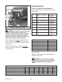
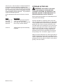
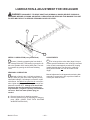
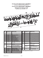
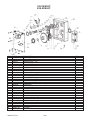
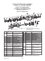
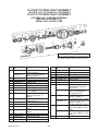
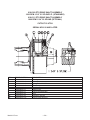
PTO DRIVE LINE
WARNING: BEFORE ATTEMPTING TO OPERATE THIS SPREADER, READ AND STUDY ALL
SAFETY INFORMATION. IN ADDITION, MAKE
SURE THAT EVERY INDIVIDUAL WHO OPERATES
OR WORKS WITH THE SPREADER, WHETHER
FAMILY MEMBER OR EMPLOYEE, IS FAMILIAR
WITH THESE SAFETY PRECAUTIONS.
WARNING: DISCONNECT PTO DRIVE
SHAFT AND HYDRAULIC HOSES (RELIEVE HYDRAULIC PRESSURE) BEFORE CLEANING, ADJUSTING, LUBRICATING OR SERVICING THIS
SPREADER. FAILURE TO HEED MAY RESULT IN
SERIOUS PERSONAL INJURY OR DEATH.
The Meyer V-Force Spreader is equipped with a cutout
type clutch on the implement half of the PTO drive line.
The clutch is designed to limit the amount of torque
transferred to the machine through the drive line. If
excessive torque is developed the clutch will disengage. A loud ratcheting sound will be heard and the
transfer of power to the machine will be disrupted. To
re-engage the machine simply shut down the PTO and
allow the drive line to come to a stop. The PTO can
then be re-engaged to restart the spreader. The cutout clutch will either re-engage upon shut down of the
PTO or just before it comes to a complete stop.
DRIVE LINE ATTACHMENT
The cutout clutch end of the PTO drive line must always be attached to the implement. The PTO drive
line is equipped with a 1 3/8-6 spline on the implement
half for attaching to the spreader. Remove the
M17-hexagon bolt from the splined hub and slide the
PTO onto the implement splined input shaft. Install the
hexagon bolt through the hub being sure the bolt is
falling into the groove on the splined shaft. Torque
tight using a metric size M17 6-point socket and torque
down to 75 ft. lbs. A M17 6-POINT METRIC SOCKET
MUST BE USED AS ROUNDING OF HEXAGON
BOLT AND INACCURACY OF TORQUE SETTINGS
COULD OCCUR.
If removal of the M-17 hexagon bolt is necessary, use
the same M-17 6-point socket and loosen bolt 1/2 turn.
Insert a ¼” drift punch in the hole on the opposite side
of the hexagon bolt and tap to loosen the seated portion of the bolt from the splined hub. Loosen in 1/2 turn
increments while tapping to loosen. After bolt seat has
been released, remove the bolt. If bolt is not unseated,
damage to the hexagon bolt will occur.
Attach the shield safety chain to a suitable area on the
spreader, preferably to the implement PTO steel
shield.
The cutout clutch will disengage if start up is done in
an abrupt or reckless manner. It also will disengage
from foreign materials entering the spinner area of the
spreader. It may also be possible to disengage the
clutch by overloading or flooding the spinners with free
flowing or liquid manure. If PTO clutch fails to re-engage it will be necessary to remove the foreign object
from the spreader before restarting. THERE IS NO
FIELD ADJUSTMENT ON THE CUTOUT CLUTCH.
DANGER: NEVER ENTER THE SPREADER
BOX FOR ANY REASON WITHOUT FIRST PERFORMING THESE STEPS:
l STOP THE TRACTOR, SHUT THE TRACTOR
OFF AND REMOVE THE KEY.
l SET THE PARKING BRAKE AND DISCONNECT
THE PTO DRIVE LINE FROM THE TRACTOR.
l DO NOT ALLOW OTHERS IN THE BOX.
ROTATING AUGERS CAN CRUSH AND DISMEMBER. FAILURE TO HEED MAY RESULT IN SERIOUS PERSONAL INJURY OR DEATH.
Model V-Force
1000 RPM
35.76” Min.
48.95” Max.
540 RPM
39.76” Min
52.95” Max.
FIGURE 5. PTO DRIVE LINE
DANGER: NEVER ENTER THE SPREADER
BOX FOR ANY REASON WITHOUT FIRST PERFORMING THESE STEPS:
l STOP THE TRACTOR, SHUT THE TRACTOR
OFF AND REMOVE THE KEY.
l SET THE PARKING BRAKE AND DISCONNECT
THE PTO DRIVE LINE FROM THE TRACTOR.
l DO NOT ALLOW OTHERS IN THE BOX.
ROTATING AUGERS CAN CRUSH AND DISMEMBER. FAILURE TO HEED MAY RESULT IN SERIOUS PERSONAL INJURY OR DEATH.
—16—
3.
Adjust the drawbar at 13-17” above the ground. Extend or shorten the drawbar so horizontal distance
from end of tractor PTO shaft to center of hitch pin
hole is 14” for 540 RPM 1-3/8-6 spline, (16” for optional 1000 RPM 1-3/8-21, 20” for 1000 RPM 1 3/4- 20
spline). Secure the drawbar so the hitch pin hole is located directly below the PTO drive line. PTO adapters
are not recommended as damage to the drive line may
occur. A hitch pin with a minimum diameter of 1” and
bottom retaining pin is recommended.
AN IMPROPERLY LOCATED HITCH POINT MAY
CAUSE DAMAGE TO THE UNIVERSAL JOINTS OF
THE PTO DRIVE SHAFT. CONFORMING TO THE
DRAWBAR AND PTO RELATIONSHIP SHOWN ON
FIGURE 1, PAGE 9 WILL ENSURE THAT THE PTO
DRIVESHAFT WILL NOT BECOME OVER
EXTENDED. USE THE CORRECT SETTING FOR
14” - 540RPM 1 3/8-6 or 16” - 1000RPM 1 3/8-21, or
20” - 1000 RPM 1 3/4- 20. WITH INITIAL HOOK-UP
TO YOUR NEW MEYER SPREADER TEST PTO
TRAVEL BY TURNING EQUIPMENT IN BOTH
DIRECTIONS OBSERVING THE MINIMUM AND
MAXIMUM TRAVEL DIMENSIONS AS SHOWN PER
DRAWING ON FIGURE 5, PAGE 16.
LUBRICATION
LUBRICATION
A high quality Lithium Base Grease should be used
FIGURE 6. PTO DRIVE LINE
4.
Shield bearings (Key #4)-Add 2-3 pumps.
FAILURE TO FREQUENTLY GREASE THE CV
CENTER HOUSING AND TELESCOPING
MEMBERS WILL REDUCE THE LIFE OF THE CV.
MAINTENANCE INFORMATION
It is extremely important to follow the maintenance
guidelines. If telescoping members become hard to
slide during normal operation, it is recommended the
shaft be taken apart, cleaned with solvent and
re-coated with grease before re-assembling. As a
minimum it is important this be done after each season
of use.
PRIOR TO USE
A. Using the CV Zerk (Key #2) place 20 pumps of
grease into the CV center housing. This should
be done with the drive line / CV as straight as
possible.
B. Slowly articulate the double joint through its
maximum joint angle several times.
C. Return the CV joint to its straight position and
insert additional grease into the CV Zerk (Key
#2) until grease is evident around the housing
and center sliding disk.
NORMAL OPERATION
A. Lubricate the following items after every eight
(8) hours of operation. If short rows and
frequent turning or other demanding conditions
exist, lubricate at four (4) hour intervals.
1.
Cross and bearings (Key #1)-Add grease
until it is purged around the seals.
2.
CV center housing (Key #2)-Add grease
until it is evident around the center sliding
disk.
Model V-Force
Telescoping members (Key #3)-Add
grease until it adequately covers the
sliding members. Take apart
occasionally to make sure adequate
lubrication is being added.
—17—
ADJUSTMENTS
WARNING: DISCONNECT PTO DRIVE SHAFT AND HYDRAULIC HOSES (RELIEVE HYDRAULIC
PRESSURE) BEFORE CLEANING, ADJUSTING, LUBRICATING OR SERVICING THIS SPREADER. FAILURE
TO HEED MAY RESULT IN SERIOUS PERSONAL INJURY OR DEATH.
SPINNER MATERIAL GUIDES
Regularly inspect and adjust two spinner material
guides located at both the LR and RR of the spreader.
Create a 1/8 - 3/8” clearance between material guides
and spinner teeth, figure 7. Maintain the recommended
clearances for maximum spreading pattern. Adjust to
prevent excessive manure build-up on material guide
inner surfaces. Adjust to prevent manure chunks or
foreign object lodging between material guides and
spinner teeth.
clearance. Do not turn in the opposite direction as
front chain tightener damage could occur. If foreign
objects enter the spinner area the rear pivot bolt on
the shear arm is designed to shear. The ½-13 x 3 ½”
grade 5 replacement machine bolts are stored under
the rear shield. For replacement install with ½” flat
washer on top and on bottom of block and tighten nylon locknut firmly.
NOTE: Excessive lodging can cause premature spinner tooth wear, “bent-over” or even breakage.
SHEAR ARM MATERIAL GUIDE
ADJUSTMENT
Adjustment for the 1/8- 3/8” clearance of each material
guide to spinner tooth is made by loosening the jam
nut on the linkage arm and turning the linkage arm to
either move the guide in closer or out farther from the
spinner teeth. After adjustment has been made for the
1/8- 3/8” clearance retighten the jam nut to hold the
material guide in place. Once recommended clearance is obtained turn spinners over by hand in the direction by which the spreader would turn to check
1/8- 3/8”
FIGURE 7. MATERIAL GUIDE CLEARANCE
Model V-Force
—18—
IDLER
NYLON
ROLLER
RH AUGER SPROCKET
The RH auger chain drive, figure 10, is automatically
tensioned by a spring loaded idler NYLON roller. The
extension spring should extend 3/4" from its neutral 4"
total length.
SPRING
LOADED
ADJUSTER
Manual adjustment for the automatic tensioning idler,
NYLON roller assembly is located at the right front
lower corner of the spreader tank.
ROLLER
CHAIN
FIGURE 10. RH AUGER CHAIN DRIVE
TRACKING
YOKE
IDLER
NYLON
ROLLERS
COMPRESSION SPRING
The LH auger chain drive is automatically tensioned
by a spring loaded heavy compression spring and
tracking yoke/idler, NYLON roller assembly, figure
11. The one heavy compression spring should be
compressed to 3-1/2" to 4" in length.
Manual adjustment for the automatic tensioning idler,
NYLON roller assembly is located at the left front corner of the spreader tank.
ROLLER CHAIN
LH AUGER SPROCKET
FIGURE 11. LH AUGER CHAIN DRIVE
SIDE LINE
SHAFT DRIVE
SPROCKET
IDLER NYLON ROLLER
The side shaft chain drive (PTO input shaft to the side
line shaft drive sprocket, figure 12) is automatically
tensioned by a spring loaded idler NYLON roller. The
extension spring should extend 2" from its neutral 5" total length.
Manual adjustment for the automatic tensioning idler,
NYLON roller assembly is located at the right front of
the spreader’s front bearing mounting plate.
PTO INPUT
SPRING LOADED
ADJUSTER
FIGURE 12. SIDE SHAFT CHAIN DRIVE
Model V-Force
—20—
LUBRICATION
WARNING: DISCONNECT PTO DRIVE SHAFT AND HYDRAULIC HOSES (RELIEVE HYDRAULIC
PRESSURE) BEFORE CLEANING, ADJUSTING, LUBRICATING OR SERVICING THIS MACHINE. FAILURE
TO HEED MAY RESULT IN SERIOUS PERSONAL INJURY OR DEATH.
DAILY LUBRICATION (every 8-12 loads)
L1 Grease (2) rear spinner lower bearings. These
bearings are grease line fitted to the LR frame channel
of the spreader.
L2 Keep the reservoir tank full of new 30 weight oil
for chain lubrication. The automatic chain oiler will lubricate the chains automatically every time the rear
gate, hydraulic cylinder is activated. The reservoir is
accessible by opening the front steel shield cover.
L3 Grease PTO Drive line (9) places with Lithium
grease every 8 hours.
L8 Grease (4) tandem wing pivots. Effectively grease
by jacking up the spreader to relieve pressure points
on the pivot shaft. Over greasing is not possible.
L9 Grease (2) flow control rear gate and lifting arm
pivot points. Grease gate pivot at center of flow control
rear gate. Grease lifting arm pivot support at LR of
spreader. Over greasing is not possible. Apply grease
to slot in gate lift arm.
L10 Grease (2) flow control rear gate slide guides.
With the flow control gate in the closed position grease
the zerk located on each side of the gate slides.
Grease 4-6 pumps on each side and run gate up and
down several times. Repeat the greasing until gate
slides are heavily lubricated. In freezing weather
dump used motor oil down each slide guide once a
week or more often if needed. Over greasing is not
possible.
IMPORTANT: GREASE 2 FITTINGS DAILY
L11 Grease (1) integral overrunning clutch at rear of
the PTO drive line. The zerk is on the yoke of the
L4 Grease (4) bearings supporting the two large jack
shaft reduction sprocket weldments on the front drive.
The zerks are accessible by opening the front steel
shielding cover and through the front bearing plate.
L5 Grease (2) auger shaft bushings. These bearings
are grease line fitted to the RF shield of the spreader.
Grease Daily, Minimum of 10 pumps. Over greasing is
not possible.
WEEKLY LUBRICATION (every 25-30 loads)
L6 Grease (2) PTO input shaft bearings. These bear-
clutch. Use Shell Super Duty or an equivalent lithium
grease.
ings are grease line fitted to the RF shield of the
spreader.
L12 Check regularly for any observable lube leakage
L7 Grease bearings on the RH side line shaft. The front
of the (3) gearboxes at the rear of the spreader. See
L12 under Monthly Lubrication.
bearing is zerk accessible through the RF steel shielding. The remaining rear bearings are located along the
RH side of the spreader tank, zerks accessible through
the steel shielding.
Model V-Force
—21—
MONTHLY LUBRICATION
L12 Keep the (3) gearboxes ½ full of liquid gear
grease at all times, capacity approximately 30 oz.
Check regularly for any observable leakage. If leakage
is excessive, replace required input/output shaft seals
as needed. Lubricate with a “Semi-Fluid, EP Lithium
Base, Gear Grease”.
L13 Clean and repack the wheel hubs with axle grease annually. Grease hub through zerk in hub monthly. Be
careful not to over grease and force seal out of back
side of hub.
(5 ROLLER
CHAINS)
(SHIELDS
REMOVED)
Model V-Force
—22—
LUBRICATION & ADJUSTMENT FOR 3RD AUGER
WARNING: DISCONNECT PTO DRIVE SHAFT AND HYDRAULIC HOSES (RELIEVE HYDRAULIC
PRESSURE) BEFORE CLEANING, ADJUSTING, LUBRICATING OR SERVICING THIS MACHINE. FAILURE
TO HEED MAY RESULT IN SERIOUS PERSONAL INJURY OF DEATH.
A1
COVER
L2
L1
WEEKLY LUBRICATION (every 25-30 loads)
)
L1 Grease (1) bearing supporting the front shaft of
the 3rd auger assembly. This bearing is grease line fitted to the spreader front, bearing back plate. The zerk
is accessible by opening the front steel shielding
cover.
ADJUSTMENTS
A1 The 3rd auger drive roller chain (large LH top reduction sprocket weldment to the 3rd auger) enclosed
in the oil bath is automatically tensioned by a spring
loaded idler/slide pipe. The tensioning, extension
spring should extend 3/4" from its neutral 4" total
length.
SEASONAL LUBRICATION
L2 Maintain oil level in the (1) oil bath enclosure at
the top, check plug line level. Check regularly for any
observable leakage. If oil leakage is excessive, repair
with silicone. Use #80-90 wt. gear lube oil or an equivalent. Lighter weight gear lube oil may be used in temperatures less than 20°F. Change oil in the oil bath
enclosure after the first season of use and regularly thereafter. (2.5 gallon capacity) Condensation
can occur. Drain out water (bottom plug) as
needed.
l
l
Manual adjustment for the automatic tensioning idler
assembly is located at the RF, top of the oil bath enclosure just under the cover.
Remove lower plug for draining purposes.
Remove reservoir cover or level plug for filling purpose. (SEAL COVER TIGHT WITH SILICONE
WHEN RE-INSTALLING.)
Model V-Force
—23—
INSTRUCTIONS FOR AUTOMATIC CHAIN OILER
WARNING: DISCONNECT PTO DRIVE
SHAFT AND HYDRAULIC HOSES (RELIEVE HYDRAULIC PRESSURE) BEFORE CLEANING, ADJUSTING, LUBRICATING OR SERVICING THIS
SPREADER. FAILURE TO HEED MAY RESULT IN
SERIOUS PERSONAL INJURY OR DEATH.
directly on top of sprockets. Adjust brush holders so
oiler brushes are pushed down into the roller chain approximately ½”. Carefully tighten up the ½”-20 nuts on
the oiler brushes. DO NOT over tighten as damage to
the brush will occur. The plastic threads of the oiler
brush will crack and then break off from the brush
body.
The automatic chain oiler attachment gives a squirt of
clean oil to all roller chains every time that the spreaders rear gate, hydraulic cylinder is activated. In this
way, the spreaders roller chains get oiled in direct proportion to the number of hydraulic cylinder cycles of
the rear gate. This assures adequate lubrication.
New 30 weight oil, which is placed in the reservoir tank
mounted on the spreader, is all that is needed to properly lubricate all roller chains and sprockets. The automatic chain oiler does not use any oil from the tractors
hydraulic system. The hydraulic hose connected to
the bottom of the oiler pump only serves to power the
piston in the pump every time that the spreaders rear
gate is opened.
Should the oil reservoir tank run dry, pour about a ½
cup of clean 30 weight oil into the tank. Allow time for
the oil to run down into the oiler pump slowly and allow
air to escape. After thirty minutes to one hour has
passed, finish filling the reservoir tank. Make sure that
all fittings and brackets are tight when finished filling
the tank.
IMPORTANT! The 5/32” oil line tubing can only be
removed from an oiler brush by pushing in on the
red plastic ring and pulling the tubing out while
holding the ring down.
The oiler pump is set at the factory to deliver the maximum amount of oil per cycle. If less oil is desired,
loosen the jam nut on the bottom of the pump and
screw in the adjusting shaft 1/4” or approximately 5
turns. It is not recommended to screw the shaft into
the bottom of the oiler pump more than 15 turns as
this may not allow for proper lubrication of the roller
chains.
IMPORTANT! Always use new 30 weight oil. In
cold weather, use a SAE 10 or a mixture of two
parts of 30 weight oil to one part diesel fuel.
WARNING: HYDRAULIC FLUID ESCAPING
UNDER PRESSURE CAN HAVE SUFFICIENT
FORCE TO PENETRATE SKIN. KEEP ALL HOSES
AND CONNECTIONS IN GOOD SERVICEABLE
CONDITION. FAILURE TO HEED MAY RESULT IN
SERIOUS PERSONAL INJURY OR DEATH.
While running the tractors hydraulics only, open and
close the spreaders rear gate several times. This will
cycle the hydraulic cylinder leading to the oiler pump.
Keep cycling until oil can be seen in all of the oil lines
leading to the oiler brushes. (If you experience problems priming the oiler pump, you may need to bleed
air out of the hydraulic hose where it is connected to
the pump. Crack the fitting until oil comes out then
re-tighten.) The hydraulic cylinder that the oiler pump
is tied into is double acting and must reach 300 PSI of
pressure to actuate the pump.
When replacing oiler brushes into brush holders, use
regular ½”-20 nuts. Tighten nut finger tight initially as
some adjustment may be needed later. For best results, place brush holders over top of roller chains and
Model V-Force
—24—
This Page Intentionally Blank
Model V-Force
—25—
REPAIR PARTS
OIL-KIT
35
Model V-Force
—26—
OIL-KIT
KEY
1
2
3
4
5
6
7
8
9
10
11
12
13
14
15
16
17
18
19
20
21
22
23
24
25
26
27
28
29
30
31
32
33
34
35
PART NO.
952-0001-1-33
952-0001-1-27
952-0001-1-28
952-0001-1-13
952-0001-1-9
952-0001-1-11
952-0001-1-10
952-0001-1-5
952-0001-1-1
952-0001-1-8
952-0001-1-4
952-0001-1-6
952-0001-1-7
952-0001-1-2
952-0001-1-16
952-0001-1-3
952-0001-1-32
952-0001-1-18
952-0001-1-19
952-0001-1-20
952-0001-1-21
952-0001-1-25
813-5020-Z
952-0001-1-17
952-0001-1-14
955-3803
952-0001-1-30
952-0001-1-31
08-0050
952-0001-2
952-0001-3
952-0001-4
952-0001-5
952-0001-6
952-0001-1-36
Model V-Force
OEM PART NO.
170-4515
576895
576894
2510
1012
3520
1019
1004
21999-0222
2-022-N552-90
1033
2-026-N552-90
2-113-N674-70
21999-0224
6010
4511
2107001U
2550
M-4555
7010
7012
4514
2016
2511
4517
170-000-6
DESCRIPTION
Holder, Manifold Valve Assembly
Sleeve Nut Brass
5/32 Brass Ferrule
Holder, Manifold Valve
One Way Valve (Schrader Valve)
Bearing, 7/16" Stainless
Screen Flat Oiler .906 Dia
Spring, Oiler
Oiler Body 8 Port Black
O Ring, Oiler Piston 2-022 90 Dur
Piston, 2 Groove Alum, Short
Washer, Rubber Lube Minder
O Ring, Adj End Cap Plunger
Adj End Cap Oil Black
½-20 Jam Nut
Plunger, Brass Adj End Cap
1/8" Hex Head Pipe Plug
Reservoir Two Quart Tank
Hydraulic Hose Assembly Meyer Mfg.
Tubing 5/8" ID Clear Polybraid
Tubing 5/32" Nylon (Feet)
Brush Assembly No 5/32 Insert
½-20 Plated Nut
Bracket Oiler Mtg Pump
5/32 Push In Insert (Nycoil)
BM Pipe Tee 3/8 x 3/8 x 3/8
1" Hose Clamp
U-Bolt Assembly #13
5/16" Closed "J" Clip
#80 Brush Holder
Left #120 Auger Chain Brush Holder
Right #120 Auger Chain Brush Holder
Oiler Tank Mount Plate
#80 Center Shaft Chain Brush Holder
Oiler Body Pump Assy, Complete
—27—
FRONT SHIELD & SIDE SHAFT DRIVE
KEY PART NO.
1
914-3801
2
910-0013
3
4
5
6
7
8
9
10
11
12
13
DESCRIPTION
1-3/8" Pillow Block Bearing
80B18 Sprocket 1-3/8" Bore,
5/16" Keyway
935-0002
5/16x5/16x2-1/4" Hardened
Key
923-3837
SV7500 Front Side Shaft
925-3882
Side Shaft Tightener Assy.
Complete
46-3600-12
Operating Procedure Decal
46-3600-14
Maintenance Warning Decal
33-0044
Manual Holder W/Cap
912-0001
Nylon Roller
925-3882-1
Side Shaft Chain Tightener
Weldment
911-0070
#80-97 Link Roller Chain
911-0001
#80-98 Link Roller Chain (Gin
Trash/Poultry)
808-150-300- 10 Ga. Machine Bushing (As
10
Required)
910-0039
80B22T Sprocket 1-1/2" Bore,
3/8" Keyway
910-0036
80B24 Sprocket 1-1/2" Bore,
3/8" Keyway (Gin Trash)
Model V-Force
KEY PART NO.
14
808-1.5-2.2510
15
813-3118-Z
16
808-1-1.5-18
17
18
19
20
21
22
22a
23
24
25
—28—
DESCRIPTION
10 Ga. Machine Bushing (As Required)
5/16-16 Nut Zinc
18 Ga. Machine Bushing (As Required)
933-3804
5/16-18 x 4" Eye Bolt Fully
Threaded
808-1.25-1.87 1-1/4 ID x 1-7/8OD x 14 Ga. Ma5-14
chine Bushing
929-0003
Tightener Spring
38-0013
5/16 x 1-3/4" Roll Pin
955-3703
Gas Assist Spring (Prior to 08 serial #'s)
925-5006-1
Shield Support Arm (08 Serial #'s
& Later)
924-3821
Main Front Shield Assy. (Prior to
08 serial #'s)
924-3827
Main Front Shield Assy. (08 Serial #'s & Later)
32-0018-1
Heavy Duty Latch
924-3826
Left Front Shield
924-5001
Right Front Shield Welded Assy.
925-3762
Gate Indicator Pointer Assy.
(Model 7500 Only)
AUGER DRIVE, PRIMARY REDUCTION
KEY PART NO.
1
933-3628
2
3
4
5
5A
5B
6
7
8
DESCRIPTION
Copper Tube Grease Line
25" (includes zerk, fittings)
38-0013
Roll Pin, 5/16" x 1-3/4"
925-3883-1
First Reduction Tightener Assembly Arm Weldment
808-.75-1.25-14 Machine Bushing, 14GA
912-0012
Tightener Roller 1-3/8" Nylon
Complete
912-0012-1
Nylon Roller Only
912-0012-2
Inner Sleeve
851-7510-2Z
3/4"-10x2" Bolt, GR5
911-0032
Chain #80x87 pitches
911-0071
#80-94 (84+10) Roller Chain
(Gin Trash)
910-0039
Sprocket 80B22 1-1/2" Bore,
3/8" Keyway (10 RPM on Augers) STANDARD
910-0096
Split Sprocket 80B40, 3/8"
Keyway, (20 RPM Augers)
(Gin Trash Only
Ser.#SV087500360 & Later)
910-0033
Sprocket 80B15 1-1/2" Bore,
3/8" Keyway (7 RPM on Augers)
Model V-Force
KEY PART NO.
8
910-0005
910-0079
9
914-3602
10
11
12
13
925-3606
925-3883
931-3810
923-3833
923-3833-XL
14
910-0063
15
16
17
18
19
20
21
813-3118-Z
933-3804
935-0001
929-0003
808-1-1.5-18
35-0010
933-3632
—29—
DESCRIPTION
Sprocket 80B12 1-1/2" Bore,
3/8" Keyway (5 RPM on Augers)
Split Sprocket 80B32 1-1/2"
Bore, 3/8" Keyway (16 RPM
Augers Gin Trash Only)
Bearing 4 Bolt Flange, 1-1/2"
Bore
Front Bearing Plate-Bent
Tightener Assembly Complete
CV/OR PTO Shied Assembly
CV/OR Input Drive
Shaft-Splined 16-3/4" Long
CV/OR Input Drive
Shaft-Splined 33-3/4" Long
(Extended Hitch Package)
Welded Sprocket Assy, RH,
80A60x80A12
5/16" Regular Nut
5/16"x4" Full Thread Eye Bolt
3/8x3/8x2" Hardened Key
Spring
Machine Bushing, 18GA
3/8"x3/8"x1-1/2" Square Key
Copper Tube Grease Line 37"
(includes zerk fittings)
AUGER DRIVE, SECONDARY REDUCTION
KEY
1
2
3
4
5
6
6A
6B
7
8
9
10
11
12
13
14
15
16
17
Model V-Force
PART NO.
14-0031
38-0013
910-0063
851-7510-3Z
911-0018
912-0013
912-0013-1
912-0013-2
808-.75-1.25-14
925-3884-1
813-3118-Z
933-3804
30-0002
929-0003
808-1-1.5-18
910-0064
925-3884
30-0009
30-0014
DESCRIPTION
Bearing, 4 Bolt, 2" Bore
Roll Pin, 5/16" x 1-3/4"
Welded Sprocket Assy, RH, 8060x8012
3/4"-10x3" Bolt, GR5
Chain #80x73 pitches
Tightener Roller 2" Nylon Complete
Nylon Roller Only
Inner sleeve
Machine Bushing, 14GA
Second Reduction Tightener Arm Weldment
5/16" Regular Nut
5/16"x4" Full Thread Eye Bolt
1/8" NPT Zerk
Spring
Machine Bushing, 18GA
Welded Sprocket Assy, LH, 80/60 x 120/9
Tightener Assembly Complete
1/8" NPT Coupler
1/8" NPT x 3 ½" Nipple
—30—
RH AUGER DRIVE, FINAL REDUCTION
Install (#120-56) Roller Chain, Key #13
W/Connector Link Cotter Pins Facing
Towards Front Of Spreader.
KEY PART NO.
1
33-0025
2
910-0064
3
910-0101
831-5020-1.75
884-5020
831-5618-1.75
884-5618
910-0028
4
5
813-3118-Z
933-3804
6
913-3801-1
Model V-Force
DESCRIPTION
2-1/2" Retaining Ring
Welded Sprocket Assy, LH,
80A60x120A9
Shear Sprocket Assy.
120B33 (Standard 7500, Optional 7400)
½-20 x 1-3/4" Allen Head
Cap Screw Grade 8 (Standard)
½-20 Top Locknut Grade 8
(Standard)
9/16-18 x 1-3/4" Allen Head
Cap Screw Grade 8 (Optional)
9/16-18 Top Locknut Grade
8 (Optional)
120B33 Spline Sprocket
(Standard 7400)
5/16" Regular Nut
5/16"x4" Full Thread Eye
Bolt
Auger Bushing Only 2-1/2"
ID x 2-3/4" OD x 2 3/4" Long
KEY PART NO.
7
925-3834
8
9
10
10A
10B
11
12
13
14
15
16
17
18
19
—31—
DESCRIPTION
Front Auger Bearing Plate
Assy. With Bushing, RH
933-3621
3/4" Jam Nut
808-.75-1.25-14 Machine Bushing, 14GA
912-0013
Tightener Roller, 2" Nylon
Complete
912-0013-1
Nylon Roller Only
912-0013-2
Inner Sleeve
925-3848-7
Tightener Arm Welded Assy
929-3601
Spring
911-0023
Chain #120x56 pitches
851-7510-3.5Z 3/4"-10x3 ½" Bolt, GR5
805-0010-Z
1" Flat Washer
38-0013
5/16"x1-3/4" Roll Pin
925-3822-6
2 Links 3/16" Proof Coil
Chain
933-3619
Copper Tube Grease Line
28" (includes zerk, fittings)
925-3848
Tightener Arm Assembly
Complete
LH AUGER DRIVE, FINAL REDUCTION
Install (#120-72) Roller Chain, Key #21
W/Connector Link Cotter Pins Facing
Towards Rear Of Spreader.
Model V-Force
—32—
LH AUGER DRIVE, FINAL REDUCTION
KEY
1
2
3
4
5
6
7
8
9
10
11
12
13
14
15
16
17
18
19
20
20A
20B
21
21A
22
23
24
25
26
27
28
29
30
31
32
33
34
35
Model V-Force
PART NO.
14-0031
925-3873
910-0064
808-.75-1.25-14
30-0014
30-0002
925-3846-2
851-7510-6Z
925-3870-1
914-3807A
925-3833
913-3801-1
813-7510-Z
933-3621
925-3841
29-0009
925-3885-1
925-3843
925-3839
912-0014
912-0014-1
912-0014-2
911-0024
911-0026
912-0001
925-3838
925-3842
910-0101
831-5020-1.75
884-5020
831-5618-1.75
884-5618
910-0028
933-3637
33-0025
925-3807-3
851-5013-1.25Z
808-1.25-1.875-10
925-3816-2
925-3816
925-3869
30-0009
914-3801
DESCRIPTION
Bearing, 4 Bolt Flange, 2" Bore
Front Bearing Mounting Plate
Welded Sprocket Assy, LH, 80A60x120A9
Machine Bushing, 14GA
1/8" NPT x 3 ½" Nipple
1/8" NPT Zerk
4" Snugulator Support Arm Assy
3/4"-10x6" Bolt, GR5
Bearing Back Plate
Bearing, 4-Bolt, 2-1/2" Bore
Front Auger Bearing Plate Assy.. with Bushing, LH
Auger Bushing Only 2-1/2" IDx2-3/4" ODx2 3/4" Long
3/4" Nut, Regular
3/4" Jam Nut
Spring Tightener Guide
Spring, Compression
Main Tightener Channel
Inner Slide Nut Assembly
3/4"x8 ½" Bolt Assy
Tightener Roller, 4" Nylon Complete
Nylon Roller Only
Inner Sleeve
Chain #120x72 pitches
#120 Connector Link Only
Nylon Roller
Tightener Weldment Yoke
Outer Slide Nut Assembly
Shear Sprocket Assy. 120B33 (Standard 7500, Optional 7400)
½-20 x 1-3/4" Allen Head Cap Screw Grade 8 (Standard)
½-20 Top Locknut Grade 8 (Standard)
9/16-18 x 1-3/4" Allen Head Cap Screw Grade 8 (Optional)
9/16-18 Top Locknut Grade 8 (Optional)
120B33 Spline Sprocket (Standard 7400)
Copper Tube Grease Line 51" (includes zerk, fittings)
2-1/2" Retaining Ring
Nylon Roller Retaining Washer
½"-13x1.25" Bolt, GR5
Machine Bushing, 10GA
Chain Hold Down Bracket
Roller Assembly Complete
Support For Bearing
1/8" NPT Coupler
1-3/8" Pillow Block Bearing
—33—
BOX, AUGERS & SIDE SHAFT
Model V-Force
—34—
BOX, AUGERS & SIDE SHAFT
KEY
1
2
3
4
5
6
7
8
9
10
11
11
12
13
14
15
16
17
18
19
20
21
22
23
24
25
26
27
28a
29
30
31
32
33
34
35
36
37
PART NO.
901-3903
901-3915
901-3801-82
923-3837
14-0049
937-0002
923-3827
924-5000-F
924-5000-R
901-3909
901-3934
955-3806
933-3602
810-3816-Z
926-3823
926-3822
926-3802-2
926-3801-2
926-3801-8
933-3802
926-3801-5
33-0025
933-3801
933-3801-NSM-09
925-5000
901-3893
881-1008-5Z
884-1008
925-3771-9
901-3840-1
925-3771-4
956-3803
929-3801
956-3803-1
955-3611
955-3701
55-0113
955-3803
955-3609
955-3833
901-3801-40
901-3918-1
924-5012-1
823-.25-5Z
901-3916
901-3917
Model V-Force
DESCRIPTION
Main Welded Body, 7500
Main Welded Body, 7400
Adj. Hitch Plate, 1” Pin
SV7000 Front Side Shaft
1-3/8" 2-Bolt Bearing
Shaft Coupler 1-3/8"
Rear Side Shaft 141"
SV74/7500 Front Side Shield
SV74/7500 Rear Side Shield
SV7500 Splash Guard Welded Assy.
SV7400 Splash Gaurd Welded Assy
Side Hydraulic Pipe 74/7500
Hydraulic Pipe Bracket Clamp
3/8" Spinlock Nut
SV75/7400 RH T-Post Auger Assy
SV75/7400 LH T-Post Auger Assy
3/8" Sectional Flighting x 20" RH
3/8" Sectional Flighting x 20" LH
Auger Flighting Support Gusset
Front Auger Washer - Steel (Prior to Serial #SV097500211)
Splined Shaft
2-1/2" Retaining Ring
Bronze Washer (Prior to Serial #SV097500211)
Nylon Thrust Bearing 2-1/2x5x13/16" (Serial #SV097500211 & Later)
SV7500 T-Post Hold-down Assy W/Nylon-Wide
SV7400 T-Post Hold-down Assy W/Nylon-Narrow
1-08x5" M.B.. Grade 8
1-08 Top Locknut Grade 8
7500 Nylon Bearing (2 per Auger, 4-per Spreader)
7400 Nylon Bearing (2 per Auger, 4-per Spreader)
Holdown Collar
Side Wind Jack
Hose Holder Spring
Square Jack Mount Tube
Hydraulic Hose 108"
Hydraulic Hose 132" (Extended Hitch Package)
Male Hydraulic Tip
3/8" Black T-Fitting
Coupler 3/8"NPT
3/8"x27" Hyd. Hose w/Swivel
Scraper Holder Ring
7400 Flat Splash Gaurd
Lower Sprocket Shield w/ Hinges
1/4 x 5” Hair Pin
7400 L. Splash Gaurd Gusset
7400 R. Splash Gaurd Gusset
—35—
UNLOADING GATE & TRIP PAN DOORS
PRIOR TO 08 S/N’S
PRIOR TO 08 S/N’S
PRIOR TO 08 S/N’S
Model V-Force
—36—
UNLOADING GATE & TRIP PAN DOORS
KEY
1
2
3
4
5
6
7
8
9
10
11
12
13
14
15
16
17
18
19
20
21
22
23
24
25
26
27
28
29
30
31
32
33
34
35
36
37
38
39
40
41
42
43
44
45
46
47
48
49
50
51
52
53
54
55
PART NO.
925-5005
901-3903-34
949-3753
901-3908
901-3912
901-3929
955-3804-1
913-3808
925-5001
925-13901
925-13905
925-13900
925-13904
901-3845-1
924-5003
924-5004
924-5005
924-5006
924-5007
924-5009
924-5008
925-5003
925-5002
925-5006-1
925-13803-KIT
925-13804-1
925-13903
901-5000-1
925-5006-2
32-0032-2
32-0032-3
925-13902
75-0304
925-13803
884-1014-Z
75-0305-2
75-0413-1A
851-5013-3.5Z
827-2528-.38
805-0050-Z
815-5013-Z
929-0003
49-0099
924-5010-1
901-3913-OS
901-3913
901-3914
805-0125
822-0050-Z
33-0030-RH
30-0001
949-3704
924-5002
924-5011
32-0032
75-0305-1
925-5016
826-1008
925-3915
Model V-Force
DESCRIPTION
Spinner Deflector Welded Assy.
Spinner Mount Channel
Poly Gate Slides
Back Gate Welded Assy.
Gate Lifting Arm 7500 Only
Gate Lifting Arm W/tube 7400 Only
3X12" Hydraulic Cylinder
1.504IDx2.000ODx1" Bronze Bushing
Pivot Shaft Support Assy.
R. Material Guide Assy. (Prior to 08 serial #'s)
R. Material Guide Assy. (08 serial #'s & later)
L. Material Guide Assy. (Prior to 08 serial #'s)
L. Material Guide Assy. (08 serial #'s & later)
Rear Shield Mount Plate
Stainless Steel Rear Shield (Prior to 08 serial #'s)
Rear Shield Formed Channel (Prior to 08 serial #'s)
Right Lower Shield (Prior to 08 serial #'s)
Left Shield End Cap (Prior to 08 serial #'s)
Belting Hinge Mount Channel (Prior to 08 serial #'s)
Right Rear Top Shield (Prior to 08 serial #'s)
Right Shield End Cap (Prior to 08 serial #'s)
Gate Indicator Arm Linkage Assy. (7500 Model Only)
Indicator Arm Linkage Assy. (7500 Model Only)
Rear Shield Support Arm
Material Guide Linkage Arm (One Side Only)(Prior to 08 serial #'s)
Shear Bolt Sleeve 1" Long (Prior to 08 serial #'s)
Shear Bolt Sleeve 1-3/8" Long (Prior to 08 serial #'s)
Rear Gate Slide Guide
Support Arm Upper Bracket
3-1/2" Rubber T-Latch
Sheared Lower T-Catch
RH Tie Rod Eyelet Welded Assy. W/Jam Nut (Prior to 08 serial #'s)
LH Tie Rod Eyelet W/Jam Nut (Prior to 08 serial #'s)
Material Guide Linkage Arm Assy. (Prior to 08 serial #'s)
Top Locknut 1-14
Jam Nut 1-14
1-14x4" Grade 5 Machine Bolt (Prior to 08 serial #'s)
1/2-13x3-1/2" Grade 5 Machine Bolt (Prior to 08 serial #'s)
1/4-28X3/8" Set Screw (Prior to 08 serial #'s)
1/2" Flat Washer (Prior to 08 serial #'s)
1/2-13 Nylon Insert Locknut (Prior to 08 serial #'s)
Extension Spring (Prior to 08 serial #'s)
Belting Hinge (Prior to 08 serial #'s)
Stainless Steel Belting Hinge Top Strip (Prior to 08 serial #'s)
Lower Cylinder Pivot plate Welded Assy. (Prior to 08 serial #'s)
Lower Cylinder Pivot plate Welded Assy. (08 Serial #'s & Later)
Gate Lift Arm Pivot Shaft Assy.
1-1/4" Flat Washer
1/2" Split Lock washer
1/2x3/4 Drilled Grease Bolt
1/4-28 Straight Grease Fitting
Poly Top Gate Seal
Right Rear Corner Shield (08 serial #'s & later)
Rear Main Shield Assy. (08 Serial #'s & Later)
3-1/2" Rubber T-Latch w/Catch
Right Hand Tie Rod Eye
Shear Arm Welded Assy.
1-08 Jam Nut
Optional Rear Channel to Body Seal
—37—
QTY
1
2
2
1
1
1
1
1
1
1
1
1
1
1
1
1
1
1
1
1
1
1
1
1
2
2
2
2
1
1
1
2
2
2
2
2
2
2
4
12
6
2
1
1
1
1
1
1
1
1
1
1
1
1
1
2
2
4
1
SPINNERS & GEARBOX SHAFT DRIVE
PADDLE OPTIONS
Model V-Force
—38—
SPINNERS & GEARBOX SHAFT DRIVE
KEY
1
2
3
4
5
6
7
8
9
10
11
12
13
14
15
16
17
18
19
20
21
22
23
24
25
26
27
28
Model V-Force
PART NO.
901-3753-10
901-3753-19
19-0041
935-0002
937-0014-1
19-0042
19-0043
901-3906
901-3907
914-3604
901-3906-6
901-3753-20
901-3907-1
937-0009-2
937-0009-3
808-1.38-2.5-14
808-1.38-2.5-18
808-1.38-2.5-10
901-3855-4
851-6311-2Z
815-6311-Z
921-0001
850-6311-1.5Z
815-6311-Z
933-3625
933-3626
937-0014
937-0002
35-0017
901-3754-2
901-3753-13
DESCRIPTION
Spinner Paddle, 2 Per Spinner
8865/7000 LH Aggressive Spinner Paddle
Gearbox, Left, Cast
5/16x5/16x2-1/4" Hardened Key
Shaft Coupler, 1-3/8” Bore (4 Required)
Gearbox, Center w/Thru Shaft, Cast
Gearbox, Right, Cast
Right Spinner Assy W/Shaft, Less Paddles
Left Spinner Assy W/Shaft, Less Paddles
Bearing 4 Bolt Flange 1-3/8” Bore-Ductile
SV7000 Spinner Shaft
8865/7000 RH Aggressive Spinner Paddle
SV7000 Spinner Sand Paddle, (Reversible)
Coupler Chain
Connecting Link
Machine Bushing, 14GA
Machine Bushing, 18GA
Machine Bushing, 10GA
Splined Hub
5/8”-11 x 2” Bolt, GR5
5/8”-11 Nylon Insert Lock Nut
1-3/8” One Piece Set Collar
5/8x11 Grade 5 Carriage Bolt
5/8-11 Nylon Insert Locknut
Copper Tube Grease Line 57” (Includes zerk, fittings)
Copper Tube Grease Line 31” (Includes zerk, fittings)
1 3/8” Coupler Assy. Kit w/Chain & Keys
Shaft Coupler, 1-3/8” Bore with 5/16” Key w/4 Set Screws
5/16x5/16x4-½” Key
LH Poultry/Sludge/Gin Trash Paddle
RH Poultry/Sludge/Gin Trash Paddle
—39—
SPINNER GEAR REDUCERS
USE FLUID GEAR GREASE ONLY.
DO NOT USE GREASE FOR LUBRICANT.
Model V-Force
KEY
1
2
3
4
5
8
9
10
11
12
13
PART NO.
19-0022-1-PF
19-0018-2
19-0018-3
19-0016-3
19-0018-4
19-0022-2-PF
19-0018-7-PF
19-0043-1
19-0042-1
19-0041-1
19-0041-2
14
16
17
18
19
20
19-0024-20
19-0016-5
19-0023-1-PF
19-0023-2
55-0107
19-0041-3
DESCRIPTION
Splined Pinion Output Shaft/Gear Assy
Seal
Bearing Cone
Bearing Cup
Retaining Ring
Center Gearbox Cross Thru Shaft/Gear Assy
RH/LH Gearbox Cross Input Shaft/Gear Assy
Corner Gearbox Casting (tapped holes) Cast
Center Gearbox Casting (tapped holes) Cast
LH Gearbox Casting (tapped holes) Cast
RH/LH/Center Gearbox Casting (thru holes)
Cast
Bolt 1 ½" SHCS
Plug ½"NPT Plain
RH Gearbox Pinion Output Shaft/Gear Assy
3/8" Drilled Fill Plug Bolt
Breather Plug
Gearbox End Cap
—40—
HUBS, AXLE & TANDEM AXLE ASSEMBLY
KEY PART NO.
7500
1
75-0207
2
75-0207-2
3
75-0207-3
4
75-0207-4
5
75-0202-4
6
75-0202-3
7
75-0205-7
8
75-0205-8
9
75-0205-9
10
75-0205-10
11
75-0205-11
12
75-0207-12
13
75-0207-1
14
901-3905
15
901-3904-1-3
16
901-3904
901-3927
17
901-3911
901-3926
18
955-3761
19
955-3762
20
30-0020
Model V-Force
DESCRIPTION
7400
75-0205
75-0205-2
75-0205-3
75-0205-4
75-0202-4
75-0202-3
75-0205-7
75-0205-8
75-0205-9
75-0205-10
75-0205-11
75-0205-12
75-0205-1
901-3905
901-3904-1-3
901-3921
901-3922
955-3761
955-3762
30-0020
Hub Assembly Complete
Seal
Bearing Cone
Bearing Cup
Bearing Cup
Bearing Cone
Washer
Nut
Cotter Pin
Hub Cap
Lug Nut
Stud Bolt
Hub Only w/Races & Studs
Axle Pivot Sleeve Welded Assy.
Nylon Pivot Sleeve
Left O-Beam Welded Assy Less Hubs
Left O-Beam Welded Assy Less Hubs-(Gin Trash)
Right O-Beam Welded Assy Less Hubs
Right O-Beam Welded Assy Less Hubs-(Gin Trash)
3/16x10" Grease Hose
3/16x16" Grease Hose
1/8” NPT Street L
—41—
THIRD AUGER
Model V-Force
—42—
THIRD AUGER
KEY
1
2
3
4
5
6
7
8
9
10
11
12
13
14
15
16
17
18
19
20
Model V-Force
PART NO.
929-3601
35-0008
910-0050
14-0031
925-3866
911-0033
35-0010
910-0005
925-3861
926-5000
933-3606
913-3805
925-3865
955-3809
933-3627
933-3804
925-3825
813-3118-Z
851-6311-2Z
814-6311-Z
DESCRIPTION
Extension Spring
½"x1/2"x2" Square Key
80B26 Sprocket 2" Bore, ½" Keyway
Bearing, 4-Bolt Flange, 2" B
Chain Tightener Bracket Wldmt.
#80-36 Roller Chain w/Connector.
3/8"x3/8"x1-1/2 Square Key
80B12, 1-1/2"B, 3/8" Keyway
Oil Bath Cover
74/7500 3rd Auger Welded Assembly
Bronze Washer
Bronze Bushing
3rd Auger Rear Shaft Support Sleeve w/Bushing
3/8" Square Head Steel Pipe Plug
Copper Tube Grease Line 14-1/2" (includes zerk, fittings)
Eyebolt, Full Thread
Tightener Angle Clip
5/16-18 Nut Zinc
5/8"-11x2" Gr. 5 Machine Bolt
5/8"-11 Center Lock Nut
—43—
918-0212 PTO DRIVE SHAFT ASSEMBLY
(PRIOR TO SERIAL #SV087500201)
918-0312 PTO DRIVE SHAFT ASSEMBLY
(SERIAL #SV087500201 & LATER)
540 RPM 1-3/8 – 6 SPLINE YOKE
WWE2480 (80 DEGREE C.V.)
KEY
1
2
3
4
5
6
7
8
9
10
11
12
13
14
15
16
MEYER PART
NO.
918-0212-1-1
DESCRIPTION
KEY
Yoke 1-3/8"-6 Splined Assembly
918-0208-1-2
Grease Zerk in item 3
918-0208-1-3
Double Yoke
918-0208-1-4
Inboard Yoke
918-0208-1-5
Cross and Bearing Kit
918-0208-1-6
Spring Pin 10 x 80
918-0208-2-1
Cross and Bearing Kit
918-0208-1-14 Profile and Sleeve Wa
918-0208-2-2
Overrunning Clutch & 1bGA
Profile Assy.
918-0208-2-3-1 Clamping Cone Bolt (Included
in Item 11)
918-0212-2-1
Cut Out Clutch 1900NM (Prior
to Serial #SV087500201)
918-0312-1-1
Cut Out Clutch 1900NM (Serial #SV087500201 & Later)
918-0208-2-4
Bearing Ring SC25
918-0208-2-5
Outer Shield Tube OVL
918-0208-1-7
Inner shield Tube Round
918-0208-1-8
CV Cone & Bearing Assy.
918-0208-1-9
Shield Cone 3 Rib
Model V-Force
17
18
19
20
21
22
23
24
25
26
27
28
MEYER PART
NO.
918-0208-2-6
918-0208-2-7
918-0208-2-8
918-0208-1-10
918-0208-2-9
918-0208-1-11
918-0208-1-12
918-0208-1-13
918-0208-2-10
918-0212-1
DESCRIPTION
Shield Cone 8 Rib
Safety Chain
Decal Out-In Item 13
Decal In-In Item 8
Screw-In Item 15,16 & 17
Support Bearing
Zerk-In Item 8
Cross and Bearing Kit
Decal-K64
1-3/8-6 Spline Tractor Half Assembly
918-0212-2
540 RPM Implement Half Assy
(Prior to Serial #
SV087500201)
918-0312-1
540 RPM Implement Half Assy
(Serial # SV087500201 &
Later)
918-0208-1-1-1 AS-Lock Kit For Item 1 (Inc.
Ring, Collar & Balls)
See Next Page For Cut Out Clutch
—44—
(PRIOR TO SERIAL #SV087500201)
540 RPM 1-3/8 – 6 SPLINE YOKE
WWE2480 (80 DEGREE C.V.)
KEY
1
2
3
4
5
6
7
8
NS
NS
MEYER PART NO.
918-0208-2-3-2
918-0208-2-3-3
918-0208-2-3-4
918-0208-2-3-5
918-0208-2-3-6
918-0208-2-3-7
918-0208-2-3-1
918-0208-2-3-8
918-0208-2-3-9
918-0208-2-3-11
DESCRIPTION
Housing
Hub
Spring Pack 1900NM
Washer
Retaining Ring
Sealing Ring
Clamp Cone Assembly
Cam
Bushing-In Item #2
Shim Kit
(SERIAL #SV087500201 & LATER)
540 RPM 1-3/8 – 6 SPLINE YOKE
WWE2480 (80 DEGREE C.V.)
KEY
1
2
3
4
5
6
7
8
NS
NS
Model V-Force
—45—
MEYER PART NO.
918-0308-2-2-1
918-0308-2-2-2
918-0312-1-1-1
918-0208-2-3-5
918-0208-2-3-6
918-0208-2-3-7
918-0208-2-3-1
918-0308-2-2-4
918-0312-1-1-2
918-0208-2-3-11
DESCRIPTION
Housing
Hub
Spring Pack 1900NM
Washer
Retaining Ring
Sealing Ring
Clamp Cone Assembly
Cam
Bushing-In Item #2
Shim Kit
1000 RPM KIT
SVS-RPM-KIT
KEY
1
2
3
4
5
6
7
8
9
10
11
12
13
14
15
16
17
18
19
20
21
22
23
24
25
26
27
28
29
NS
NS
NS
PART NO.
19-0002-17
29-0015
33-0012
33-0021
33-0039
35-0010
805-0031-Z
806-0031-Z
851-3118-.75Z
910-0005
911-0045-HD
912-0010
914-3809
914-3816
914-3817
923-3834
923-3835
925-3890-1
925-3891-1
925-3892-10
925-3892-1
925-3892-9
933-3812
955-3809
808-1.5-2.25-14
814-5013-Z
925-3892-7
805-0050-Z
810-5013-Z
48-0044
46-0001-23
46-2636-11
Model V-Force
DESCRIPTION
Vent Plug
Tightener Spring
Retaining Ring 1-1/4"
Retaining Ring 1-1/2"
Expansion Plug
3/8X3/8X1-1/2" Key
5/16" Flat Washers
5/16" Internal Tooth Lock washers
5/16-18x3/4" Gr. 5 Machine Bolt
80B12 1-1/2" Bore Sprocket
#80 Heavy Duty-30 Pitch Roller Chain
Chain Tightener Roller
Output Quill Bearing
Input Shaft Bearing
Input Shaft Bearing Race
Splined Input Shaft
Output Quill
Chain Tightener Weldment Less Roller
Front Cover Plate Welded Assembly
2-1/8" Seal
Main Tube Weldment
1-1/2" Seal
Input Shaft Spacer
3/8" NPT Square Plug
1-1/2IDx2-1/4ODx14 Ga. Machine Bushing
1/2-13 Center Locknut
RPM Tube Mount Angles
1/2" Flat Washer
1/2" Spin Locknut
85W140 Lube Oil
Oil Decal
1000 RPM Decal
—46—
QTY.
1
1
1
2
1
1
9
9
9
1
1
1
2
2
2
1
1
1
1
1
1
1
1
2
AR
1
2
4
4
3.5 Qts
1
1
918-0209 PTO DRIVE SHAFT ASSEMBLY
1000 RPM 1-3/8” 21 SPLINE (STANDARD)
918-0211 PTO DRIVE SHAFT
1000 RPM 1-3/4” 20 SPLINE (OPTIONAL)
WWE2480 (80 DEGREE C.V.)
PRIOR TO 08 SERIAL NOS.
NOTE: PTO IS 4" SHORTER THEN STANDARD
540 OR 1000 RPM PTO
KEY
1
MEYER PART
NO.
918-0208-1-1
918-0210-1-1
2
3
4
5
6
7
8
918-0208-1-2
918-0208-1-3
918-0208-1-4
918-0208-1-5
918-0208-1-6
918-0208-2-1
918-0209-1-2
9
918-0209-2-2
10
918-0208-2-3-1
11
12
13
918-0208-2-3
918-0208-2-4
918-0209-2-1
14
918-0209-1-1
15
16
918-0208-1-8
918-0208-1-9
Model V-Force
DESCRIPTION
KEY
Yoke 1-3/8"-21 Splined Assembly-Standard
Yoke 1-3/4"-20 Splined Assembly-Optional
Grease Zerk in item 3
Double Yoke
Inboard Yoke
Cross and Bearing Kit
Spring Pin 10 x 80
Cross and Bearing Kit
Profile and Sleeve Welded
As. 4" Shorter
Overrunning Clutch & 1bGA
Profile Assy. 4" Shorter
Clamping Cone Bolt (Included in Item 11)
Cut Out Clutch 2100NM
Bearing Ring SC25
Outer Shield Tube OVL 4"
Shorter
Inner shield Tube Round 4"
Shorter
CV Cone & Bearing Assy.
Shield Cone 3 Rib
17
18
19
20
21
22
23
24
25
26
MEYER PART
NO.
918-0208-2-6
918-0208-2-7
918-0208-2-8
918-0208-1-10
918-0208-2-9
918-0208-1-11
918-0208-1-12
918-0208-1-13
918-0208-2-10
918-0209-1
918-0211-1
27
918-0209-2
28
918-0208-1-1-1
—47—
918-0210-1-1-1
DESCRIPTION
Shield Cone 8 Rib
Safety Chain
Decal Out-In Item 13
Decal In-In Item 8
Screw-In Item 15,16 & 17
Support Bearing
Zerk-In Item 8
Cross and Bearing Kit
Decal-K64
1-3/8-21 (Std) Spline Tractor 1/2 Assembly-4" Shorter
1-3/4-20 (Optional) Spline
Tractor 1/2 Assembly-4"
Shorter
1000 RPM Cutout Clutch
Implement 1/2 Assy. 4"
Shorter
AS-Lock Kit For Item 1 (Inc.
Ring, Collar & Balls) 1-3/8
21 Spline
AS-Lock Kit For Item 1 (Inc.
Ring, Collar & Balls) 1-3/4
20 Spline
SEE NEXT PAGE FOR CUTOUT CLUTCH
918-0209 PTO DRIVE SHAFT ASSEMBLY
1000 RPM 1-3/8” 21 SPLINE (STANDARD)
918-0211 PTO DRIVE SHAFT
1000 RPM 1-3/4” 20 SPLINE (OPTIONAL)
CUTOUT CLUTCH
PRIOR TO 08 SERIAL NOS.
KEY
1
2
3
4
5
6
7
8
NS
NS
MEYER PART NO.
918-0208-2-3-2
918-0208-2-3-3
918-0208-2-3-10
918-0208-2-3-5
918-0208-2-3-6
918-0208-2-3-7
918-0208-2-3-1
918-0208-2-3-8
918-0208-2-3-9
918-0208-2-3-11
Model V-Force
DESCRIPTION
Housing
Hub
Spring Pack 2100NM
Washer
Retaining Ring
Sealing Ring
Clamp Cone Assembly
Cam
Bushing-In Item #2
Cutout Clutch Shim Kit
—48—
918-0309 PTO DRIVE SHAFT ASSEMBLY
1000 RPM 1-3/8” 21 SPLINE S.P. (STANDARD)
918-0311 PTO DRIVE SHAFT ASSEMBLY
1000 RPM 1-3/4” 20 SPLINE (OPTIONAL)
WWE2480 (80 DEGREE C.V.)
SERIAL NOS. 08 AND LATER
NOTE: PTO IS 4” SHORTER (1-3/4 20) 6” SHORTER
(1-3/8 21 THEN STANDARD 540 OR 1000 RPM PTO
SEE NEXT PAGE FOR CUTOUT CLUTCH
KEY MEYER PART
NO.
1
918-0208-1-1
918-0210-1-1
2
3
4
5
6
7
8
918-0208-1-2
918-0208-1-3
918-0308-1-1
918-0208-1-5
918-0208-1-6
918-0208-2-1
918-0309-1-2
9
918-0309-2-2
10
918-0208-2-3-1
11
12
13
918-0308-2-2
918-0208-2-4
918-0309-2-3
14
918-0309-1-1
15
16
17
18
918-0308-1-3
918-0308-1-4
918-0308-2-5
918-0208-2-7
Model V-Force
DESCRIPTION
Yoke 1 3/8"-21 Splined Assembly-Standard
Yoke 1 3/4"-20 Splined Assembly-Optional
Grease Zerk in item 3
Double Yoke
Inboard Yoke
Cross and Bearing Kit
Spring Pin 10 x 80
Cross and Bearing Kit
Profile and Sleeve Welded
As. 6" Shorter
Overrunning Clutch &
S4LGA Profile Assy. 6"
Shorter
Clamping Cone Bolt (Included in Item 11)
Cut Out Clutch 2200NM
Bearing Ring SC25
Outer Shield Tube OVL 6"
Shorter
Inner shield Tube Round 6"
Shorter
CV Cone & Bearing Assy.
Shield Cone 3 Rib
Shield Cone 8 Rib
Safety Chain
KEY MEYER PART
NO.
19
918-0208-2-8
20
918-0208-1-10
21
918-0208-2-9
22
918-0208-1-11
23
918-0208-1-12
24
918-0208-1-13
25
918-0208-2-10
26
918-0309-1
918-0311-1
27
918-0309-2
918-0309-2-5
28
918-0208-1-1-1
918-0210-1-1-1
29
—49—
918-0308-2-6
DESCRIPTION
Decal Out-In Item 13
Decal In-In Item 8
Screw-In Item 15,16 & 17
Support Bearing
Zerk-In Item 8
Cross and Bearing Kit
Decal-K64
1 3/8-21 (Std) Spline Tractor
1/2 Assembly-6" Shorter
-Star Profile
1 3/4-20 (Optional) Spline
Tractor 1/2 Assembly-4"
Shorter-Star Profile
1000 RPM Cutout Clutch Implement 1/2 Assy. 4"
Shorter-Star Profile 1 3/4-20
1000 RPM Cutout Clutch Implement 1/2 Assy. 6"
Shorter-Star Profile 1 3/8-21
AS-Lock Kit For Item 1 (Inc.
Ring, Collar & Balls) 1 3/8-21
Spline
AS-Lock Kit For Item 1 (Inc.
Ring, Collar & Balls) 1 3/4-20
Spline
Lubrication Decal
918-0309 PTO DRIVE SHAFT ASSEMBLY
1000 RPM 1-3/8” 21 SPLINE S.P. (STANDARD)
918-0311 PTO DRIVE SHAFT ASSEMBLY
1000 RPM 1-3/4” 20 SPLINE (OPTIONAL)
CUTOUT CLUTCH
SERIAL NOS. 08 AND LATER
KEY
1
2
3
4
5
6
7
8
NS
NS
MEYER PART NO.
918-0208-2-3-2
918-0208-2-3-3
918-0208-2-3-10
918-0208-2-3-5
918-0208-2-3-6
918-0208-2-3-7
918-0208-2-3-1
918-0208-2-3-8
918-0208-2-3-9
918-0208-2-3-11
Model V-Force
DESCRIPTION
Housing
Hub
Spring Pack 2100NM
Washer
Retaining Ring
Sealing Ring
Clamp Cone Assembly
Cam
Bushing-In Item #2
Cutout Clutch Shim Kit
—50—
V-MAX HIGHWAY LIGHTING
15
KEY PART NO.
1
56-0030
1a 56-0030-TR
2
2a
56-0031
56-0031-TR
3
56-0032
4
56-0004
5
5a
5b
6
7
8
9
56-0005
56-0012
56-0005-1
56-0008
56-0009
65-0006-5
925-3876
925-3793
Model V-Force
DESCRIPTION
Dual Light LH w/4-Plug
Truck Mount Dual Light
LH w/4-Plug
Dual Light RH w/4-Plug
Truck Mount Dual Light
RH w/4-Plug
Ag Light Harness W/Module
#1232 4-Way Socket
4-Pin
Coil Cable Assy.
7-Contact Plug Only
4-Hole Plug (End Only)
Harness Frame Clip
Store-A-Way Plug Holder
Nylon Tie Straps
L.H. Light Mount Bracket
(7400)
L/R Light Mount Bracket
(7500)
QTY
1
1
KEY PART NO.
10 925-3877
925-3793
1
1
1
1
1
1
1
3
1
AR
1
11
12
13
14
15
16
1
—51—
56-0001-3
56-0001-4
56-0001-2
56-0001-1
46-0001-62
56-0028
DESCRIPTION
R.H. Light Mount Bracket
(7400)
L/R Light Mount Bracket
(7500)
Bezel Blank, Black
#1157 Dual Filament Bulb
Red Lens
Amber Lens
Caution Tail Light Decal
Tail Light Converter
(Truck Mount Only)
QTY
1
1
1
1
1
1
1
1
MEYER SUPER SPREADER
“TROUBLE SHOOTING”
SYMPTOM
AUGERS
Augers shake or chatter
PROBLEM
Stiff roller chains - dry
Loose roller chains
Worn sprockets/chains
Dry auger trough
SOLUTION
Lubricate roller chains
Tighten roller chains
Replace sprockets/chains
Load auger trough w/manure
Augers wobble/lift up & down Wor n auger shaft bushings Replace auger shaft bushings
Worn auger hold down nylon Replace auger hold down
bearings
nylon bearings
FLOW CONTROL
GATE
GEAR BOXES
Will not lift
No hydraulic supply
Froze tight
Will not close/seal
Lodged foreign object/dirty Remove foreign object/clean
Sticks/binds
Dirty/dry slide guides
Worn slide guides
Worn out slide guide
poly-slick
Clean/lubricate slide guides
Replace slide guides
Replace slide guide
poly-slick
Clunking sounds
Gears/bearings wearing
low level of liquid grease
Replace gears/bearings-fill
with semi-fluid, EP lithium
base, gear grease
Excessive oil use
Replace oil seals
Worn out oil seals
Dry manure & twine wrapping Clean & remove build-up at
seal areas
Gear damage
High speed/full load start-up Slow start-up, fill with oil
Worn out gears
Replace gears
MATERIAL GUIDES Poor spreading pattern
PTO SHAFT
Model V-Force
Supply hydraulic power
Thaw frozen build-up
Material guides out of adjustment
Adjust according to manual
specifications
Dirty/build-up
Too slow spinner RPM’s
Operate spreader at recommended 540/1000 RPM
Bending/breakage
Lodging foreign objects
Multiple damaged paddles
Avoid loading foreign objects
Replace paddles
Whips/shakes
Over extended or bent PTO Adjust tractor drawbar
length (See Page 9)
Straighten/replace PTO
Vibrates up & down
Spreader center shaft bent Replace center shaft
Worn Universal Joints
Lack of lubrication/used
—52—
Lubricate joints daily
replace joint
MEYER SUPER SPREADER
“TROUBLE SHOOTING”
SYMPTOM
ROLLER CHAINS
AND SPROCKETS
PROBLEM
Excessive chain wear
Lack of lubrication
Out of alignment/loose
Lubricate/align/tighten
Roller chain breakage
Loose roller chain
Worn sprockets
Tighten roller chains
Replace sprockets
Sprocket teeth tipped over Worn roller chain
Bad roller bearings
SPINNERS
(PADDLES/TEETH)
SOLUTION
Replace roller chain
Replace bearings
Spinners turn hard/squeak Bad lower spinner bearings Replace lower spinner
bearings
Shake at high RPM’s
(excessive vibration)
Spinner bent/out of balance
Worn out lower spinner
sleeve/shaft
Straighten/balance/replace
spinner
Replace lower
spinner sleeve/shaft and
reweld.
Excessive paddle damage
Too slow spinner RPM’s
Lodging of manure
Spreading foreign objects
Model V-Force
—53—
Operate spreader at recommended 540/1000 RPM
Adjust material guides
Straighten/replace paddles/Keep sharpened
Avoid loading foreign
objects
MEYER SUPER SPREADER
“MAINTENANCE RECORD”
Model No. ____________________Serial No. ____________________
Delivery Date: ____________________
DATE
Model V-Force
SERVICE PERFORMED
DATE
—54—
SERVICE PERFORMED
MEYER EQUIPMENT WHEEL TORQUE
BOLT/STUD
SIZE
½
9/16
5/8
3/4
SOCKET
SIZE
3/4
7/8
15/16
1-1/16
1-1/8 / 1-1/2
PRESS FORMED
WHEEL CENTER
80 ft lbs
80 ft lbs
100 ft lbs
BOLT
TYPE
Lug Bolt
Lug Bolt
Bevel or Flange
Nut
Flange Nut
TIRE INFLATION
TIRE SIZE
11L-15
12.5L-15
12.5L-15
14L-16
16.5L-16
19LX16.1
21.5L-16.1
11R/22.5
425/65X22.5
28L-26
Model V-Force
PLY
8
8
12
12
10
10
18
used truck
used truck
16
—55—
PSI
36
36
52
44
36
32
44
75
75
28
HEAVY DUTY
WHEEL CENTER
85 ft lbs
120 ft lbs
160 ft lbs
378 ft lbs
Farm Equipment Buyers Trust the Name Meyer!
MEYER SUPER SPREADER
“SPECIFICATIONS”
V-Force 7400
Trailer Model
V-Force 7400
Truck Mount
CAPACITY
400
1,870 / 250
V-Force 7500
Trailer Model
V-Force 7500
Truck Mount
500
2,433 / 324
500
2,433/324
9.26
DIMENSIONS
18’ 4” plus front drive
15’
51 ½” plus truck ht.
12
12
21’ 9”
15’
78” w/19Lx16.1
76.5” w/16.5Lx16.1
85” w/19Lx16.1
83.5 w/16.5Lx16.1
18’ 4” plus front drive
15’
60 ½” plus truck ht.
N/A
85 7/8”
8,040# w/14L
16,000#
77 ¾”
SPECIFICATIONS
6,540#
16,000#
105” w/19Lx16.1
101.5 w/16.5Lx16.1
85 7/8” Outside
9,000# w/19L
23,000#
7,080#
23,000#
20” – 3/8” sectional
Optional
Optional
Standard
Standard
Standard
Standard
Standard
Standard
Bushels Heaped
Gallons/Cu. Ft.
(struck)
Cu. Yards (struck)
400
1,870 / 250
Overall Length
Inside Tank Length
Loading Height
21’ 9”
15’
66” w/14Lx16.1
67.5” w/16.5Lx16.1
73.25” (front) 14L
74.75” (front) 16.5L
Overall Height
Top of Splash
Guard
Overall Width
Outside Tires
Width – top of tank
Total Weight
Maximum Load Net
(lbs)
Lower Augers-diameter/thickness
Independent Lower
Auger
Shear Hub Sprockets
3rd Auger (for solid
material)
Drive – PTO – RPM
9.26
95.75” w/14Lx16.1
102.75” w/16.5L
77 ¾”
58 ½’” (front)
plus height of truck
N/A
540 RPM w/constant PTO-Direct-Standard 540 RPM w/constant
velocity
velocity
Hyd-Optional
Drive Line Protection Overrunning torque Torque disconnect
Overrunning torque
disconnect clutch
clutch w/shear bolt
disconnect clutch
augers – pto
w/shear bolt augers
Roller Chain Drive
Augers
#80 - #120
#80 - #120
#80 - #120
Expellers
#80
#80
#80
Roller Chain Auto
Oiler
Expeller Speed
Expeller Diameter
Material
Thickness – tank
sides
Model V-Force
Standard
Standard
660 RPM
22”
Standard
660 RPM
660 RPM
22”
22”
TANK CONSTRUCTION
Copper Bearing Steel Copper Bearing Steel Copper Bearing Steel
3/16”
3/16”
3/16”
—56—
67 ½”
plus height of truck
PTO-Direct-Standard
Hyd-Optional
Torque disconnect
clutch w/shear bolt
augers – pto
#80 - #120
#80
Standard
660 RPM
22”
Copper Bearing Steel
3/16”
Thickness Front/Back Panel
Frame Construction
Door Opening
Spindle Diameter-tandem axle
Hub
Splash Shields –
front & rear
Transport Light Kit
V-Force 7400
Trailer Model
3/16”
V-Force 7400
Truck Mount
3/16”
V-Force 7500
Trailer Model
3/16”
V-Force 7500
Truck Mount
3/16”
Heavy 8” channel
27” x 42”
2 ¾”
Heavy 8” channel
27” x 42”
N/A
Heavy 8” channel
27” x 42”
3” sleeved
Heavy 8” channel
27” x 42”
N/A
8 bolt
Standard – flat
N/A
Standard – flat
8 bolt – Heavy Duty
Standard - angled
N/A
Standard - angled
(low clearance)
Standard w/ag cord
(low clearance)
Standard w/truck
cord
Standard w/ag cord
Standard w/truck
cord
Tractor Requirement 85
PTO HP (minimum)
100
OPTIONS
Lower Auger Shear
Hub Sprockets
1000 RPM Kit
19” Longer Hitch (for
dual wheeled tractor)
Hydraulic Controlled
Lid
Poultry Litter Package
Safety Chain
Truck Mount Version
Model V-Force
Optional
Optional
Optional
Optional
Standard
Standard
Optional
Optional
Optional
Optional
Optional
Optional
Optional
Optional
Optional
Optional
Optional
Optional
PTO-Direct Std. Hydraulic-Opt.
—57—
Optional
Optional
PTO-Direct Std. Hydraulic-Optional
This Page Is Intentionally Blank
Model V-Force
—58—
Manufactured by:
Meyer Mfg. Corp.
County Hwy. A West
P.O. Box 405
Dorchester, Wisconsin 54425-0405
Phone 715-654-5132 • FAX 715-654-5513
1-800-325-9103
www.meyermfg.com
E-mail: [email protected]
Farm Equipment Buyers Trust the Name Meyer!
Model V-Force
—59—
c