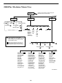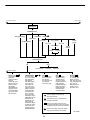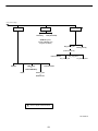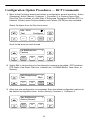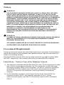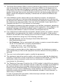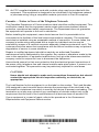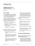
1
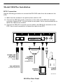
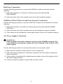
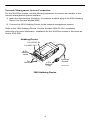
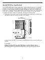
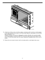
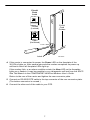
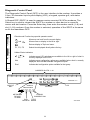
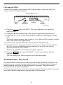
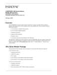
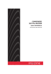
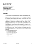
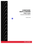
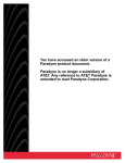
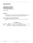
COMSPHERE 3800Plus SERIES MODEMS MODELS 3810Plus and 3811Plus QUICK REFERENCE Document No. 3980-A2-GL10-10 Copyright E 2002 Paradyne Corporation. All rights reserved. Printed in U.S.A. Notice This publication is protected by federal copyright law. No part of this publication may be copied or distributed, transmitted, transcribed, stored in a retrieval system, or translated into any human or computer language in any form or by any means, electronic, mechanical, magnetic, manual or otherwise, or disclosed to third parties without the express written permission of Paradyne Corporation, 8545 126th Ave. N., Largo, FL 33773. Paradyne Corporation makes no representation or warranties with respect to the contents hereof and specifically disclaims any implied warranties of merchantability or fitness for a particular purpose. Further, Paradyne Corporation reserves the right to revise this publication and to make changes from time to time in the contents hereof without obligation of Paradyne Corporation to notify any person of such revision or changes. Changes and enhancements to the product and to the information herein will be documented and issued as a new release to this manual. Warranty, Sales, and Service Information Contact your local sales representative, service representative, or distributor directly for any help needed. For additional information concerning warranty, sales, service, repair, installation, documentation, training, distributor locations, or Paradyne worldwide office locations, use one of the following methods: H Via the Internet: Visit the Paradyne World Wide Web site at www.paradyne.com. H Via Telephone: Call our automated system to receive current information via fax or to speak with a company representative. — Within the U.S.A., call 1-800-870-2221 — Outside the U.S.A., call 1-727-530-2340 Trademarks COMSPHERE is a registered trademark of Paradyne Corporation. All other products and services mentioned herein are the trademarks, service marks, registered trademarks, or registered service marks of their respective owners. Document Feedback We welcome your comments and suggestions about this document. Please mail them to Technical Publications, Paradyne Corporation, 8545 126th Ave. N., Largo, FL 33773, or send e-mail to [email protected]. Include the number and title of this document in your correspondence. Please include your name and phone number if you are willing to provide additional clarification. COMSPHERE 3800Plus Series Modems Models 3810Plus and 3811Plus Quick Reference Document Number 3980-A2-GL10-10 February 2002 Product Documentation on the World Wide Web Complete documentation for this product is available at www.paradyne.com. Select Library → Technical Manuals → Business Class Analog Modems. Select the following document: 3980-A2-GB30 COMSPHERE 3800Plus Series Modems User’s Guide To request a paper copy of a Paradyne document: H Within the U.S.A., call 1-800-PARADYNE (1-800-727-2396) H Outside the U.S.A., call 1-727-530-8623 Before installing your modem, read the Important Safety Instructions on page 23. Package Checklist After opening the modem’s package, check for damage and verify that the following items are present: H 3810Plus modem H Power supply H One 6-position modular cord (in selected models) H One 8-position modular cord (in selected models) 1 Model 3810Plus Installation DTE Connection Use the following procedure to connect the RS-232D cable from the modem to the DTE: 1. Make sure the modem’s rear panel power switch is Off. 2. Connect the DB-25-P (male) connector on the cable to the DB-25-S (female) connector labeled DTE 1 on the modem’s rear panel. Use a small screwdriver to fasten the cable to the modem. 3. Connect the DB-25-P connector on the cable to the DB-25-S connector on the DTE. Use a small screwdriver to fasten the cable to the DTE. DIAL LEASED LEASED-LINE NETWORK 8-POSITION PLUG DIAL NETWORK 6-POSITION PLUG DTE 1 NMS PWR ON OFF DATA TERMINAL EQUIPMENT DB-25-P CONNECTOR SUB-MINIATURE 4-POSITION PLUG FOR NETWORK HUBBING MANAGEMENTDEVICE SYSTEM OPERATION 3810Plus Rear Panel 2 POWER SUPPLY 98-14677-03 Dial-Line Connection Use the following procedure to connect the 3810Plus modem to the dial network interface: 1. Insert the 6-position, 4-conductor modular plug into the jack labeled DIAL/LEASED. 2. Insert the other end of the modular cord into the dial network interface. 3810Plus 4-Wire/2-Wire Leased-Line Network Connection Use the following procedure to connect a 3810Plus modem to the leased-line network interface: 1. Insert the 8-position, 8-conductor modular plug into the jack labeled LEASED (3810Plus). 2. Insert the other end of the modular cord into the leased-line network interface. 3. If you intend to use dial backup, follow steps listed in Dial-Line Connection section. AC Power Supply Connection ! WARNING: Power supplies from other modems may fit into the POWER connector, but connecting the wrong power supply can cause damage to the modem or the power supply. Use the following procedure to connect the modem to an ac power outlet: 1. Make sure the modem’s power switch is in the Off position. 2. Insert the power transformer’s cylindrical connector into the modem’s rear panel power receptacle. 3. If the modem is provided with a tabletop power supply, connect the power cord to the power supply module. 4. Connect the power supply to a grounded ac power outlet. 3 Network Management System Connection For the 3810Plus modem, use the following procedure to connect the modem to the network management system interface: 1. Insert the subminiature 4-position, 4-conductor modular plug of the 3600 Hubbing Device into the jack labeled NMS. 2. Connect the 3600 Hubbing Device to the network management system. Refer to the 3600 Hubbing Device, Feature Number 3600-F3-300, Installation Instructions for more information. Installation for the 3810Plus modem is the same as for the 3610 DSU. Hubbing Device CC OUT/DC IN CC IN/DC OUT E VIC 0 DE 3-30 -F G IN 0 BB 300 HU # 00 EL 30 OD M C C 8-Pin Modular Jacks C /D IN T U O C C C D T/ U O IN 8 1 8 1 Pin Numbers 4-Pin Modular Plug 3600 Hubbing Device 4 6 Inches Overall 496-13775-03 Model 3811Plus Installation The COMSPHERE 3000 Series Carrier has 17 slots which can hold up to 16 modems and one SDU. The SDU is required when the modems in the carrier are controlled by an NMS, or when multiple carriers in a cabinet configuration are to be controlled by a single SDCP. The SDCP of the COMSPHERE 3000 Series Carrier is the user interface to the 3811Plus modem. A single SDCP can control modems in up to eight carriers. To install a 3811Plus modem into the carrier, perform the following steps. 1. At the rear of the carrier, install the rear connector plate. Make sure the plate uses the same slot position as that intended for the modem. V.35 (3600/3500) RS366A/V.25 (3800) EIA232/V.24 25-Pin DTE Connectors P21 496-14906 Loosely fasten the plate. This allows for slight adjustments later when installing the modem. CAUTION: Always use a ground strap when handling a modem. Always store a 3811Plus modem in an antistatic bag when it is removed from the carrier. 5 495-14797 2. At the front of the carrier, hold the modem vertically, with the latch on its faceplate in the open position, and insert it into the top and bottom card guides of one of the slots numbered 1–16. Slide the modem into the slot, aligning the modem with the rear connector plate, until the backplane connector and DTE connector seat firmly into the back of the carrier. To lock the modem into the carrier, press the faceplate latch until a click is heard. 3. Rotate the circuit pack lock(s) into the closed position, and tighten the screw. 6 Circuit Pack Lock Circuit Card Guides Closed (Locked) Open (Unlocked) Latch 495-14813 4. If the carrier is connected to power, the Power LED on the faceplate of the 3811Plus lights up. After several seconds the modem completes its power-up self-test in which all faceplate LEDs light up. If the modem fails, or an alarm condition exists, the Alrm LED on the faceplate lights up or flashes. It may be possible to run a diagnostic self-test from the SDCP. See Test Branch in the COMSPHERE 3800Plus Modems User’s Guide. Return to the rear of the carrier and tighten the rear connector plate. 5. Connect an RS-232D DTE cable to the top connector of the rear connector plate. (The bottom connector is unused.) 6. Connect the other end of the cable to your DTE. 7 Diagnostic Control Panel The Diagnostic Control Panel (DCP) is the user interface to the modem. It provides a 2-line, 32-character liquid crystal display (LCD), a keypad, speaker grill, and status indicators. A Shared DCP (SDCP) is used to manage carrier-mounted 3811Plus modems. The Select key is used to connect the SDCP to a modem or other device in a specific carrier and slot location. Press the Select key, then enter the modem carrier (1–8) and slot (1–16) numbers. Once the modem is selected, operation of the SDCP is the same as for the standalone DCP. Status Direction and Function keys provide operator control. Pwr Alrm 142 Moves up one level from the current display. Test Dial 125 RI Moves cursor or display to the left or right. and Busy Serv Returns display to Top-Level menu. SQ Selects item displayed directly above the key. F1, F2, F3 103 TXD 104 RXD 105 RTS 106 CTS 107 DSR 108 DTR 109 LSD Hidden Choice Indicators. Indicates more LCD selections are available to the left or right of what is currently displayed on the LCD. Front Panel Spkr Nxt Indicates more configuration options are available below what is currently displayed. Also indicates selected configuration option. End Indicates last configuration option available for that group. 3811Plus CARRIER SLOTS 1–16 SDU 1 2 3 4 5 6 7 8 9 10 11 12 13 14 15 16 Select OK SELECT KEY Alarm BckUp Test EC Alarm BckUp Test NETWORK DEVICE ALARM F2 F3 COMSPHERE 3000 LCD STATUS INDICATORS OK F1 KEYPAD EC ERROR CORRECTION DIAL TEST BACKUP MODE 496-14487a 8 Checking the SDCP If an SDCP is installed, verify that the SDCP can be used to control the 3811Plus modem. Perform the following steps. Carrier Slots 1–16 SDU 1 2 3 4 5 6 7 8 9 10 11 12 13 14 15 16 Select OK Select Key Alarm BckUp Test EC Status Indicators F1 F2 F3 Keypad COMSPHERE 3000 LCD Display 496-12348a-03 1. Press the Select key on the SDCP. The cursor appears in the 2-digit slot selection entry. 2. Press the key to position the cursor on the 2-digit carrier selection entry. 3. Press the F1 (↑) or F2 (↓) key until the carrier number you want appears on the LCD. The carrier number selection has a range of 1 to 8. With an SDU installed, a single SDCP can control up to eight carriers. 4. Press the key to position the cursor on the slot selection entry. 5. Press the F1 (↑) or F2 (↓) key until the slot number (1–16) you want appears on the LCD. (Ignore the AB designator that appears on the LCD since it is not applicable to the 3811Plus modem.) The Front Panel LED on the modem’s faceplate lights up. 6. Press the Select key to place the SDCP in direct communication with the selected modem. The LCD displays the Top-Level menu for the selected modem. Administrative Password The Administrative Password is an 8-digit decimal number password that allows only authorized users to access Security branch functions. The Administration Password must be entered every time the Security branch is accessed. The factory default Administration Passsword is 00000000. The Reset_Security function of the Security branch resets the Administrative Password to the value above the bar code on the last page of this reference. 9 3800Plus Modems Menu Tree Displays current status of modem along with data rate and error control mode. “Status” to next page Call_Setup Dial Answer Disconnect Status Test Change_Directory Dial_Standby or Return_to_Dial Directory Locations 1 – 10 VF DTE Identity Ser# No Signal SigQual Mod # RcvLev FRev Sig/Noise HPt# NearEcho FPt# FarEcho FarEchDel EchoFreqOff SDC Options LSD TX RX DTR DSR Tst TXD RXD RTS CTS Record Display Clear Does not appear in Remote Mode. (Rem_Digital_Loop, Loc_Digital_Loop, and Pattern appear if the secondary channel Remote Mode is used.) Some choices within this group may not appear depending upon how previous configuration options have been selected. Abort Self Rem_Digital_Loop Loc_Analog_Loop Pattern Loc_Digital_Loop to next page DTE_Interface Async/Sync Mode Async DTE Rate Sync DTE Rate #Data Bits Parity Bit #Stop Bits DTR Action DSR Control RTS Action CTS Control RTS/CTS Delay LSD Control TX Clock Source CT111_Rate Cntl DTE_Rate = VF DTE_Dialer DTE Dialer Type AT Escape Char Escape GuardTim BreakForceEscap CommandCharEcho CarriageRtn Char Backspace Char Linefeed Char Result Codes ExtendResltCode ResultCode Form V25bis Coding V25bis IdleFill V.25b NewLineChr AT Cmnd Mode DTR Cont Repeat Line_Dialer AutoAnswerRing# Dialer Type DialTone Detect Blind Dial Paus BusyTone Detect "," Pause Time NoAnswer Timout Fast Disconnect Long Space Disc No Carrier Disc No Data Disc NoDataDiscTrig Auto Make Busy MakeBusyViaDTR DTR Auto Redial MI/MIC Dialing Dial_Line Modulation Dial Line Rate Automode Autorate Dial TX Level V22b Guard Tone Train Time Asymmetric Rate Proactive Retrain Fall Fwd Delay 98-15990a-01 10 from previous page to next page Configure Ld EditArea frm: Activ (Operating) Customer2 Factory Customer1 Async_Dial Active (Saved) Sync_Leased Sync_Dial Cellular (PSTN) UNIX_Dial Choose Mode Answer Cellular (Mobile) Originate Choose Function Edit Save Active (Saved) Customer1 Customer2 from previous page Leased_Line Leased Mode Modulation LeasedLine Rate Autorate Leased TX Level Bad Ln Auto Orig Rate Auto Orig Auto Redial AutoDialStandby CarrierOn Level V.29 TrainOnData Asymmetric Rate Fall Fwd Delay V42/MNP/Buffer Err Contrl Mode Sync Comp Mode SDC Negotiation SDC Idle Fill SDC BitEncoding SyncDTE CRC SDC Delay Min Sync Flow Cntrl V42bis Compress MNP5 Compress EC Negotiat Bfr EC Fallbck Char Flw Cntl of DTE Flw Cntl of Mdm XON/XOFF Psthru Mdm/Mdm FlowCtl Break Buffr Ctl Send Break Cntl [SDC Options] Tx Buff Disc Delay Rx Buff Disc Delay Max Frame Size Cellular Enhance BfrSizeInBfrMode Test DTE RL (CT140) DTE LL (CT141) Test Timeout Rcv Remote Loop V54 Address V54 Device Type Misc StrapsWhenDisc Speaker Control Speaker Volume Access frm Remt RemAccssPasswrd Dir#1_Callback NetMngmtAddress NMS_Call_Msgs NMS DTR Alarm NetworkPosition CellulrRJ11Adpt Security EntryWait_Time VF_Prompt_Type #DTE_PW_Tries DTE_PW_TermChar DTE_PW_BkSpChar Get_User_ID NMS_Reporting Answer_Secur Originate_Secur Does not appear if configured for Synchronous mode Only appears if Sync_Leased factory template is selected. Some choices within this group may not appear depending upon how previous configuration options have been selected. Some choices within this group appear only if optional features are installed. 11 98-15990b from previous page Control Remote Secondary Security ▲ Prim (data blckd) (ExitRem appears instead of Remote when using Remote Mode) Set_Access_Ctrl Reset_Security (Admin Password?) EditPassWdTable Set_Orig_Secur Set_Answer_Sec Speaker Make_Busy or RemoveMakeBusy Reset Set_Admin_PsWd Download Code Service_Line or DiscServLine ▲ Does not appear in Remote Mode. 98-15990c-01 12 Configuration Option Procedures — DCP Commands 1. Move to the Configure branch and select a configuration area to load from: Active (Operating), Active (Saved), Customer 1, Customer 2, or Factory (Async Dial, Sync Dial, Sync Leased, or UNIX Dial). If Enhanced Throughput Cellular (ETC) is installed, Factory areas Cellular (Mobile) and Cellular (PSTN) are also available. Select Configure from the Top-Level menu. Idle : 28.8 Test F1 Configure F2 F3 Scroll to the area you wish to load. Ld EditArea frm Factory F1 F2 < F3 2. Select Edit to choose the set of configuration options to be edited: DTE Interface, DTE Dialer, Line Dialer, Dial Line, Leased Line, V.42/MNP/Buffer, Tests, Misc, or Security. Edit StrapGroup < Test Misc F1 F2 F3 3. When the new configuration is completed, Save the edited configuration options to the desired configuration area: Active (Saved), Customer 1, Customer 2. Sav EditArea to Active (Saved) F1 F2 > F3 13 Configuration Option Procedures — AT Commands Loading Factory Configurations Use the AT&Fy&Wn command to load a factory configuration to either the Active (Saved), Customer 1, or Customer 2 configuration area. Type: AT&Fy&Wn where: y is one of the following factory configurations: 0 = Async Dial 1 = Sync Dial 2 = Sync Leased (Answer) 3 = UNIX Dial 4 = Sync Leased (Originate) 5 = Cellular (Mobile) (if ETC installed) 6 = Cellular (PSTN) (if ETC installed) where: n is one of the following configuration areas: 0 = Active (Saved) 1 = Customer 1 2 = Customer 2 Loading Configuration Areas to Active (Operating) Use the ATZn command to load stored configurations from Active (Saved), Customer 1, or Customer 2 configuration areas to Active (Operating). Type: ATZn where: n is one of the following: 0 = Active (Saved) 1 = Customer 1 2 = Customer 2 3 = Active (Saved) + Reset 14 AT COMMANDS AT COMMANDS (continued) Bold text indicates Async Dial factory defaults. Mn M0 M1 AT A/ A Attention Command Prefix/Autobaud Rate. Indicates a command string has started and determines the DTE’s data rate and parity. M2 Repeat Last Command. Reexecutes last command string. (Not to be preceded with AT or followed by pressing the Return key.) Answer Mode. Goes off-hook and attempts to establish a connection without waiting for a ring. B0 B1 ITU-T V.21 or V.22 (300 or 1200 bps) Bell 103 or 212A (300 or 1200 bps) Dn Dial. Dials the telephone number n with optional modifiers: T P , W R @ ! ; DS=n Dial Stored Number. Dials the number stored in location n (1–10). En E0 E1 Command Character Echo Disables echo to the DTE. Enables echo to the DTE. H0 H1 Modem goes on-hook. Modem goes off-hook. I0 I1 I11 I19 Displays product code–144. Displays 3-digit firmware revision number. Performs an EPROM check. Displays modem’s serial number. Displays modem’s model number. Displays part number of circuit card. Displays firmware release number. (same as I1) Changes value of product code (0=144, 1=240, 2=480, 3=960, 4=120). Firmware checksum. Displays entire firmware revision number. Ln L0,L1 L2 L3 Speaker Volume Selects low volume. Selects medium volume. Selects high volume. O Returns modem to Data mode from online Command mode. P Enables Pulse Dial mode. Qn Q0 Result Codes Enables result codes. Refer to Result Codes section. Disables result codes. Enables originate modem to send result codes to the DTE. Required for most UNIX applications. Q1 Q2 Sn? Sn=r Tone Dial (DTMF) Pulse Dial Pause Wait for Dial Tone Reverse Dial Quiet Answer Hook Flash Return to Command Mode Enables Tone Dial mode. Vn V0 V1 V2 Result Code Format Displays as digits (Numbers 1). Displays as text. Displays as digits (Numbers 2). Xn Extended Result Codes; Dial Tone Detect; Busy Tone Detect Disables extended result codes 5–16, dial tone detect, and busy tone. Enables extended result codes 5–16, disables dial tone detect and busy tone detect. Refer to Result Codes section. Enables extended result codes 5–16, dial tone detect, and disables busy tone detect. Enables extended result codes 5–16, disables dial tone detect and enables busy tone detect. Refer to Result Codes section. Enables extended result codes 5–16, dial tone detect, and busy tone detect. Refer to Result Codes section. Adds EC suffix to extended result codes (20–27) if error control is used, enables dial tone detect and busy tone detect. Adds either V.42 or MNP suffix to extended result codes (20–27) if data compression is used, enables dial tone detect, and busy tone detect. DTE rate appears in CONNECT message instead of line rate, enables dial tone detect and busy tone detect. Refer to Result Codes section. X0 X1 X3 X4 X5 X6 X7 15 Displays value of S-Register (where n is the register number). Change S-Register. Changes the contents of the S-Register (where n is the register number and r is the assigned value). T X2 I2 I3 I4 I5 I6 I9 I10=n Speaker ON/Off Control Speaker always Off. Speaker ON until carrier signal becomes active. Speaker always ON. AT COMMANDS (continued) AT COMMANDS (continued) Yn Y0 Y1 Long Space Disconnect Disable. Enable. &Fn &F0 Zn Z0 Reset and Load Active Loads contents of Active (Saved) into Active (Operating). Loads contents of Customer 1 into Active (Operating). Loads contents of Customer 2 into Active (Operating). Loads contents of Active (Saved) into Active (Operating) and performs a reset. Performs a full modem reset. &F1 Z1 Z2 Z3 Z9 +FCLASS=n +FCLASS=0 +FCLASS=1 +FCLASS=2 &Cn &C0 &C1 &C2 &C3 &C4 &C5 &C6 &Dn &D0 &D1 &D2 &D3 &D4 &F5 &F6 Loads Factory Configuration Loads Async Dial factory configuration options into Active (Operating) configuration area. Loads Sync Dial factory configuration options into Active (Operating) configuration area. Loads Sync Leased (Answer Mode) factory configuration options into Active (Operating) configuration area. Loads UNIX Dial factory configuration options into Active (Operating) configuration area. Loads Sync Leased (Originate Mode) factory configuration options into Active (Operating) configuration area. Cellular (Mobile) (if ETC installed). Cellular (PSTN) (if ETC installed). &Gn &G0 &G1 &G2 V.22bis Guard Tone Disables guard tone. Sets guard tone to 550 Hz. Sets guard tone to 1800 Hz. &In &I10 &I11 • • &I32 &I99 &I100 Dial Transmit Level –10 dBm. –11 dBm. • • –32 dBm. ETC 1.0 (if ETC installed). ETC 1.1 (if ETC installed). &Jn &J0 Dial Transmit Level Type Modem sets dial transmit level to Permissive mode at –9 dBm. &Ln &L0 &L1 &L2 &L3 &L4 Leased-Line Mode Disables leased-line operation. 2-wire originate leased-line operation. 4-wire originate leased-line operation. 2-wire answer leased-line operation. 4-wire answer leased-line operation. &F2 &F3 &F4 Fax class Data Fax Class 1 (EIA 578) Fax Class 2 (EIA/TIA SP-2388) LSD Control Forced On. Forces LSD ON at all times. Standard RS232. LSD is ON when the remote modem’s carrier signal is detected. LSD is Off when carrier signal is not detected. Wink When Disc. LSD, normally forced ON, turns Off for approximately 1 to 2 seconds upon disconnect. Follows DTR. State of LSD follows state of DTR. Simulated Control Carrier. State of LSD follows state of remote modem’s RTS. =DTR/DiscOff. State of LSD follows state of DTR except upon a disconnect where DTR remains ON and LSD turns Off. DTR must then toggle Off and ON to turn LSD ON. Required for AT&T DATAKIT dial-out applications. Bridge Retrain. LSD behaves as in Standard RS232, except that it is turned Off when retrain lasts longer than 10 seconds, and ON when no retrain is detected for 10 seconds. &Mn,&Qn Async/Sync Mode and DTE Dialer Type &M0,&Q0 Modem operates in Async mode and uses AT command protocol. &M1,&Q1 Modem operates in Sync mode and uses AT command protocol. &M2,&Q2 Modem operates in Sync mode and dials the number stored in directory location 1 when DTR signal turns Off and then ON. &M3,&Q3 Modem operates in Sync mode and uses AT command protocol. &Q4 Modem operates in Async mode and uses AT Command protocol; Hayes AutoSync is enabled. &M6,&Q6 Modem operates in Sync mode and dials the number stored in directory location 1 when DTR signal turns Off and then ON and leased line is down. &M231, &Q231 Modem operates in Async mode; the DTE Dialer Type is disabled. DTR Action Ignore. Modem ignores the DTR (Data Terminal Ready) signal and treats it as always ON. Off=Command Mode. Modem enters online Command mode when DTR is lowered. Standard RS232. DTR signal is controlled by the DTE. Off=Reload Straps. Modem loads Active (Operating) area with Active (Saved) area when DTR is lowered. Controls On-Hook. Modem does not disconnect until DTR lowered by DTE. 16 AT COMMANDS (continued) AT COMMANDS (continued) &M232, &Q232 Modem operates in Async mode; V.25bis Async dialing is enabled. &M233, &Q233 Modem operates in Sync mode; V.25 Bisync dialing is enabled. &M234, &Q234 Modem operates in Sync mode; V.25bis HDLC dialing is enabled. &M235, &Q235 Modem operates in Async mode; AT&T Exclusive dialing is enabled. &M236, &Q236 Modem operates in Sync mode; the DTE Dialer Type is disabled. &Vn &V0 &Rn &R0 &R1 &R2 &R3 &Sn &S0 &S1 &S2 &S3 &S4 &S5 &S6 &Tn &T0 &T1 &T2 &T3 &T4 &T5 &T6 &T7 &T8 &T9 &V1 &V2 &V3 &V4 RTS Action Standard RS232. RTS action is controlled by DTE. Ignores RTS. Modem ignores RTS signal and treats it as always ON. Simulated Control Carrier. State of RTS follows state of LSD. Control Carrier. DTE’s RTS signal controls modem’s carrier signal. &Wn &W0 &W1 &W2 &Xn &X0 DSR Control Forced On. Forces DSR signal ON. Standard RS232. Modem controls DSR signal. Wink When Disc. DSR signal turns Off for approximately 1 to 2 seconds upon disconnecting. Follows DTR. Modem sends DSR to DTE when it receives DTR from DTE. On Early. DSR is Off when modem is in idle state. DSR goes ON when modem enters Data mode. Delay to Data. DSR does not turn ON until the modem enters Data mode. Dial Backup toggle. &X1 &X2 Tests Stops any test in progress. Starts a Local Analog Loopback test (V.54, L3). Transmits and receives a 511 BERT pattern. Starts a Local Digital Loopback test. Accepts request from remote modem for a Remote Digital Loopback test. Denies request from remote modem for a Remote Digital Loopback test. Starts a Remote Digital Loopback test (V.54, type L2). Starts a Remote Digital Loopback test with a Pattern (V.54, type L2). Starts a Local Analog Loopback test with a Pattern (V.54, type L3). Starts a self-test. Write (Save to Memory) Saves current configuration options in Active (Operating) to Active (Saved). Saves current configuration options in Active (Operating) to Customer 1. Saves current configuration options in Active (Operating) to Customer 2. Transmit Clock Source Modem provides internal clock source for synchronous data (Pin 15). Modem uses external source (Pin 24) for clock for synchronous data. Modem uses received signal as clock source for synchronous data. &Zn=x Modem stores telephone number x (and any dial modifiers) in directory location n (1–10). For example, the command AT&Z1=555-1234 stores the number 5551234 in directory location 1. To clear a telephone number from a memory location, issue &Zn=x without entering a telephone number. \An \A0 \A1 \A2 \A3 \A4 \A5 Maximum Frame Size 64 128 192 256 32 16 \Cn \C0 Error Control Negotiate Buffer Data is not buffered during handshaking sequence. Data is buffered up to 4 seconds during handshaking sequence. Data is not buffered during handshaking sequence; however, the modem switches to Buffer mode when it receives an error control fallback character. \C1 \C2 17 View Configuration Options Displays Active (Operating) configuration options. Displays Active (Saved) configuration options. Displays Customer 1 configuration options. Displays Customer 2 configuration options. Displays telephone numbers stored in directory locations 1–10. AT COMMANDS (continued) AT COMMANDS (continued) \Dn \D0 \D1 \D2 \Tn \T0 \Tn No Data Disconnect Timer Disables no data disconnect timer. Sets no data disconnect timer to a value from 1 minute to 255 minutes. \Xn \X0 XON/XOFF Passthrough Disables transmission of flow control characters to remote modem. Enables transmission of flow control characters to remote modem. \D3 CTS Control Forced On. CTS is forced ON. Standard RS232 operation. Wink When Disc. CTS turns Off for approximately 1 to 2 seconds upon disconnecting. Follows DTR. The state of CTS follows the state of DTR. \X1 \Gn \G0 \G1 \Kn \K0 \K1 \K2 \K3 \K4 \K5 \K6 \Nn \N0 \N1 \N2 \N3 \N4 \N5 \N6 \N7 Modem-to-Modem Flow Control Disables modem-to-modem flow control. Enables modem-to-modem flow control. Break Buffer Control, Send Break Control, Break Forces Escape Discards data, sends break before data, and enables break forces escape. Discards data, sends break before data, and disables break forces escape. Keeps data, sends break before data, and enables break forces escape. Keeps data, sends break before data, and disables break forces escape. Keeps data, sends data before break, and enables break forces escape. Keeps data, sends data before break, and disables break forces escape. Discards break, disables break forces escape. %An Sets error control fallback character n to an ASCII value from 0 to 127. %Bn Sets modulation to V.34 and VF rate to n (300, 1200, or 2400 to 33600 in increments of 2400). Default is %B33600. Sets modulation to V.32bis and VF rate to n (2400 to 19200 in increments of 2400) %BLn Error Control Mode Buffer Mode. Modem does not use error control; DTE rate can differ from VF rate. Direct Mode. Modem does not use error control; DTE rate and VF rate must be the same. MNP or Disc. Modem disconnects if it does not connect in MNP mode. MNP or Buffer. Modem connects in Buffer mode if it does not connect in MNP mode. V.42/MNP or Disc. Modem disconnects if it does not connect in V.42 or MNP mode. V.42/MNP or Buffer. Modem connects in Buffer mode if it does not connect in V.42 or MNP mode. LAPM or disconnect. LAPM or buffer. %Cn %C0 %C1 MNP 5 Data Compression Disables MNP5 data compression. Enables MNP5 data compression. %Rn Sets DTE rate for Asynchronous mode to n (300, 1200, 2400, 4800, 7200, 9600, 12000, 14400, 19200, 28800, 38400, 57600, 76800, or 115200). #DMn #DM0 #DM1 SDC Delay Minimization Only whole frames transmitted to DTE. Partial frames transmitted to DTE as received. #Qn #Q0 #Q1 #Q2 Sync Flow Ctrl No flow control. Flow control using TX clock. Flow control using CTS. #SCn #SC0 #SC1 Sync Comp Mode Disable SDC. Enable SDC. IHn IH0 IH1 V.42 bis Data Compression Disables V.42 bis data compression. Enables V.42 bis data compression for transmit only. Enables V.42 bis data compression for receive only. Enables V.42 bis data compression in both the transmit and receive directions. IH2 IH3 \Qn Flow Control of DTE \Q0, \Q5, \Q6 Disables flow control of DTE. \Q1, \Q4 Enables XON/XOFF flow control. \Q2, \Q3 Modem raises and lowers CTS to start and stop flow control. ILn IL0 IL1 \Qn Flow Control of Modem \Q0, \Q2, \Q4 Disables flow control of modem. \Q1, \Q5 Enables XON/XOFF flow control. \Q3, \Q6 Modem starts and stops flow control based upon state of DTE’s RTS signal. 18 Disconnect at 300 bps Disable Enable RESULT CODES DIAL COMMAND MODIFIERS Numbers(1) Numbers(2) Words 0 0 OK 1 1 CONNECT 2 2 RING 3 3 NO CARRIER 4 4 ERROR T P , W R @ ! ; Result Codes 5–14, 16, 19 are enabled with the X1, X2, X3, and X4 commands. 5 5 CONNECT 1200 6 6 NO DIALTONE 7 7 BUSY 8 8 NO ANSWER 10 10 CONNECT 2400 11 11 CONNECT 4800 12 12 CONNECT 9600 13 16 CONNECT 12000 14 13 CONNECT 14400 15 14 CONNECT 19200 16 15 CONNECT 7200 17 17 CONNECT 16800 19 1 CONNECT 300 Result Codes 20–27, 29, and 37–48 are enabled with the X5 command (EC suffix) or the X6 command (V.42 or MNP suffix). 20 10 CONNECT 2400/EC 21 11 CONNECT 4800/EC 22 12 CONNECT 9600/EC 23 16 CONNECT 12000/EC 24 13 CONNECT 14400/EC 25 17 CONNECT 16800/EC 26 15 CONNECT 7200/EC 27 5 CONNECT 1200/EC 29 14 CONNECT 19200/EC 37 37 CONNECT 21600 38 38 CONNECT 24000 39 39 CONNECT 26400 40 40 CONNECT 28800 41 41 CONNECT 31200 42 42 CONNECT 33600 43 43 CONNECT 21600/EC 44 44 CONNECT 24000/EC 45 45 CONNECT 26400/EC 46 46 CONNECT 28800/EC 47 47 CONNECT 31200/EC 48 48 CONNECT 33600/EC Result Codes 15, 28–34 are enabled with the X7 command (DTE rate suffix). 28 28 CONNECT 38400 30 30 CONNECT 57600 32 32 CONNECT 76800 34 34 CONNECT 115200 19 Tone Dial (DTMF) Pulse Dial Pause Wait for Dial Tone Reverse Dial Quiet Answer Hook Flash Return to Command Mode S-REGISTERS Register Description Factory Setting 1 Range S0 Auto-Answer Ring Number 0(Disable) or 1–255 rings S2 AT Escape Character 43(+) 0–127 ASCII S3 Carriage Return Character 13 0–127 ASCII S4 Line Feed Character 10 0–127 ASCII S5 Backspace Character 8 0–127 ASCII S6 Blind Dial Pause 2 2–255 seconds S7 No Answer Time-out S8 45 1–255 seconds “,” Pause Time for the Dial Modifier 2 0–255 seconds S10 No Carrier Disconnect 2 0–254 (10ths of a second) or 255(Disable) S12 Escape Sequence Guard Time S14 Asymmetric Rate (Dial) 0 0=Enable; 1=Disable S15 Asymmetric Rate (Leased) 0 0=Enable; 1=Disable S18 Test Time-out S23 Proactive Retrain S25 AutoSync Start Pause S26 RTS/CTS Delay 0 0–255 seconds S28 SDC Negotiation 0 0=LAPM_Buffer; 1=LAPM_Discon S29 SDC Idle Fill 0 0=Flag_Fill; 1=Mark_Fill S30 Sync DTE Rate 0 0=12800 bps; 1=115200; 3=96000; 4=78800; 5=72000; 6=64000; 7=57600; 8=56000; 9=48000; 10=38400; 11=28800; 12=19200; 13=14400; 14=9600; 15=4800; 16=2400; 17=1200 S31 SDC Bit Encoding 0 0=NRZ; 1=NRZI S32 Sync DTE CRC 0 0=Ignore; 1=CRC16 S33 Buffer Size In Buffer Mode 0 0=Normal; 1=Minimized S35 Auto Redial 0 0=Dir1; 1=Dirs1–2; 2=Dirs1–3... 9=Dirs1–10 S36 Rate Auto Originate 0 0(Disable) or 1(4800) – 6(16,800) S37 Auto Redial 0 0(Dir 1) – 9(Dirs 1–10) S38 DTR Cont Repeat 0 0=Disable, 1=Enable S39 RX Buffer Disconnect Delay 0 0(Disable) or 1–255 seconds S40 Auto Make Busy 0 0=Disable, 1=Enable S41 Dial Line Rate 50 0(disabled) 0 0(disabled) 29 20 0–255 in 20-millisecond increments 0–255 seconds 0=Enable; 1=Disable 0–30 seconds 1=14400(V.32bis); 2=12000(V.32bis); 3=9600(V.32bis); 4=7200(V.32bis); 5=4800(V.32bis); 6=2400(V.22bis); 7=1200(V.22); 8=1200(212A); 10=0–300(V.21); 11=0–300(103J); 20=19200(V.32terbo); 21=16800(V.32terbo); 27=33600(V.34); 28=31200(V.34); 29=28800(V.34); 30=26400(V.34); 31=24000(V.34); 32=21600(V.34); 33=19200(V.34); 34=16800(V.34); 35=14400(V.34); 36=12000(V.34); 37=9600(V.34); 38=7200(V.34); 39=4800(V.34); 40=2400(V.34) S-REGISTERS (continued) Register Description Factory Setting 0 Range S43 Train Time S44 Leased-Line Rate S45 Leased TX Level 0 0dBm–15dBm S46 Auto Dial Backup 0 0=Disable; 1=Enable S47 Auto Dial Standby 0 0=Disable; 1=15 minutes; 2=1 hour; 3=4 hours; 255=Test(2min) S48 Leased-Line Carrier On Level 0 0=–43dBm; 1=–26dBm 27 10 0=Long; 1=Short 1=14400(V.32bis); 2=12000(V.32bis); 3=9600(V.32bis); 4=7200(V.32bis); 5=4800(V.32bis); 6=2400(V22bis); 18=19200(V.32terbo); 19=16800(V.32terbo); 25=33600(V.34); 26=31200(V.34); 27=28800(V.34); 28=26400(V.34); 29=24000(V.34); 30=21600(V.34); 31=19200(V.34); 32=16800(V.34); 33=14400(V.34); 34=12000(V.34); 35=9600(V.34); 36=7200(V.34); 37=4800(V.34); 38=2400(V.34) S49 Buffer Disconnect Delay S51 DTE RL (CT140) 0 0=Disable or 1–255 in 1-second increments 0=Disable; 1=Enable S52 DTE LL (CT141) 0 0=Disable; 1=Enable S53 V.54 Address 0 0(Disable) or 1–34 S54 V.54 Device Type 0 0=Peripheral; 1=Intermediate S55 Access from Remote 0 0=Enable; 1=Disable S56 Remote Access Password 1st and 2nd digits 00 00–99 S57 Remote Access Password 3rd and 4th digits 00 00–99 S58 Remote Access Password 5th and 6th digits 00 00–99 S59 Remote Access Password 7th and 8th digits 00 00–99 S61 CT111 Rate Control S62 V.25bis Coding 0 0=ASCII; 1=EBCDIC S63 V.25bis Idle Character 0 0=Mark; 1=Flag S64 V.25bis New Line Character 0 0=CR+LF; 1=CR; 2=LF S66 NMS Call Messages 0 0=Call Connect & Progress; 1=Disable; 2=Call Connect Only; 3=Call Progress Only S67 Directory Location 1 Callback 0 0=Disable; 1=Enable S69 Make Busy Via DTR 0 0=Disable; 1=Enable S74 Network Position 0 0=Tributary; 1=Control S75 Network Management Address S76 Dial Autorate 0 255 0 21 0=Ignore; 1=Fallback 1; 2=Fallback 2 0–255 (001–256) 0=Enable; 1=Disable; 2=Start at 4800; 3=Start at 9600 S-REGISTERS (continued) Register Description Factory Setting Range S77 DTR Alarm Reporting 0 S78 Dial Automode 0 0=Enable; 1=Disable; 2=System85 S80 No Data Disc Trigger Signal 3 0=RX or TX; 1=TX; 2=RX; 3=TX and RX S82 Leased Autorate 0 0=Enable; 1=Disable S83 MI/MIC Dialing 0 0=Disable; 1=Enable S84 AT Command Mode 0 0=Normal; 1=No Error; 2=No Strap or ERROR S85 Fast Disconnect 0 0=Disable; 1=Enable S88 Straps When Disconnected 0 0=No Change; 1=Reload; 2=Reload, No Change S89 V.42 ARQ Window Size Increase 0 0(6 frames) – 9(15 frames) S90 DTE Rate = VF Rate 0 0=Disable; 1=Enable S91 Cellular Enhancement (if ETC installed) 0 0=Disable; 1=Enable S92 V.29 Train On Data (if V.29 installed) 0 0=Disable; 1=Enable S93 RJ11 Cellular Adapt (if ETC installed) 0 0=Disable; 1=Enable 22 0=Disable; 1=Enable Important Safety Instructions 1. Read and follow all warning notices and instructions marked on the product or included in the manual. 2. Slots and openings in the cabinet are provided for ventilation. To ensure reliable operation of the product and to protect it from overheating, these slots and openings must not be blocked or covered. 3. Do not allow anything to rest on the power cord and do not locate the product where persons will walk on the power cord. 4. Do not attempt to service this product yourself, as opening or removing covers may expose you to dangerous high voltage points or other risks. Refer all servicing to qualified service personnel. 5. General purpose cables are used with this product for connection to the network. Special cables, which may be required by the regulatory inspection authority for the installation site, are the responsibility of the customer. 6. When installed in the final configuration, the product must comply with the applicable Safety Standards and regulatory requirements of the country in which it is installed. If necessary, consult with the appropriate regulatory agencies and inspection authorities to ensure compliance. 7. A rare phenomenon can create a voltage potential between the earth grounds of two or more buildings. If products installed in separate buildings are interconnected, the voltage potential may cause a hazardous condition. Consult a qualified electrical consultant to determine whether or not this phenomenon exists and, if necessary, implement corrective action prior to interconnecting the products. 8. Input power to this product must be provided by one of the following: (1) a UL Listed/CSA certified power source with a Class 2 or Limited Power Source (LPS) output for use in North America, or (2) a certified transformer, with a Safety Extra Low Voltage (SELV) output having a maximum of 240 VA available, for use in the country of installation. 9. In addition, since the equipment is to be used with telecommunications circuits, take the following precautions: — Never install telephone wiring during a lightning storm. — Never install telephone jacks in wet locations unless the jack is specifically designed for wet locations. — Never touch uninsulated telephone wires or terminals unless the telephone line has been disconnected at the network interface. — Use caution when installing or modifying telephone lines. — Avoid using a telephone (other than a cordless type) during an electrical storm. There may be a remote risk of electric shock from lightning. — Do not use the telephone to report a gas leak in the vicinity of the leak. 23 Notices ! WARNING: THIS EQUIPMENT HAS BEEN TESTED AND FOUND TO COMPLY WITH THE LIMITS FOR A CLASS A DIGITAL DEVICE, PURSUANT TO PART 15 OF THE FCC RULES. THESE LIMITS ARE DESIGNED TO PROVIDE REASONABLE PROTECTION AGAINST HARMFUL INTERFERENCE WHEN THE EQUIPMENT IS OPERATED IN A COMMERCIAL ENVIRONMENT. THIS EQUIPMENT GENERATES, USES, AND CAN RADIATE RADIO FREQUENCY ENERGY AND, IF NOT INSTALLED AND USED IN ACCORDANCE WITH THE INSTRUCTION MANUAL, MAY CAUSE HARMFUL INTERFERENCE TO RADIO COMMUNICATIONS. OPERATION OF THIS EQUIPMENT IN A RESIDENTIAL AREA IS LIKELY TO CAUSE HARMFUL INTERFERENCE IN WHICH CASE THE USER WILL BE REQUIRED TO CORRECT THE INTERFERENCE AT HIS OWN EXPENSE.THE AUTHORITY TO OPERATE THIS EQUIPMENT IS CONDITIONED BY THE REQUIREMENTS THAT NO MODIFICATIONS WILL BE MADE TO THE EQUIPMENT UNLESS THE CHANGES OR MODIFICATIONS ARE EXPRESSLY APPROVED BY PARADYNE. ! WARNING: TO USERS OF DIGITAL APPARATUS IN CANADA:THIS CLASS A DIGITAL APPARATUS MEETS ALL REQUIREMENTS OF THE CANADIAN INTERFERENCEĆCAUSING EQUIPMENT REGULATIONS. CET APPAREIL NUMÉRIQUE DE LA CLASSE A RESPECTE TOUTES LES EXIGENCES DU RÈGLEMENT SUR LE MATÉRIEL BROUILLEUR DU CANADA. Government Requirements Certain governments require that instructions pertaining to connection to the telephone network be included in the installation and operation manual. Specific instructions are listed in the following sections. Note that 3810Plus and 3811Plus are the model names for the model numbers 3980 and 3981, respectively. The modems collectively are called 3800Plus modems. United States – Notice to Users of the Telephone Network 1. This equipment complies with Part 68 of the FCC rules. On the equipment is a label that contains, among other information, the FCC registration number and ringer equivalence number (REN) for this equipment. The label is located on the bottom of the Model 3810Plus modem and on the circuit card assembly of the Model 3811Plus. If requested, this information must be provided to the telephone company. 2. For the standalone modems, the Universal Service Order Code (USOC) for Permissive mode is RJ11C; the Canadian equivalent is CA11. For the carrier-mounted modem, the USOC for Permissive mode is RJ21X (Canadian CA21A). 24 3. The Ringer Equivalence (REN) is used to determine the quantity of devices which may be connected to the telephone line. Excessive RENs on the telephone line may result in the devices not ringing in response to an incoming call. In most, but not all areas, the sum of the RENs should not exceed five (5.0). To be certain of the number of devices that may be connected to the line, as determined by the total RENs, contact the telephone company to determine the maximum RENs for the calling area. 4. If the 3800Plus modem causes harm to the telephone network, the telephone company will notify you in advance that temporary discontinuance of service may be required. But if advance notice is not practical, the telephone company will notify the customer as soon as possible. Also, you will be advised of your right to file a complaint with the FCC if you believe it is necessary. 5. The telephone company may make changes in its facilities, equipment, operations, or procedures that could affect the operation of the equipment. If this happens, the telephone company will provide advance notice in order for you to make the necessary modifications in order to maintain uninterrupted service. 6. If you experience trouble with this equipment, please contact your sales or service representative (as appropriate) for repair or warranty information. If the product needs to be returned to the company service center for repair, contact them directly for return instructions using one of the following methods: — Via the Internet: Visit the Paradyne World Wide Web site at http://www.paradyne.com — Via Telephone: Call our automated call system to receive current information via fax or to speak with a company representative. — Within the U.S.A., call 1-800-870-2221 — Outside the U.S.A., call 1-727-530-2340 If the trouble is causing harm to the telephone network, the telephone company may request that you remove the equipment from the network until the problem is resolved. 7. The user is not authorized to repair or modify the equipment. 8. This equipment cannot be used on public coin service provided by the telephone company. Connection to Party Line Service is subject to state tariffs. (Contact the state public utility commission, public service commission or corporation commission for information.) 9. The Telephone Consumer Protection Act of 1991 makes it unlawful for any person to use a computer or other electronic device to send any message via a telephone fax machine unless such a message clearly contains, in a margin at the top or bottom of each transmitted page, or on the first page of the transmission, the date and time it is sent, and an identification of the business, or other entity, or other individual sending the message, and the telephone number of such business, or other entity, or individual. In order to program this information, follow the steps outlined in the manual supplied with your fax software. 25 10. An FCC compliant telephone cord with modular plugs may be provided with this equipment. This equipment is designed to be connected to the telephone network or premises wiring using a compatible modular jack which is Part 68 compliant. Canada — Notice to Users of the Telephone Network The Canadian Department of Communications label identifies certified equipment. This certification means that the equipment meets certain telecommunications network protective, operational and safety requirements. The Department does not guarantee the equipment will operate to the user’s satisfaction. Before installing this equipment, users should ensure that it is permissible to be connected to the facilities of the local telecommunications company. The equipment must also be installed using an acceptable method of connection. In some cases, the company’s inside wiring associated with a single line individual service may be extended by means of a certified connector assembly (telephone extension cord). The customer should be aware that compliance with the above conditions may not prevent degradation of service in some situations. Repairs to certified equipment should be made by an authorized Canadian maintenance facility designated by the supplier. Any repairs or alterations made by the user to this equipment, or equipment malfunctions, may give the telecommunications company cause to request the user to disconnect the equipment. Users should ensure for their own protection that the electrical ground connections of the power utility, telephone line and internal metallic water pipe system, if present, are connected together. This precaution may be particularly important in rural areas. CAUTION: Users should not attempt to make such connections themselves, but should contact the appropriate electric inspection authority, or electrician, as appropriate. The Load Number for this equipment is on the label on the modem. The Load Number (LN) assigned to each terminal device denotes the percentage of the total load to be connected to a telephone loop which is used by the device to prevent overloading. The termination on a loop may consist of any combination of devices subject only to the requirement that the total of the Load Numbers of all devices does not exceed 100. If your equipment is in need of repair, refer to the procedure in the Government Requirements and Equipment Return section. 00282600 *3980-A2-GL10-10* *3980–A2–GL10–10* 26