1
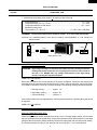
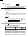
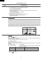
R-3S68
SERVICE MANUAL
S3612R3S68PX/
MICROWAVE OVEN
MODEL
R-3S68
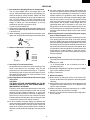
In interests of user-safety the oven should be restored to its original
condition and only parts identical to those specified should be used.
TABLE OF CONTENTS
Page
CAUTION, MICROWAVE RADIATION ................................................................................................................. 1
WARNING .............................................................................................................................................................. 1
PRODUCT SPECIFICATIONS ............................................................................................................................. 2
GENERAL INFORMATION .................................................................................................................................... 2
APPEARANCE VIEW ........................................................................................................................................... 3
OPERATION SEQUENCE .................................................................................................................................... 4
FUNCTION OF IMPORTANT COMPONENTS ..................................................................................................... 5
SERVICING .......................................................................................................................................................... 6
TEST PROCEDURE ............................................................................................................................................. 8
TOUCH CONTROL PANEL ................................................................................................................................. 14
COMPONENT REPLACEMENT AND ADJUSTMENT PROCEDURE ............................................................... 18
MICROWAVE MEASUREMENT ........................................................................................................................ 24
WIRING DIAGRAM ............................................................................................................................................. 25
PICTORIAL DIAGRAM ....................................................................................................................................... 26
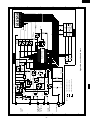
CONTROL PANEL CIRCUIT ............................................................................................................................... 27
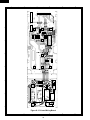
PRINTED WIRING BOARD ................................................................................................................................. 28
PARTS LIST ....................................................................................................................................................... 29
SHARP CORPORATION
R-3S68
R-3S68
SERVICE MANUAL
PRODUCT SPECIFICATIONS
MICROWAVE OVEN
R-3S68
GENERAL IMPORTANT INFORMATION
APPEARANCE VIEW
This Manual has been prepared to provide Sharp Corp. Service
engineers with Operation and Service Information.
It is recommended that service engineers carefully study the
entire text of this manual, so they will be qualified to render
satisfactory customer service.
CAUTION
MICROWAVE RADIATION
DO NOT BECOME EXPOSED TO RADIATION FROM
THE MICROWAVE GENERATOR OR OTHER PARTS
CONDUCTING MICROWAVE ENERGY.
Service engineers should not be exposed to the microwave
energy which may radiate from the magnetron or other
microwave generating devices if it is improperly used or
connected. All input and output microwave connections,
waveguides, flanges and gaskets must be secured. Never
operate the device without a microwave energy absorbing
load attached. Never look into an open waveguide or
antenna while the device is energized.
WARNING
Never operate the oven until the following points are ensured.
(A) The door is tightly closed.
(B) The door brackets and hinges are not defective.
(C) The door packing is not damaged.
(D) The door is not deformed or warped.
(E) There is not any other visible damage with the oven.
Servicing and repair work must be carried out only by trained
service engineers.
OPERATING SEQUENCE
FUNCTION OF IMPORTANT
COMPONENTS
SERVICING AND
TROUBLESHOOTING CHART
TEST PROCEDURE
TOUCH CONTROL PANEL
ASSEMBLY
COMPONENT REPLACEMENT
AND ADJUSTMENT PROCEDURE
MICROWAVE MEASUREMENT
WIRING DIAGRAM
All the parts marked "*" on parts list are used at voltages more
than 250V.
Removal of the outer wrap gives access to potentials above
250V.
All the parts marked "∆" on parts list may cause undue
microwave exposure, by themselves, or when they are damaged, loosened or removed.
SHARP CORPORATION
OSAKA, JAPAN
1
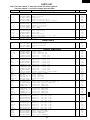
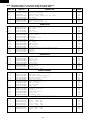
PARTS LIST
R-3S68
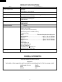
PRODUCT SPECIFICATIONS
ITEM
Power Requirements
Power Consumption
Power Output
Case Dimensions
Cooking Cavity Dimensions
Turntable diameter
Control Complement
Set Weight
DESCRIPTION
220 Volts
50 Hertz
Single phase, 3 wire earthed
1.37kW
850 watts nominal of RF microwave energy (IEC 705)
Operating fequency 2450 MHz
Width 520 mm
Height 305 mm including foot
Depth 389 mm
Width 348 mm
Height 197 mm
Depth 368 mm
325mm
Touch Control System
Clock ( 1:00 - 12:59)
Timer (0 - 99 minutes 90 seconds)
Microwave Power for Variable Cooking
Repetition Rate;
HIGH ............................................... Full power throughout the cooking time
MEDIUM HIGH ..................................................approx. 70% of Full Power
MEDIUM ............................................................. approx. 50% of Full Power
MEDIUM LOW .................................................... approx. 30% of Full Power
LOW .................................................................... approx. 10% of Full Power
TIME pads
AUTO COOK pad
AUTO DEFROST pad
STOP/CLEAR pad
POWER LEVEL /SERVE pad
INSTANT COOK / START pad
Approx. 15 kg
GENERAL INFORMATION
WARNING
THIS APPLIANCE MUST BE EARTHED
IMPOTANT
THE WIRES IN THIS MAINS LEAD ARE COLOURED IN ACCORDANCE WITH THE FOLLOWING CODE:
GREEN-AND-YELLOW
BLUE
BROWN
2
: EARTH
: NEUTRAL
: LIVE
R-3S68
Ventilation openings
Oven lamp
Door hinges
Door safety latches
See through door
Door seals and sealing
surfaces
7. Coupling
8. Door open button
9. Touch control panel
10.Digital readout
11.Wave guide cover
12.Power supply cord
13.Rating label
14.Earth wire
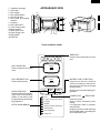
APPEARANCE VIEW
1.
2.
3.
4.
5.
6.
6
1
10
9
3
14
8
4
7
5
12
2 11 4
13
TOUCH CONTROL PANEL
1O
1
MIN.
MIN.
AUTO COOK PAD
Press to select AUTO COOK
menu.
AUTO
AUTO DEFROST PAD
Press to defrost meat.
AUTO
STOP/CLEAR PAD
Press to clear during programming. Press once to stop operation of oven during cooking; press twice to cancel cooking programme.
AUTO COOK MENUS
1O
SEC.
TIME PADS
Press to enter cooking time or clock
time.
COOK
DEFROST
STOP
CLEAR
POWER
LEVEL
SERVE
INSTANT
COOK
START
A1
Rice
A2
Congee / Chicken Sour Soup
A3
Porridge
A4
Noodles
A5
Shark's Fin Soup / Beef Soup
A6
Steamed Fish
A7
Dim Sum Delight
A8
Sticky Rice
3
INSTANT COOK / START PAD
Press once to cook for 1 minute at
100% or increase by 1 minute multiples each time this pad is pressed
during cooking.
Press to start oven after setting programmes.
POWER LEVEL
/ SERVE PAD
Press to set clock.
Press to select microwave power
setting.
If not pressed; 100% is automatically selected.
Press to enter serves after selecting
AUTO COOK menu or pressing the
AUTO DEFROST pad.
R-3S68
OPERATION SEQUENCE
OFF CONDITION
The circuits to the power transformer, fan motor and
turntable motor are cut off when the 1st. latch switch and
2nd. interlock relay control switch are made open. The
oven lamp remains on even if the oven door is opened
after the cooking cycle has been interrupted, because
the relay RY1 stays closed. Shown in the display is the
remaining time.
Closing the door activates all door interlock switches (1st.
latch switch and 2nd. interlock relay control switch).
IMPORTANT
When the oven door is closed, the monitor switch contacts
(COM-NC) must be open.
When the microwave oven is plugged in a wall outlet, rated
voltage is supplied to the point A3+A5 in the control unit.
6.
MONITOR SWITCH CIRCUIT
The monitor switch is mechanically controlled by oven
door, and monitors the operation of the 1st latch switch.
6-1 When the oven door is opened during or after the cycle
of a cooking program, the 1st. latch switch and 2nd.
interlock relay control switch must open their contacts
first.
After that the contacts (COM-NC) of the monitor switch
can be closed.
6-2. When the oven door is closed, the contacts (COM-NC)
of the monitor switch must be opened. After that the
contacts of the 1st. latch switch and 2nd. interlock relay
control switch are closed.
6-3. When the oven door is opened and the contacts of the
1st. latch switch and 2nd. interlock relay remain closed.
The fuse M8A will blow, because the monitor switch is
closed and a short circuit is caused.
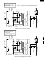
Figure O-1 on page 25
1. The display flashes 88:88 .
2. To set any programmes or set the clock, you must first
touch the STOP/CLEAR pad.
3.
:
appears in the display.
NOTE: When the oven door is opened, the oven lamp
comes on at this time.
MICROWAVE COOKING CONDITION
HIGH COOKING
Enter a desired cooking time with the touching NUMBER
pad and start the oven with touching START pad.
Function sequence
Figure O-2 on page 25
CONNECTED COMPONENTS
Oven lamp, Fan motor, Turntable motor
Power transformer
RELAY
RY1
RY2
MEDIUM HIGH, MEDIUM, MEDIUM LOW, LOW
COOKING
When the microwave oven is preset for variable cooking
power, rated voltage is supplied to the power transformer
intermittently within a 32-second time base through the
relay contact which is coupled with the current-limiting relay.
The following levels of microwave power are given.
1. Rated voltage is supplied to the primary winding of the
power transformer. The voltage is converted to about 3.3
volts A.C. output on the filament winding and high
voltage of approximately 2000 volts A.C. on the secondary
winding.
2. The filament winding voltage (3.3 volts) heats the
magnetron filament and the high voltage (2000 volts) is
sent to the voltage doubling circuit, where it is doubled to
negative voltage of approximately 4000 volts D.C..
3. The 2450 MHz microwave energy produced in the
magnetron generates a wave length of 12.24 cm. This
energy is channelled through the waveguide (transport
channel) into the oven cavity, where the food is placed to
be cooked.
4. When the cooking time is up, a signal tone is heard and
the relays RY1+RY2 go back to their home position. The
circuits to the oven lamp, power transformer, fan motor
and turntable motor are cut off.
5. When the door is opened during a cook cycle, the
switches come to the following condition
SWITCH
CONTACT
CONDITION
DURING
COOKING
1st. latch switch
2nd. interlock relay
control switch
COM-NO
Closed
Open
COM-NO
Closed
Open
Monitor switch
COM-NC
Open
Closed
SETTING;
32 sec. ON
HIGH
24 sec. ON
8 sec. OFF
Approx. 70%
MEDIUM HIGH
18 sec. ON
14 sec. OFF
MEDIUM
Approx. 50%
12 sec. ON
20 sec. OFF
Approx. 30%
MEDIUM LOW
6 sec. ON
LOW
26 sec. OFF
Approx. 10%
NOTE: The ON/OFF time ratio does not exactly correspond
to the percentage of microwave power, because
approx. 2 seconds are needed for heating up the
magnetron filament.
DOOR OPEN
(NO COOKING)
4
R-3S68
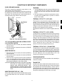
FUNCTION OF IMPORTANT COMPONENTS
DOOR OPEN MECHANISM
FUSE M8A
The door is opened by pushing the open button on the
control panel, refer to the Figure D-1.
When the open button is pushed, the open button pushes up
the switch lever, and then the switch lever pushes up the
latch head. The latch heads are moved upward and released from latch hook. Now the door will open.
1. The fuse M8A blows when the contacts (COM-NO) of the
1st. latch switch and 2nd. interlock relay remain closed
with the oven door open and when the monitor switch
closes.
2. If the wire harness or electrical components are shortcircuited, this fuse M8A blows to prevent an electric
shock or fire hazard.
LATCH HOOK
THERMAL CUT-OUT TC 145˚C (MG)
LATCH
HEADS
SWITCH
LEVER
This thermal cut-out protects the magnetron against overheating. If the temperature goes up higher than 145˚C
because the fan motor is interrupted, the ventilation openings are blocked, the thermal cut-out will open and the line
voltages to the power transformer will be cut off and the
operation of the magnetron will be stopped.
The defective thermal cut-out must be replaced with new
one.
2ND. INTERLOCK
RELAY CONTROL
SWITCH
THERMAL CUT-OUT TC 145˚C (OVEN)
MONITOR
SWITCH
The thermal cut-out located on the top of the oven cavity is
designed to prevent damage to the oven if the foods in the
oven catch fire due to over heating produced by improper
setting of cook time or failure of control unit. Under normal
operation, the oven thermal cut-out remains closed. However, when abnormally high temperatures are reached
within the oven cavity, the oven thermal cut-out will open at
145˚C, causing the oven to shut down. The defective
thermal cut-out must be replace with new one.
1ST. LATCH
SWITCH
Figure D-1. Door Open Mechanism
1ST. LATCH SWITCH AND 2ND. INTERLOCK RELAY CONTROL SWITCH
1. When the oven door is closed, the contacts COM-NO)
must be closed.
2. When the oven door is opened, the contacts .(COM-NO)
must be opened.
THERMAL CUT-OUT 95˚C (FAN MOTOR)
The thermal cut-out protect the fan motor against overheating. If its temperature goes up higher than 95˚C because the
fan motor is locked or the ventilation operating are blocked,
the contacts of the thermal cut-out will open and switch off
the oven. When the oven cools itself down to 75˚C, the
contacts of the thermal cut-out will close again.
MONITOR SWITCH
1. When the oven door is closed, the contacts (COM-NC)
must be opened.
2. When the oven door is opened, the contacts (COM-NC)
must be closed.
3. If the oven door is opened and the contacts (COM-NO)
of the 1st. latch switch and 2nd. interlock relay fail to
open, the fuse M8A blows simultaneously with closing
the contacts (COM-NC) of the monitor switch.
CAUTION: BEFORE REPLACING A BLOWN FUSE M8A
TEST THE 1ST. LATCH SWITCH, MONITOR
SWITCH, 2ND. INTERLOCK RELAY, 2ND.
INTERLOCK RELAY CONTROL SWITCH AND
MONITOR RESISTOR FOR PROPER OPERATION.
TURNTABLE MOTOR
The turntable motor drives the turntable roller assembly to
rotate the turntable.
FAN MOTOR
The fan motor drives a blade which draws external cool air.
This cool air is directed through the air vanes surrounding
the magnetron and cools the magnetron. This air is channelled through the oven cavity to remove steam and vapours given off from the heating foods. It is then exhausted
through the exhausting air vents at the oven cavity
MONITOR RESISTOR R 0.8Ω 20W
The monitor resistor prevents the fuse M8A bursting when
the fuse M8A blows due to the operation of the monitor
switch.
5
R-3S68
SERVICING
WARNING TO SERVICE PERSONNEL
Microwave ovens contain circuitry capable of producing very high voltage and current, contact with any part of the
high voltage circuit will result in electrocution. High voltage capacitor, Power transformer, Magnetron, High voltage
rectifier assembly, High voltage harness.
REMEMBER TO CHECK 3D
REMEMBER TO CHECK 4R
1) Disconnect the supply.
2) Door opened, and wedged open.
3) Discharge high voltage capacitor.
1) Reconnect all leads removed from components during
testing.
2) Replace the outer case (cabinet).
3) Reconnect the supply.
4) Run the oven. Check all functions.
WARNING: AGAINST THE CHARGE OF THE
HIGH-VOLTAGE CAPACITOR
Microwave ovens should not be run empty. To test for
the presence of microwave energy within a cavity, place
a cup of cold water on the oven turntable, close the door
and set the microwave timer for two (2) minutes. Set the
power level to HIGH and push the START button. When
the two minutes has elapsed (timer at zero) carefully
check that the water is now hot. If the water remains cold
carry out 3D checks and re-examine the connections to
the component being tested.
The high-voltage capacitor remains charged about
60 seconds after the oven has been switched off.
Wait for 60 seconds and then short-circuit the connection of the high-voltage capacitor (that is, of the
connecting lead of the high-voltage rectifier) against
the chassis with the use of an insulated screwdriver.
Sharp recommend that wherever possible fault-finding
is carried out with the supply disconnected. It may in,
some cases, be necessary to connect the supply after
the outer case has been removed, in this event carry out
3D checks and then disconnect the leads to the primary
of the power transformer. Ensure that these leads remain isolated from other components and the oven
chassis. (Use insulation tape if necessary.) When the
testing is completed carry out 3D checks and reconnect
the leads to the primary of the power transformer.
When all service work is completed, and the oven is fully assembled, the microwave power output should be checked
and microwave leakage test carried out
TROUBLESHOOTING GUIDE
When troubleshooting the microwave oven, it is helpful to
follow the Sequence of Operation in performing the
checks. Many of the possible causes of trouble will require
that a specific test be performed. These tests are given a
procedure letter which will be found in the "Test
Procedure"section.
IMPORTANT: If the oven becomes inoperative because
of a blown fuse M8A in the 1st. latch switch
- 2nd. interlock relay - monitor switch monitor resistor circuit, check the 1st. latch
switch, 2nd. interlock relay, 2nd. interlock
relay control switch, monitor switch and
monitor resistor before replacing the fuse
M8A.
6
R-3S68
CK = Check / RE = Replace
Home fuse blows when power
supply cord is plugged into wall
outlet.
FUSE M8A blows when power
supply cord is plugged into wall
outlet.
OFF
CONDITION
Display does not show anything
when power supply cord is plugged
into wall outlet.
Display does not operate properly when STOP/CLEAR pad is
touched.
Oven lamp does not light at door
opened. (Display appears.)
Oven does not start when the
START pad is touched. (Display
appears)
Oven lamp does not light (Display
appears.)
Fan motor does not operate. (Display appears.)
Turntable motor assembly does
not operate. (Display appears.)
Oven or any electrical parts does
not stop when cooking time is 0 or
STOP/CLEAR pad is touched.
ON
CONDITION
Oven seems to be operating but
little or no heat is produced in
oven load. (Microwave power level
is set at HIGH)
Oven does not seems to be operating properly when MEDIUM
HIGH, MEDIUM, MEDIUM LOW
or LOW is set. (Oven operates
properly at HIGH and when the
STOP/CLEAR pad is touched the
oven stops.)
Oven goes into cook cycle but
shuts down before end of cooking
cycle.
7
BLOCKED VENTILATION
BLOCKED COOLING FAN
MISADJUSTMENT SWITCH
HOME FUSE OR BREAKER
WALL OUTLET
OVEN LAMP OR SOCKET
SHORTED WIRE HARNESS
OPENED WIRE HARNESS
RECKCKRE CK CKCKCK CK
POWER SUPPLY CORD
RELAY (RY-1, RY-2)
FOIL PATERN ON P.W.B.
TACT SWITCH
TOUCH CONTROL PANEL
TURNTABLE MOTOR
FUSE M8A
FAN MOTOR
MONITOR RESISTOR
THERMAL CUT-OUT 95˚C
THERMAL CUT-OUT 145˚C
PROBLEM
POWER TRANSFORMER
H.V. RECTIFIER ASSEMBLY
CONDITION
MAGNETRON
POSSIBLE CAUSE
AND
DEFECTIVE PARTS
1ST. LATCH SWITCH
2ND. INTERLOCK RELAY
CONTROL SWITCH
MONITOR SWITCH
A B C D E E E G F F H H I K L M N
HIGH VOLTAGE CAPACITOR
TEST PROCEDURE
R-3S68
TEST PROCEDURES
PROCEDURE
LETTER
A
COMPONENT TEST
MAGNETRON TEST
NEVER TOUCH ANY PART IN THE CIRCUIT WITH YOUR HAND OR AN INSULATED TOOL
WHILE THE OVEN IS IN OPERATION.
CARRY OUT 3D CHECK.
Isolate the magnetron from high voltage circuit by removing all leads connected to filament terminal.
To test for an open circuit filament use an ohmmeter to make a continuity test between the magnetron
filament terminals, the meter should show a reading of less than 1 ohm.
To test for short filament to anode condition, connect ohmmeter between one of the filament terminals
and the case of the magnetron (ground). This test should be indicated an infinite resistance. If a low or
zero resistance reading is obtained then the magnetron should be replaced.
MICROWAVE OUTPUT POWER (IEC 705)
The following test procedure should be carried out with the microwave oven in a fully assembled
condition (outer case fitted). Microwave output power from the magnetron can be measured by way of
IEC 705, i.e. it can be measured by using water load how much it can be absorbed by the water load.
To measure the microwave output power in the microwave oven, the relation of calorie and watt is used.
When P(W) heating works for t(second), approximately P x t/4.187 calorie is generated. On the other
hand, if the temperature of the water with V(ml) rises ∆T (°C) during this microwave heating period, the
calorie of the water is V x ∆T.
The formula is as follows;
P x t / 4.187 = V x ∆ T
P (W) = 4.187 x V x ∆T / t
Our condition for water load is as follows:
Room temperature..............around 20°C
Power supply Voltage.........Rated voltage
Water load.........1000 g Initial temperature...........10±2°C Heating time.........49 sec.
P = 85 x ∆T
Measuring condition:
1. Container
The water container must be a cylindrical borosilicate glass vessel having a maximum material
thickness of 3 mm and an outside diameter of approximately 190 mm.
2. Temperature of the oven and vessel
The oven and the empty vessel are at ambient temperature prior to the start the test.
3. Temperature of the water
The initial temperature of the water is (10±2)°C.
4. Select the initial and final water temperature so that the maximum difference between the final water
temperature and the ambient temperature is 5˚C.
5. Select stirring devices and measuring instruments in order to minimize addition or removal of heat.
6. The graduation of the thermometer must be scaled by 0.1°C at minimum and accurate thermometer.
7. The water load must be (1000±5) g.
8. “t” is measured while the microwave generator is operating at full power. Magnetron filament heatup time is not included.
NOTE: The operation time of the microwave oven is “t + 2” sec. 2 sec. is magnetron filament heat-up time.
Measuring method:
1. Measure the initial temperature of the water before the water is added to the vessel.
(Example: The initial temperature T1 = 11°C)
2. Add the 1 litre water to the vessel.
3. Place the load on the centre of the shelf.
4. Operate the microwave oven at HIGH for the temperature of the water rises by a value ∆ T of
(10 ± 2)˚C.
5. Stir the water to equalize temperature throughout the vessel.
8
R-3S68
TEST PROCEDURES
PROCEDURE
LETTER
COMPONENT TEST
6. Measure the final water temperature. (Example: The final temperature T2 = 21°C)
7. Calculate the microwave power output P in watts from above formula.
Initial temperature .................................................................................................. T1 = 11°C
Temperature after (49 + 2) = 51 sec. ..................................................................... T2 = 21°C
Temperature difference Cold-Warm.................................................................... ∆T1 = 10°C
Measured output power
The equation is “P = 85 x ∆T” ...................................................... P = 85 x 10°C = 850 Watts
JUDGMENT: The measured output power should be at least ± 15 % of the rated output power.
CAUTION: 1°C CORRESPONDS TO 85 WATTS REPEAT MEASUREMENT IF THE POWER IS
INSUFFICIENT.
1000g
1000g
1000g
T1˚C
T2˚C
Heat up for 51 sec.
B
POWER TRANSFORMER TEST
WARNING: High voltages and large currents are present at the secondary winding and filament
winding of the power transformer. It is very dangerous to work near this part when
the oven is on. NEVER make any voltage measurements of the high-voltage
circuits, including the magnetron filament.
CARRY OUT 3D CHECKS.
Disconnect the leads to the primary winding of the power transformer. Disconnect the filament and
secondary winding connections from the rest of the HV circuitry. Using an ohmmeter, set on a low range,
it is possible to check the continuity of all three windings. The following readings should be obtained:
a. Primary winding ....................approx. 1.4 Ω
b. Secondary winding ............... approx. 98 Ω
c. Filament winding ................... less than 1Ω
If the reading obtained are not stated as above, then the power transformer is probably faulty and should
be replaced.
CARRY OUT 4R CHECKS.
C
HIGH VOLTAGE RECTIFIER ASSEMBLY TEST
HIGH VOLTAGE RECTIFIER TEST
CARRY OUT 3D CHECKS.
Isolate the high voltage rectifier assembly from the HV circuit. The high voltage rectifier can be tested
using an ohmmeter set to its highest range. Connect the ohmmeter across the terminal B+C of the high
voltage rectifier and note the reading obtained. Reverse the meter leads and note this second reading.
The normal resistance is infinite in one direction and more than 100 kΩ in the other direction.
9
R-3S68
TEST PROCEDURES (CONT'D)
PROCEDURE
LETTER
COMPONENT TEST
C
B
CARRY OUT 4R CHECKS.
HIGH VOLTAGE RECTIFIER
NOTE: FOR MEASUREMENT OF THE RESISTANCE OF THE RECTIFIER, THE BATTERIES OF THE
MEASURING INSTRUMENT MUST HAVE A VOLTAGE AT LEAST 6 VOLTS, BECAUSE
OTHERWISE AN INFINITE RESISTANCE MIGHT BE SHOWN IN BOTH DIRECTIONS.
D
HIGH VOLTAGE CAPACITOR TEST
CARRY OUT 3D CHECKS.
A. Isolate the high voltage capacitor from the circuit.
B. Continuity check must be carried out with measuring instrument which is set to the highest resistance
range.
C. A normal capacitor shows continuity for a short time (kick) and then a resistance of about 10MΩ after it has
been charged.
D. A short-circuited capacitor shows continuity all the time.
E. An open capacitor constantly shows a resistance about 10 MΩ because of its internal 10MΩ resistance.
F. When the internal wire is opened in the high voltage capacitor shows an infinite resistance.
G. The resistance across all the terminals and the chassis must be infinite when the capacitor is normal.
If incorrect reading are obtained, the high voltage capacitor must be replaced.
CARRY OUT 4R CHECKS.
E
SWITCH TEST
CARRY OUT 3D CHECKS.
Isolate the switch to be tested and using an ohmmeter check between the terminals as described in the
following table.
COM; Common terminal,
Table: Terminal Connection of Switch
Plunger Operation
Released
Depressed
COM to NO
O.C.
S.C.
COM to NC
S.C.
O.C.
NO;
NC;
S.C.;
O.C.;
Normally open terminal
Normally close terminal
Short,
Open circuit
If incorrect readings are obtained, make the necessary switch adjustment or replace the switch.
CARRY OUT 4R CHECKS.
F
THERMAL CUT-OUT TEST
CARRY OUT 3D CHECKS.
Disconnect the leads from the terminals of the thermal cut-out. Then using an ohmmeter, make a
continuity test across the two terminals as described in the table below.
CARRY OUT 4R CHECKS
.Table: Thermal cut-out Test
Parts Name
Temperature of "ON" condition
(closed circuit) (˚C)
Temperature of "OFF" condition
(open circuit) (˚C)
Thermal cut-out 145˚C
Thermal cut-out 95˚C
This is not resetable type
Below 75˚C
Above 145˚C
Above 95˚C
Indication ofohmmeter
(When room temperature
is approx. 20˚C)
Closed circuit.
Closed circuit.
If incorrect readings are obtained, replace the thermal cut-out.
An open circuit thermal cut-out 145˚C (MG) indicates that the magnetron has overheated, this may be
due to resistricted ventilation, cooling fan failure or a fault condition within the magnetron or HV circuit.
An open circuit thermal cut-out 145˚C (OVEN) indicates that the foods in the oven may catch fire, this
may be due to over heating produced by improper setting of the cooking time or failure of the control
panel.
An open circuit thermal cut-out 95˚C (FAN) indicates that the fan motor winding has overheated, this
may be due to blocked ventilation or locked cooling fan.
10
R-3S68
TEST PROCEDURES (CONT'D)
PROCEDURE
LETTER
G
COMPONENT TEST
MONITOR RESISTOR TEST
CARRY OUT 3D CHECKS.
Disconnect the leads from the monitor resist. Using an ohmmeter and set on a low range. Check between
the terminals of the monitor resistor.
The resistance of monitor resistor is approx. 0.8 ohms.
If incorrect readings are obtained, replace the monitor resistor.
CARRY OUT 4R CHECKS.
H
MOTOR WINDING TEST
CARRY OUT 3D CHECKS.
Disconnect the leads from the motor.
Using an ohmmeter, check the resistance between the two terminals as described in the table below.
Table: Resistance of Motor
Motors
Resistance
Fan motor
Approximately 370 Ω
Turntable motor
Approximately 16.08 kΩ
If incorrect readings are obtained, replace the motor.
I
CARRY OUT 4R CHECKS
BLOWN FUSE F M8A
CARRY OUT 3D CHECKS.
1. If the fuse M8A is blown, there could be shorts or ground in electrical parts or wire harness.
Check them and replace the defective parts or repair the wire harness.
2. If the fuse M8A is blown when the door is opened, check the 1st. latch switch, 2nd. interlock relay,
2nd. interlock relaycontrol switch, monitor switch and monitor resistor.
If the fuse M8A is blown by incorrect door switching replace the defective switch(s) and the fuse M8A.
CARRY OUT 4R CHECKS.
CAUTION: ONLY REPLACE FUSE M8A WITH THE CORRECT VALUE REPLACEMENT.
J
TOUCH CONTROL PANEL ASSEMBLY TEST
The touch control panel consists of circuits including semiconductors such as LSI, ICs, etc. Therefore,
unlike conventional microwave ovens, proper maintenance cannot be performed with only a voltmeter
and ohmmeter.
In this service manual, the touch control panel assembly is in one unit, and troubleshooting by unit
replacement is described according to the symptoms indicated.
1. Tact Switch.
The following symptoms indicate a defective tact switch. Replace the tact switch.
a) When touching the tact switches, a certain tact switch produces no signal at all.
b) When touching the tact switches, sometimes a tact switch produces no signal.
2. Control Panel
The following symptoms may indicate a defective control unit. Before replacing the control unit,
perform the tact switch test (Procedure K) to determine if control unit is faulty.
2-1 In connection with tact switches.
a) When touching the tact switches, a certain group of tact switches do not produce a signal.
b) When touching the tact switches, no tact switches produce a signal.
11
R-3S68
TEST PROCEDURES (CONT'D)
PROCEDURE
LETTER
COMPONENT TEST
2-2 In connection with indicators
a) At a certain digit, all or some segments do not light up.
b) At a certain digit, brightness is low.
c) Only one indicator does not light.
d) The corresponding segments of all digits do not light up or they continue to light up.
e) Wrong figure appears.
f) A certain group of indicators do not light up.
g) The figure of all digits flicker.
2-3 Other possible problems caused by defective control unit.
a) Buzzer does not sound or continues to sound.
b) Cooking is not possible.
K
TACT SWITCH TEST
If the display fails to clear when the STOP/CLEAR tact switch is depressed, first verify that the door
sensing switch (stop switch) operates properly; that is the contacts are closed when the door is closed
and open when the door is open. If the door sensing switch (stop switch) is good, make sure the door
sensing switch is closed (either close the door or short the door sensing switch connecter). Use the tact
switch matrix indicated on the control panel schematic and place a jumper wire between the pins that
correspond to the STOP/CLEAR tact switch making momentary contact. If the control unit responds by
clearing with a beep, the tact switch is faulty and must be replaced. If the control unit does not respond,
it is a faulty and must be replaced. If a specific pad does not respond, the above method may be used
(after clearing the control unit) to determine if the control unit or tact switch is at fault.
SW1
10
MIN.
SW2
1
MIN.
SW5
SW4
AUTO COOK
SW3
SW6
AUTO DEFROST
10
SEC.
STOP
CLEAR
SW7 POWER SW8 INSTANT
LEVEL
SERVE
L
COOK
START
RELAY TEST
CARRY OUT 3D CHECKS.
Remove the outer case and check voltage between Pin Nos. 3 and 5 of the 3 pin connector (A) on the
control unit with an A.C. voltmeter.
The meter should indicate 220 volts, if not check oven circuit.
RY1 and RY2 Relay Test
These relays are operated by D.C. voltage.
Check voltage at the relay coil with a D.C. voltmeter during the microwave cooking or convection cooking
operation.
DC. voltage indicated .................... Defective relay.
DC. voltage not indicated . ............ Check diode which is connected to the relay coil. If diode is good,
control unit is defective.
RELAY SYMBOL
OPERATIONAL VOLTAGE
CONNECTED COMPONENTS
RY1
APPROX. 19.0V D.C.
Oven lamp / Turntable motor / Cooling fan motor
RY2
APPROX. 18.0V D.C.
Power transformer
CARRY OUT 4R CHECKS.
12
R-3S68
TEST PROCEDURES (CONT'D)
PROCEDURE
LETTER
M
COMPONENT TEST
PROCEDURES TO BE TAKEN WHEN THE FOIL PATTERN ON THE PRINTED WIRING BOARD
(PWB) IS OPEN
To protect the electronic circuits, this model is provided with a fine foil pattern added to the primary on
the PWB, this foil pattern acts as a fuse. If the foil pattern is open, follow the troubleshooting guide given
below for repair.
Problem: POWER ON, indicator does not light up.
CARRY OUT 3D CHECKS.
STEPS
1
OCCURANCE
CAUSE OR CORRECTION
3
The rated voltage is not applied to POWER
terminal of CPU connector (CN-A).
The rated voltage is applied to primary side
of low voltage transformer.
Only pattern at "a" is broken.
4
Pattern at "a" and "b" are broken.
2
Check supply voltage and oven main unit.
Low voltage transformer or secondary circuit defective.
Check and repair.
*Insert jumper wire J1 and solder.
(CARRY OUT 3D CHECKS BEFORE REPAIR)
*Insert the coil RCILF2003YAZZ between "c" and "d".
(CARRY OUT 3D CHECKS BEFORE REPAIR)
d
LEAD
WIRE
CARRY OUT 4R CHECKS.
13
(J1)
c
CN - A
b
a
VRS1
LEAD WIRE
GREEN
RY1
D22
RY2
2
NOTE: At the time of these repairs, make a visual
inspection of the varistor for burning
damage and examine the transformer
with tester for the presence of layer shortcircuit (check primary coil resistance). If
any abnormal condition is detected,
replace the defective parts.
5
1
3
POWER
OL TTM
R-3S68
TOUCH CONTROL PANEL ASSEMBLY
OUTLINE OF TOUCH CONTROL PANEL
5) ACL Circuit
A circuit to generate a signals which resets the LSI to the
initial state when power is supplied.
Control Unit
Control unit consists of tact switches, LSI, power source
circuit, synchronizing signal circuit, ACL circuit, buzzer
circuit and indicator circuit.
6) Buzzer Circuit
The buzzer is responsive to signals from the LSI to emit
noticing sounds (key touch sound and completion sound).
1) Tact Switches
The tact switches are composed of a matrix, signals
generated in the LSI are sent to the tact switches through
R61-R63. When a tact switches is touched, a signal is
completed through the tact switches and passed back to
the LSI through R81-R83 to perform the function that
was requested.
7) Door Sensing Switch
A switch to “tell” the LSI if the door is open or closed.
8) Relay Circuit
To drive the magnetron, fan motor, turntable motor and
light the oven lamp.
2) LSI
This LSI controls the key strobe signal, relay driving
signal for oven function and indicator signal.
9) Indicator Circuit
Indicator element is a Light-emitting diode.
Basically, a Light-emitting diode is triode having a cathode
and an anode.
The Light-emitting diode has 4-digits, 9-segments are
used for displaying figures.
3) Power Source Circuit
This circuit generates voltages necessary in the control
unit.
Symbol
VC
Voltage
-5V
Application
LSI(IC1)
4) Synchronizing Signal Circuit
The power source synchronizing signal is available in
order to compose a basic standard time in the clock
circuit. It accompanies a very small error because it
works on commercial frequency.
14
R-3S68
DESCRIPTION OF LSI
LSI(IZA677DR)
The I/O signal of the LSI(IZA677DR) is detailed in the following table.
Pin No.
Signal
I/O
Description
1
XOUT
OUT
2
XIN
IN
Internal clock oscillation frequency input setting.
The internal clock frequency is set by inserting the ceramic filter oscillation circuit with
respect to XIN terminal.
3
RESET
IN
Auto clear terminal.
Signal is input to reset the LSI to the initial state when power is supplied. Temporarily
set to “L” level the moment power is supplied, at this time the LSI is set. Thereafter set
at “H” level.
4
R70
OUT
Segment data signal.
Refer to the touch control panel circuit for the relationship between signals and
indicators. Normally, one pulse is output in every synchronized signal period, and
input to the anode of the light -emitting diode.
5
PULSE
OUT
Signal to sound buzzer.
Internal clock oscillation frequency control output.
Output to control oscillation input of XOUT.
A: key touch sound(0.12 sec.).
B: Completion sound(2.4 sec.).
6
R72
OUT
Digit selection signal.
Refer to the touch control panel circuit about the relation between signals and digits.
Normally, one pulse is output in every synchronized signal period, and input to the light
-emitting diode.
7-9
R40-R42
OUT
Digit selection signal.
Refer to the touch control panel circuit about the relation between signals and digits.
Normally, one pulse is output in every synchronized signal period, and input to the light
-emitting diode.
10
AIN3
IN
11
R50
OUT
Segment data signal.
Signal similar to R70.
R51-R52
OUT
Segment data signal.
Refer to the touch control panel circuit for the relationship between signals and
indicators. Normally, one pulse is output in every synchronized signal period, and
input to the anode of the light -emitting diode.
14
VSS
IN
15
R53
OUT
Segment data signal.
Signal similar to R70.
16
R60
OUT
Segment data signal.
Signal similar to R70.
17
R61
OUT
Segment data signal.
Signal similar to R70.
12-13
Terminal to change cooking constant.
Connected to VC.
Switch strobe signal.
Signal applied to tact switch section. A pulse signal is input to R81, R82 and R83
terminal while one of diode D56 line switches on switch matrix is touched.
18
R62
OUT
Segment data signal.
Signal similar to R70.
Switch strobe signal.
Signal applied to tact switch section. A pulse signal is input to R81, R82 and R83
terminal while one of diode D57 line switches on switch matrix is touched.
15
R-3S68
Pin No.
19
Signal
R63
I/O
OUT
Description
Segment data signal.
Signal similar to R70.
Switch strobe signal.
Signal applied to tact switch section. A pulse signal is input to R81, R82 and R83
terminal while one of diode D58 line switches on switch matrix is touched.
20
INT2
IN
Signal synchronized with commercial source frequency(50Hz).
This is basic timing for time processing of LSI.
21
R81
IN
Signal coming from touch tact switch.
When either one of resistor R80 line switches on switch matrix is touched, a
corresponding signal out of R61-R63 will be input into R81. When no key is touched,
the signal is held at "L" level.
22
R82
IN
Signal coming from touch tact switch.
When either one of resistor R81 line switches on switch matrix is touched, a
corresponding signal out of R61-R63 will be input into R82.
23
R83
IN
Signal coming from touch tact switch.
When either one of resistor R82 line switches on switch matrix is touched, a
corresponding signal out of R61-R63 will be input into R83.
24
R90
OUT
Terminal not used.
25
R91
OUT
Oven lamp, turntable motor and cooling fan motor driving signal. (Square
Waveform : 50Hz)
To turn on and off the control relay. The pulse signal (50Hz) is delivered to the control
relay driving circuit and cook relay control circuit.
26
R92
OUT
Magnetron high-voltage circuit driving signal.
To turn on and off the cook relay. In 100% power operation, the signals holds “L” level
during microwave cooking and “H” level while not cooking. In other cooking modes
(10%, 30%, 50%, 70%) the signal turns to “H” level and “L” level in repetition according
to the power level.
27
KE0
IN
Input signal which communicates the door open/close information to LSI.
Door closed; “H” level signal.
Door opened; “L” level signal.
28
VDD
IN
Connected to GND.
16
R-3S68
SERVICING
1. Precautions for Handling Electronic Components
This unit uses CMOS LSI in the integral part of the
circuits. When handling these parts, the following precautions should be strictly followed. CMOS LSI have
extremely high impedance at its input and output terminals. For this reason, it is easily influenced by the
surrounding high voltage power source, static electricity
charge in clothes, etc. and sometimes it is not fully
protected by the built-in protection circuit.
In order to protect CMOS LSI.
1) When storing and transporting, thoroughly wrap them in
aluminium foil. Also wrap all PW boards containing them
in aluminium foil.
2) When soldering, ground the technician as shown in the
figure and use grounded soldering iron and work table.
B. On some models, the power supply cord between the
touch control panel and the oven proper is long enough
that they may be separated from each other. For those
models, therefore, it is possible to check and repair the
controls of the touch control panel while keeping it apart
from the oven proper; in this case you must short both
ends of the door sensing switch (on PWB) of the touch
control panel with a jumper, which brings about an
operational state that is equivalent to the oven door
being closed. As for the sensor-related controls of the
touch control panel, checking them is possible if dummy
resistor(s) with resistance equal to that of the controls
are used.
(2) Servicing the touch control panel with power supply
from an external power source:
Disconnect the touch control panel completely from the
oven proper,and short both ends of the door sensing
switch (on PWB) of the touch control panel,which brings
about an operational state that is equivalent to the oven
door being closed. Connect an external power source to
the power input terminal of the touch control panel, then
it is possible to check and repair the controls of the touch
control panel it is also possible to check the sensorrelated controls of the touch control panel by using the
dummy resistor(s).
approx. 1M ohm
2. Shapes of Electronic Components
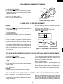
1
2
3
IC
LM7905CT
E
CB
Transistor
KRA101M
KRA222M
KRA223M
KRC243M
4. Servicing Tools
Tools required to service the touch control panel assembly.
1) Soldering iron: 30W
(It is recommended to use a soldering iron with a
grounding terminal.)
2) Oscilloscope: Single beam, frequency range: DC-10MHz
type or more advanced model.
3) Others: Hand tools
3. Servicing of Touch Control Panel
We describe the procedures to permit servicing of the
touch control panel of the microwave oven and the
precautions you must take when doing so. To perform
the servicing, power to the touch control panel is available either from the power line of the oven itself or from
an external power source.
(1) Servicing the touch control panel with power supply
of the oven:
CAUTION:
THE HIGH VOLTAGE TRANSFORMER OF THE MICROWAVE OVEN IS STILL LIVE DURING SERVICING PRESENTS A HAZARD.
Therefore, when checking the performance of the touch
control panel, put the outer cabinet on the oven to avoid
touching the high voltage transformer, or unplug the
primary terminal (connector) of the high voltage transformer to turn it off; the end of such connector must be
insulated with an insulating tape. After servicing, be sure
to replace the leads to their original locations.
A. On some models, the power supply cord between the
touch control panel and the oven itself is so short that the
two can’t be separated. For those models, check and
repair all the controls (sensor-related ones included) of
the touch control panel while keeping it connected to the
oven.
5. Other Precautions
1) Before turning on the power source of the control unit,
remove the aluminium foil applied for preventing static
electricity.
2) After aluminium foil is removed, be careful that abnormal
voltage due to static electricity etc. is not applied to the
input or output terminals.
3) Attach connectors, electrolytic capacitors, etc. to PWB,
making sure that all connections are tight.
4) Be sure to use specified components where high precision is required.
17
R-3S68
COMPONENT REPLACEMENT AND ADJUSTMENT PROCEDURE
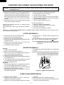
WARNING: Avoid possible exposure to microwave energy. Please follow the instructions below before
operating the oven.
1. Disconnect oven from power supply.
2. Make sure that a definite” click” can be heard when the
microwave oven door is unlatched. (Hold the door in a
closed position with one hand, then push the door open
button with the other, this causes the latch leads to rise,
it is then possible to hear a “click’ as the door switches
operate.)
3. Visually check the door and cavity face plate for damage
(dents, cracks, signs of arcing etc.).
1.
2.
3.
4.
5.
6.
Door does not close firmly.
Door hinge, support or latch hook is damaged.
The door gasket or seal or damaged.
The door is bent or warped.
There are defective parts in the door interlock system.
There are defective parts in the microwave generating
and transmission assembly.
7. There is visible damage to the oven.
Do not operate the oven:
1. Without the RF gasket (Magnetron).
2. If the wave guide or oven cavity are not intact.
3. If the door is not closed.
4. If the outer case (cabinet) is not fitted.
Carry out any remedial work that is necessary before
operating the oven.
Do not operate the oven if any of the following conditions
exist;
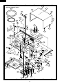
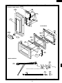
Please refer to ‘OVEN PARTS, CABINET PARTS, CONTROL PANEL PARTS, DOOR PARTS’, when carrying out any of
the following removal procedures:
OUTER CASE REMOVAL
6. Discharge the H.V. capacitor before carrying out any
further work.
7. Do not operate the oven with the outer case removed.
N.B.; Step 1, 2 and 6 form the basis of the 3D checks.
To remove the outer case proceed as follows.
1. Disconnect oven from power supply.
2. Open the oven door and wedge it open.
3. Remove the six (6) screws from rear and along the right
side edge of case.
4. Slide the entire case back about 3cm to free it from
retaining clips on the cavity face plate.
5. Lift the entire case from the unit.
CAUTION: DISCHARGE HIGH VOLTAGE CAPACITOR
BEFORE TOUCHING ANY OVEN COMPONENT
OR WIRING.
MAGNETRON REMOVAL
Removal
1. CARRY OUT 3D CHECKS.
2. Disconnect wire leads from magnetron.
3. Remove the two (2) screws holding chassis support to
oven cavity front plate and magnetron.
4. Remove the chassis support from oven.
5. Carefully remove the two (2) screws holding magnetron
to waveguide flange.
6. Lift up magnetron with care so that magnetron antenna
is not hit by any metal object around antenna.
7. Now, the magnetron is free.
Re-install
1. Re-install the magnetron to waveguide flange with the
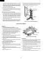
two (2) screws diagonally as shown in Figure C-1.
2. Re-install the chassis support to oven cavity front plate
and magnetron with the two (2) screws.
3. Reconnect the wire leads to the magnetron. Refer to
"PICTORIAL DIAGRAM".
4. Re-install outer case and check that the oven is operating
properly.
CAUTION: WHEN REPLACING MAGNETRON, BE SURE
THE R.F. GASKET IS IN PLACE AND MOUNTING SCREWS ARE TIGHTENED SECURELY
SCREWS
MAGNETRON
WAVEGUIDE
FLANGE
Figure C-1. Magnetron replacement
POWER TRANSFORMER REMOVAL
1. CARRY OUT 3D CHECKS.
2. Disconnect wire leads from power transformer,
magnetron and capacitor terminals.
3. Remove four (4) screws holding transformer to bottom
plate right.
4. Remove transformer from bottom plate right.
5. Remove the one (1) terminal insulator from filament lead
(longer one) of power transformer.
18
R-3S68
Re-install
1. Insert tube into filament lead (longer one) of power
transformer.
2. Install the terminal insulator to receptacle of filament
lead (longer one) of power transformer.
3. Rest transformer on the bottom plate right with its primary
terminals toward the oven face plate.
4. Secure transformer with four screws to bottom plate right.
5. Re-connect wire leads (primary and high voltage) to
power transformer and filament leads of transformer to
magnetron and high voltage capacitor. Refer to
"PICTORIAL DIAGRAM".
6. Re-install outer case and check that oven is operating
properly.
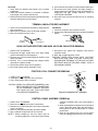
TERMINAL INSULATOR REPLACEMENT
1. Open covers of the terminal insulator by using small flat
type screw driver.
2. Remove the receptacle from the terminal insulator.
3. Now, the terminal insulator is free.
Installation
1. Insert the receptacle into terminal insulator.
2. Close covers of the terminal insulator, as shown illustrated
below.
COVERS
Terminal
insulator
Flat type
screw driver
RECEPTACLE
HIGH VOLTAGE RECTIFIER AND HIGH VOLTAGE CAPACITOR REMOVAL
1. CARRY OUT 3D CHECKS.
2. Disconnect the high voltage wire of the high voltage
rectifier assembly from the magnetron.
3. Remove one (1) screw holding capacitor holder to oven
cavity rear plate.
4. Remove one (1) screw holding high voltage rectifier
assembly to capacitor holder.
5. Disconnect rectifier terminal from capacitor.
6. Now, high voltage rectifier assembly is free.
7. Disconnect wire leads from capacitor and remove
capacitor holder.
8. Now, high voltage capacitor is free.
CAUTION: WHEN REPLACING HIGH VOLTAGE
RECTIFIER AND HIGH VOLTAGE CAPACITOR,
GROUND SIDE TERMINAL OF THE HIGH VOLTAGE
RECTIFIER MUST BE SECURED FIRMLY WITH A
GROUNDING SCREW.
POSITIVE LOCK® CONNECTOR REMOVAL
Terminal
Positive lock®
connector
1. CARRY OUT 3D CHECKS.
2. Pushing the lever of positive lock® connector.
3. Pull out the positive lock® connector.
1
Push
Lever
CAUTION: WHEN YOU (SERVICE ENGINEERS) CONNECT THE POSITIVE LOCK® CONNECTORS
TO THE TERMINALS, CONNECT THE POSITIVE LOCK® SO THAT THE LEVER FACE
YOU (SERVICE ENGINEERS).
2
Pull down
Figure C-2. Positive lock® connector
CONTROL PANEL ASSEMBLY REMOVAL
surfaces completely with a soft cloth soaked in
alcohol.
2. When attaching the key sheet to the control panel
frame, adjust the upper edge and right edge of
the key sheet to the correct position of control
panel frame.
3. Stick the key sheet firmly to the control panel
frame by rubbing with soft cloth not to scratch.
1. CARRY OUT 3D CHECKS.
2. Disconnect wire leads from panel components.
3. Release one (1) nail holding the control panel assembly
to the oven flange.
4. Remove control panel assembly and slide upward.
5 . Now, individual components can be removed.
NOTE: 1. Before attaching a new key sheet, wipe off
remaining adhesive on the control panel frame
19
R-3S68
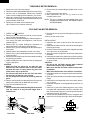
TURNTABLE MOTOR REMOVAL
6. Remove two (2) screws holding turntable motor to oven
cavity.
7. Now the turntable motor is free.
8. After replacement use the one (1) screw to fit the
turntable motor cover.
NOTE: The one (1) screw to fit the turntable motor cover
should be XOTSD40P12000, XOTSD40P10000 or
XOTSD40P08000.
1. Disconnect oven from power supply.
2. Remove turntable and turntable support from oven cavity.
3. Lay the oven on it's backside. Remove the turntable
motor cover by snipping off the material in four corner.
4. Where the corners have been snipped off bend corner
areas flat. No sharp edge must be evident after removal
of the turntable motor cover.
5. Disconnect wire leads from turntable motor.
(See "Positive lock connector removal")
COOLING FAN MOTOR REMOVAL
9. Remove the two (2) screws holding the fan motor to the
fan duct.
10.Now, the fan motor is free.
1. CARRY OUT 3D CHECKS.
2. Disconnect the wire leads from the fan motor, thermal
cut-out (FAN) and magnetron.
3. Remove two (2) screws holding the chassis support to
oven cavity front plate and magnetron. And remove
chassis support.
4. Remove two (2) screws holding the magnetron to
waveguide flange. And remove the magnetron.
5. Remove one (1) screw holding the fan duct assembly to
oven cavity.
6. Release the fan duct assembly from the oven cavity.
7. Remove one (1) screw holding the thermal cut-out angle
to the fan motor.
8. Remove the fan blade from the fan motor shaft according
the following procedure.
1) Hold the edge of the rotor of the fan motor by using a pair
of grove joint pliers.
CAUTION:
* Make sure that any pieces do not enter the gap
between the rotor and the stator of the fan motor
because the rotor is easily shaven by pliers and
metal pieces may be produced.
* Do not touch the pliers to the coil of the fan motor
because the coil may be cut or injured.
* Do not disfigure the bracket by touching with the
pliers.
2) Remove the fan blade from the shaft of the fan motor by
pulling and rotating the fan blade with your hand.
3) Now, the fan blade will be free.
CAUTION:
* Do not use this removed fan blade again because the
hole (for shaft) of it may become bigger than a
standard one.
INSTALLATION
1. Install the fan motor to the fan duct with the two (2)
screws.
2. Install the fan blade to the fan motor shaft according the
following procedure.
1) Hold the centre of the bracket which supports the shaft
of the fan motor on the flat table.
2) Apply the screw lock tight into the hole (for shaft) of the
fan blade.
3) Install the fan blade to the shaft of fan motor by pushing
the fan blade with a small, light weight, ball peen hammer
or rubber mallet.
CAUTION:
* Do not hit the fan blade strongly when installed
because the bracket may be disfigured.
* Make sure that the fan blade rotates smooth after
installation.
* Make sure that the axis of the shaft is not slanted.
3. Install the thermal cut-out angle to the fan motor with one
(1) screw.
4. Catch two holes of fan duct on two tabs of the waveguide
flange.
5. Install the fan duct assembly to the oven cavity with the
one (1) screw.
6. Install the magnetron to waveguide flange with two (2)
screws.
7. Install one (1) tab of the chassis support to oven cavity
front plate and install another tab of it to rear plate. And
then screw chassis support to oven cavity front plate and
magnetron with two (2) screws.
8. Connect the wire leads to the fan motor, magnetron and
thermal cut-out (FAN), referring to the pictorial diagram.
Coil
Groove joint pliers
Shaft
Stator
These are the position
where should be
pinched with pliers
Axis
Gap
Bracket
Shaft
Rotor
Stator
Rotor
Rear View
Side View
20
Table
Center of
bracket
R-3S68
OVEN LAMP AND LAMP SOCKET REMOVAL
Oven lamp
socket
1. CARRY OUT 3D CHECKS.
2. Pull the wire leads from the oven lamp socket by pushing
the terminal hole of the oven lamp socket with the small
flat type screw driver.
3. Bend the tab of the oven cavity holding the lamp socket.
4. Lift up the oven lamp socket.
5. Now, the oven lamp socket is free.
Terminal
Wire lead
Terminal hole
Flate type small
screw driver
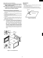
Figure C-3. Oven lamp socket
POWER SUPPLY CORD REPLACEMENT
Removal
5. Wind the conductor of the blue wire lead of the power
supply cord and the conductor of the wire lead of the
main wire harness each other.
6. Insert them into the connector. And clamp it.
7. CARRY OUT 4R CHECKS.
1. CARRY OUT 3D CHECKS.
2. Remove the one (1) screw holding the green/yellow wire
to the bottom plate right.
3. Disconnect the brown wire lead of the power supply cord
from the fuse holder.
4. Cut away the connector.
5. Release the power supply cord from the rear cabinet.
6. Now, the power supply cord is free.
Blue wire lead of power supply cord
15 mm
Re-install
Wire lead of the
main wire harness
1. Insert the moulding cord stopper of power supply cord
into the square hole of the rear cabinet.
2. Install the earth wire lead of power supply cord to the
bottom plate rirgt with one (1) screw and tight the screw.
3. Connect the brown wire lead of power supply cord to the
fuse holder correctly, referring to the Pictorial Diagram.
4. Strip the blue wire lead of the power supply cord and
white wire lead of the main wire harness for 15mm lengh
from their end.
Connector
CE-230
Conductor:
Stripped portion
Connector
CE-230
Figure C-4. Power supply cord replacement
1ST. LATCH SWICTH, 2ND. INTERLOCK RELAY CONTROL SWITCH AND MONITOR SWITCH REMOVAL
1. CARRY OUT 3D CHECKS.
2. Disconnect wire leads from the switches.
3. Remove two (2) screws holding latch hook to oven
flange.
4. Remove latch hook assembly from oven flange.
5. Push outward on the two (2) retaining tabs holding each
switch in place.
6. Switches are now free. At this time switch lever will be
free, do not lose it.
Re-install
1. Re-install each switch and switch lever in its place.
The 1st. latch switch and monitor switch are in the lower
position and 2nd. interlock relay control switch is in the
upper position.
2. Re-connect wire leads to each switch.
Refer to pictorial diagram.
3. Secure latch hook (with two (2) mounting screws) to
oven flange.
4. Make sure that the monitor switch is operating properly
and check continuity of the monitor circuit. Refer to
chapter "Test Procedure" and Adjustment procedure.
1ST. LATCH SWICTH, 2ND. INTERLOCK RELAY CONTROL SWITCH AND MONITOR SWITCH ADJUSTMENT
If each switch does not operate properly due to a
misadjustment, the following adjustment should be made.
1. Loosen the two (2) screws holding latch hook to the oven
cavity front flange.
2. With door closed, adjust latch hook by moving it back and
forth, and up and down. In and out play of the door
allowed by the upper and lower position of the latch hook
should be less than 0.5mm. The vertical position of the
21
R-3S68
4. Re-install outer case and check for microwave leakage
around door with an approved microwave survey meter.
(Refer to Microwave Measurement Procedure.)
latch hook should be adjusted so that the 1st. latch
switch 2nd. interlock relay control switch are activated
with the door closed. The horizontal position of the latch
hook should be adjusted so that the monitor switch is
activated with the door closed.
3. Secure the screws with washers firmly.
4. Check the operation of all switches. If any switch has not
activated with the door closed, loosen screw and adjust
the latch hook position.
LATCH HOOK
2ND. INTERLOCK
RELAY CONTROL
SWITCH
LATCH
HEADS
After adjustment, check the following.
1. In and out play of door remains less than 0.5mm when in
the latched position. First check upper position of latch
hook, pushing and pulling upper portion of door toward
the oven face. Then check lower portion of the latch
hook, pushing and pulling lower portion of the door
toward the oven face. Both results (play in the door)
should be less than 0.5mm.
2. The 1st. latch switch and 2nd. interlock relay control
switch interrupt the circuit before the door can be opened.
3. Monitor switch contacts close when door is opened.
MONITOR
SWITCH
SWITCH
LEVER
1ST. LATCH
SWITCH
Figure C-5. Latch Switch Adjustments
DOOR REPLACEMENT
REMOVAL
1. Disconnect oven from power supply.
2. Push the open button and open the door slightly.
3. Insert an putty knife (thickness of about 0.5mm) into the
gap between the choke cover and corner portion of door
frame as shown Figure C-6 to free engaging parts.
4. Try the principles of the lever and lift up the choke cover
by inserting a putty knife as shown Figure C-6.
5. Release choke cover from door panel.
6. Now choke cover is free.
7. Release two (2) pins of door panel from two (2) hole of
upper and lower oven hinges by lifting up.
8. Now, door panel is free from oven cavity.
9. Remove the two (2) screws holding the door panel to the
door frame.
10.Release door panel from nine (9) tabs of door frame by
sliding door panel downward.
11.Now, door panel with sealer film is free.
12.Tear sealer film from door panel.
13.Now, door panel is free.
14.Slide latch head upward and remove it from door frame
with releasing latch spring from door frame and latch
head.
15.Now, latch head and latch spring are free.
16.Remove door screen from door frame by releasing two
(2) tabs.
17.Now, door screen is free.
10
9
11
8
12
7
Choke Cover
1
Putty Knife
6
2
5
4
3
Door frame
Figure C-6. Door Disassembly
RE-INSTALL
1. Re-install door screen to door frame by fitting two (2) tabs
of door frame to two (2) holes of door screen.
2. Re-install latch spring to the head. Re-install latch spring
to the door frame. Re-install latch head to the door frame.
3. Re-install door panel to door frame by fitting nine (9) tabs
of door frame to nine (9) holes of door panel.
4. Hold the door panel to the door frame with two (2)
screws.
5. Put sealer film on door panel. Refer to "Sealer Film"
about how to handle new one.
6. Catch two (2) pins of door panel on two (2) hole of upper
and lower oven hinges.
7. Re-install choke cover to door panel by pushing.
22
R-3S68
SEALER FILM
Note: After any service to the door;
(A) Make sure that door sensing switch and secondary
interlock switch are operating properly. (Refer to
chapter "Test Procedures".).
(B) An approved microwave survey meter should be
used to assure compliance with proper microwave
radiation emission limitation standards.
Installation
1. Put the adhesive tape on the backing film of the sealer
film as shown in Fig. C-8.
2. Tear the backing film by pulling the adhesive tape.
3. Put the pasted side of the sealer film on the door panel
Sealer film
After any service, make sure of the following :
1. Door latch heads smoothly catch latch hook through
latch holes and that latch head goes through centre of
latch hole.
2. Deviation of door alignment from horizontal line of cavity
face plate is to be less than 1.0mm.
3. Door is positioned with its face pressed toward cavity
face plate.
4. Check for microwave leakage around door with an
approved microwave survey meter. (Refer to Microwave
Measurement Procedure.)
Note: The door on a microwave oven is designed to act as
an electronic seal preventing the leakage of
microwave energy from oven cavity during cook
cycle. This function does not require that door be airtight, moisture (condensation)-tight or light-tight.
Therefore, occasional appearance of moisture, light
or sensing of gentle warm air movement around
oven door is not abnormal and do not of themselves,
indicate a leakage of microwave energy from oven
cavity.
Backing film
Adhesive tape
Figure C-8. Sealer film
PIN
UPPER
OVEN HINGE
DDOR PANEL
CHOKE
COVER
PIN
LOWER
OVEN
HINGE
Figure C-7. Door Replacement
23
R-3S68
MICROWAVE MEASUREMENT
After adjustment of door latch switches, monitor switch
and door are completed individually or collectively, the
following leakage test must be performed with a survey
instrument and it must be confirmed that the result meets
the requirements of the performance standard for microwave oven.
2.
3.
REQUIREMENT
The safety switch must prevent microwave radiation emission in excess of 5mW/cm2 at any point 5cm or more from
external surface of the oven.
PREPARATION FOR TESTING:
Before beginning the actual test for leakage, proceed as
follows;
1. Make sure that the test instrument is operating normally
as specified in its instruction booklet.
Important:
Survey instruments that comply with the requirement for
instrumentations as prescribed by the performance
standard for microwave ovens must be used for testing.
4.
5.
6.
Recommended instruments are:
NARDA 8100
NARDA 8200
HOLADAY HI 1500
SIMPSON 380M
Place the oven tray into the oven cavity.
Place the load of 275 ± 15ml of water initially at 20 ±
5˚C in the centre of the oven tray. The water container
should be a low form of 600 ml beaker with inside
diameter of approx. 8.5cm and made of an electrically
non-conductive material such as glass or plastic.
The placing of this standard load in the oven is important
not only to protect the oven, but also to insure that any
leakage is measured accurately.
Close the door and turn the oven ON with the timer set
for several minutes. If the water begins to boil before the
survey is completed, replace it with 275ml of cool water.
Move the probe slowly (not faster that 2.5cm/sec.)
along the gap.
The microwave radiation emission should be measured
at any point of 5cm or more from the external surface of
the oven.
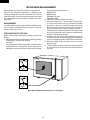
SHARP
mW cm 2
mW cm 2
Microwave leakage measurement at 5 cm distance
24
BLU
THERMAL CUT-OUT
95˚C (FAN)
2ND. INTERLOCK RELAY
CONTROL SWITCH
25
1ST. LATCH
SWITCH
Figure O-2. Oven Schematic-Cooking Condition
MAGNETRON
POWER TRANSFORMER
MONITOR
RESISTOR
0.8/20W
N.O.
H.V. RECTIFIER
TTM
TTM
FM
H.V. RECTIFIER
CAPACITOR
1.07µ
AC2100V
MONITOR SWITCH
TURNTABLE MOTOR
FAN MOTOR
OL
CONTROL
UNIT
A5
A1
MAGNETRON
POWER TRANSFORMER
MONITOR
RESISTOR
0.8/20W
RY-1
RY-2
THERMAL
CUT-OUT
145˚C
(OVEN)
THERMAL
CUT-OUT
145˚(MG)
FUSE
M8A
2ND.
INTERLOCK
RELAY
N.O.
CAPACITOR
1.07µ
AC2100V
MONITOR SWITCH
TURNTABLE MOTOR
FM
B2
B1
A3
OVEN LAMP
2ND. INTERLOCK RELAY
CONTROL SWITCH
FAN MOTOR
OL
A1
COM.
RY-1
RY-2
THERMAL CUT-OUT
95˚C (FAN)
2ND.
INTERLOCK
RELAY
THERMAL
CUT-OUT
145˚C
(OVEN)
EARTH
G-Y
BRN
220 V ˜ 50Hz
COM.
OVEN LAMP
CONTROL
UNIT
A5
THERMAL
CUT-OUT
145˚(MG)
FUSE
M8A
BLU
SCHEMATIC
NOTE: CONDITION OF OVEN
1. DOOR CLOSED
2. CLOCK APPEARS ON DISPLAY
B2
B1
A3
EARTH
G-Y
BRN
220 V ˜ 50Hz
R-3S68
NOTE: " " indicates components with potentials above 250V.
1ST. LATCH
SWITCH
Figure O-1. Oven Schematic-OFF Condition
SCHEMATIC
NOTE: CONDITION OF OVEN
1. DOOR CLOSED
2. COOKING TIME PROGRAMMED
3. START KEY TOUCHED
H
1
2
CN-B
3
26
4
RED
CN-A
1
CN-A
COM.
GRY
WHT
1ST
LATCH
SWITCH
(OVEN SIDE)
5
GRY
WHT
GRY
GRY
MONITOR
RESISTOR
TURNTABLE
MOTOR
BLK
ORG
GRY
RED
RED
WHT
RED
WHT
BRN
FUSE
M8A
LIVE
BRN
BLU
NEUTRAL
HIGH VOLTAGE
TRANSFORMER
G
/
Y
EARTH
POWER
SUPPLY
CORD
HIGH
VOLTAGE
CAPACITOR
HIGH VOLTAGE
WIRE B
RED
WHT
5
D
6
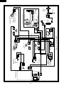
Figure S-1. Pictorial Diagram
RED
BLK
RED
THERMAL
CUT-OUT
(MAGNETRON)
WHT
WHT
MAGNETRON
HIGH VOLTAGE COMPONENTS
NOTE:
Live (RED) wire must be
connected to the terminal
with blue mark on the
oven light socket.
BLUE MARK
4
COM.
NO
WHT
MONITOR SWITCH
N.C.
GRY
WHT
BLK
3
5
G
5
4
3 GRY
2
1 ORG
THERMAL CUT-OUT
(FAN)
E
GRN
GRN
GRY
WHT
BLK
2
RY2
CN-B
GRY
GRN
BLK
RED
FAN MOTOR
1
2 GRN
1 GRY
COM.
N.O.
F
BLK
CONTROL UNIT
2ND INTERLOCK
RELAY CONTROL
SWITCH
B
OVEN LAMP
AND SOCKET
A
H.V.
RECTIFIER
C
THERMAL CUT-OUT
(OVEN)
R-3S68
6
A
B
C
D
E
F
G
H
3
27
DOOR SWITCH
4
B1
B2
a
c
VRS1
NOTE :
COM
A1
NO
POWER
TRANSFORMER
OVEN LAMP
TURNTABLE
MOTOR
FAN MOTOR
A5
b
d
10G471K
5
11ES1 x 2 C4
D2 D3
C4~5
100µ/35v x 2
RY2
RY1
2
4
D20
D30
Q21
KRC243M
5
IF NOT SPECIFIED, 0.01µF/16v
3
–
+
C2 47µ/16v
Q40
KRA101M
Q1
LM7905CT
1
–
+
IC1 IZA677DR
R82 100k
R81 100k
R80 100k
Q63
Q62
Q61
Q60
CF1
4MHz
Q60~63
KRA222M
Q64
KRC101M
SW5
1
MIN.
INSTANT
COOK
START
SW8
KEY SHEET
POWER
LEVEL
SERVE
SW7
AUTO COOK AUTO DEFROST
SW4
SW2
10
MIN.
SW1
10
SEC.
STOP
CLEAR
SW6
SW3
VC
R60 150
SERVE
CHECK
DEF
g
4 3 2 1 a b c d e f g h i
COOK
LIGHT EMITTING DIODE
5
Figure S-2. Contrl Panel Circuit
R31 4.7k
R20 15k
C6 0.1µ/50v
VC
Q2
KRA101M
CONTROL UNIT
4
IF NOT SPECIFIED, 1SS270A
2
Q20
KRA101M
Q22
KRA223M
–
+
Q10
KRA101M
C5
–
+
IF NOT SPECIFIED, 1/4w ± 5%
D21
AC220V
50Hz
(J1)
3
C10 0.01µ/50v
1
C30 0.1µ/50v
D1 : S1NB10
SP40
T1
D22
C1 470µ/16v
C21
10µ/35v
C11
C20
0.1µ/50v
R30 15k
ZD1
HZ4A-2
R10 15k
R40 3.3k
C3
(J2)
(J3)
2
15
H
20
–
25
1
+
–
14 VSS
R52
R51
R50
10 AIN3
R42
R41
R40
R72
5 PULSE
R70
RESET
XIN
1 XOUT
G
+
28
E
R53
R60
R61
R62
R63
INT2
R81
R82
R83
R90
R91
R92
KE0
VDD
F
R1 15k
D
R61 150
R62 150
R63 150
R64 150
R65 150
R66 150
R67 150
R68 120
C
3
D58
B
C12 0.1µ/50v
A
2
D57
1
D56
A3
R-3S68
6
A
B
C
6
D
E
F
G
H
R69 3.3k
R-3S68
1
2
4
3
13
5
6
1
A
A
Lot No
B
Q64
E
Q2
7
8
6
E
R69
C13
C12
ZD1
1
E
E
E
R68
R30
C3
(J2)
DIP
28
R1
R64
R65
R66
R67
SW3
D57
SW2
B
B
D56
D58
SW1
5
E
3
4
R63
R62
R61
B
R60
,F
1
2
9
CF1
B
Q63
B
Q62
B
Q61
B
Q60
11
SW4
12
14
IC1
13
C
10
C
15
14
(J3)
C6
R10
R20
C15
15
16
17
R80
R81
18
D
D
R82
R31
SW5
19
20
E
21
B
Q40
C11
B
Q10
E
C10
C30
22
23
E
E
SW7
SW6
SW8
24
25
C8
C14
26
27
28
29
30
31
32
C7
33
E Q22
B
C5
34
B
C4
Q21
D2
SP40
D3
C21
E
C2
C1
D1
Q1
F
R40
F
B
C20
D20
Q20
35
D21
1
5
E
36
G
G
RY1
RY2
4
2
3
T1
(J1)
D22
2
VRS1
CN - B
H
CN - A
LEAD
WIRE
1
D30
5
LEAD WIRE
GREEN
1
POWER
3
OL TTM FM
H
Figure S-3. Printed Wiring Board
1
2
4
3
28
5
6
R-3S68
PARTS LIST
Note: The parts marked "∆" may cause undue microwave exposure.
The parts marked "*" are used in voltage more than 250V.
REF. NO.
PART NO.
DESCRIPTION
1- 1
1- 2
1- 3
1- 4
1- 5
1- 6
1- 7
1- 8
1- 9
1-10
1-11
1-12
1-13
1-14
1-15
1-16
1-17
QSW-MA110WRE0
QSW-MA111WRE0
RV-MZA197WRE0
RTHM-A080WRE0
FH-DZA047WRK0
RC-QZA172WRE0
RMOTEA265WRE0
RTHM-A072WRE0
QACC-A065WRE0
QFS-CA010WRE0
QFSHDA019WRE0
QSOCLA022WRE0
RLMPTA069WRE0
RMOTDA169WRE0
RR-WZA003WRE0
RTRN-A480WRE0
QPLGAA018WRE0
1st. latch and 2nd. Iinterlock relay control switches
Monitor switch
Magnetron
Thermal cut-out 145˚C
High voltage rectifier assambly
High voltage capacitor
Cooling fan motor
Thermal cut-out 95˚C
Power supply cord
Fuse (M8A)
Fuse holder
Oven lamp socket
Oven lamp
Turntable motor
Monitor resistor
0.8Ω
20W
Power transformer
AC plug
2222-
GCABUA522WRT0
FDAI-A171WRY0
GDAI-A261WRW0
GLEGPA019WRE0
Outer case cabinet
Bottom plate right
Bottom plate left
Foot
Q'TY
CODE
2
1
1
2
1
1
1
1
1
1
1
1
1
1
1
1
1
AK
AK
BN
AP
AQ
AY
AZ
AM
AS
AE
AH
AG
AK
AW
AG
BP
AL
1
1
1
4
AT
AT
AP
AD
1
1
1
1
1
1
2
1
1
1
1
1
1
1
1
1
2
3
1
3
1
1
1
1
1
1
1
1
1
4
1
1
1
1
1
1
1
8
1
1
3
1
1
1
8
BH
AC
AB
AB
AA
AH
AB
AC
AB
AH
AC
AM
AB
AC
AD
AG
AB
AA
AA
AA
AN
AV
AE
AB
AB
AB
AB
AB
AB
AB
AB
AA
AA
AA
AA
AA
AA
AA
AA
AA
AA
AG
AK
AG
AB
ELECTRICAL PARTS
∆ *
*
*
*
CABINET PARTS
1
2
3
4
CONTROL PANEL PARTS
3- 1
3- 1A
3- 1B
C1
C2
C3
C4-5
C6
C10
C11
C12
C20
C21
C30
CF1
D1
D2-3
D20-22
D30
D56-58
IC1
LED
Q1
Q2
Q10
Q20
Q21
Q22
Q40
Q60-63
Q64
R1
R10
R20
R30
R31
R40
R60-67
R68
R69
R80-82
RY1
RY2
SP40
SW1-8
CPWBFA687WRK0
QCNCMA234DRE0
QCNCMA275DRE0
VCEAB31CW477M
VCEAB31CW476M
VCKYD11CY103N
VCEAB31VW107M
RC-KZA132DRE0
VCTYF31HF103Z
VCKYD11CY103N
RC-KZA132DRE0
VCEAB31HW104M
VCEAB31VW106M
RC-KZA132DRE0
RCRS-A012DRE0
RSRCDA013DRE0
VHD11ES1///-1
VHD1SS270A/-1
VHD1SS270A/-1
VHD1SS270A/-1
RH-IZA677DRE0
VHPSL3965T/1B
RH-IZA401DRE0
VSKRA101M//-3
VSKRA101M//-3
VSKRA101M//-3
VSKRC243M//-3
VSKRA223M//-3
VSKRA101M//-3
VSKRA222M//-3
VSKRC101M//-3
VRD-B12EF153J
VRD-B12EF153J
VRD-B12EF153J
VRD-B12EF153J
VRD-B12EF472J
VRD-B12EF332J
VRD-B12EF151J
VRD-B12EF121J
VRD-B12EF332J
VRD-B12EF104J
RRLY-A078DRE0
RRLY-A083DRE0
RALM-A014DRE0
QSW-PA016DRE0
Control unit
3-pin connector (A)
2-pin connector (B)
Capacitor
470uF 16V
Capacitor
47uF 16V
Capacitor 0.01uF 16V
Capacitor
100uF 35V
Capacitor
0.1uF 50V
Capacitor 0.01uF 50V
Capacitor 0.01uF 16V
Capacitor
0.1uF 50V
Capacitor
0.1uF 50V
Capacitor
10uF 35V
Capacitor
0.1uF 50V
Ceramic resonator (CST4.00MGW)
Diode bridge (S1NB10)
Diode (11ES1)
Diode (1SS270A)
Diode (1SS270A)
Diode (1SS270A)
LSI
Light emitting diode (SL-3965T-01)
Integrated circuit (LM7905CT)
Transistor (KRA101M)
Transistor (KRA101M)
Transistor (KRA101M)
Transistor (KRC243M)
Transistor (KRA223M)
Transistor (KRA101M)
Transistor (KRA222M)
Transistor (KRC101M)
Resistor
15k ohm 1/4W
Resistor
15k ohm 1/4W
Resistor
15k ohm 1/4W
Resistor
15k ohm 1/4W
Resistor 4.7k ohm 1/4W
Resistor 3.3k ohm 1/4W
Resistor
150 ohm 1/4W
Resistor
120 ohm 1/4W
Resistor 3.3k ohm 1/4W
Resistor 100k ohm 1/4W
Relay (OJ-SH-118LM)
Relay (OMIF-S-118LM)
Buzzer (PKM22EPT)
Tact switch (SKHVBD)
29
R-3S68
Note: The parts marked "∆" may cause undue microwave exposure.
The parts marked "*" are used in voltage more than 250V.
REF. NO.
T1
VRS1
ZD1
3- 2
3- 2-1
3- 3
3- 4
3- 5
PART NO.
RTRNPA088DRE0
RH-VZA032DRE0
VHEHZ4A2///-1
FPNLCB223WRK0
PSHEPA559WRE0
JBTN-A921WRF0
MSPRCA050WRE0
XEPSD30P08XS0
DESCRIPTION
Transformer
Varistor (10G471K)
Zener diode (HZ4A2)
Control panel frame with key sheet
Key sheet
Open button
Open button spring
Screw; Control unit mtg.
PHOK-A095WRF0
LBNDKA095WRP0
NFANJA029WRE0
PDUC-A599WRP0
FOVN-A333WRT0
LANGFA171WRP0
MLEVPA194WRF0
NCPL-A045WRF0
PCOVPA275WRE0
PCUSGA339WRP0
PCUSUA329WRP0
PDUC-A597WRF0
PFILWA041WRE0
PPACGA084WRF0
LANGQA368WRP0
LANGQA343WRP0
PCUSGA378WRP0
PCUSGA388WRP0
PCUSUA278WRP0
Latch hook
Capacitor holder
Fan blade
Fan duct
Oven cavity
Chassis support
Switch lever
Coupling
Waveguide cover
Cushion
Cushion
Air guide
Lamp filter
TTM packing
Fuse angle
Thermal cut-out (Fan) mounting angle
Cushion
Cushion
Cushion
Q'TY
1
1
1
1
1
1
1
8
CODE
AT
AH
AA
AX
AQ
AF
AB
AA
1
1
1
1
1
1
1
1
1
1
1
1
1
1
1
1
1
1
1
AN
AM
AL
AK
BD
AG
AG
AH
AR
AG
AC
AG
AF
AF
AL
AK
AL
AK
AC
1
1
1
1
1
1
1
2
2
AY
AH
AM
AN
AQ
AF
AB
AB
AA
1
1
1
1
1
1
1
1
1
1
1
1
1
1
1
1
AQ
AR
AR
AL
AH
AW
AF
AB
AC
AM
AC
AB
AA
AZ
AK
AG
9
2
3
1
14
9
1
1
AA
AA
AA
AA
AA
AA
AA
AA
OVEN PARTS
∆ 4- 1
4- 2
4- 3
4- 4
∆ 4- 5
4- 6
4- 7
4- 8
4- 9
4-10
4-11
4-12
4-13
4-14
4-15
4-16
4-17
4-18
4-19
DOOR PARTS
∆ 555∆ 55∆ 5555-
1
2
3
4
5
6
7
8
9
FDORFA283WRT0
PSHEPA382WRE0
GCOVHA342WRF0
GWAKPA348WRR0
HPNL-A586WRE0
LSTPPA139WRF0
MSPRTA084WRE0
PCUSUA452WRP0
XCPSD40P06000
Door panel
Sealer film
Choke cover
Door frame
Door screen
Latch head
Latch spring
Cushion
Screw; 4mm x
6- 1
6- 2
6- 3
6- 3
6- 4
6- 5
* 6- 6
6- 7
6- 8
6- 9
6-10
6-11
6-12
6-13
6-14
6-15
FROLPA057WRK0
NTNT-A051WRE0
TINS-A565WRR0
TINS-A564WRR0
FW-VZB045WRE0
FW-VZB494WRE0
QW-QZA150WRE0
LHLDWA011WRE0
TCAUHA214WRR0
PSHE-A068WRR0
TSPCNC322WRR0
PZET-A012WRE0
QTANP0020YBE0
TCADCA565WRR0
QW-QZA177WRE0
TLABPA032WRR0
Roller stay
Turntable tray
Operation manual (English)
Operation manual (Thai)
Switch harness
Main wire harness
High voltage wire B
Purse lock “M”
Caution label
Menu label
Name plate
Terminal insulator
Connector
Cook book (Thai)
Earth wire
Grounding label
77777777-
XFPSD40P08K00
XFPSD30P06000
XHTSD40P08RV0
XHTSD40P08000
XOTSD40P12RV0
XOTSD40P12000
XVPSD40P20000
XFPSD30P10000
Screw : 4mm x 8mm
Screw : 3mm x 6mm
Screw : 4mm x 8mm
Screw; 4mm x 8mm
Screw : 4mm x 12mm
Screw : 4mm x 12mm
Screw; 4mm x 20mm
Screw; 3mm x 10mm
6mm
MISCELLANEOUS
SCREWS,NUTS AND WASHERS
1
2
3
4
5
6
7
8
30
R-3S68
HOW TO ORDER REPLACEMENT PARTS
To have your order filled prompty and correctly, please furnish the following information.
1. MODEL NUMBER
3. PART NO.
2. REF. NO.
4. DESCRIPTION
PACKING AND ACCESSORIES
TOP PAD ASSEMBLY
FPADBA311WRK0
DOOR PROTECTION SHEET
SPADPA204WRE0
PLASTIC BAG
SSAKHA034WRE0
VIDEO TAPE
OPERATION MANUAL
COOK BOOK
WARRANTY CARD
BOTTOM PAD ASSEMBLY
FPADBA312WRK0
INTO THE
OVEN CAVITY
TURNTABLE TRAY
ROLLER STAY
TRAY PAD
SHRINK WRAP BAG
SPADFA257WRE0
PACKING CASE
SPAKCC764 WRE0
Not replaceable items.
31
R-3S68
2
1
4
3
6
5
7-5
OVEN AND CABINET PARTS
7-5
6-2
2-1
A
A
7-5
1-13
1-12
6-1
4-13
7-5
B
B
1-4
4-12
7-1
6-8
4-11
C
C
7-6
1-3
6-10
7-6
6-15
7-6
D
4-19
4-5
D
7-6
6-14
7-3
A
1-17
1-9
E
E
4-8
4-10
7-5
1-5
1-1
7-1
4-9
7-2
1-4
7-5
4-14
1-6
7-1
4-18
1-2
4-6
F
4-1
2-3
1-14
7-1
4-7
4-2
4-3
F
7-6
1-1
4-15
6-11
7-4
7-1
x2
7-3
4-4
1-10
7-6
1-16
G
4-17
7-3
1-15
2-4
G
7-8
7-7
1-9
7-5
1-11
A
7-1
1-7
4-16
1-8
7-2
2-2
7-5
H
H
2-4
7-6
1
2
7-5
4
3
32
5
6
R-3S68
2
1
CONTROL PANEL PARTS
4
3
6
5
3- 1
3- 2
A
A
3- 5
B
B
3-2-1
DOOR PARTS
C
C
5-2
3- 3
5-3
5-9
5-1
3- 4
D
D
5-8
5-4
5-5
5-9
E
E
5-8
5-6
5-7
F
F
MISCELLANEOUS
6-5
6-4
G
G
Actual wire harness may be different from illustration.
6-7
6-6
6-12
H
H
1
2
4
3
33
5
6
R-3S68
'96SHARP CORP. (3U0.07E) Printed in Japan
34