1
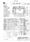
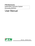
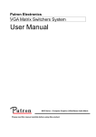
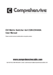
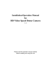
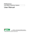
Digimax 210
Programmable Thermostat
User Guide
Schema of the thermostat
The RF DigiMax 210 thermostat does not need any extra
wiring and works within 30 meters range around the receiver
RF-Max. The DigiMax 210 is equiped of a secured RF code
which the RF Max will learn during the installation process.
This code will assure that the receiver will only answer to
messages sent by your DigiMax 210. This process is described at the end of this manual.
I. To start :
Remove the battery insulation strip and check unit is functioning.
II. Operation :
The DigiMax 210 Digital Room thermostat is simple to use.
The Liquid Crystal Display continuously shows ambient temperature.
To change the “Set Point” (i.e. temperature requested), press
and hold the “SET” key and at the same time press “+” or “-”
to select the temperature setting. The display will show the
“Set Point” until the “SET” button is released. The display will
then show the ambient temperature.
When the DigiMax 200 instructs your heating system to switch
on, a small flame symbol appears at the bottom right of the
display.
III. Installation :
DigiMax 210 Technical Data
Temperature Range :
Differential :
Ambient temperature :
Power Supply :
Switch :
Battery Life :
Maintenance :
RF range :
5°C to 35°C in 1°C steps
16°C to 35°C selectable
<1°C at 4K per Hour
Operating 0°C to 45°C
3 type AA 1.5 v alkaline cells
230v ac 2 (1)A
2 years Typical
no user maintenance required
30 meters
Please read all installation instructions before proceeding.
The RF DigiMax 210 works with batteries. It does not need
any wire. If you wish it to replace an old cable thermostat,
isolate and secure the old wires, which are useless now. Do
not forget to cut the power when you take off the old thermostat.
IV Position
The ideal position to locate the DigiMax 210 Digital Room
Thermostat is about 1.5m above floor level, accessible, free
from extremes of temperature and draughts. Do not mount
on an outside wall, above a radiator or where it may be subjected to direct sunlight.
The radio link does not mean that the wiring has been simplified, but that the thermostat can be installed in any place of
your house to optimate your needs in heating.
We recommend you to make the installation with the receiver
RF-Max before fixing your thermostat on the wall, in order to
be certain of its good operation at the selected place.
V Fixing
1 The wall plate should be positionned with a minimum of
70 mm clearance all round to allow adequate air flow
2 Fix the wall-plate directly to a flat wall
3 Remove the battery insulation strip and check unit is functioning, place it on its wall-plate
VI Configuring
The unit is supplied with a 5°C minimum temperature set
point and configured as a heating thermostat as factory defaults. Two internal links can be used to reconfigure these
defaults.
1 Open the unit by slackening the retaining screw situated in
the bottom edge and hinging carefully upwards. Disengage the unit from the wall-plate and place it to one side
for safe keeping.
2 Locate and identify the two option Links 1 and 2. Use a pair
of small wire cutters to cut the appropriate links to give the
required configuration.
3 Cutting Link 1 will give a minimum temperature set point
of 16°C (factory default is 5°C). Cut link 2 to display cooling
symbol instead of heating symbol.
4 Replace batteries being sure to observe the correct
polarities. Re-fit to plastic base and tighten retaining screw.
Check unit is functioning as required.
VII Battery replacement
A “flashing” battery low symbol will appear at the bottom left
of the display when the batteries start to approach the end of
their life. This indicates that they should be replaced within
the next month. Ultimately, the display will start flashing and
the thermostat will shut down until the batteries are replaced.
To replace the batteries, the following procedure should be
carried out. The thermostat should be isolated from the mains
before proceeding.
1 Slacken the retaining screw on the unit and open by hinging upwards the top edge.
2 Remove batteries and fit two new “AA” alkaline cells taking
care to observe the correct battery polarities. Check unit is
functioning
3 Re-fit it to the plastic base and check that the RF link still
operates. This can be easily done by adjusting the
requested temperature under or over the level of the
ambient temperature, in order to activate and disactivate
several times the boiler while watching the green LED on
the RF-Max receiver.
RF DigiMax 210 Rear View
Link 2
Link 1
Batteries
3 2 1
Terminal block
Cut Link 1 for 16°C minimum set point
Cut Link 2 to display cooling symbol
instead of heating symbol
RF link between the Thermostat RF DigiMax 210
and the RF-Max
a) Commissioning
The RF DigiMax 210 is required to be matched with the RFMax receiver. This is to ensure only the correct thermostat is
controlling your ambient temperature. The thermostat sends
a signal which is a unique code (1 of 65000), which only the
matched RF-Max receiver is capable of understanding. From
this moment, the RF-Max will only answer to signals sent by
this thermostat
RF Receiver Led’s (indicators) :
Red Led :
‘flashing’ :
‘steady on’ :
indicates receiving an RF signal
indicates a fault condition e.g. RF signal
not being received
‘slowly plusing’ : indicates a valid install code has been
received
Green Led :
‘steady on’ : - indicates demand for heat
‘off’ :
- no demand for heat i.e. heating call
satisfied
b) Checking the hard wired circuit :
1. Rely the RF-Max receiver to the mains. Check that no thermostat in the heating network request warm. The red LED
should be off.
2. Press the Test button. The Green Led should come on.
Check that the boiler and/or motorised valve have been
operated. Remember to allow adequate time for the valve
to open. Press Test button again. The green led should
go out closing any valve and switching off the boiler.
Nota : the thermostat automatically leaves the test mode
after 15 minutes.
c) Checking the RF circuit
1. To install thermostat with the RF receiver press and hold
the OK and COPY keys together in Auto mode for 3
seconds. The DigiMax 210 will then transmit its unique
digital code every 10 seconds for the next 5 minutes. The
display will show flash ‘]]]’ while this is happening.
2. Within the 5 minute install period go to the RF-Max Receiver. Press and hold the Install button and then press
the Test button while the Install button is held. This will
clear out any previously installed codes. The Red Led will
pulse slowly for 3 seconds to indicate this has been done.
3. Next, place the Receiver in Install mode by pressing and
holding the Install button (for at least 10 seconds). The
Red LED will come on and stay on until a valid Install
Code has been received. When this happens the Red
LED will start pulsing slowly and the install button can
then be released. The Red LED will pulse for a further 5
seconds and then go off. The Install code has been
successfully received.
4. Go to the Thermostat Transmitter and press any key to
stop the transmission. The display will stop flashing ‘]]]’
and return to normal.
5. The R-Max Receiver will now only respond to radio signals with the installed code i.e. from the DigiMax 210 Thermostat just installed. Even if the power is removed from
the Receiver it will not forget the installed code.
6. Check that the DigiMax 210 and the RF-Max are communicating with each other by adjusting the Digimax 210
Thermostat set point above or below the actual temperature thus generating a radio signal. This will happen every
time the DigiMax 210 Thermostat calls for heating / cooling to be switched on or off.
7. The DigiMax 210 Thermostat also sends a radio signal
every 5 minutes to make sure that the RF-Max Receiver
knows what state it should be in. Therefore every 5 min-
utes the Red LED will flash for 3 seconds. If the RF-Max
does not receive regular RF signals the Red LED will
come full on indicating that a fault condition has occured
and the heating system will be switched off.
Note : If more than one “Thermostat RF- RF Receiver” is
installed with the same caracteristics, it is important to apply
the above process for each thermostat, in order to be sure
that each thermostat is connected to the right receiver.
c) Trouble shooting
1. Red LED stays full on :
This may indicate that the batteries need to be replaced or
that there is an interference with another radio signal.
2. Installation :
If nothing happens after 20 continuous seconds of
pressing of the Install button of the receiver, check that the
thermostat transmits its radio signal (the symbol ]]] flashes
on the display of the thermostat)
3. Minimum temperature level :
If while adjusting the set point it is found that it cannot be
set below 16°C check with the installer that the unit has
not been configured to restrict the minimum set point (this
often required for installations in sheltered accomodation).
See ‘Configuring’ in the installation guide of how to reconfigure the unit.
4. Trouble shooting
If the heater does not operate when the thermostat is
asking for warm, check the battery indicator and changes
the battery units if necessaru. If the indicator has vanished,
remplace the piles for you have probably missed the signal
indicating weak battery. If the batteries are taken out during
more than 5 - 10 minutes, it maight be necessary to make
again the installation with the RF-Max receiver
Extending the SC9000 security console with a Digimax 210 thermostat.
The HF DigiMax 210 thermostat does not require extra wiring and has a radius of 30 m. The appliance is
equipped with a protected HF code. This code is registered with the SC9000 during installation. This code
ensures that the SC9000 will only respond to messages sent by your DigiMax 210. You can register up to
4 DigiMax 210 thermostats with the SC9000. Depending on the information sent out by the thermostat, the
SC9000 Marmitek X10 transmits ON and OFF signals via the mains, to switch the Marmitek X10 modules
connected to your boiler on or off. You can set a “differential temperature” in the SC9000, which lies
between 1 and 9 degrees. If the SC9000 is set to "Disarm" or "Arm Home", the X10 module connected to
your boiler will be switched on or off, depending on the comfort temperature set. If the SC9000 is set to
"Arm Away", the “differential temperature” setting will come in effect. Example: the room temperature is 15
°C, the comfort temperature set is 20 °C, with a "differential temperature" of 4 °C -> 20 °C – 4 °C = 16 °C:
this means the appliance will transmit a “turn on” command, until the temperature has reached 16 °C.
Registering a thermostat
1. To access the menu, press the menu Ĺ or menu Ļ button. The display will now read [ENTER PIN]
2. Enter your 4-digit PIN code (factory setting 0000.). For every digit, an asterisk (*) will appear on the
display.
3. If the PIN code has been entered correctly, the word INSTALL will appear on the display.
4. Press OK.
5. To register the thermostat with the console, keep both the + and – button of the thermostat pressed in
for 3 seconds. The DigiMax 210 will transmit the unique digital code every 10 seconds, during a period of
5 minutes. The display will flash and show the symbols “[[[“. The console will beep to confirm. The display
will read "STAT 1 OK".
Remove a registered thermostat
If you are using multiple thermostats, you can only remove all thermostats. Then you have to re-register
the thermostats you want to use.
1. To access the menu, press the menu Ĺ or menu Ļ button. The display will now read [ENTER PIN]
2. Enter your 4-digit PIN code (factory setting 0000.). For every digit, an asterisk (*) will appear on the
display.
3. If the PIN code has been entered correctly, the word INSTALL will appear on the display.
4. Press OK.
5. Use the buttons menu Ĺ/Ļҏ to scroll to menu item 6: [MEMORY CLEAR] Press OK to select this item.
You can also go directly to item 6 by pressing the 6 on the keyboard.
6. Use the buttons menu Ĺ/Ļҏ to scroll to menu item [CLEAR ALL THERMOSTATS] Press OK to select this
menu item.
7. The display will now read [CONFIRM CLR 1. YES 2. NO] Press 1 to confirm and erase the thermostats.
The thermostats have now been unregistered.
How does the console work with the Digimax 210?
The SC9000 transmits a X10 message on the unit code corresponding to the zone number of the console
and the house code of the console +3. In the factory setting, the house code of the console is set to A:
- thermostat in zone 1 will generate X10 messages on code B3,
- thermostat in zone 2 will generate X10 messages on code B4,
- thermostat in zone 3 will generate X10 messages on code B5,
- thermostat in zone 4 will generate X10 messages on code B6.
Example: You have set the house code for the console to B,
- thermostat in zone 1 will generate X10 messages on code C3,
- thermostat in zone 2 will generate X10 messages on code C4,
- thermostat in zone 3 will generate X10 messages on code C5,
- thermostat in zone 4 will generate X10 messages on code C6.
Extending the SC9000 security console with a Digimax 210 thermostat.
If the console has not received any more messages from the thermostat, the LCD display will read
[PROBLEM ZONE X]
Programming the “differential temperature” on the console
The thermostat needs to be registered with the SC9000 to be able to view the Setback settings in the
OPTIONS menu (7).
1. To access the menu, press the menu Ĺ or menu Ļ button. The display will now read [ENTER PIN]
2. Enter your 4-digit PIN code (factory setting 0000.). For every digit, an asterisk (*) will appear on the
display.
3. If the PIN code has been entered correctly, the word INSTALL will appear on the display.
4. Press OK.
5. Use the buttons menu Ĺ/Ļҏ to scroll to menu item 7: [OPTIONS] Press OK to select this item. You can
also go directly to this item by pressing the 7 on the keyboard.
6. Use the buttons menu Ĺ/Ļҏ to scroll to menu item SETBACK. Press OK to select this menu item.
7. The display will now read SETBACK x DEG C. Enter the differential temperature. This can be set from
01 to 09 degrees. Press OK. The display will now read the new differential temperature.
Activating the “differential temperature” remotely
If the security console SC9000 is in “Arm Away” mode, you can use your phone to choose to activate the
temperature or not:
Make sure the dial-in function is activated (menu [OPTIONS/ANSWER TYPE])
1. Ring the security console from a land line or mobile phone.
2. The security console will respond to your call with “Please enter pin”.
3. Enter your PIN code via the buttons on your phone (standard setting is 0000).
4. The security console will respond to a correctly entered PIN code with “PIN accepted” (when entering
an incorrect PIN code you will hear ”ERROR”).
5. Press “88#” on your phone to activate the differential temperature. You will hear “Thermostat set back”
as a confirmation.
6. The “differential temperature” is now activated (the differential temperature is deducted from the comfort
setting).
To deactivate the “differential temperature”
Make sure the dial-in function is activated (menu [OPTIONS/ANSWER TYPE] ).
1. Ring the security console from a land line or mobile phone.
2. The security console will respond to your call with “Please enter pin”.
3. Enter your PIN code via the buttons on your phone (standard setting is 0000).
4. The security console will respond to a correctly entered PIN code with “PIN accepted” (when entering
an incorrect PIN code you will hear ”ERROR”).
5. Press “88*” on your phone to deactivate the differential temperature. You will hear “Thermostat normal”
as a confirmation.
6. The “differential temperature” is now deactivated (the differential temperature is no longer deducted
from the comfort setting).