1
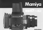
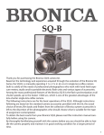
Congratulations on your purchase
of a Mamiya RZ67 PRO II
The Mamiya RZ67 PRO II is the latest and most advanced model
of Mamiya's famous 6 x 7 cm SLR camera series, distinguished by
their Revolving Back and rack and pinion Bellows Focusing.
The result of Mamiya's long experience and accomplishments in
the professional medium format camera field, it combines
mechanical perfection with the latest opto-electronic technology.
Complimented by its large selection of world-class Mamiya lenses
and many other system accessories, the RZ67 has become the
camera of choice of the world's top photographers.
The RZ67 PRO II is a versatile camera, ideally suited for many
photographic applications, including commercial, portrait, fashion,
industrial, nature and scientific photography.
In order to take full advantage of its capabilities and to insure
proper operation, please read this instruction manual carefully
before you use your new camera.
Contents
Special Features of the Mamiya RZ67 PRO II ..............2
Nomenclature and Functions ...........................................4
Mamiya RZ67 PRO II Specifications ............................ 10
The Revolving Back ............................................................. 29
Distance Scale • Depth-of-Field ........................................ 30
Long Exposures ................................................................... 31
Inserting the Battery ........................................................ 11
Attaching / Removing Lenses ........................................ 12
Using the Waist-Level Finder ......................................... 14
Multiple Exposures • Infrared Photography ..................... 32
Mirror Lock-up Operation .................................................... 33
Flash Photography • Using a Tripod ................................. 34
Interchanging the Focusing Screen .............................. 16
Releasing the Shutter .................................................... 17
Shutter Speed and Aperture .......................................... 21
Close-up Photography ........................................................ 35
Attaching a Lens with
Shutter Released or Mirror Raised ................................... 36
The Roll Film Holder ........................................................ 22
Loading the Film Holder .................................................. 24
Taking Photographs ........................................................ 27
Camera Back Lock System ................................................ 37
How to Use the Carrying Strap .......................................... 38
Troubleshooting ................................................................... 39
Unloading Exposed Film ................................................. 27
Focusing and Locking the Focusing Knob ................... 28
Using RB Series Lenses and Accessories ...................... 40
Care of the Camera ............................................................. 41
1
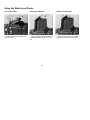
Special Features of the Mamiya RZ67 PRO II
1. The Ideal Format
3. Rack and Pinion Bellows Focusing
The 6x7 cm format is called the ideal format because it
enlarges to the standard 8x10" paper size without cropping,
thus utilizing the entire image area. The 6x7 format of the RZ
PRO II (actual image size is 56x69.5mm) is almost 5x larger
than a 35mm frame and offers far superior image quality for
enlargement or full page magazine reproduction. 6x7
transparencies can be viewed on the light table without
magnifiers.
Bellows focusing, another great advantage, permits precise
focusing with the left or right hand and also features a focus
lock lever. The RZ PRO II has an additional micro focus knob
for precise fine focusing. The camera bellows eliminate the
extra costs of equipping each lens with a helical focusing
mount and permits close-up photography without costly
attachments. (The closest focusing distance of the 110mm lens
is 31.3cm, the 65mm wide angle lens 8.5cm and the 180mm is
84.5cm).
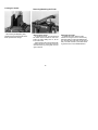
2. Mamiya Revolving Back with Automatic
4. World-Class Mamiya Lenses
Finder Masking
Mamiya world-class lens quality is a major reason for the top
reputation of Mamiya camera. Mamiya operates its own
modern optical design, engineering and manufacturing plant
and accepts undivided responsibility for the perfect
performance of its cameras and lenses. The RZ67 PRO II
camera features a large diameter 61mm lens mount which
makes it possible to design a variety of high performance
lenses, such as APO, Shift and Zoom.
With a flip of the wrist, the Revolving Back-a Mamiya
exclusive among 6x7 SLRs-can be rotated for horizontal or
vertical format without changing the optical axis. At the same
time it also automatically changes the masking frame in the
finder to match the format. Other cameras require removing
and reattaching film holders when changing format or having
to turn the camera on its side which complicates viewing and
operation.
2
interfaces electronically, through gold plated contacts, with
the camera body, AE Prism Finder FE701 and RZ lenses.
You set the dial when you load the film and never have to
worry about correct meter indexing.
5. Bright, Interchangeable Finders and
Focusing Screens
A Waist Level Finder FW702 with self-erecting focusing hood
and magnifier is factory supplied with each camera.
The eye-level AE Prism Finder FE701 is an important
accessory. It features three-way metering (average, spot or
auto shift) and computerized, aperture-priority shutter control,
compatible with the intermediate shutter speeds. It can also
be operated manually. Exposure compensation to +/- 3EV and
AE Lock are other features. All RB67 finders can also be
used.
6. Interchangeable
8. Mirror Lock-up operation
Locking the mirror in the up position eliminates all
possible vibrations and is especially important in close-up
and telephoto work, when slow shutter speeds are required.
9. Multiple Exposures
Multiple exposures are easy with a flip of a switch. No
removal of film holder is required.
Film Holders with Maximum
Film Flatness.
10. New Features
Available for 120 or 220 films and made in 6x7, 6x6 and
6x4.5 formats. Also Polaroid holder. The film holders can be
quickly interchanged, even in mid-roll. Two film counter
windows permit easy reading as film holders are rotated on
cameras' revolving back.
Dark slide storage drawer is another feature.
• Modern, functional design
• Rugged interior mechanisms
• Intermediate shutter speeds
• Micro focusing knob.
• Roll Film Holders with dual exposure counters
• "RBL" shutter speed dial setting when using RB67 lenses.
7. Electronic Interface
The ISO film speed dial is located on the film holders and
3
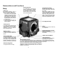
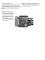
Nomenclature and Functions
Focusing Screen
Body
The visible field of the focusing
R-M Lever
For normal operation, lever is
aligned with center index mark.
"M": For making Multiple Exposures set it to "M". This will disengage the film transport when
cocking the shutter. Do not forget to return it to center position afterwards. This setting is
also used to exercise the camera without film.
"R": Turning the lever to "R" unlocks and permits rotating the
Revolving Back.
screen automatically changes
from vertical to horizontal format,
or vice-versa, as the revolving
back is rotated. The screen it self
is also interchangeable.
Gold Plated Contacts
Interface AE Prism Finder electronically with camera, lens and
film holder.
When using an RB67 PD Prism
Finder or PD Magnifying Finder
on the RZ PROII , be sure to first
attach the small plastic cover,
which comes packed with the RZ
PROII , over the contacts. (See
instructions packed with cover).
Lens Alignment Dot
Cocking Lever
In a single operation this lever advances the film, cocks the shutter,
and sets the mirror. For proper
operation, be sure to push the
lever completely down.
Do not touch the mirror under any
circumstances.
Distance Scale
Auxiliary Electronic Shutter
Release Contacts
A single scale indicating distance
in meters and feet is used for all
lenses.
Sliding the cover upwards reveals
its contacts.
Mirror
Shutter Release Button
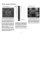
Focal Length Scale
Curved lines representing most focal lengths appear on this scale.
The point at which the appropriate
focal length curve intersects the
Distance Graduation indicates the
distance focused upon by the lens.
Dual Focusing Knob
For regular and fine focusing.
Collar Stop Lever
This safety feature prevents the
Release Button Collar from
Release Button Collar
For normal operation the white dot (❑) on the Release But- being rotated to the orange dot
ton Collar is kept aligned with the white dot on the Collar until the Collar Stop Lever is first
Stop Lever. Aligning the white dot of the collar with the red depressed.
dot on the camera body locks the Shutter Release Button.
Aligning the collar with the orange dot makes it possible to
operate the shutter at approximately 1/400 sec. without
batteries in the camera.
4
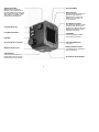
Shutter Speed Dial
Alignment Mark
Speeds from 8 to 1/400 sec.
Between 4 and 1/250 sec. there
are intermediate settings with click
stops. When set to "AEL" or "RBL"
dial is locked. To release press
center button. (See page 21)
Revolving Ring
Its small orange circle clicks into
place and must always be
aligned with the orange index
marks in the 12 o'clock or 3
o'clock positions.
Film Advance Coupler
The central pin transmits a signal
to the film holder which disengages the film advance-stop and
activates the multiple exposure
prevention mechanism.
Carrying Strap Lug
Lock Release Button
Light Baffle
To avoid damaging the baffle
and camera, do not touch.
Hot-Shoe
Film Holder Mount Pin
Focusing Knob Lock Lever
One of four.
Battery Chamber Cover
Winder Coupler Cover
The camera use a 6 V alkaline or
silver oxide battery.
Tripod Socket
The socket has standard U 1/4"
threads which can be removed
and converted to a 3/8" socket.
Contacts for Power Winder
5
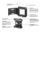
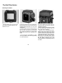
Waist-Level Finder
Roll Film Holder
Magnifier Release
To raise the magnifier, push the
Magnifier Release to the left.
Alignment Mark
Magnifier
Interchangeable with other magnifiers in various diopter strengths.
Dark Slide Release Pin
Holder Lock Pin
The upper and lower holder lock
pins prevent the holder from
coming off position when
mounted on the camera body.
Film Advance Knob
Dual Exposure Counter
Features vertical and horizontal
windows.
Memo Clip
Finder Release Button
Holds the film box top as a filmtype reminder or a memo.
To remove the finder, Push in on
both (right and left) release
buttons and lift the finder off
camera body.
Dark Slide Storage Slot
Finder Catch
6
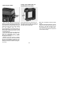
Film Speed Dial
Used to set the ISO speed of
the film used.
Back Cover Latch
Dark Slide
A safety feature prevents the
shutter from being released
unless the Dark Slide is first
removed. Make it a habit to first
remove the Dark Slide before
attempting to take a photograph.
Lock Release Lever
Use this lever when removing
the roll film holder when the
dark slide has been pulled out.
Spool Release Pins
Holder Lock Lever
Depress these pins to insert or
remove film.
Should one inadvertently attempt
to remove the Film Holder without
first inserting the Dark Slide, the
Holder Lock Lever will not unlock,
thereby preventing accidental exposure of the film.
Film Spool Stud
A new roll of film is loaded on
this stud with the paper leader
pulled over the roller in the
direction indicated by the dotted
line and arrow which appears
around the stud.
Take-up Spool
After removing an exposed roll
of film, place the empty spool in
this position.
Start Mark
The start mark on the backing
paper must be aligned with this
mark.
7
Bayonet Ring
Lens
The Bayonet Ring is a breech
mount which secures the lens on
the camera body. As a safety
feature, the lens can not be
removed from the camera body
unless the mirror is set (lowered),
thereby assisting the Light Baffle
in shielding the film from light.
Flash Sync Terminal (X-sync)
Knob for turning Depth of
Field Calculating Ring
Can be set for meters or feet.
Depth-of-Field Scale
Lens Distance Scale
Depth-of-Field Preview
Aperture Ring
Time Exposure Lever
Mirror Lock-up Cable
Release Socket
Shutter Lock Pin
If a lens is not to be used over a
prolonged period, it is desirable
to store it with the shutter
released. In order to release the
shutter of a lens which has been
removed from the camera body,
rotate the Shutter Cocking Pins
clockwise while depressing the
Shutter Lock Pin.
To lock mirror up for vibration free
photography follow this sequence:
Camera mirror and lens is in
cocked position. Screw a cable
release into this socket. You will
notice that a chrome collar rises
and shows a red ring. Depress the
body release. This will now only
move the mirror up and hold it
there. Now fire shutter with cable
release.
Cocking Position Marks
Shutter Cocking Pins
When manually cocking the
shutter, be sure to rotate the
Shutter Cocking Pins as far as
they will go (i.e.. to the red dot)
8
Mamiya RZ67 PRO II Specifications
Focusing Method: The Rack and pinion focusing extends the built-in bellows
up to a maximum of 46 mm /Equipped with a Focusing Knob
and Lock Lever/ With subject distance and exposure factor
indications.
Winder
:RZ Winder II (RZ Winder I cannot be used)
Cable release contact:The shutter can be released by mean of a cable
release connected to a contact on the camera body / Remote
control is possible by means of a receiver connected to the
same contact.
Battery Type: One alkaline-manganese battery (4LR44) or silver oxide Battery (4SR44) to operate the body / Six AA size Ni-Cd
batteries or one special AC adapter (DC9V) for driving the winder.
Safety features (in normal shutter release operation):
• Viewfinder display (by LEDs and pictorial symbols):
Warning on incomplete cocking lever setting / Warning on failure
to pull out the dark slide / Battery check.
• Electronic alarm sound when : The shutter speed dial is at the "RBL" position
when an RZ lens is used /The shutter dial is at the "AEF" position
when the AE Prism Finder is removed / The shutter speed dial is
any other position than "RBL" when no lens is mounted or an RB
lens is mounted on the camera / The battery power has dropped.
• Release locked when : The cocking lever has been set incompletely / The dark
slide has not been pulled out / The shutter speed dial is at the
"RBL" position when an RZ lens is used /The shutter speed dial is
at the "AEF" position when the AE Prism Finder is removed / The
shutter speed dial is at any other position than "RBL" when there
is no lens on the body or an RB lens is mounted on the camera.
Dimensions
:108 mm (width) X133.4 mm (height) X 211.5 mm (length).
Weight
:2,490g when the body (1,350g) (with Waist-Level Finder), 120
Roll Film Holder (530g) and 110 mm f/2.8 lens (610g) are
combined.
Camera Type :6 X 7 cm roll film SLR with lens shutter.
Film Holder :120 Roll Film Holder HA703 ---the standard holder
] interchangeable
220 Roll Film Holder HB702
6x4.5 120 Roll Film Holder RZ
Polaroid Pack Film Holder HP702
Film type
:120 film (120 Roll Film Holder HA703) (10 exposure) /120 film
(6x4.5 120 Roll Film Holder RZ) (15 exposures) /220 film (220
Roll Film Holder HB702) (20 exposure) / Instant film (Polaroid
Pack Film Holder HP702)
Negative size:6x7 cm format: 56x69.5 mm / 6x4.5 cm format: 56x41.5 mm /
Polaroid Pack: 70x70 mm
Revolving Back: The back revolves 90° to change from the horizontal to
vertical format or vice versa. Viewfinder format automatically
changes as back revolves.
Lens Mount :Special bayonet mount (with built-in safety lock)
Lens type
:110mm f/2.8---the Standard Lenses/ Interchangeable RZ
lenses/Interchangeable lenses for the RB can also be used.
Shutter
:Seiko #1 electronic shutter
Shutter release: Body shutter release plus electronic shutter release contacts.
Shutter speed:1/400-8 sec. (with intermediate speeds), B, T (mechanical) /
RBL (when the RB lens used) and AEF (when the AE Prism
Finders used) positions / Mechanical shutter of 1/400 sec.
usable.
Sync operation: with flash sync terminal (X-sync) on lens or hot shoe.
Multiple exposure: possible by means of R-M lever.
Focusing Screen: Type A Matte is the standard / Focusing screens for the RZ
are interchangeable.
Viewfinder
:Waist-Level Finder FW702 is the standard interchangeable with
the AE Prism Finder FE701 / Finders for the RZ and RB can also
be used.
Percentage of the field of view visible:95% This information is based on a
linear (horizontal / vertical) measurement.
Film Transport:A single 114° stroke of the Cocking Lever advances the film
and Exposure Counter, sets the Mirror and Light Baffle, and
cocks the shutter.
• Specifications and appearance are subject to change without notice.
10
Inserting the Battery
• Even if battery power is depleted, aligning
the Release Button Collar with the orange dot
will make it possible to release the shutter at
approximately 1/400 sec.
Because the Mamiya RZ67 Pro-II does not
function properly without a battery, be sure to
load one into the Battery Chamber before
attempting to use the camera.
The camera uses one of either of the following batteries:
4LR44 (6V alkaline manganese battery)
4SR44 (6V silver oxide battery)
2. Insert the battery into the chamber taking
care to match the + - poles of the battery
with those shown in the diagram found in
the chamber: match the - pole first. Future
extraction and replacement of the battery
will be simplified if the Battery Removal
Ribbon is placed under and over the battery.
Be careful though not to block the + - poles
with the ribbon.
1. Pull the finger catch on the Battery
Chamber Cover in the direction of the arrowhead to open it.
11
CAUTION:
1. Since the battery that comes with the camera was packed at the time of shipment, its
power may be depleted sooner than that of a
fresh battery. Therefore, please buy a new
battery at your earliest convenience.
2. Be sure to match the poles of the battery
with those shown in the diagram in the chamber.
3. Carefully wipe the contacts of the battery
before insetting it into the chamber. Failure to
do so could result in poor electrical contact
and cause erratic functioning of the camera.
4. When not using the camera for a long
period of time, remove the battery and store it
in a dry, cool place.
5. Battery life varies considerably in accordance with the following factors: battery type,
freshness of the battery when purchased, the
conditions under which the battery was stored
before purchase and how it is stored after
purchase, temperature at the time of use and
service frequency.
6. Silver oxide batteries have a longer battery
life than alkaline batteries.
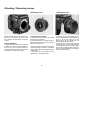
Attaching / Removing Lenses
Attaching Lenses
Before attaching a lens to the camera body,
the mirror in the body must be set in the
down position and the shutter of the lens
cocked.
Setting the Mirror
1. Remove the Body Cap from the camera.
2. Make sure the mirror is set (lowered). If
the mirror is in the up position, lower it by
pushing the Cocking Lever as far as it will go
toward the front of the camera body.
Cocking the Lens Shutter
1. Remove the Rear Lens Cap by rotating
the bayonet ring clockwise.
2. If the lens shutter is not cocked, firmly rotate the Shutter Cocking Pins as far as they
will go to the red dot “A”.
• Moving the Shutter Cocking Pins only as far
as the green dot will result in incomplete
shutter cocking. Be sure to rotate them as far
as the red dot.
• Whenever a lens is removed from the
camera body, it is already cocked.
12
Attaching the Lens
1. With the front of the lens facing you, rotate the Bayonet Ring counterclockwise as
far as it will go (the white dot on the
Bayonet Ring will be aligned with the
central index on the lens mount).
2. Seat the lens on the camera body with
the red index line on the lens mount facing
the red alignment dot of the camera body.
Next, rotate the Bayonet Ring of the lens
firmly in a clockwise direction, securing the
lens to the camera body.
Removing the Lens
1. Push the Cocking Lever of the camera
body completely down, which will set the
mirror and cock the lens shutter.
2. Rotate the Bayonet Ring of the lens
counterclockwise as far as it will go (the
white dot on Bayonet Ring will align with
central red index line of lens) and remove
the lens.
To release the shutter on a lens which has
been removed from the camera body, rotate
the shutter cocking pins “B” clockwise as far
as they will go, while depressing the shutter
lock pin “A”.
• If you try to rotate the Bayonet Ring
counterclockwise without first depressing
the Cocking Lever of the camera body, the
movement of the ring will be blocked,
making it impossible to remove the lens.
This safety feature assures that the mirror
must always be lowered whenever the lens
is removed, thereby assisting the Light
Baffle in shielding the film from light.
13
CAUTION:
When attaching/removing the lens, be sure
not to rest the camera on its back unless either a roll film holder or the back protective
cover is attached. This is necessary to prevent damage to its various spring loaded
function pins.
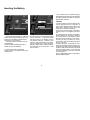
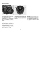
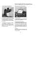
Using the Waist-Level Finder
Raising the Finder
Raising the Magnifier
Lowering the Magnifier
Merely lift the back of the Finder until it
opens completely.
Slide the Magnifier Release slightly to the
left and the Magnifier will pop up into position.
Gently push the base plate of the Magnifier all the way down until it locks in place.
14
Folding the Finder
Removing/Attaching the Finder
After lowering the Magnifier, gently
squeeze the right and left panels of the
finder together while closing it.
Removing the Finder
Attaching the Finder
To remove the Finder, push the right and
left release buttons towards the rear of the
Finder and while holding them in, lift the
front of the Finder.
These release buttons are equipped with
a safety mechanism so that they cannot be
removed merely by pushing them from the
right or left side.
To attach the Finder, slide the Finder
Catches into the groove of the camera body,
and while holding in both Finder Release Buttons, seat the front of the finder on the camera
body. The finder will lock in place after releasing pressure from on the Release Buttons.
15
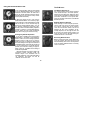
Interchanging the Focusing Screen
Interchanging the Magnifier
To remove the Magnifier, gently squeeze
the magnifier frame with the sides of the finder
and rotate the Magnifier counterclockwise.
To attach the Magnifier, align the white dot
on the Magnifier frame, and rotate the Magnifier clockwise.
• The Magnifier is interchangeable. In addition
to the standard (-1.5 diopter) lens, +1, 0, -1,
-2 and -3 diopter lenses are also available.
Please note that plus lenses are for
far-sighted and minus lenses are for
near-sighted individuals.
Removing the Focusing Screen
Focusing Screens
There are seven instantly interchangeable
focusing screens to choose from, each designed for specific applications.
Removing a Focusing Screen
After removing the focusing hood, lift up
and remove the screen by grasping the lug on
the right-hand side (as viewed from the back
of the camera). To replace a screen, gently
lower the left-hand side of the screen (as
seen from the camera back), followed by the
right-hand side, and lightly snap screen into
place.
CAUTION
When removing screens, exercise care not to
touch the vertical and horizontal format
viewfinder masks.
16
Releasing the Shutter
It is best to become acquainted with the
method of releasing the shutter before
using film in the camera.
1. Rotate the Release Button Collar until
the white dot on it is aligned with the
one immediately below (on the Collar
Stop Lever).
2. Remove the Dark Slide.
3. Set the R-M Lever to the "M"
(multiple exposure) position.
4. Set the shutter speed dial to any
speed except "AEF" and "RBL".
5. Push the Cocking Lever all the way
down.
6. Press the Shutter Release Button.
* The first 4 steps can be done in any order.
After you are thoroughly familiar with the
above steps, return the RM Lever to its
normal setting (the center position).
17
Using the Release Button Collar
The R-M Lever
The Normal Position (❏)
1. For normal operation, align the white square
“B” on the Release Button Collar “A” with the
white dot on the lever below ”B”. When this is
done, the Shutter Release functions electromagnetically and the various safety mechanisms operate electrically.
For normal operation of the camera, the R-M
Lever should be kept in the center position,
aligned with the index mark. Setting the lever
to this position activates the double exposure
prevention mechanism so that photo after
photo can be taken without fear of accidental
double exposures.
2. When the camera is not in use, lock the
Shutter Release Button. This is done by aligning the white dot of the Release Button Collar
with the red dot “C” on the camera body. By
locking the Shutter Release Button, you not
only prevent unintentional exposure of film,
but also prevent accidental battery depletion
caused by pressure on the Release Button.
For this reason, be sure to lock the Release
Button when carrying the camera in a bag.
Multiple Exposure Position
When desiring to make multiple exposures,
set the R-M Lever to the 'M' position. When
this is done, pushing down on the Cocking
Lever will cock the lens shutter, but will not
advance the film. Upon completion of the
multiple exposure, do not forget to return the
R-M Lever to its normal (center) position. The
lever can also be set to 'M' when testing the
shutter without film in the camera.
*Emergency Shutter Operation
If you were to suddenly find yourself with a
dead battery in the midst of a photographic
session, switch over to the emergency shutter
operation mode. In order to do so, push the
Collar Stop lever “D” toward the camera body
and while holding it there align the white dot of
the Release Button Collar with the orange dot
“E” on the camera body. The shutter will now
operate (even without a battery) at approximately 1/400 sec., regardless of the setting of
the Shutter Speed Dial.
Because electricity is not being used in the
emergency shutter operation mode, the
Monitor Lamps in the viewfinder will not
illuminate. Moreover, even if the Dark Slide is
not withdrawn, the shutter can still be
released, so exercise care.
Revolving Back Position
Before revolving the back, set the R-M Lever
to the "R" position. After this is done, the lever
will automatically return to the normal position
when the Shutter Release Button or Cocking
Lever is next used.
18
LED Monitor Lamp and Electronic Warning Sounds
Operating the Cocking Lever
When depressing the Cocking Lever, be sure to push it all the way
forward (toward the Shutter Release Button). If the Cocking Lever is
not pressed forward as far as it will go, it will return to its original
position when released, but the shutter will not be cocked. At such a
time, shutter will not operate and an orange warning lamp will
illuminate in the viewfinder when the Shutter Release Button is
depressed.
Note:
It may happen that when attaching the
Roll Film Holder, or after having rotated
the holder attached to the revolving back,
the film advance coupling mechanisms
between camera and holder may not
properly mesh. In this case the shutter
cannot be fired when the release is
pressed and the orange warning lamp will
light in the viewfinder.
By moving the "M/R" lever to "R" and
pushing the cocking lever slightly, the
couplings will mesh and the release button will function again.
19
The following page will explain the visual and audio signals which
are built into the camera and which are designed to assure proper
operation and to prevent mistakes.
Electronic Warning Sounds
LED Monitor Lamps in Finder
There are three monitor lamps visible on the rear
edge of the finder. They will indicate the following
conditions when the shutter release is depressed:
If the dark slide is withdrawn, the release is depressed
but the shutter will not fire and a beeping warning sound
is heard, the following conditions may exist:
The speed dial is set on "AEF" but:
• the AE Finder or an RZ lens is not attached.
• An RB lens is mounted to camera.
Red Lamp
Attach an AE Finder and RZ lens, or:
Change speed dial away from "AEF" and conform speed dial to
match lens on camera.
(i.e. "RBL" when RB lens is on camera.)
: When it glows it indicates that:
• The dark slide has not been withdrawn.
• The camera battery is good.
When the dark slide is withdrawn the light will go out.
• If then the monitor lamp blinks, accompanied by
the electronic warning sound, it shows that the battery is weak and should be replaced.
The speed dial is set on "RBL" but:
• an RZ lens is attached.
Either mount an RB lens, or change shutter speed dial away from
"RBL"
Battery Condition
When the red monitor lamp blinks accompanied by the beeping
warning sound, the battery is low.
Orange Lamp: When it glows it indicates that:
• The cocking lever has not been advanced or
• The roll film holder has not been advanced.
(Does not apply when in multi exposure "M" mode.)
Replace the battery.
Maximum 1 minute "B" exposure.
• When the shutter release is depressed for about 55 sec. a
warning sound will be heard and the shutter will close after 5
sec.
• The same applies at "B" setting with mirror up photography.
Green Lamp : When the Metz/Mamiya Interface Module SCA 395
is attached to the flash shoe and connected to certain
Metz flash units, this LED will glow to indicate that the
unit is flash ready.
20
Shutter Speed and Aperture
The Shutter Speed Dial
Select the shutter speed desired and rotate
the Shutter speed Dial until the appropriate figure is aligned with the shutter speed index
mark. Usually, the Shutter Speed Dial must be
set to a click-stop position. However, it can
also beset to an intermediate speed. The numerals as they appear on the dial and the
shutter speeds they represent are shown in
the following table. When the Shutter Speed
Dial is set to "B"(bulb), the shutter will remain
open as long as pressure is applied to the
Shutter Release Button and will close as soon
as pressure is released. The AEF mark which
appears on the Shutter Speed Dial is the
setting for the AE Finder.
When set at this position, the dial locks in
place. To unlock it, rotate the dial while depressing the Lock Release Button which appears in the center of the dial. The RBL mark
on the dial is setting for taking photos using
the RB67 lenses. In other positions the shutter
release button will not released.
The Aperture Ring
Using RB67 Lenses on RZ PRO II Body
As stated before, the camera speed dial
must set to RBL and the shutter speed on
the lens. In addition you must consider that
the flange focal distance on RB lenses is
111 mm and on RZ lenses 104 mm. Therefore with RB lenses the bellows must be
moved forward by 7 mm to focus on infinity.
The distance scales cannot be used. Shutter release is identical to RZ lens operation.
21
To set the diaphragm to a desired aperture, rotate the Aperture Ring until the appropriate figure is aligned with the central
index line. It is perfectly acceptable to use
the Aperture Ring at in-between click-stop
settings. When the Shutter Release Button
is depressed, the diaphragm will automatically stop down to the preselected aperture
before the shutter opens for the exposure.
The Roll Film Holder
Attaching the Holder
1. Slide the Holder Lock Lever of the Roll
Film Holder completely toward the Lock
Release Lever “A”.
2. Align the orange circle “B” of the Revolving
Ring (found at the rear of the camera) with one
of the two white index marks “C” or “D” on the
camera body.
3. Hold the Holder so that its orange circle is at
the same position as the one on the Re-volving
Ring “B” and fit the holder onto the camera
back, making sure that the four Camera Back
Mount Pins fit into the four openings of the
holder.
• Do not touch the Light Baffle or mirror.
Touching the Baffle could result in light leaking
in or other malfunction.
22
4. Lock the holder to the camera body by
moving the Slide Lock as far as it will go as
indicated by the arrow.
• Make sure that the holder securely couples
with the camera body; otherwise light may
leak in and cause film damage.
Because of the revolving back feature,
attaching the roll film holder to the camera
requires a little practice. We find that a good
method is to place the bottom edge of the
holder against the bottom edge of the body,
(preferably while resting on a flat surface)
letting the top of the holder leave a slight
gap, permitting you look down and to match
the two bottom mounting pins of the
revolving back to the corresponding holes of
the holder.
Removing the Holder
Insert the Dark Slide into the Roll Film
Holder. For instant recognition, the Dark Slide
Slot is bordered by white reference lines. The
Film Holder can be removed after moving the
Holder Lock Lever as far as it will go toward
the Lock Release Lever “A”. It is
recommended that you remove the holder on a
table or similar support, or in your lap, to avoid
the possibility of dropping the holder or having
it fall off the camera.
If you attempt to remove the holder without
replacing the Dark Slide, the Holder Lock
Lever will automatically lock in place,
preventing accidental removal of the holder
and exposure of the film.
However, if you must remove the holder
without the Dark Slide in place, the automatic
lock can be overridden by pulling the Lock
Release Lever toward the Holder Lock Lever,
holding the lever there, and then moving the
Lock Lever.
Pulling out the Dark Slide of a
Detached Roll Film Holder
When detached from the camera body, the
Dark Slide cannot be pulled out. However, if
you wish to remove it, push in the pin “A” on
the holder with a pointed object.
23
Note: Non-Compatibility of Roll Film Holder
Inserts.
While all model RZ and RZ PRO II roll film
holders can be used with both the RZ and
RZ PRO II , this does not apply to the
interchangeability of the film holder inserts.
They can only be used with their respective
roll film holder housings.
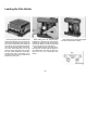
Loading the Film Holder
Pull out the upper and lower Back Cover
Latches and the back cover will open. Because of the double safety lock, pulling out
just one of the two Back Cover Latches will
not open the cover. After opening the back
cover of the Roll Film Holder, remove the
Film Insert. When loading film, it is not necessary to remove the holder from the camera back. When loading film, avoid direct
sunlight--either load in the shade or turn
your body away from the sun and use the
shade of your own body.
While holding down the left-hand Spool
Release Pin of the Film Insert, fit a roll of film
between the upper and lower left-hand Film
Spool Studs. Make sure that the backing paper is set as shown in the photo above.
When loaded correctly, the inside of the
backing paper (the black side) will appear on
the outside of the insert back. If it does not,
remove the film, turn it upside-down, and
reload .
24
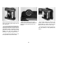
After feeding the tip of the backing paper
into the slot of the Take-up Spool,
gently wind the Film Advance Knob until the
arrow of the backing paper aligns with the
insert Start Mark.
Place the Film Insert into the housing,
making sure the film advance coupler of the
insert fits into the appropriate hole of the
cassette.
As your gently advance the backing paper,
make sure it advances evenly between the
spool flanges and does not begin to slant. If
it advances unevenly, remove the backing
paper from the Take-up Spool and re-insert.
Heeding this point will eliminate the
possibility of crimping the edge of the film.
After correctly placing the insert into the
housing, close the back cover, and while
gently holding it in place, push both of the
Back Cover Latches as far as they will go.
The Roll Film Holder Housing will accept either 120 (HA703) or 220 (HB702) Film
Inserts.
Set the correct film speed value on the
Film Speed Dial of the Roll Film Holder.
25
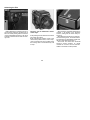
Advancing the Film
Before attempting to advance the film to
the first frame, make sure the R-M Lever is
set to its normal (center) position. If the lever
is set to 'M'(multiple exposure), it will not be
possible to advance the film with the Cocking Lever.
The film can be advanced in either
of two ways.
A. By winding the Film Advance Knob of the
Film Insert until it stops.
B. By activating the Cocking Lever of the
camera body several times, until it stops.
(The lens shutter will not be cocked unless
the Cocking Lever is moved all the way until
it stops.
26
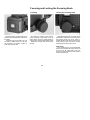
When the film is completely advanced, the
numeral '1' will appear in the Exposure
Counter, making the first frame ready for
exposure.
While advancing the film form S (start) to 1
with the Cocking Lever, the shutter releasing mechanism is automatically locked until
the film is fully advanced to frame 1.
Since there are vertical and horizontal
exposure counter windows, an upright
numeral can be seen with the Roll Film
Holder in horizontal or vertical position.
Taking Photographs
Unloading Exposed Film
When the film is advanced to the next
frame, the numeral in the Exposure
Counter will automatically change.
• CAUTION
120 or 220 film used in this roll film holder
is, unlike 35 mm film, not perforated.
Therefore, if it is advanced very rapidly,
the spacing between frames may become
uneven. So, be sure to gently operate the
cocking lever with even strokes to maintain
proper frame spacing.
After an exposure is made, the automatic
double exposure prevention mechanism
blocks the shutter release until the film has
been advanced.
After completing the last exposure, press
the Cocking Lever several times, until the
film and backing paper have been completely wound onto the Take-up Spool. Instead of using the Cocking Lever, you can
use the Film Advance Knob of the Film Insert, if you prefer.
Then open the back cover of the Film
Holder and remove the Film Insert.
While holding down the right-hand Spool
Release Pin, remove the film, making sure
that the backing paper does not unroll or
become loose.
To prepare for future use, remove the
empty spool from the Film Insert and move it
to the right-hand side so that it will act as the
new Take-up Spool.
When the back cover of the holder is
opened, the Exposure Counter will automatically return to 'S' (Start).
If anything other than 'S' appears in the Exposure Counter, it indicates that there is film in the
holder. To prevent accidental exposure of the film,
always check the Exposure Counter before
opening the back cover of the holder.
27
To process a partially exposed roll of film,
first insert the Dark Slide and remove the
holder. Next, while holding in the pin in the
center of the coupler “A”, completely wind
the film onto the Take-up Spool with the
Film Advance Knob. Instead of continuously
holding in the coupler pin, you can push it in
once after each frame, if preferred.
Focusing and Locking the Focusing Knob
Focusing
During exposures, the Dark Slide can be
stored in the Dark Slide Slot in the back of
the holder.
The Memo Clip on the back cover can
be used for holding the film box-top as a
film reminder or for holding a piece of
paper with pertinent data.
Locking the Focusing Knob
Depressing the Cocking Lever sets the
mirror, projecting a bright image on the focusing screen. Focus by rotating either Focusing Knobs until the image appears sharp.
Please use the large inner knob for fine
focusing.
After adjusting the focus, focus shift can be
prevented by locking the Focusing Knob with
the Focusing Knob Lock Lever, which is
located behind the left hand Focusing Knob.
Simply raise the lever and push it forward,
clamping the Focusing Knob in place.
Refocusing
If the focusing knob is moved accidentally
while it was not locked the image may be out
of focus. Also, be careful that you do not
touch the focusing knob at the down stroke of
the film transport lever.
28
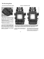
The Revolving Back
The Vertical and Horizontal Formats
Change in Viewfinder Format
Before attempting to revolve the back, set the
R-M Lever to "R". To change from horizontal
to vertical format, rotate the Film Holder
clockwise as far as it will go. Rotating it
counter-clockwise, changes the format from
vertical back to horizontal.
Revolve the back clockwise or counterclockwise until it securely clicks at a 90° turn. If
the back is not in a "click position", the shutter
release button will not function.
The R-M Lever will automatically return from
"R" to its normal position upon depressing the
Cocking Lever or Shutter Release Button.
However, as long as the R-M Lever remains at
the "R" setting, the Film Holder can inadvertently be moved off-center. Therefore we
recommend, returning the lever to its normal
position (i.e., center index mark) immediately
after revolving the back.
As the revolving back is rotated, the viewfinder format automatically changes from horizontal to vertical, or vice versa. This is accomplished by viewfinder masks which are coupled
to the revolving back. Additionally, when viewed from the top, a small rectangle appears at
the upper edge of the Film Holder, Visible at a glance, this rectangle acts as a reminder,
indicating whether the holder has been set for the vertical or horizontal format.
* Be sure to rotate the Film Holder gently, as
undue use of force can result in damage to
the camera.
29
*Do not revolve the back while pressing the
shutter release button. When using a cable
release or self-timer, the release end must
be correctly adjusted; otherwise the shutter
release button may remain depressed.
Distance Scale • Depth-of-Field
Distance Scale
The Distance Scale is used to determine
the film-plane-to-subject distance. The scale
itself is composed of two parts, the Distance
Scale and Focal Length Scale.
After focusing, the correct distance can be
determined by locating the point at which the
curved line for the focal length in use intersects the Distance Scale.
For example, if the 110 mm lens is
mounted on the camera and focused as
shown in the illustration, the subject is 1.5 m
(5 ft) from the film plane.
Depth-of-Field
Depth-of-Field Preview
1. Set the Aperture Ring to the desired f-stop
and focus the lens.
2. Depress the Depth-of-Field Preview Lever
of the lens and you will be able to check the
depth-of-field directly on the focusing screen.
30
Using the Depth-of-Field Scale
1. Check the camera-to-subject distance on
the Distance Scale.
2. Rotate the Lens Distance Scale Knob until
the previously noted camera-to-subject
distance is aligned with the center index of the
Depth-of-Field Scale.
3. Locate the selected aperture on both sides
of the Depth-of-Field Scale.
4. The figures of the Lens Distance Scale,
appearing above the selected aperture,
indicate the nearest and furthermost limits of
sharpness for that aperture.
For example, when the 110mm lens is
focused at 3 m and stopped down to f /32,
everything from approximately 2m to 10m will
be in focus.
When desiring to know the depth-of-field in
feet, rotate the Lens Distance Scale 180°, as
one side is in feet and the other in meters.
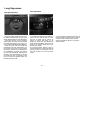
Long Exposures
Bulb (B) Exposures
When the Shutter Speed Dial is set to B,
the shutter will remain open as long as the
Shutter Release Button remains depressed.
Since bulb exposure is also controlled
electronically, the shutter will automatically
close after approximately one minute in order to prevent inadvertent battery depletion.
When using bulb, after the Shutter Release Button has been depressed for approximately 55 seconds, a warning buzzer
will sound. If pressure on the Release Button is maintained, the buzzer will continue
for about 5 seconds longer, after which the
electricity will be automatically cut off and
the shutter will close. If exposures longer
than one minute are required please, use
the time exposures mode.
Time Exposures
1. To make a time exposure, first slide the T
Lever of the lens until the letter "T" under
the lever is visible and the normal "N"
making is covered. After doing so, the
shutter will remain open upon depressing
the Shutter Release Button. At this time, the
setting of the Shutter Speed Dial on the
camera body ceases.
2. To close the shutter, slide the T Lever in
the opposite direction, exposing the letter 'N'
(normal), During time exposures, do not
touch the Cocking Lever until the shutter
closes.
31
• Since the shutter operates mechanically, not
electronically during a time exposure, there is
virtually no drain of battery power, and the
shutter speed dial can be set in any position
other than "RBL".
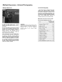
Multiple Exposures • Infrared Photography
Multiple Exposures
Infrared Photography
RZ lenses need no focusing mount because of the bellows feature. Normally,
lenses with focusing mounts have a secondary index for infrared film. Therefore, if you
want to do critical infrared photography, you
should focus as usual and before exposures
move the focus slightly towards the camera
body, as per table below. There is a
millimeter scale on top of the focus scale.
RZ67 PRO II Infrared Correction Table
Shows required adjustment at infinity
1. Set the R-M Lever to 'M' (multiple
exposure). The lever can be 100
moved to 'M' either before or after releasing
the shutter.
2. Press the Cocking Lever as far as it will go
in order to cock the shutter and set the mirror.
The film will not advance at this time. The
shutter can now be released, creating a
double exposure. This procedure can be
repeated as often as desired to create as
many exposures as necessary.
CAUTION
Unlike the "R" lever, the "M" lever does not return
automatically to its normal position. Therefore you
must do it manually. If you forget, the film is not
transported and not only are subsequent
exposures wasted, but the planned multiple
exposure also.
When photographing the same subject two or
more times though, exposure compensation
is necessary. The same is true with different
subjects that are all evenly illuminated. With
subjects of different brightness, the darker
one is normally photographed first. However,
it is not within the scope of this operating
manual to teach multiple exposure technique,
as many excellent books dealing with this
subject are already available.
32
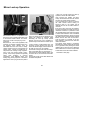
Mirror Lock-up Operation
With the RZ 67 PRO II , it is possible to lock
the mirror in the up position beforehand, and
at the desired instant release the shutter
without the usual accompanying mirror
movement.
Referred to as, "mirror lock-up operation," this
technique is extremely valuable when even
the slightest mirror vibration must be
eliminated. When the mirror rises, it usually
causes vibrations the very instant before the
shutter opens, creating a possible loss of
sharpness when working at high magnifications or with long shutter speeds. Consequently, mirror lock-up operation is especially
useful
when
engaging
in
close-up
photography, using telephoto lenses, and
making long ("slow") exposures. Yet another
application is when trying to catch the peak of
action. By raising the mirror beforehand, the
shutter can instantly be released, totally
eliminating the time lag usually present
between the time the mirror completes its
upward swing and the time the shutter opens.
1. After screwing a cable release firmly into
the Mirror Lock-up Socket of the lens, the
socket will elevate slightly and the camera will
be ready for mirror lock-up operation.
2. Press the Cocking Lever as far as it will go.
Step 2 may either follow or precede step 1.
3. Depress the Shutter Release Button and
the mirror will rise, but the shutter will remain
closed.
4. Press the plunger of the cable release and
the shutter will operate.
33
• When you no longer need mirror lock-up
operation, remove the cable release.
Upon removing the release, the Mirror
Lockup Socket will retract and the camera
will return to normal shutter operation.
If you complete step 3 above, but remove
the cable release without making an
exposure (step 4), the shutter will be
released as soon as the cable release is
removed.
Even when using mirror lock-up operation,
everytime the shutter is cocked, the mirror is
relowered. Therefore, it is possible to check
the viewfinder before each frame is exposed.
A double cable release is both an available
and convenient accessory. Since one end of
the release screws into the Shutter Release
Button and the other end into the Mirror
Lock-up Socket, it is possible to use the
same release to raise the mirror and later
release the shutter.
The double cable release is particularly
valuable when using B exposures with mirror
lock-up operation. After pressing the shutter
release button to raise the mirror, detach the
cable release from the mirror lock-up socket.
At that instant the shutter will be released.
-Continued on next page-
Flash Photography • Using a Tripod
Attaching Flash Units
CAUTION
• As long as a cable release remains attached to
the Mirror Lock-up Socket, the camera is set for
mirror lock-up operation.
Consequently, it will not be possible to take a
photography by merely pressing the shutter
release button.
• It the red line around the Mirror Lock-up Socket
is still visible when the cable release is removed,
the camera is still set for mirror lockup operation.
If such is the case, reattach the cable release,
making sure that the socket retracts as you
remove it once again.
• The shutter should be released with the cable
release within 55 seconds of pressing the Shutter
Release Button. If this is not done, the alarm will
sound after 55 seconds later and continue for 5
seconds before stopping.
• If you release the shutter with the cable release
after the alarm stops (approx. 60 seconds), the
shutter speed will be 1/400sec. If you wish to use
a shutter speed other than 1/400 sec. after the
buzzer stops, follow the procedure for multiple
exposure in the steps given below.
1.
Set the R-M lever to "M" (multiple
exposure),and press down the cocking lever.
2.
Set the shutter speed dial to a desired speed
and perform "mirror lock-up".
3.
Reset the R-M lever to its normal position.
Using a Tripod
Compact, clip-on units can be attached
directly to the Hot-Shoe of the camera.
When using large, grip-type units, attach
the sync cord of the flash to the Flash Sync
Terminal (X-sync) of the lens.
• When the Mamiya MZ36R Flash is used, a
green monitor lamp will glow, indicating that
battery charging has been accomplished.
Determining the Aperture
When using automatic flash units, refer to
the instructions of the particular flash units for
the correct apertures to use.
When using a manual electronic flash unit
or flash bulbs, the guide number (G.N)
divided by the subject distance gives the
correct aperture to use.
NOTE:
Flash time, recharging time and synchro
polarity differ depending on the type of flash
unit. Check performance by taking test
photographs.
34
For optimum quality, use of a large, sturdy
tripod is recommended.
The Tripod Socket will accept standard
size (U 1/4" thread) tripod screws without
modification. Simply attach the RZ 67 as you
would any other camera with standard
threads.
When using a tripod with a 3/8" screw, first
remove the small screw in the base of the
Tripod Socket of the camera by rotating it
counterclockwise with an appropriately sized
screwdriver. Next, use a coin to remove the
1/4" adapter “A” from the Tripod Socket by
rotating it counterclockwise. The camera can
then be mounted on a 3/8" screw tripod.
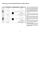
Close-up Photography
Exposure Compensation for Close-up Photography
When working very close to the subject, the exposure must be increased. The actual exposure factor will vary in accordance with the distance that the lens is extended. (Optical law: Light intensity decreases by
the square of the distance from the film plane).
Exposure compensation is easily determined by referring to the Exposure Compensation Scale.
After focusing the lens, read the exposure compensation factor on the
scale. The scale is divided into three zones of light, medium, and dark
shades. As indicated by the table at the base of the scale, the light zone
represents an exposure factor of zero (no compensation is necessary),
the medium shaded zone indicates +0.5 (a 1/2 stop increase in exposure
is required), while the dark zone denotes a factor of +1 (a full stop
increase in exposure is necessary).
To find the exposure factor, first locate the figure on the Focal Length
Scale for the lens in use. Next, move along the scale, in the same
column, until you reach the Distance Graduation. The shading of the
zone (light, medium, dark) which touches the Distance Graduation
indicates the correct exposure factor. For example, when the 110mm lens
is focused as shown in the illustration, the correct exposure factor is +1.
The scale curve for each lens has a white O mark which coincides with
the right-hand lens indication. So, use the mark to find the corresponding
scale curve for each lens.
With a factor of +0.5, open the aperture by a half-stop. For example,
assume that a hand-held exposure meter indicates a normal exposure
reading of f /16 at 1/60 sec., for an exposure compensation of +1, set the
lens to either f /16 at 1/30 sec. or f/11 at 1/60 sec.
When using a Mamiya through-the-lens (TTL) Exposure Meter Finder,
such as the RZ AE Prism Finder, it corrects automatically for close-up
photography.
• For optimum sharpness at the corners when using the 50 mm and
65mm wide-angle lenses at distances closer than 1 meter, use as small
an aperture as possible.
• The bellows extension in millimeters appears on the top of the Focal
Length Scale. These figures are used to determine the required
exposure compensation factor when using extension tubes.
• For areas covered with the bellows fully extended, see the instructions
for all interchangeable lenses.
35
Attaching a Lens with Shutter Released or Mirror Raised
When a lens is removed from the camera
body, the mirror is set (lowered) and the lens
shutter cocked. Conversely, when attaching
a lens, the same conditions should prevail
(mirror set and shutter cocked). However,
should a lens be attached with either the mirror raised or shutter released, or both, the
camera can be reset by following the procedures below.
1. If the mirror is raised (regardless of whether
the lens shutter is cocked or released), simply
depress the Cocking Lever to reset the
camera.
2. If mirror is set and lens shutter released
(closed), remove the Dark Slide from Film
Holder and depress the Shutter Release
Button (film will not be exposed). Next,
depress the Cocking Lever to reset the
camera.
3. When a lens is removed from the camera
both the mirror and the lens shutter are
cocked, or they can't be separated. Elsewhere we explained how to uncock both.
(For storage, for instance).
4. To rejoin them both have to be in a cocked
state. To cock the camera (lowering the
mirror), just activate the film advance lever,
To cock lens shutter, follow instructions
supplied with lenses.
36
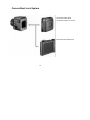
Camera Back Lock System
120 Roll Film Holder HA703
220 Roll Film Holder HB702
120 Roll Film Holder 6 x 4.5 HA704
Polaroid Pack Film Holder HP702
37
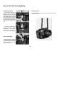
How to Use the Carrying Strap
Attaching the Strap
Carrying Position
Hold the metal clamp of the
strap so that the key-hole
shaped opening faces the Carrying Strap Lug on the camera
body. Gently fit the upper part of
the key-hole opening over the
lug. Next, gently push the bottom of the metal clamp upwards
and it will lock in place with a
click.
Since the Carrying Strap Lug is not rotary, the carrying strap will
not become twisted.
If the clamp is attached to the
Hot-Shoe side of the camera
upside-down, it will be difficult
to remove, so be careful to
attach the clamp right-side-up.
Removing the Strap
Reach behind the strap and
while gently squeezing the top
of the protruding front plate (leaf
spring), slide the clamp downward and off the lug.
38
Troubleshooting
Uniquely designed to prevent errors, the RZ67 incorporates numerous safety features, so if you can not release the
shutter, or remove a lens or holder, it is most likely due to
user error rather than a camera malfunction. Should
something appear to go wrong, be sure to check the
following points.
When the Film Holder can not be removed
Have you inserted the Dark Slide into the holder?
CAUTION:
When the shutter can not be released
1. Has the film been completely advanced to the first frame? Have
all the exposures already been made (10 with 120, 20 with 220)?
2. Has the Cocking Lever been advanced as far as it will go?
3. Has the Dark Slide been removed?
4. Have you locked the Shutter Release Button and forgotten?
5.Is there a battery in the Battery Chamber? Is the battery still good?
6. Is the "T" lever of the lens on "N"?
7. Is the camera speed dial on RBL and a RZ lens is on camera?
8.Is the camera speed dial on AEF and the AE Finder and a RZ lens
is not attached?
9. Have you used the mirror -up mode and red ring on the collar is
still visible after removing the cable release?
• In the case of examples 1-3, an orange lamp will illuminate in the
viewfinder if an error has been made.
When the lens can not be removed
Have you pressed the Cocking Lever completely forward?
39
• The winder RZ-1 cannot be used on the RZ PRO II body.
• When using the mirror-up operation in the B (bulb) mode, use
an optional double cable release.
• The previous models of AE Prism Finders or AE Magnifying
Finders cannot be used with the RZ PRO II unless their circuits
are modified. Contact your country's Mamiya Distributor for further
information.
• The AE Prism Finder FE701 can be directly mounted on the RZ
PRO II .
• Electronic Flash Precautions
Electronic Flash units that have a high sync trigger voltage may
seriously damage the electronic circuitry of your RZ PRO II. Flash
units with a maximum of 12 volts sync output trigger voltage are
safe for use. Please contact your flash manufacturer, or have your
local flash repair station test the sync line trigger voltage before
using with your RZ PRO II . Older studio flash power packs are
particularly suspect of using high voltage sync trigger voltages,
sometimes feeding as much as 400 volts into your RZ PRO II
sync terminal! To prevent this problem, your may consider using a
"filter" or regulating circuit between your power pack and sync
cord. Contact your local flash dealer or manufacturer for more
information about these devices.
Using RB Series Lenses and Accessories
Lenses
Finders
When using the RB series PD Prism Finder or PD Magnifying
Finder be sure the Electrical Contact Cover is in place, for it is used
to depress the switch at the base of the finder.
1. Focusing
RB67 lenses are mounted directly onto the RZ PRO II ; however,
the bellows must be extended 7 mm in order to focus the lens at
infinity. Therefore, even when photographing distant subjects, be
sure to use the Focusing Screen.
CAUTION: Because of the differences in flange back between the
two series of lenses, the Distance Scale of the RZ PRO II body
does not apply when using RB67 lenses.
CAUTION:
The RZ PD Prism Finder will not function on the RZ II . It cannot
be retrofitted.
2. Shutter Speed Selection
When a RB67 lens is mounted on the RZ PRO II body, use the
Shutter Speed Ring of the lens for shutter speed selection.
Be sure to set to the "RBL" position. Once this done all the other
speed dial settings are immobilized.
The shutter is cocked and released in the same manner as RZ
series lenses.
When using a Mamiya Sekor C lens for the RB series on the RZ
PRO II body, be sure to insert an optional interchange mounting
ring into the lens rear mount to assure correct coupling with the
camera body.
• Older RB Lenses should be checked before use, to determine if
their shutter torque is compatible with the RZ PRO II . Before try
ing, please send such lenses to the service department of your
country's Mamiya distributor.
40
Care of the Camera
Handling Camera
Proper Maintenance
As your camera is a precision instrument avoid exposing it to
severe vibrations or shock. Be careful when interchanging lenses
and film holders. Use the neckstrap whenever possible.
The Mamiya RZ PRO II is designed for heavy professional use
and will last indefinitely, if properly maintained. Every camera has
mechanisms like film transport, shutter, diaphragm blade etc.
They are controlled by gears. levers, springs, rollers, etc., which are
subject to wear and tear and also require special lubrication from
time to time. Ambient conditions like dust. sea air and moisture can
also affect these mechanisms.
To uncock the mirror and the lens shutter, remove the lens from
the cocked camera. Press the release button and the mirror will go
up and stay up. To release shutter of cocked lens, see instructions
on page 13.
We recommend that the camera body should be serviced at least
about every 50,000 exposures (about 5000 rolls of 120 film): your roll
film holders about every 20,000 exposures; your leaf shutter lenses
about every 10, 000 exposures.
Storage
When not used for a long period of time remove the battery and
film from the camera and keep mirror and shutters in uncocked
state. Avoid storing the camera and lenses in humid or sea air
atmosphere or in extreme hot or cold environment. Periodically
exercise film transport and shutters by making a number of blind
exposures at various shutter speeds and f/stops.
Cleaning
Never touch the lens or mirror surfaces. If a lens needs cleaning,
use a blower or lens tissue to remove dust particles. Never use
anything other than a blower for the mirror, as its surface should
never be touched.
Please contact the Mamiya Distributor in your country for service
information.
Periodic Examination
Periodically check the camera to make sure it is in working order.
This is especially important before beginning a photographic
session or assignment. Check the battery, flash synchronization,
mirror and shutter operation, diaphragm automation, and film
advance. Also check any accessories you plan to use.
• Features and specifications subject to change without notice.
41