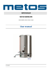
1
PRIMEA LINE
2007
TECHNICAL SERVICE
MANUAL
All parts of this document are property of Saeco International Group. All rights reserved.
This document and relative information herein is provided without liability deriving from any errors or omissions. Furthermore,
no part may be reproduced, used or collected with the exception of that authorized in writing or in accordance with a contractual clause.
Issue March 2007
REV. 00 - Mar. 07
PRIMEA TECHNICAL SERVICE MANUAL (rev.00 March 07)
1.
1.1
1.2
1.3
Introduction (rev.00)
Documentation required
Tools and equipment required
Safety warnings
2.
2.1
2.2
Technical data (rev.00)
Product technical data
Internal / external machine components
3.
3.1
3.2
Summarized instructions (rev.00)
Client and programming menu (rev.00)
Maintenance and cleaning (rev.00)
4.
4.1
4.2
4.3
Diagrams (rev.00)
Wiring diagram (rev.00)
Component load table (rev.00)
Water circuit diagram (rev.00)
5.
5.1
5.2
5.3
5.4
5.5
5.6
Troubleshooting (rev.00)
Primea Touch and Touch Plus test functions (rev.00)
Primea Touch e Touch Plus diagnosis function (rev.00)
Primea Ring test functions (rev.00)
Primea Ring diagnosis function (rev.00)
Error messages for Service personnel (rev.00)
Problems, Causes, Remedies (rev.00)
6.
6.1
6.2
6.3
6.4
6.5
Operating logic (rev.00)
Multi-way valve (rev.00)
Autocappuccino assembly (rev.00)
Motor-driven tray (rev.00)
Prima water (rev.00)
SBS valve (rev.00)
7.
7.1
7.2
7.3
7.4
7.5
7.6
7.7
7.8
7.9
7.10
7.11
7.12
7.13
7.14
7.15
7.16
Component assembly / disassembly (rev.00)
Top cover (rev.00)
Right side cover (rev.00)
Left side cover (rev.00)
Coffee dispensing head (rev.00)
Electronics (rev.00)
Gearmotor (rev.00)
Pump (rev.00)
Boiler and multi-way valve assembly (rev.00)
Boiler (rev.00)
Multi-way valve (rev.00)
Oetiker clamp assembly and disassembly (rev.00)
Grinder (rev.00)
Grinder adjustment/assembly and disassembly
Strength adjustment (rev.00)
Autocappuccino facility (rev.00)
Motor-driven drip tray (rev.00)
8.
8.1
Maintenance schedule (rev.00)
Routine maintenance Check list (rev.00)
9.
9.1
Amendments made to technical service manual (rev.00)
Latest amendments (rev.00)
PRIMEA 2007 Contents
1/1
REV. 00 - Mar. 07
CHAPTER 1
INTRODUCTION
REV.00
PRIMEA 2007 Chapter 01
REV. 00 - Mar. 07
1.1
Documentation required
The following technical documentation l is required for repairs:
Instruction booklet for specific model
Technical documentation for specific model (diagrams, exploded drawings)
1.2
Tools and equipment required
As well as the standard equipment, the tools listed below are required.
1 Special screwdriver with Torx T15 tip and Pozi Drive screwdriver for casing and work
on the grinder.
1 digital thermometer with full 200°C scale
This must be suitable for measuring in liquids and on surfaces.
1 set of pliers for Oetiker clamps
1 pincer
1.3
Safety warning
Before starting operations on the machine, consult the instruction booklet.
Observe all current standards related to the repair of domestic appliances.
Always disconnect the power plug from the mains before carrying out repairs. Simply turning
off the main switch is not sufficient to prevent electrical discharge.
This domestic appliance is rated as insulation class I.
Insulation and dielectric rigidity tests must be performed on completion of repairs.
PRIMEA 2007 Chapter 01
1/1
REV. 00 - Mar. 07
CHAPTER 2
TECHNICAL DATA
REV.00
PRIMEA 2007 Chapter 02
REV. 00 - Mar. 07
2.1
Product and component technical data
Power supply and output:
Temperature control:
Safety system:
Coffee heat exchanger output:
Stainless steel
230V~, 50 Hz, 1500 W / 120V~,50/60 Hz, 1300W
2 (NTC) variable resistor sensors – transmit the value to
the electronic board
Thermostat at 190°C with manual reset on
both boilers + 192° fuse
1300 W - to dispense coffee and hot water
Steam heat exchanger output
Stainless steel
1090 W – for steam delivery
Motor-driven tray
Water levelsensor
Gearmotor:
24V stepper motor
Capacitive sensor
DC motor (24 V) in two directions
of rotation
Activated via MENU display
PTC Type
Ulka reciprocating piston type with thermal cutout at
100°C
48 W, 230V, 50 Hz, Type EP5 GW
41 W, 120V, 50 Hz
approx. 13 - 15 bars
Opening at approx. 17 - 19 bars
In tank
DC motor with ceramic plate
grinders
Hall sensor – Pulse control. Dose adjustment can
be set from 7 – 10g.
Beverage selection control
Enables automatic frothing
During heating phase
approx. 5.6A to 230V / 10.8A to 120V
On Stand –By approx. 4.6 Wh in machine ready status no
beverages dispenses 39Wh 4.5A (230V)
350/390/430
14 kg
1.75 l / 0.46 Gal
350 g. coffee beans
0.32 l / 10.8 oz
approx. 10 cc / 0.34 oz
approx. 10 sec on first filling cycle
approx. 55 sec.
approx. 73°C - 83°C
approx. 6-8 sec.
Cup warmer plate:
Pump:
Pressure relief valve:
Water filter:
Grinder:
Coffee strength control
Multi-function valve
Cappuccino valve
Amps:
Energy consumption:
Dimensions: l x h x d in mm:
Weight:
Water tank holds:
Coffee container capacity
Milkcontainer capacity
Heat exchanger capacity:
Water circuit filling time:
Heating time:
Dispensed drink temperature:
Grinding time:
PRIMEA 2007 Chapter 02
1/3
REV. 00 - Mar. 07
2.2
Internal / external machine components
External:
Coffee bean
hopper lid
Coffee bean
coffee beans
Pre-ground
coffee shoot
Cup
warmer
Touchscreen
display
Main on/off
switch
SBS
Service
door
Dispensing
head
Grounds drawer
Drip
tray
Touch sensor to raise/lower
drip tray
Milk tank compartment
Hot water dispense
pipe (spout)
Water tank
Dispensing head
Drip tray
PRIMEA 2007 Chapter 02
2/3
REV. 00 - Mar. 07
Internal:
Brew drive assembly
compartment
Boiler valve
assembly
Multi-way valve
Cappuccino
valve assembly
Cappuccino valve
assembly
Grinder
Power board
Door
microswitch
PRIMEA 2007 Chapter 02
3/3
REV. 00 - Mar. 07
CHAPTER 3
BRIEF
INSTRUCTIONS
REV.00
PRIMEA 2007 Chapter 03
REV. 00 - Mar. 07
3.1
Client and programming menu
Client menu: To access, press “Programming menu”
The programming menu will open:
Machine function
programming
Special functions
Maintenance
(appliance cleaning)
Machine
settings
Specials
Beverage
settings
Main
menu
Maintenance
Additional
functions
Set clock
Coffee
preparation
menu
Standby
Set appliance to
standby
Detailed beverage
programming
Extra functions
- Current date and time
- Standby timer
- Set on/off times
during the day
Go back to main menu
Submenu
Machine settings: Modify main machine parameters
Cup illumination on/off
Set menu
language
Set display colour
brightness
Set/enable buzzers
Water
filter
Set machine operation for
use with a “Prima water”
filter
Language
Cup
illumination
Display
Machine
settings
Water
hardness
tones and
buzzer
warnings
Cup warmer
function
Rinse
Set circuit rinsing
Go back
to menu
To set cup warmer function
Go back
Restore
default
settings
Set water
hardness
PRIMEA 2007 Chapter 03
1/5
REV. 00 - Mar. 07
Special function: Reset factory settings
Reset factory
settings
Factory
settings
Specials
Go back
Go back to
menu
Maintenance: Maintenance and appliance cleaning
From this menu you can:
Lock the
touchscreen
Coffee
circuit
cleaning
Display
lock
Start the dispensing
head cleaning cycle
Maintenance
Start milk circuit
cleaning cycle
Milk circuit
cleaning cycle
Descaling
Run descaling
cycle
Go back to
menu
Go back
Beverage settings: Programming individual beverages
Hot
temperature
Espresso
macchiato
Espresso
Caffè
Beverage
settings
Caffè
lungo
Go
back
latte
macchiato
Cappuccino
Coffee settings
Normal prebrewing
Go
back
Ground coffee
strength
Medium
Restore
default
settings
The temperature
of the dispensed
coffee
Amount of
coffee to grind
Go back to
menu
Go back
to menu
PRIMEA 2007 Chapter 03
2/5
REV. 00 - Mar. 07
Additional functions:
Coffee type selection
Demo
Caffè
in the
world
Presentation of
appliance
Additional
functions
Total beverages
dispensed
Beverage
counters
Go back
Restore
default
settings
Save
settings
Go back
to menu
Timer settings:
Set clock
Set date and display
format
Clock settings
To set stand-by
parameters after
coffee has been
dispensed
Stand-by
settings
Go back
Clock
settings
Set current
time
Go back to
menu
PRIMEA 2007 Chapter 03
3/5
REV. 00 - Mar. 07
3.2
Maintenance and cleaning
STEPS
A
B
C
D
E
F
Empty coffee grounds drawer
Empty drip tray
Clean water tank
Clean the coffee bean hopper
Clean casing
Clean and grease the dispensing head
G
H
I
J
K
Clean brew group filters
Descaling
Clean milk circuit
Clean drip tray
Clean coffee circuit
As instructed
As necessary
Weekly
As necessary
As necessary
Once a month or every
500 coffees dispensed
Once a month
As instructed
After each time milk dispensed
Weekly
Weekly
Descaling for Primea Duo - Touch Plus and Touch
Hardness
Water hardness
1
Soft water
(up to 7ºdH)
2
Medium water
(7º-14ºdH)
3
Hard water
(15º-21ºdH)
4
Very hard water (over 21ºdH)
Descaling
Descaling
frequency
Approx. every 3
months/120 l (31.6 Gal)
Approx. every 2 months
/ 90 l (23.75 Gal)
Approx. every 6 weeks/
60 l (15.8 Gal)
Approx. every 4 weeks/
30 l (7.9 Gal)
Descaling frequency
when usingAqua Prima
Approx. every 3 months/
150 l (39.5 Gal)
Approx. every 2 months/
120 l (31.6 Gal)
Approx. every 6 weeks/
90 l (23.75 Gal)
Approx. every 4 weeks/
60 l (15.8 Gal)
DESCALING
Descaling
frequency
Approx. every 3
months/120 l (31.6 Gal)
Approx. every 2 months/
90 l (23.75 Gal)
Approx. every 6 weeks/
60 l (15.8 Gal)
Approx. every 4 weeks/
30 l (7.9 Gal)
Descaling frequency
when usingAqua Prima
Approx. every 3 months/
240 l (63.2 Gal)
Approx. every 2 months/
180 l (47.4 Gal)
Approx. every 6 weeks/
120 l (31.6 Gal)
Approx. every 4 weeks/
60 l (15.8 Gal)
Descaling for Primea Ring
Hardness
1
Water hardness
Soft water
(up to 7ºdH)
2
Medium water
(7º-14ºdH)
3
Hard water
(15º-21ºdH)
4
Very hard water (over 21ºdH)
PRIMEA 2007 Chapter 03
4/5
REV. 00 - Mar. 07
REV. 00 - Mar. 07
All models
Primea
Cappuccino
Ring
Primea
Cappuccino
Touch
Press key or select from menu
The appliance counts down remaining beverages
every 60 seconds for approx. 5 seconds.
From V. SW. 01.00.07: If it is not
cleaned within 21 days, all beverages
will be blocked.
From when the descaling message
appears, the appliance counts down on
the display from 200 coffees, then at
the last 30, the message flashes on the
screen (200 beverages of any type and
size in ml are counted).
If it is not cleaned within 14 days, all beverages will be blocked,
From when the descaling message appears, the appliance counts down on the
display from 100 coffees. Then for the last 30, the message flashes on the
screen (100 beverages of any type and size in ml are counted).
When ready, the coffee circuit is rinsed.
Runs only when selected
After 24 coffees, the appliance requests that grounds are removed.
60 litres or 90 days from the first use or after it has been unused for 20 days.
frequency
Coffee circuit
rinse
Clean coffee
circuit
Empty coffee
grounds
Aqua Prima
Approx. 25
Min
Approx. 5
Sec
Approx. 60
Sec
Resets when drawer is extracted for 5 seconds with
the appliance switched on.
When enabled from the menu, approx. 500ml of
water is released.
Approx. 30
Sec
Approx. 45
Min
Approx. 25
Min
Approx. 25
Min
Approx. 30
Sec
Approx. 30
Sec
Approx. 45
Min
No
During diagnosis
During diagnosis
This function can be disabled
from the menu.
During diagnosis, you can
vary notification and block
times, and during testing you
can reset Lev. B
No
During diagnosis, you can
vary notification and block
times, and during testing you
can reset Lev.. B mode.
During diagnosis, you can
vary notification and block
times, and during testing you
can reset Lev. B
No
During diagnosis
During diagnosis
During diagnosis
No
Approx. 25
Min
Approx. 25
Min
No
Approx. 30
Sec
During diagnosis
During diagnosis
During diagnosis
No
No
Possibility to stop/
change
Approx. 30
Sec
Approx. 45
Min
Approx. 30
Sec
Approx. 10
Min
Approx. 10
Min
Approx. 30
Sec
Duration
The unit rises and releases approx. 600 ml of water
in spurts.
The unit rises and releases approx. 50ml of water.
Press key or select from menu
Press key or select from menu
After 20 minutes If it is not rinsed, milk-based beverages can no longer be selected.
From V. SW. 01.00.07: After 14 days,
the appliance requests that is cleaned
with with a cleaning tablet or powder.
Press key or select from menu
The countdown for the whole 200
coffees is shown on the display.
Press key or select from menu
Press key or select from menu
Press key or select from menu
Press key or select from menu
The appliance requests that the milk circuit is pulse-rinsed right away; beverages can
still be selected.
From when the descaling message appears, the appliance counts down internally
from 200 coffees. After 100, the countdown appears on the display then for
the last 30 coffees, the message flashes on the screen (200 beverages of any
type and size in ml are counted).
This refers to milk-based beverages only.
The countdown for the whole 200
coffees is shown on the display.
Press key or select from menu
After 7 days, the appliance requests that is cleaned with with a cleaning tablet/
powder.
Milk
frequency
After 14 days, the appliance requests that is cleaned with with a cleaning tablet or
powder.
If it is not cleaned within 21 days, all beverages will be blocked.
After 20 minutes If department is not rinsed, beverages can no longer be selected.
The appliance requests that the milk circuit is pulse-rinsed right away; beverages can
still be selected.
Milk
If it is not cleaned within 21 days, all beverages will be blocked.
Press key or select from menu
Press key or select from menu
After 14 days, the appliance requests that is cleaned with with a cleaning tablet
or powder.
After 20 minutes If department is not rinsed, beverages can no longer be selected.
Mode
Press key or select from menu
This refers tomilk-based beverages only.
Possible variations
The appliance requests that the milk circuit is pulse-rinsed right away; beverages can
still be selected.
frequency
Milk
Primea
Cappuccino
Touch Plus
Screen messages
From when the descaling message appears, the appliance counts down internally
from 200 coffees. After 100 coffees, the countdown appears on the display,
then for the last 30 coffees, it flashes (200 beverages of any type and size in ml
are counted).
Function
Model
Maintenance messages
PRIMEA Chapter 03
5/5
CHAPTER 4
DIAGRAMS
REV.00
PRIMEA 2007 Chapter 04
REV. 00 - Mar. 07
REV. 00 - Mar. 07
4.1
Wiring diagram
Primea Touch Plus
PRIMEA 2007 Chapter 04
1/6
REV. 00 - Mar. 07
Primea Touch
PRIMEA Chapter 04
2/6
REV. 00 - Mar. 07
Primea Ring
PRIMEA Chapter 04
3/6
4.2
Component load table
Component
Connector
Mains voltage/Mains switch
Autocappuccino valve drive
Milk tank presence microswitch
JP 46
JP 30
JP 31
Cappuccino valve presence microswitch
Drip tray motor
Pin
number
1/3
Resistance/Voltage
3/4
230 V AC / 120V AC
304 Ohm 24 V AC
3.3 V DC
JP 31
1/2
3.3 V DC
Upper multi-valve microswitches
Lower multi-valve microswitches
Cup warmer
Steam boiler sensor
Coffee boiler sensor
Unit door microswitch
Unit presence microswitch
Gearmotor microswitches (up unit)
Gearmotor microswitches (unit down)
Dreg drawer microswitch
Drip tray microswitch
Drip tray full capacitive sensor
Gearmotor
Full tank capacitive sensor
Coffee container cover microswitch
Coffee boiler 1300W
Cup illumination ON led
Motor-driven tray capacitive key activated
Motor-driven tray capacitive key not activated
JP
JP
JP
JP
JP
JP
JP
JP
JP
JP
JP
JP
JP
JP
JP
JP
JP
JP
JP
JP
JP
JP
JP
JP
JP
JP
1/2
3/4
7/8
5/6
4/5
5/6
7/8
9/10
11/12
1/3
3/4
1/2
Grinder
JP 42
90 Ohm 24V AC
91 Ohm 24V AC
3.3 V DC
3.3 V DC
230V AC
90 Ohm 24V AC
90 Ohm 24V AC
3.25 V DC
3.25 V DC
Approx. 560 Ohm 230 / 120 V AC
3.5 Kilo Ohm x 25°C
3.5 Kilo Ohm x 25°C
24 V DC
3.3 V DC
3.3 V DC
3.3 V DC
24 V DC
3.25 V DC
3.3 V DC
22 Ohm
3.3 V DC
3.25 V DC
39 Ohm 230 V AC
2,0 V DC
4.5 V DC
4.5 V
64 Ohm AC 250 V DC
120V DC
Approx. 200 mA - Ac 420 mA
230V AC 400-450 mA
120V AC 950/1050 mA
Upper drip tray microswitch
Lower drip tray microswitch
Ulka pump
Multi-valve motor
33
33
33
33
42
32
32
32
32
42
32
32
40
35
35
35
35
36
36
35
37
41
45
39
34
34
5/6
3/4
1/2
7/8
4/5
1/2
9/10
6
1/2
3
2/3
4/3
6/7
Grinder absorption - coffee container empty
Grinder absorption - Coffee container full
Fuse F1 T8A - 250V AC To protect the grinder, coffee boiler, cup warmer and pump.
Fuse F1 T15A - 125V AC
Fuse F3 T2A
To protect the mains electricity power card
PRIMEA 2007 Chapter 04
4/6
REV. 00 - Mar. 07
""
!
)4,/-1)(4-/-'2156&)
8
'2()
)4,/-1)(4-/-'2156&)
8
'2()
#
)4,/-1)(4-/-'2156&)
8
'2()
# !
)4,/-1)(4-/-'2156&)
8
'2()
)4,/-1)(4-/-'2156&)
8
'2()
)4,/-1)(4-/-'2156&)
8
'2()
)4,/-1)(4-/-'2156&)
8
'2()
""
'2()
-/-'2156&)
8
'2()
)4,/-1)(4-/-'2156&)
8
'2()
! #$
""
!
-/-'2156&)
8
'2()
)4,/-1)(4-/-'2156&)
8
'2()
))56&)*23
0-/.()/-7)39
'2()
-/-'2156&)
8
'2()
-+0)4%563&-1)
'2()"
$
REV. 00 - Mar. 07
! !
""
# '2()
-/-'2156&)
8
'2()
)4,/-1)(4-/-'2156&)
8
'2()
#!
4.3
Water circuit
Primea Touch Plus
$
PRIMEA 2007 Chapter 04
5/6
REV. 00 - Mar. 07
$
%3*2407/6-9%;
8%/8)
'2()
""
#
157/%6-21'28)4-1+
*24,)%6)4
'2()
# !
)5,/-1)(5-/-'2167&)
:
'2()
""
! !
)5,/-1)(5-/-'2167&)
:
'2()
)5,/-1)(5-/-'2167&)
:
'2()
)5,/-1)(5-/-'2167&)
:
'2()
)5,/-1)(5-/-'2167&)
:
'2()
)5,/-1)(5-/-'2167&)
:
'2()
)5,/-1)(5-/-'2167&)
:
'2()
""
'2()
)5,/-1)(5-/-'2167&)
:
'2()
! #$
""
)5,/-1)(5-/-'2167&)
:
'2()
!
!
-/-'2167&)
:
'2()
-/-'2167&)
:
'2()
-+0)5%674&-1)
'2()"
273/-1+*24
9%6)4(4%-1
'2()
))67&)*24
0-/.()/-8)4;
'2()
$
-/-'2167&)
:,
'2()
# '2()
-55-3%6)4*24
,)%6)4
'2()
)5,/-1)(5-/-'2167&)
:
'2()
#!
Primea Touch /Ring
PRIMEA Chapter 04
6/6
CHAPTER 5
TROUBLESHOOTING
REV.00
PRIMEA 2007 Chapter 05
REV. 00 - Mar. 07
5.1
Primea Touch Plus and Touch test functions
The functions of the second water boiler do not apply to the Touch model.
2
3
4
1
During the first 3 seconds after start-up of the appliance (or on exit from standby
mode) the user can access test mode by pressing the keys in the sequence
shown alongside.
In test mode, the machine functions can be checked, and are divided into four
macro-groups.
CPU print software version:
V_00.00.00
power print software version:
V_00.00.00
The display shows:
CPU print boot loader version:
V_00.00.00
brew unit
grinder
ESC
Multi valve
Cup lift
Capp.valve Illumination
Pump
heaters
Brew group
Grinder
-
CPU card software version
Power card software version
Description of functions
Esc key to exit Test Mode
Version of boot loader on CPU
Software
Version
ESC
Multi valve
Cup lift
Capp.valve Illumination
Pump
heaters
Software
Version
ESC
Shows software version
FUNCTION GROUP 1:
- Brew group (upwards/downwards)
- Grinder (function)
FUNCTION GROUP 3:
- Motor-driven tray (upwards/downwards)
- Cup illumination (ON/OFF)
- Cup warmer
- Boilers (ON/OFF)
FUNCTION GROUP 2:
- Multi-way valve (positioning)
- Cappuccino valve (positioning)
- Pump (ON/OFF)
PRIMEA 2007 Chapter 05
1/20
REV. 00 - Mar. 07
5.1.1 Function group 1 - brew group, grinder, boiler power supply.
Brewunit
Errors
inserted
Dregdraw:OK
Door:OK
DripWater:OK
Tray miss:OK
brew unit
home
grinder
go
Impulses
Med. Aroma
75
brew unit
grinder
brew unit
work
Grinder A
Imp:000
Top open
multi valve
cup lift
capp.valve illumination
pump
heaters
software
version
ESC
Dispensing head home: brew group in home position
Is home - rest position (Gearmotor micro.)
Brew group work:
brew group in brewing position.
Is work - delivery position (gearmotor micro)
Brew group:
inserted - unit inserted (unit micro)
Missing - unit missing (unit micro)
Grinder go:
grinder running.
Grinder:
Imp:000 - grinder pulses.
Top open - coffee container cover open.
Top closed- coffee container. cover closed.
Impulses
Grinder pulse control (min.60 - max. 200) in
steps of 05
Med. aroma
sets quantity of ground coffee
Function group 2 - multi-way valve, cappuccino maker valve, pump
multi
valve
left
capp.valve
next
position
solenoid
Multival:OK
Pos3:Init
Ms: Top
Ms: Bot
Cupp.Valve
reached
Pos1:Init
Flowmeter
Imp.:000
Hz:000
Errors
Dregdraw:OK
Door:OK
WaTank:OK
WaLevel:OK
DripWater:OK
MilkTank:OK
MilkDraw:OK
Tray miss:OK
multi
valve
right
pump
Sensor
St:124:OK
Wa:100:OK
brew unit
grinder
multi valve
cup lift
capp.valve illumination
pump
heaters
software
version
ESC
Multi valve left:
Multi valve right:
Multival:OK
Pos1:Steam
Pos2:St.Pre.
Pos3:Init
Pos4:Coffee
Pos5:Hotwa.
Pos6:Rinsing.
Cupp.valve next:
position
Pos1:Init
Pos2:Foam
Pos3:Milk
pump:
Turbo:OK
Imp.:000
Hz:
Solenoid:
Multi-way valve turns left
multi-way valve turns right
multi-way valve OK or faulty (ER)
Steam setting (hot milk and froth)
Steam pressure
before delivery of milk or froth
Reset position - initialisation
Coffee brew setting
Hot water dispense setting
Milk circuit autorinse position
Cappuccino valve command
Reset position - initialisation
Milk frothing setting
Hot milk dispense setting
Pump
Pump OK or faulty (ER)
Turbine pulses (40 - 60 OK)
000
Activation of electromagnet that closes the
milk door
Function group 3 - drip tray, cup illumination, cup warmer, boiler supply
cuplift
up
cuplift
down
Cuplift
Errors
Dregdraw:OK water heater
(1300W)
Door:OK
Is bottom
Key up:Off
WaTank:OK
Key down:Off WaLevel:OK
DripWater:OK
MilkTank:OK
MilkDraw:OK
Tray miss:OK
Sensor
illumination St:103:OK
steam
heater
(1100W)
cup
heater
Wa:97:OK
brew unit
grinder
multi valve
cup lift
capp.valve illumination
pump
heaters
software
version
ESC
Cuplift up:
Cuplift down:
Cuplift:
Is bottom:
Is Top
Key up: OFF
Key down: OFF
Illumination:
Cup warmer
Steam boiler:
Water boiler:
Sensor:*
Tray up movement
Tray downwards movement
Tray downwards (lower micro)
tray up (upper micro)
ON/OFF-Up key pressed
ON/OFF-Down key pressed
cup illumination (press and hold)
cup warmer plate (press and hold)
1100W - powers steam boiler.
1300W - powers water boiler.
Max 150
Key: In black: Keys
In blue: Check status
* See next page (sensors)
PRIMEA 2007 Chapter 05
2/20
REV. 00 - Mar. 07
5.1.2 Microswitch and sensor check
Errors
(Errors)
Grounds drawer:
(Dregdraw:)
Grounds drawer micro
OK Drawer present
ER drawer missing
Service:
(Door:)
Door microswitch
OK door closed
ER door open
Water tank:
(WaTank:)
Tank Micro
OK tank engaged
ER tank empty or in reserve (see diagnostics)
Water level:
(WaLevel)
Water level capacitive sensor
OK Water present
ER Water low
Drip. tray:
(DripWater:)
Drip tray capacitive sensor
OK drip tray empty
ER drip tray full
milk tank:
(MilkTank)
Milk tank door micro
OK milk tank door closed
ER milk tank door open
Cappuccino valve:
(Milk Draw:)
Milk tank + cappuccino valve micro
OK milk tank and cappuccino valve inserted
ER milk tank and/or cappuccino valve not found
Drip. tray:
(no drip tray)
(Tray miss:)
Drip tray micro
OK tray present
ER no tray
Sensors
St: steam
Steam boiler temperature sensor (Touch Plus only)
Number: current temperature
OK Sensor connection ok
ER sensor shorted or disconnected
Wa: water
Water boiler temperature sensor
Number: current temperature
OK Sensor connection ok
ER sensor shorted or disconnected
Errors
Dregdraw:OK
Door:OK
WaTank:OK
WaLevel:OK
DripWater:OK
MilkTank:OK
Milk Draw:OK
Tray miss:OK
Sensor
St:100:OK
Wa:100:OK
PRIMEA 2007 Chapter 05
3/20
REV. 00 - Mar. 07
5.2
Touch Plus and Touch diagnosis function
The functions of the second water boiler do not apply to the Touch model.
Procedure for access to diagnostics mode.
Turn the appliance off and then on again or exit standby mode to enter the diagnostics menu, according to
the sequence shown in the figure.
When accessing the diagnostics menu, there is a timeout limit of 3 seconds between one selection and the
next (1,2,3,4).
Beveragecounters
Total
counters
Beverage
settings
System settings
Diagnostics Water circuit
menu
Error
counters
emptying
auto test
Exit diagnostics
menu
1
2
3
4
A window is displayed showing the following options:
• Beverage counters
• Total counters
• Error counters
• Beverage settings
• System settings
• Steamout (circuit emptying)
• Auto test
• Exit diagnostics menu
Description of options available
5.2.1 Beverage counters
Total hot milk beverages
• Total beverages
• Beverage dispense time (sec.)
Total latte macchiato beverages
• Total beverages
• Water used (ml.)
Total cappuccino beverages
• Total beverages
• Water used (ml.)
Total espresso macchiato beverages
• Total beverages
• Water used (ml.)
Total hot water beverages
• Total beverages
v Water used (ml.)
Total caffelungo beverages
v Total beverages
v Water used (ml.)
Total coffee beverages
v Total beverages
v Water used (ml.)
Total espresso beverages
v Total beverages
v Water used (ml.)
not modifiable
not modifiable
not modifiable
not modifiable
not modifiable
not modifiable
not modifiable
not modifiable
not modifiable
not modifiable
not modifiable
not modifiable
not modifiable
not modifiable
not modifiable
not modifiable
PRIMEA Chapter 05
4/20
REV. 00 - Mar. 07
Total pre-ground coffee beverages
v Total beverages
v Water used (ml.)
Total all beverages
v Total beverages
not modifiable
not modifiable
not modifiable
5.2.2 Total counters
Water used since production (ml.)
Water used since last descaling (ml.)
Water used since last descaling message (ml.)
Water used since last descaling (ml.)
v Water used counter (last) 0 ml.
v Water used counter (second last) 1 ml.
v Water used (third to last) 2 ml.
Total descaler used
Water used by filter since last reset (ml.)
Water used with water filter enabled since production (ml)
Number of descalings (cycles)
Number of dispensing head cleaning cycles
Number of milk circuit rinse cycles
Number of cappuccino valve cleaning cycles
Water filters used since production (cycles)
Number of dispensing head removals (cycles)
Beverages up to descaling (cycles)
Machine active time (sec.)
Temporary descaling counter
Water circuit emptying counter (cycles)
not modifiable
modifiable
not modifiable
not modifiable
not modifiable
not modifiable
modifiable
not modifiable
not modifiable
not modifiable
not modifiable
not modifiable
not modifiable
not modifiable
modifiable
not modifiable
not modifiable
not modifiable
5.2.3 Error counters (access submenu)
The machine records the followingerrors (see also section 5.3)
01)
02)
03)
04)
05)
07)
08)
09)
10)
11)
12)
13)
14)
15)
16)
17)
18)
19)
20)
Grinder 1 blocked
Grinder 2 blocked
Dispensing head blocked; up command
Dispensing head blocked; down
Pump flow rate error (fill circuit)
Multivalve blocked
Capp. valve. blocked
Powercomm error (communication error with power card)
Water boiler sensor disconnected
Water boiler sensor short circuited
Steam boiler sensor disconnected
Steam boiler sensor short circuit
Water boiler disconnected
Steam boiler disconnected
Both dispensing head microswitches active
EEPROM read and write error
Real time clock oscillator stopped
No zero crossing in mains supply
Cuplift both microswitches active
All these errors display the following submenu
v Production errors
v Errors since last service
v Current
not modifiable
resettable – modifiable
resettable – modifiable
Ringbuffer errors: the last 20 errors are saved.
v
Error 1/20,2/20,3/20,4/20,5/20,6/20,7/20,8/20,9/20,10/20,11/20,12/20,13/20,14/20,15/20,
16/20,17/20,18/20,19/20,20.
PRIMEA Chapter 05
5/20
REV. 00 - Mar. 07
5.2.4 Ring buffer repair code
Buffer history repair
This area records interventions of the Service Centres (up to a maximum of 10).
The Service Centre enters the fault codes via PC as transmitted by Saeco I.G. (e.g: CLD01)
1.
1.
1.
1.
1.
group errors
code errors
day errors
month errors
year errors
2.................
10.
10.
10.
10.
10.
group errors
code errors
day errors
month errors
year errors
Machine status (all modifiable)
•
•
•
•
•
•
•
•
•
•
•
•
•
•
•
•
•
•
•
•
1
2
4
8
16
32
64
128
256
512
1024
2048
4096
16384
32768
65536
131072
Prime circuit (yes/no)
Water filter (not inserted/inserted)
Unit full (yes/no)
Display add coffee grinder 1 (yes/no)
Display add coffee coffee grinder 2 (yes/no)
Time format (am/pm)
Standby (yes/no)
Rinse (enable/disable)
Cup illumination (enable/disable)
Grinder 1 out of coffee (warning message management) sec.
Grinder 2 out of coffee (warning message management sec.
Milk circuit rinse required (yes/no)
Demo mode (disable/enable) command
Display icons (yes/no)
Warning tone ready (enable/disable)
Milk quality warning (enable/disable)
Key press tone (enable/disable)
Water filter activation suspended (yes/no)
Language selection on power-on (yes/no)
Milk circuit rinse
PRIMEA Chapter 05
6/20
REV. 00 - Mar. 07
5.2.5 Beverage settings
SYSTEM SETTINGS
parameters
HOT MILK
Beverage data modified
Milk time
Froth time
LATTE MACCHIATO
Beverage data modified
Temperature
Aroma
Grinding ratio
Pre-brewing
Water
Milk time
Froth time
CAPPUCCINO
Beverage data modified
Temperature
Aroma
Grinding ratio
Pre-brewing
Water
Milk time
Froth time
ESPRESSO MACCHIATO
Beverage data modified
Temperature
Aroma
Grinding ratio
Pre-brewing
Water
Milk time
Froth time
HOT WATER
Beverage data modified
Water
CAFFE’ LUNGO
Beverage data modified
Temperature
Aroma
Grinding ratio
Pre-brewing
Water
COFFEE’
Beverage data modified
Temperature
Unit of
measurement
by user
yes/no
0 ... 40
0 ... 40
No
0
25
yes /no
low, high, medium
medium, light, preground, strong
0 ... 100
disabled, strong, normal
50 ... 450
0 ... 40
0 ... 40
No
medium
medium
100
normal
135
0
27
yes /no
low, high, medium
medium, light, preground, strong
0 ... 100
disabled, strong, normal
50 ... 450
0 ... 40
0 ... 40
No
medium
medium
100
normal
135
0
22
turb. pulses.
seconds
seconds
yes /no
low, high, medium
medium, light, preground, strong
0 ... 100
disabled, strong, normal
50 ... 450
0 ... 40
0 ... 40
No
medium
medium
100
normal
135
0
5
turb. pulses.
yes /no
50 ... 450
No
210
yes /no
low, high, medium
medium, light, preground, strong
0 ... 100
disabled, strong, normal
50 ... 450
No
medium
medium
100
normal
440
yes /no
low, high, medium
No
medium
seconds
seconds
by user
percentage
turb. pulses.
seconds
seconds
by user
percentage
turb. pulses.
seconds
seconds
by user
percentage
by user
by user
percentage
turb. pulses.
by user
Default
value
Settings range
PRIMEA Chapter 05
7/20
REV. 00 - Mar. 07
Aroma
Grinding ratio
Pre-brewing
Water
ESPRESSO
Beverage data modified by user
Temperature
Aroma
Grinding ratio
Pre-brewing
Water
EXTRA MILK
Time
percentage
turb. pulses.
percentage
turb. pulses.
seconds
medium, light, preground, strong
0 ... 100
disabled, strong, normal
50 ... 450
medium
100
normal
280
yes /no
low, high, medium
medium, light, preground, strong
0 ... 100
disabled, strong, normal
50 ... 450
No
high
medium
100
normal
165
0 ... 40
5
PRIMEA Chapter 05
8/20
REV. 00 - Mar. 07
5.2.6 System settings
SYSTEM SETTINGS
parameters
Unit of
measurement
Settings range
Default value
SETTING
Water boiler temperature enabled
Water boiler temperature disabled
Steam boiler temperature enabled
Steam boiler temperature disabled
Average temperature in cup
Last use of dispensing head
Last use of dispensing head
°C
°C
°C
°C
°C
min/sec
d/h
70 ... 150
70 ... 150
70 ... 150
70 ... 150
70 ... 150
0 - 59; 0 - 59
1-7; 0-23
130
115
145
130
78
0
0
flow rate (l/h)
line-period
20ms - steps
seconds
line-period
20ms - steps
seconds
5 ... 31
2 ... 30
2 ... 126
0 ... 40
2 ... 30
2 ... 126
0 ... 20
16
5 (=100ms / 50Hz)
60(=1200ms)
6
4(=80ms / 50Hz)
64(=1280ms)
4
flow rate (l/h)
line-period
seconds
seconds
line-period
20ms - steps
5 ... 31
50 ... 450
0 ... 40
0 ... 40
2 ... 30
2 ... 126
16
150(=3000ms/50Hz)
10
6
2 (= 40ms / 50Hz)
32 (=640ms)
1-31
1-12
2005-2099
1
1
2099
BEVERAGE PARAMETERS
Hot water
touch : hot mik (pulse lenght)
touch : hot milk (pulse period)
plus + duo : hot milk (steam pressure time)
plus + duo : hot milk (pulse lenght)
plus + duo : hot milk (pulse period)
Milk level sensor delay times (do not modify)
MILK CIRCUIT RINSE
milk circuit rinse new multiway valve (hot water)
milk circuit rinse new multiway valve (pulse lenght)
milk circuit rinse old multiway valve (dispense time)
milk circuit rinse old multiway valve (steam pressure time)
milk circuit rinse old multiway valve (pulse lenght)
milk circuit rinse old multiway valve (pulse period)
MILK CIRCUIT CLEANING
Milk circuit (first use in day)
Milk circuit (first use in month)
Milk circuit (first use in year)
day
month
year
Milk circuit cleaning (status)
Milk circuit cleaning (dispense time)
Milk circuit cleaning (steam pressure time)
Milk circuit cleaning (pulse length)
Milk circuit cleaning (pulse period)
Milk circuit cleaning (detergent wait time)
line-period
20ms - steps
minutes
complete
0
0 ... 45
45
0 ... 40
6
2 ... 30
2 ... 126
0 ... 60
2 (= 40ms / 50Hz)
32 (=640ms)
1
DESCALING STATUS
Status
complete, dec. rinse start, dec. finished, normal quantity, start. quantity
DISPENSING HEAD CLEANING
Status
Machine status *
Language
Water hardness
Display brightness (colour)
Display brightness (black)
Cup warmer
complete, finished dispensing, quantity 4-3-2-1 dispensed
complete
---
0 ... 11
hardness setting
1 ... 4
brightness setting
50 ... 100
brightness setting
2690 ... 2890
disabled, always on, off, in standby
0
3
80
2740
disabled
PRIMEA Chapter 05
9/20
REV. 00 - Mar. 07
Grinder adjustment A (med. aroma)
Grinder adjustment B (med. aroma)
Off time
Calendar used**
Production date
Service date
Empty milk alert
Milk rinse warning time
Power board status
Aqua Prima water filter
Aqua Prima water filter - last appliance start-up
Stop coffee grounds
Coffee grounds counter
Water reserve limit
Water reserve counter
Software version
grinder pulses
grinder pulses
hours and minutes
days, hours, seconds
dd/mm/yy
dd/mm/yy
minutes
minutes
60 ... 200
60 ... 200
0-3; 0-59
complete
not modifiable
complete
0 ... 60
5 ... 240
complete
complete
complete
0 ... 25
0 ... 25
0 ... 2000
0 ... 2000
dd/mm/yy
dd/mm/yy
no. grounds
no. grounds
turbine pulses
turbine pulses
cpu print v_--.--.-cpu bootloader print v_--.--.-power print v_--.--.--
Serial number
*
**
75
60
3
0
not modifiable
0
20
20
17
2006
2006
24
24
750
0
complete
Enter machine status
The day, hours and minutes of machine start-up and shutdown can be programmed in three time bands.
5.2.7 Emptying water circuit
This option must be run when the coffee maker is delivered by courier in periods subject to winter temperatures.
This function prevents damage to the appliance caused by very low temperatures.
The cycle empties the water circuit by means of the following sequence of operations performed automatically.
v Selection of functions in diagnostics menu.
1. The multivalve must be in coffee position.
2. Both boilers reach the temperature of 130°C
3. The brew group stops in the brew position (UP) for 3 sec.
4. The unit returns to the home position (DOWN)
5. The multivalve sets to the hot water position for 1 sec.
6. The multivalve sets to the steam position for 1 sec.
PRIMEA Chapter 05
10/20
REV. 00 - Mar. 07
5.2.8 Auto test
On selection of this function, an automatic test is run on the machine functions, with results reported on the
display. Before starting the test, all drawers and the tank must be inserted, all service doors closed and the relative
recipients must be filledwith water and coffee.
Test type
Description
Message if
function OK
Error message
2.7.1 External ram
test
2.7.2 flash test
2.7.3 Eeprom test
2.7.4 rtc test
2.7.5 Cup lift test
upwards
2.7.6 cup lift test
downwards
2.7.7 Capp valve
test
2.7.9 multivalve
test
2.7.10 pump test
Check CPU ram
successful !
failed !
successful
successful
successful
successful
failed
failed
failed
failed
Check CPU flash memory
Check non volatile memory with machine settings
Check real time clock
The motor-driven tray moves up and engages
the upper microswitch
The motor-driven tray moves down and engages
the lower microswitch
Check correct operation of the cappuccino valve
and relative microswitch
Check correct operation of multivalve and relative
microswitches
Check pump and turbine operation.
WARNING: hot water delivered
2.7.11 Grinder test Check grinderand coffee presenceè, as well as
hall sensor which counts pulses.
2.7.12 Brew group Check of ascent of unit and activation of the
test upwards
upper limit microswitch
2.7.13 Brew group Check of descent of unit and activation of the
downwards
lower limit microswitch.
2.7.14 Water
Check and inspection of power to coffee/
heater test
water boiler, if the sensor detects increase in
temperature.
2.7.15 Steam
Check and inspection of power to steam boiler, if
heater test
the sensor detects increase in temperature.
(Touch Plus
only)
!
!
!
!
!
!
!
!
successful !
failed !
successful !
failed !
successful !
failed !
successful !
failed !
successful !
failed !
successful !
failed !
successful !
failed !
successful !
failed !
successful !
failed !
At the end of the automatic cycle, you can “repeat the automatic test” or “exit the test” as required.
Exit diagnostics
On selection of this option, the system exits the diagnostics menu and returns to the normal machine functions.
PRIMEA Chapter 05
11/20
REV. 00 - Mar. 07
5.3
Ringtest function
2
3
4
1
During the first 3 seconds after start-up of the appliance (or on exit
from standby mode) the user can access test mode by pressing the
keys in the sequence shown alongside.
Turn the touch-ring (P) (I-Pod) for access to each different level.
Tmode L1
Inputs 1245679ABCDEFGH
ESC
UP
P
AROMA
DOWN
MENU
OK
Keyboard
Key test
MENU
AROMA
OK
UP
DOWN
UPWARD
DOWNWARD
The
The
The
The
The
The
The
display
display
display
display
display
display
display
indicates
indicates
indicates
indicates
indicates
indicates
indicates
no.
no.
no.
no.
no.
no.
no.
1
2
3
5
6
9 (motor-driven tray capacitive key up).
A (motor-driven tray capacitive key down)
Level 1
Microswitch and INPUT - OUTPUT sensor control
- BREWUNIT (unit located) The display indicates no. 1
- WATERLEVEL (water level detection) The display indicates no. 4
- BU_BOOR (close service door) The display indicates no. 5
- DREGDRAWER (dreg drawer located) The display indicates no. 6
- DRIPTRAY_PRES (drip tray located) The display indicates no. 7
- DRIPTRAY_LEVEL (drip tray level detected) The display indicates no. 8
- CUPLIFT_TOP (stroke end position motor-driven tray upper sensor). The display indicates C
- CUPLIFT_BOTTOM (stroke end position motor-driven tray lower micro) The display indicates D
PRIMEA Chapter 05
12/20
REV. 00 - Mar. 07
- CAPP_DOOR_CLOSED (milk tank door closed). The display indicates E
- CAPP_DOOR_CLOSED+CAPP_PRES (door closed milk tank and cappuccino valve. The display indicates F
- COFFEE_BEANS_DOOR_CLOSED (coffee container lid closed). The display indicates G
- TANK_PRES (water tank) The display indicatesH
Level 2
Check gearmotor moving the unit
- PRESS UP (unit up) The display indicates no. 5 when the upper micro of the gearmotor is enabled.
- PRESS DOWN (unit down) The display indicates no. 6 when the lower micro of the gearmotor is enabled.
Torque absorption is indicated during movement (max 350 mA)
No. 3
Test grinder and pump
- PRESS ESC KEY (the pump starts). The display indicates turbine pulses
- PRESS OK KEY (excites milk tank solenoid valve). The display indicates SOLENOID ACTIVATED and no.3
- PRESS AROMA KEY (grinder starts)
- PRESS UP OR DOWN KEY (to vary the aroma)
Level 4
Test water boiler and cup warmer
- PRESS THE UP KEY (water boiler is filled). The display shows the change to the temperature.
- PRESS THE ESC KEY (cup warmer comes on) You can feel the cup warmer heating up
Level 5
Test multivalve
- PRESS THE UP KEY (position changed in clockwise direction)
- PRESS THE DOWN KEY (the position changes in anticlockwise direction)
- PRESS THE ESC KEY (returns to water position)
Level 6
Test cappuccino maker
- PRESS THE UP KEY (moves to position 0)
- PRESS THE DOWN KEY (moves to position 1)
PRIMEA Chapter 05
13/20
REV. 00 - Mar. 07
Level 7
Motor-driven tray test
- PRESS THE UP KEY (lower capacitive key) KEY 9
- PRESS THE DOWN KEY (upper capacitive key) KEY A
The display indicates D = lower stroke end position micro
The display indicates C = upper stroke end position micro
The display indicates A = upper capacitive key
The display indicates 9 = lower capacitive key
Level 8
Display contrast test
- PRESS THE UP KEY (increase contrast)
A
- PRESS THE DOWN KEY (reduce contrast)
Level 9
Display backlighting test
9
- PRESS THE UP KEY (increase intensity)
- PRESS THE DOWN KEY (reduce intensity)
Level B
This procedure restores the default parameters of the appliance with the exception of:
-
Coffees made since production counter
Errors since production counter
Descaler used
Water used since last descaling, from the last to the second last, from the second last to the third from last, from
the third from last to the fourth from last
Number of descalings performed
Number of clean cycles run on unit
Number of times unit has been removed
Seconds counter for total time machine switched on
Level C
Language test
- PRESS THE UP OR DOWN KEY (select the sequence of messages in each language)
- PRESS OK KEY (select language)
LEVEL D
Test steamout
-PRESS OK KEY (prepares appliance for packaging)
Empties water circuit and raises motor-driven tray.
LEVEL E
- EXIT
PRIMEA Chapter 05
14/20
REV. 00 - Mar. 07
5.4
Ring diagnosis function
Procedure for access to diagnostics mode.
Turn the appliance off and then on again or exit standby mode to enter the diagnostics menu, according to
the sequence shown in the figure.
When accessing the diagnostics menu, there is a timeout limit of 3 seconds between one selection and the
1
2
MENU
3
4
1
2
3
4
A window is displayed showing the following options:
• Beverage counters
• Total counters
• Error counters
• Beverage settings
• System settings
• Exit diagnostics menu
Description of options available
5.4.1 Beverage counters
1.1 Total espresso beverages
Total beverages
Water used (ml.)
1.2 Total coffee beverages
Total beverages
Water used (ml.)
1.3 Total caffè lungo beverages
Total beverages
Water used (ml.)
1.4 Total latte macchiato beverages
1.4.1 Total beverages
1.4.2 Water used (ml.)
1.5 Total cappuccino beverages
1.5.1 Total beverages
1.5.2 Water used (ml.)
1.6 Total espresso macchiato beverages
1.6.1 Total beverages
1.6.2 Water used (ml.)
1.7 Total hot milk beverages
1.7.1 Total beverages
1.7.2 Dispense time (sec.)
1.8 Total hot water beverages
1.8.1 Total beverages
Water used (ml.)
not modifiable
not modifiable
not modifiable
not modifiable
not modifiable
not modifiable
not modifiable
not modifiable
not modifiable
not modifiable
not modifiable
not modifiable
not modifiable
not modifiable
not modifiable
not modifiable
PRIMEA Chapter 05
15/20
REV. 00 - Mar. 07
1.9 Total all beverages
1.10 Total descaler used (ml)
not modifiable
not modifiable
5.4.2 Total counters
2.1
2.2
2.3
2.4
2.5
2.6
2.7
2.8
2.9
Water used since production (ml.)
Water used since last descaling (ml.)
Water used since second last descaling (ml.)
Water used since third from last descaling (ml.)
Number of descalings (cycles)
Number of dispensing head cleaning cycles
Number of cappuccino valve cleaning cycles
Number of dispensing head removals (cycles)
Machine active time (sec.)
not
not
not
not
not
not
not
not
not
modifiable
modifiable
modifiable
modifiable
modifiable
modifiable
modifiable
modifiable
modifiable
5.4.3 Error counters (access submenu)
The appliance records the following errors
3.1)
3.3)
3.4)
3.5)
3.6)
3.8)
3.10)
3.11)
3.14)
3.16)
3.17)
3.18)
3.19)
3.20)
Grinder 1 blocked
Dispensing head blocked; up command (Work)
Dispensing head blocked; down command (Home)
Water circuit blocked
Multivalve error
Cappuccino valve blocked
Boiler sensor disconnected
Water boiler sensor shortcircuited
Water boiler temperature error
Both microswitches activated on dispensing head
Memory error
Clock error
No zero crossing
Cuplift error (motor-driven tray)
All these errors display the following submenu
v Production errors
v Errors since last service
not modifiable
resettable – modifiable
3.21) Error history: the last 20 errors are savedand coded from 3.21.1 to 3.21.20
PRIMEA 2007 Chapter 05
16/20
REV. 00 - Mar. 07
5.4.4 Ring product settings
SYSTEM SETTINGS
parameters
Unit of
measurement
4.1 ESPRESSSO
4.1.1 Temperature
4.1.2 Aroma
4.1.3 WATER
4.2 COFFEE
4.2.1 Temperature
4.2.2 Aroma
4.2.3 WATER
4.3 CAFFE LUNGO
4.3.1 Temperature
4.3.2 Aroma
4.3.3 WATER
4.4 ESPRESSO MACCHIATO
4.4.1 Temperature
4.4.2 Aroma
4.4.3 WATER
4.4.4 Milktime
4.5 LATTE MACCHIATO
4.5.1 Temperature
4.5.2 Aroma
4.5.3 WATER
4.5.4 Milk time
4.6 CAPPUCCINO
4.6.1 Temperature
4.6.2 Aroma
4.6.3 WATER
4.6.4 Milk time
4.7 HOT MILK
4.7.1 Milk time
4.8 HOT WATER
4.8.1 Water
Settings range
Default value
low, high, medium
medium
turb. pulses.
medium, light, preground, strong
70 ... 450
strong
STD 165 IT 110
low, high, medium
medium
turb. pulses.
medium, light, preground, strong
70 ... 450
medium
STD 280 IT 200
low, high, medium
medium
medium, light, preground, strong
70 ... 450
medium
STD 440 IT 330
low, high, medium
medium
turb. pulses.
seconds
medium, light, preground, strong
70 ... 450
2 ... 50
medium
STD 165 IT 110
STD 11 IT 6
low, high, medium
medium
turb. pulses.
seconds
medium, light, preground, strong
70 ... 450
2 ... 50
medium
STD 280 IT 200
20
low, high, medium
medium
medium, light, preground, strong
70 ... 450
2 ... 50
medium
STD 280 IT 200
18
2 ... 50
24
70 ... 450
330
turb. pulses.
turb. pulses.
seconds
seconds
turb. pulses.
PRIMEA Chapter 05
17/20
REV. 00 - Mar. 07
SYSTEM
SETTINGS
5.4.5 Ring
system
settings
Unit of
measure
parameters
Settings range
Default value
SETTING
Water boiler temperature enabled
Water boiler temperature disabled
Steam boiler temperature enabled
Steam boiler temperature disabled
Normal cup temperature
°C
°C
°C
°C
°C
70
70
70
70
70
...
...
...
...
...
150
150
150
150
150
130
115
150
130
78
flow rate (l/h)
line-period
20ms - steps
5 ... 31
1 ... 9
5 ... 250
18
5 (=100ms/50Hz)
60(=1200ms)
seconds
line-period
20ms - steps
0 ... 40
10
1 ... 3 1 (= 20ms / 50Hz)
5 ... 250
15 (=300ms)
BEVERAGE PARAMETERS
Hot water
Hot milk (pulse length)
Hot milk (pulse period)
MILK CIRCUIT RINSE
Dispense time
Pulse lenght
Pulse period
MILK CIRCUIT CLEANING
Milk circuit cleaning (dispense time)
0 ... 40
10
MILK CIRCUIT CLEANING MESSAGES
cleaning time
seconds
30
days before notification
days
14
days till block
GRINDER SETTING
medium aroma
days
21
pulses
60 ... 200
100
Water reserve limit
Stop coffee grounds
Coffee grounds counter
Descaling counter
Serial number
turbine pulses
nr. grounds
nr. grounds
litres
0 ... 2000
0 ... 25
0 ... 25
0
750
24
24
300
PRIMEA Chapter 05
18/20
REV. 00 - Mar. 07
REV. 00 - Mar. 07
All models
Primea
All models
All models
All models
Primea
Primea
Primea
All models
Primea
All models
All models
All models
All models
All models
All models
01
02
03
04
05
06
08
09
10-11
12-13
14-15
16
17
18
19
20
Cup lift error
No zero crossing
Clock error
The two stroke end position microswitches are activated at the same time
No zero crossing on card, could be caused by power card
Memory defect or impossible to set
Impossible to read or write to e2prom
The work and home microswitches have both been activated
Both microswitches activated on dispensing
head
Memory error
Boiler temperatures out of control
Steam boiler sensors shorted or in open circuit
Various temperature errors
Various sensor errors
Water boiler sensors shorted or in open circuit
Communication interrupted for more than 2 seconds
Communication error between CPU and
POWER
Various sensor errors
The cappuccino valve has failed to reset becauseit has failed to excite the
microswitch.
No water in turbine
Multivalve è blocked
Microswitch not released in down position after 3”, torque error trying to
move up, ascent time out exceeded
Microswitch not released in up position after 3”, torque error trying to
move down, descent time out exceeded
The grinder is blocked (burrs jammed or sensor not reading properly).
The grinder is blocked (burrs jammed or sensor not reading properly).
Description
Cappuccino valve blocked
Water circuit blocked
Multivalve error
Dispensing head blocked in home position
Dispensing head blocked in work position
Grinder 2 blocked
Grinder 1 blocked
Brief description
A) The last 20 errors to be recorded
B) Total number of errors (not all models)
•
Since production (total)
•
Since last service (partial)
•
Current
On models in the new Primea, Talea and Odea ranges, errors recorded can be viewed on the display (during diagnosis) or on a PC (with programmer). The following are saved:
Applicable models:
Primea-Odea-Talea
Code
5.5
Error messages for Service personnel
PRIMEA 2007 Chapter 05
19/20
5.6
Problems, causes, remedies
HELP MESSAGES DISPLAYED
HOW TO RESET MESSAGE
Turn the appliance off and on to solve the problem
Switch off and after 30 sec. turn on the appliance to
restore normal operating conditions.
Call the Service Centre
Problem requiring assistance of Service Centre
Insert drip tray
Insert drip tray
Close coffee bean hopper lid
Close the coffee bean hopper lid to enable delivery of
any beverage.
Insert ground coffee
This message guides the user when this type of coffee has been selected during personalised beverage
programming.
Insert dispensing head
Insert dispensing head in seat
Insert coffee grounds drawer
Insert coffee grounds drawer
Empty coffee grounds drawer
Remove coffee grounds drawer and empty.
N.B: The coffee grounds drawer must only be emptied
when the appliance is switched on. The drawer must
be removed for at least 5 seconds. If the drawer is
emptied when the appliance is switched off the message is not reset.
Close side door
Close service door.
Fill water tank
Fill tank
Empty drip tray below dispensing head
Empty drip tray
Insert milk tank
Insert container in milk compartment
Prime circuit
Start filling water circuit automatically. The appliance
will automatically try tofill the circuit 5 times; if it fails,
contact the Service Centre.
The descaling cycle did not run correctly
Repeat the operation as described in the relative
chapter in the instruction booklet.
Replace Aqua Prima filter
This message is only displayed if the filter control is
enabled (see instruction booklet).
Replace the filter if:
1) 60 litres of water have been dispensed.
2) 90 days have elapsed since installation.
3) 20 days have elapsed since the coffee maker was
last used.
The cleaning cycle did not run correctly
Repeat the operation as described in the relative
chapter in the instruction booklet.
Insert cappuccino valve
Insert cappuccino valve in milk compartment
Rinse milk tank
Clean container after use
Descale appliance
Run descaling cycle
Standby
Press “ start”
PRIMEA 2007 Chapter 05
20/20
REV. 00 - Mar. 07
CHAPTER 6
OPERATING
LOGIC
REV.00
PRIMEA Chapter 05
REV. 00 - Mar. 07
REV. 00 - Mar. 07
uv
sg
PHASE -2
MICRO 2
5
sg
1
PHASE 0
MICRO 1 and 2
MICRO 1
1
PHASE -1
1
MICRO 1
MICRO 2
1
2
4
3
5
MICRO 1
uv
sg
Heater pin
MICRO 2
PHASE +2
uv
sg
HOT WATER
Pos.5
Pressblock
PHASE +1
1
2
uv
2
uv
2
2
uv
4
3
5
4
3
sg
COFFEE
4
3
5
Pos.4
DRAIN
UNIT
Heater 2
Pos.3
Milk container
Cappuccino
maker
Autocappuccino valve
4
3
sg
PRE-LOAD
STEAM
5
Pos.2
Pos.1
1= hot water and steam boiler outlet
2= hot water inlet from coffee/water boiler
3= hot water to brew unit to make coffee
4= hot water to dispense pipe
5= steam inlet from steam boiler
uv= steam outlet to autocappuccino valve
sg= unit water drain
Heater 1
5
4
3
2
uv
1
Multi-way
sg
Two factors combine to give the five phases of the multiway valve:
1) Activation (or not) of two microswitches on the multivalve.
2) Direction of rotation of the multivalve.
MICRO 2
PHASE +3
AUTORINSE
Pos.6
AUTORINSE
1
2
4
3
5
6.1
Multi-way valve
Touch Plus multi-way valve opening operating diagram
PRIMEA Chapter 06
1/9
REV. 00 - Mar. 07
PHASE -2
MICRO 1
uv
PHASE 0
MICRO 1 and 2
uv
PHASE +1
MICRO 2
1
2
1
2
5
4
3
sg
COFFEE
Pos.4
Pressblock
Dissipater
4
3
5
MICRO 2
uv
sg
DRAIN
UNIT
Pos.3
PHASE -1
1
2
1
2
5
4
3
sg
4
3
5
DRAIN
Pos.2
Milk container
Cappuccino maker
Autocappuccino valve
Pressblock
uv
sg
MICRO 1
1
2
4
3
5
MICRO 1
MICRO 2
PHASE +2
HOT WATER
Pos.5
Heater
pin
AUTORINSE
BOILER DRAIN
After steam production (e.g: cappuccino) the boiler drain discharges steam into the drip tray with cooling via the dissipater.
The boiler is re-loaded to enable delivery of coffee or water.
uv
sg
STEAM /
AUTORINSE
Pos.1
1= steam outlet for boiler drainage
2= hot water inlet from water boiler
3= hot water to brew unit to make coffee
4= hot water to dispense pipe
5= steamout
uv= outlet closed
sg= unit water drain
Heater
5
4
3
2
uv
1
Multi-way
sg
Two factors combine to give the five phases of the multiway valve:
1) Activation (or not) of two microswitches on the multivalve.
2) Direction of rotation of the multivalve.
Ring andTouch multi-way valve opening operating diagram
PRIMEA 2007 Chapter 06
2/9
6.2
Autocappuccino
The autocappuccino system enables the
automatic preparation of cappuccino, latte
macchiato, caffè macchiato and hot milk.
A
The milk tank (A), with a capacity of approx.
0.4 l. is removable to enable storage of the
contents in the fridge when not used.
At the time of cappuccino preparation, the
milk is collected directly from the milk tank
(A), whisked by the action of the steam and
delivered to the relative dispensing head.
The holes that deliver the milk
enable simultaneous preparation
of two cappuccinos
Two microswitches, when activated, indicate:
1. Closure of the milk tank
2. Presence of milk tank and cappuccino valve
After delivery of a milk-based product, a circuit rinse is proposed
(if it is not rinsed within 20 minutes, the appliance blocks all milk-based beverages).
If no milk-based beverages have been dispensed in the last 14 days, the appliance
requests that the milk circuit is cleaned with a cleaning tablet / powder.
(if this is not done, after 21 days all products are blocked).
PRIMEA 2007 Chapter 06
3/9
REV. 00 - Mar. 07
C
1
The system consists of a motor-driven valve (B),
which opens orifice (C) to allow air to enter and
remove milk from inside the cappuccino maker.
Motor (1) is a stepper motor which resets
the position after each beverage is dispensed.
Air/milk flow regulator which
can be turned to clean the surface of the hole or removed for
a more thorough clean.
Air flow/milk regulator
The seal between the body of
the cappuccino valve and the
dispensing head is guaranteed
by an O-ring.
The Venturi effect is generated by a special thermoplastic component.
The post-chamber controls the flow of milk, eliminating any spray during
milk delivery.
PRIMEA 2007 Chapter 06
4/9
REV. 00 - Mar. 07
Cappuccino valve positions and functions
The stepper motor has two positions,
- INIT (REPOSITIONING)
- MILK D. MILK DRAIN)
POSITION 1
INIT
REPOSITIONING)
OPEN
OPEN
POSITION 2
MILK DRAINAGE
MILK DRAIN)
CLOSED
ON
OPEN
POSITIONS
Position 1
INIT
Position 2
MILK DRAINAGE
AIR INLET
(VERNAY)
open
closed
MILK DRAIN
open
open
MICRO
on
disabled
0FF
The circuit pressure is discharged after each beverage is dispensed
PRIMEA 2007 Chapter 06
5/9
REV. 00 - Mar. 07
6.3
Motor-driven tray
The movement of the motor-driven tray is mechanical by means of a stepper motor (1) in 24V
DC, controlled by two capacitive touch sensors (2) located at the front of the tray.
The two microswitches (3) are for the limit switch, and operation can be checked in test mode
(see Section 5.1)
1
3
2
2
3
3
3
PRIMEA 2007 Chapter 06
6/9
REV. 00 - Mar. 07
6.4 Aqua Prima
Operating logic with “AQUA PRIMA” filter for Primea Ring
When use of the “aqua prima” filter is selected on the user menu or via the control panel, the system
water count logic is as follows:
If the “aqua prima” function has been enabled, the electronics perform a pulse count of the turbine,
recording one pulse every 2 revolutions.
If the “aqua prima” function has been disabled, the electronics perform a pulse count of the turbine,
recording one pulse every revolution.
The graph below illustrates this function:
Descaling
Hardness
Water hardness
Descaling frequency
Descaling frequency
when usingAqua Prima
1
Soft water
(up to 7ºdH)
Approx. every 3 months/
120 l (31.6 Gal)
Approx. every 3 months/
240 l (63.2 Gal)
2
Medium water
(7º-14ºdH)
Approx. every 2 months/
90 l (23.75 Gal)
Approx. every 2 months/
180 l (47.4 Gal)
3
Hard water
(15º-21ºdH)
Approx. every 6 weeks/
60 l (15.8 Gal)
Approx. every 6 weeks/
120 l (31.6 Gal)
4
Very hard water (over 21ºdH) Approx. every 4 weeks/
30 l (7.9 Gal)
Approx. every 4 weeks/
60 l (15.8 Gal)
Operating logic with “AQUA PRIMA” filter for Primea Ring Duo - Touch Plus and Touch
When the “Aqua Prima” is enabled, an additional 30l of water can go through before descaling is
required (see table)
DESCALING
Hardness
Water hardness
Descaling frequency
Descaling frequency
when usingAqua Prima
1
Soft water
(up to 7ºdH) Approx. every 3 months/
120 l (31.6 Gal)
Approx. every 3 months/
150 l (39.5 Gal)
2
Medium water
(7º-14ºdH)
Approx. every 2 months/
90 l (23.75 Gal)
Approx. every 2 months/
120 l (31.6 Gal)
3
Hard water
(15º-21ºdH)
Approx. every 6 weeks/
60 l (15.8 Gal)
Approx. every 6 weeks/
90 l (23.75 Gal)
4
Very hard water (over 21ºdH) Approx. every 4 weeks/
30 l (7.9 Gal)
Approx. every 4 weeks/
60 l (15.8 Gal)
PRIMEA 2007 Chapter 06
7/9
REV. 00 - Mar. 07
6.5
SBS valve
Beverage dispensing
The SBS brew unit valve (see fig. 2) can be used to vary (increasing or decreasing depending
on the position of the knob) the amount of water passing through the brew unit.
This adjusts coffee brewing time (extraction time) and consequently the intensity of taste,
keeping the cream quality constant.
Function
With the SBS valve in the open position, coffee is accumulated in the membrane valve due to a
low back-pressure of the SBS valve. Consequently the membrane valve needle remains in the
maximum open position, due to resistance of the spring. Coffee comes out quickly (see Fig. 3).
With the SBS valve in the closed position, coffee is accumulated on the membrane of the valve
with a consequent increase in pressure in the valve. The spring yields to the back-pressure and
the needle then reduces the coffee passage (see Fig. 4).
Fig.1
Fig.3
Fig.2
Fig.4
PRIMEA 2007 Chapter 06
8/9
REV. 00 - Mar. 07
Checking function of SBS valve
To ensure correct operation of the SBS valve a caffe lungo should be made. During preparation
of the latter, check the difference in speed of delivery between the maximum and minimum
positions.
The difference in dispensing speed is approx. 2.5 times greater (and therefore VERY
obvious!!)
!
!
!
#&
"#&
$#&
$
$
%"$
""! "
""! "
"! "
" !
!
PRIMEA 2007 Chapter 06
9/9
REV. 00 - Mar. 07
CHAPTER 7
COMPONENT
ASSEMBLY AND
DISASSEMBLY
REV.00
PRIMEA 2007 Chapter 07
REV. 00 - Mar. 07
7.1
Top cover
A
Open cover (A).
Remove pre-ground shoot (B).
Remove lid latch (C).
Loosen the three fixing screws
of the hopper, complete with
cover.
B
C
Release the end section of the top cover by
loosening the three screws (P).
PRIMEA 2007 Chapter 07
1/22
REV. 00 - Mar. 07
7.2
Right-side cover
Move the drip tray to the lower limit position.
Disassemble the start touch sensors (E).
Remove the door (F) protecting the connection socket of the setting device, by means
of a #10 torx driver.
Loosen the screws as indicated.
Raise the rear section of the top cover slightly.
Push the upper section of the right side
cover upwards to release from hooks (C)
from slots (B).
To facilitate release, push the front section of
the cover downwards.
PRIMEA 2007 Chapter 07
2/22
REV. 00 - Mar. 07
7.3
Left-side cover
Loosen the screws as indicated.
Raise the rear section of the top cover slightly.
Push the upper section of the left side cover upwards to release from hooks (C) from slots (B).
To facilitate release, push the front section of
the cover downwards.
PRIMEA 2007 Chapter 07
REV. 00 - Mar. 07
3/22
7.4
Brew unit
Remove the knob with the
Saeco logo by pulling
outwards.
Loosen the central screw
retaining the internal dispensing
head connector.
To remove the front dispensing
body, loosen the screws as
indicated.
Remove the dispensing head
cover
Slide the central dispensing body
(A) and remove it from the milk
dispensing spout (B).
Loosen the two screws (C) and
remove therear dispensing body
(D).
PRIMEA 2007 Chapter 07
4/22
REV. 00 - Mar. 07
Loosen the two screws
securing the display protection.
Extract the hot water
dispensing spout (E).
Remove the spacer of the
dispensing head bodies (F).
Loosen the two screws
securing the front cover.
Assembly:
to assemble, follow the above sequence in reverse order.
PRIMEA 2007 Chapter 07
5/22
REV. 00 - Mar. 07
7.5
Electronics
To access board (F) loosen the
board protection screws (G).
Loosen the screws as indicated
and remove all connectors.
PRIMEA 2007 Chapter 07
6/22
REV. 00 - Mar. 07
7.6 Gearmotor
Remove the casing (A) by
loosening the three screws.
To remove protection plate (C),
remove the indicated screws.
Loosen the two screws and
remove the boiler valve (B).
The following are located inside the compartment
protected by the guard:
- Brew drive (A) with gears (B) and (C) for
transmission and timing of the dispensing
head;
- grounds drawer present microswitch (D);
- Dispensing head present microswitch (E);
- Microswitch (F) - dispensing head in home
position;
- Microswitch (G) - dispensing head in
dispensing position.
Remove the gear (C) that meshes with the brew
drive transmission shaft.
Remove the large gear (B).
Pull out the brew drive (A) complete with
transmission shaft (H).
PRIMEA 2007 Chapter 07
7/22
REV. 00 - Mar. 07
Install the brew drive and transmission shaft, inserting the
guides (L) in the relative seat. Flat side of the guide face up.
Insert the gear (B), taking care
that the arrow stamped on the
element is within the opening that
contains pin (P).
Insert the gear so that it meshes
with the transmission shaft.
Refit the protection casing (C) and
tighten the screws
PRIMEA 2007 Chapter 07
8/22
REV. 00 - Mar. 07
When installing the boiler valve (B), verify
both O-rings (G) are present on the spout
that is inserted into the pipe opening (D).
Tighten the screws of the boiler
valve.
WARNING: ensure both screws
are pushed fully down before
tightening.
PRIMEA 2007 Chapter 07
9/22
REV. 00 - Mar. 07
7.7
Pump
Loosen the screw securing the
pump carriage.
Remove the silicon tube that
comes from the turbine.
Move the pump carriage forward
and extract the unit (carriage,
pump and membrane).
Detach the electrical connections and silicon tube
of the valve stem.
Assembly:
to assemble, follow the above sequence in reverse order.
PRIMEA 2007 Chapter 07
10/22
REV. 00 - Mar. 07
7.8
Boilerand multi-way valve assembly
Loosen the boiler valve screws.
Detach the connectors as indicated.
Loosen the screw securing the protection casing
(A) of the water tank, detach the base of the
casing from the retainer by lifting it using a
screwdriver and pulling it outwards.
B
A
Detach the milk connector (A),
extract and pull steam connector (B)
downwards.
PRIMEA 2007 Chapter 07
11/22
REV. 00 - Mar. 07
Remove the drain tube connector.
Remove the silicon tube that comes from
the non-return valve.
Remove the boiler assembly by sliding it
along its guide (E).
Depending on the work required, access the boiler assembly or multi-way valve.
PRIMEA 2007 Chapter 07
12/22
REV. 00 - Mar. 07
7.9
Boiler
Remove the safety guard by loosening
screw (F) and withdraw the boiler
assembly from the casing.
To separate the boilers from the plastic
support, loosen the internal screw (G)
to release the coffee boiler. To remove
the temperature sensor, remove the red
indicated screw.
Loosen the external screw (H) to release the
steam boiler.
PRIMEA 2007 Chapter 07
13/22
REV. 00 - Mar. 07
7.10 Multiway valve
Remove the multi-way valve from the casing
protecting the boilers, by loosening the screw
as indicated.
Remove the cover of the microswitches
and disconnect the wires from the
latter.
Disconnect all water hoses from the opposite side of the multi-way valve.
The multi-way valve is supplied complete with hoses.
PRIMEA 2007 Chapter 07
14/22
REV. 00 - Mar. 07
Touch and Ring Multi-Way Valve Assembly
ste
am
pump
filter
Boiler
dissipator release
multivalve drain
Dissipate
r
closed
Coffee
The pressure must be released on single boiler models to reset the coffee or hot water
functions.
The steam will be cooled in the dissipator and released into the drip tray below thebrew unit.
PRIMEA Chapter 07
15/22
REV. 00 - Mar. 07
7. 11 OETIKER clamp assembly and disassembly
Boiler clamps
1
BOILER
Figure (1) shows the assembly position of the clamp on the boiler connector.
Multi-way valve clamps
2
Multi-way valve
Illustration (2) shows the assembly position of the clamp on the plastic connector of the multiway valve.
A
Use suitable pliers to tighten the clamp.
Ensure correct tightening (A) and positioning
as shown in illustrations (1) / (2).
B
To remove the clamp, use a pincer as shown in (B)
PRIMEA 2007 Chapter 07
16/22
REV. 00 - Mar. 07
7.12 Coffee grinders
Detach the connectors from the board and remove
the grinder by pulling it upwards to release slot
(D) from pin (F).
Ensure that the spring indicated is
aligned correctly in its seat.
PRIMEA 2007 Chapter 07
17/22
REV. 00 - Mar. 07
7.13 Grinder adjustment/assembly and disassembly
Remove the coffee container and
rubber seal.
To remove the upper burr, rotate anticlockwise until it detaches from the
bayonet coupling.
To remove the upper burr support, loosen
the three screws as indicated, then use a hex
key, turning it clockwise to release the grinder
support from the bayonet coupling.
On the lower burr, keep the incrementpin as
indicated locked in position and proceed as
shown in the figure above.
When refitting the upper burr support, take
care to reposition the mark as shown in the
photo.
PRIMEA Chapter 07
18/22
REV. 00 - Mar. 07
7.14 Grinding adjustment
Remove the screw from the door
+
-
To adjust grinding, press on the
element with a hex key.
(+) = Coarse ground.
(-) = Finely ground.
WARNING:
- Grinder must be adjusted with the motor stationary.
- Adjust the grinding level by one step at a time.
- After completing settings, start the coffee cycle and run two grinding
cycles.
- Repeat if further adjustment is required.
PRIMEA 2007 Chapter 07
19/22
REV. 00 - Mar. 07
7.15 Autocappuccino.
Withdraw the connector from the electronic board and loosen the three screws as shown.
PRIMEA 2007 Chapter 07
20/22
REV. 00 - Mar. 07
7.16 Motor-driven drip tray.
Move the tray to the lower position.
Loosen the screws as shown and lift the
upper part off.
Remove the motor-driven tray from its seat
by pulling upwards.
Loosen the screws securing the horizontal plate, remove the
connectors from the board and pull them out by gently lifting
thehorizontal plate.
For access to the sensors, loosen the two screws to
remove the casing below the drip tray.
Remove electrical connections (G) as indicated.
PRIMEA 2007 Chapter 07
21/22
REV. 00 - Mar. 07
Disassembling the motor-driven tray stepper motor
Loosen the two screws to release
the brew drive with worm gear
PRIMEA Chapter 07
REV. 00 - Mar. 07
To withdraw the stop (A) use pliers
to grip the tabs securing the lifting
system to the base and pull outwards.
Withdraw the brew drive with worm
gear from above.
22/22
CHAPTER 8
SERVICE
SCHEDULE
REV.00
PRIMEA 2007 Chapter 08
REV. 00 - Mar. 07
8.1
Routine maintenance checklist
S= Replacement
R= Service
P= Cleaning
D= Descaling
C= Inspection
*= Number of beverages dispensed
Item
10,000*
Reason
5,000*
Task
Maintenance
Parts
C
C
C
Dirty, damaged
see documentation (exploded drawings)
S
S
C
C
C
C
S
S
D
D
D
D
S
S
D
D
D
D
Wear
Dirty,
Dirty,
Dirty,
Dirty,
Dirty,
see
see
see
see
Boiler valve o-ring
S
S
S
Dirty, scale, leaks
Dispensing head
Cappuccino valve
Grinder
Burrs
Check strength of ground coffee
Brew unit
Cleaning
Lubrication
O-ring
Full service
Other tasks
P
P
P
P
P
P
Dirty, hygiene
Dirty, hygiene
P
C
P
C
P
C
Dirty, hygiene
see documentation (exploded drawings)
Grain size and dose
C
C
C
C
R
R
S
C
R
R
S
C
Dirty, hygiene
Dirty, hygiene
Wear
Wear
Descale
C
D
D
Temperature check
Explanation of fault
Safety check
Packing
C
C
C
C
C
C
C
C
C
C
C
S
Casing, tanks, containers, power
cable
Water coffee andmilk pipes
GACO DIM 14 seals
Water filter
Silicon tube
Turbine
Boiler
Multi-valve
hygiene
scale, leaks
scale, leaks
scale, leaks
scale, leaks
Then check
condition of parts
Client information
Client information
Always
Check, always
documentation
documentation
documentation
documentation
(exploded
(exploded
(exploded
(exploded
drawings)
drawings)
drawings)
drawings)
see documentation (exploded drawings)
see documentation (exploded drawings)
see documentation (exploded drawings)
Use new packaging if necessary
PRIMEA 2007 Chapter 08
1/1
REV. 00 - Mar. 07
CHAPTER 9
AMENDMENTS MADE
TO TECHNICAL SERVICE
MANUAL
REV.00
PRIMEA Chapter 09
REV. 00 - Mar. 07
REV.
0
0
0
0
0
0
0
0
DATE
28/03
28/03
28/03
28/03
28/03
28/03
28/03
28/03
2
5
5
5
5
5
6
6
CHAPTER
REV. 00 - Mar. 07
6.1
6.2
2.2
5.1
5.2
SECTION
5.2.2
5.2.3
5.2.4
5.2.5
SUB-SECTION
Description
Touch Plus, Touch and Ring multiway valve
Autocappuccino
Photo showing milk tank compartment
various
List of amendments made to manual REV.00 March 07
9.1
Latest amendments
PRIMEA Chapter 09
1/1