1
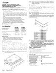
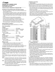
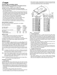
2. Insert the drive
Slide the carrier or tray into the appropriate bay in your host system. This
connects the drive directly to your system’s 40-pin Fibre Channel single
connector attachment (FC-SCA). The FC-SCA connector is normally
located on a Fibre Channel backpanel.
Note. There are no jumpers or terminators on the drive, and power is supplied through the 40-pin connector.
Cheetah 15K.4 FC Installation Guide
ST3146854FC, ST373454FC and ST336754FC
Fibre Channel interface disc drives
3. Connect LEDs (optional)
Note. This is an optional step. The drive will work fine without the LEDs
connected to the drive.
Publication Number: 100220460, Rev. B, February 2004
Handling precautions/Electrostatic discharge protection
• Disc drives are fragile. Do not drop or jar the drive. Handle the drive only
by the edges or frame.
• Drive electronics are extremely sensitive to static electricity. Keep the
drive in its antistatic container until you are ready to install it. Wear a wrist
strap and cable connected to ground. Discharge static from all items near
or that will contact the drive. Never use an ohmmeter on any circuit
boards.
• Turn off the power to the host system during installation.
• Always use forced-air ventilation when operating the drive.
• Use caution when troubleshooting a unit that has voltages present.
• Do not disassemble the drive; doing so voids the warranty.
• Return the entire drive for depot service if any part is defective.
• Do not apply pressure or attach labels to the circuit board or to the top of
the drive.
The drive supplies pins that you can use to connect fault and active LEDs.
This allows you to monitor drive fault conditions and activity. The actual LED
is external to the drive.
Drive
Front
Pin 1
J6
Reserved
Port A Bypass LED [1]
Electromagnetic compliance
Port B Bypass LED [1]
See the Safety and Regulatory Agency Specifications page, part number
75789512 which was shipped with this installation guide.
Fault LED [1]
Reserved
Drive characteristics
Active LED [2]
ST3146854FC
73.4 Gbytes
ST373454FC
36.7 Gbytes
ST336754FC
18.4 Gbytes
143,374,744
(88BB998h)
71,687,372
(445DCCCh)
35,843,686
(222EE66h)
Cylinders (user accessible) 31,310
31,310
31,310
Heads (user accessible)
8
4
2
Disc rotation +/– 5%
15,000 RPM
15,000 RPM
15,000 RPM
Formatted capacity
Total # of data blocks
Reserved
+5V
Active LED [1]
Ground [3]
• Screwdriver and four 6-32 UNC drive mounting screws
• Forced-air ventilation to provide adequate drive cooling
• Host system with Fibre Channel host adapter or backplane
[1] The drive has a 2.2K ohm resistor in series with this LED driver. Tie the
minus side of an external high-efficiency LED (i.e., 2ma) to this pin.
Connect the plus side of the LED to +5V.
[2] An external current-limiting resistor is required when connecting an
LED to this pin. The minus side of the resistor/LED combination is connected to this pin. Connect the plus side to +5V.
[3] Jumper storage location (across pins 2 and 4).
Installation instructions
Figure 2.
1. Mount the drive in the host system carrier or tray
Most Fibre Channel host systems (including enclosures) provide a way to
insert the drive using a carrier or tray which allows the drive to be hotplugged into the system’s Fibre Channel 40-pin single connector attachment (FC-SCA).
Fault LED Signal
The drive activates the fault LED Out signal when:
Mount the drive to the carrier or tray provided by the host system using four
6-32 UNC screws. Do not over-tighten or force the screws. You can mount
the drive in any orientation. See Figure 1.
Active LED signal
The drive activates the active LED signal as indicated below.
Note. FC drives are designed to be attached to the host system without I/O
or power cables.
Spun down and no activity.............. Slow blink (20% on and 80% off)
What you need
LED indicator connector
• the drive detects failure of both ports
• the drive detects an internal failure
• the drive receives the appropriate fault LED command from the host
Normal command activity
LED status
Spun down and activity................... On
(command executing)
Spun up and no activity .................. On
Spun up and activity ....................... Off
(command executing)
Spinning up or down....................... Blinks steadily (50% on and 50% off)
Format in progress ......................... Toggles on/off
(each cylinder change)
Figure 1.
Sample drive carrier
Note. Figure 1 above shows a generic carrier. Most carriers will look different than the one shown. Many are actually small enclosures rather
than brackets as shown here.
4. Format the drive
The drive has been low level formatted at the factory. You do not need to
perform another low level format on this drive unless you decide to perform
certain diagnostics through the host adapter. If you do decide to perform a
low level format, do not abort the format as this is likely to make the drive
inoperable. A low level format, with verify turned on, will typically take 30
minutes for ST336754FC models, 60 minutes for ST373454FC models, or
90 minutes for ST3146854FC models.
Protect against power failure or other power interruptions during the format.
a. Turn on DC power to the host system.
b. Boot the system from a system floppy, CD, or from a previously
installed hard disc drive if there is one.
c. Format the drive.
Caution. Formatting a drive erases all user data. Be sure that you understand this principle before formatting any hard disc drive. It is not
necessary to format a drive that previously has been used to
store data, unless your intention is to erase all user data.
Seagate® is not responsible for lost user data.
Cheetah® 15K.4 disc drives are designed to operate with a variety of operating systems. Please refer to your system or Fibre Channel host adapter
(controller) manual for information about formatting and setting up the drive
for use with your particular operating system.
Hot plugging the drive
This drive features hot plugging capabilities which allows you to insert and
remove the drive without powering down the host system. Any time a drive
is inserted or removed from a Fibre Channel loop, a short loop interruption
occurs and the loop resynchronizes automatically to accommodate the
added (or removed) drive.
Drive startup options
The drive’s motor will start spinning the discs based on the status of two signals set by the host adapter. These two signals are called Start_1 and
Start_2. There are four options as described below.
Option Start_2 Start_1
Seagate support services
For online information about Seagate products, visit www.seagate.com or
e-mail your disc questions to [email protected].
If you need help installing your drive, consult your dealer first. If you need
additional help, call a Seagate technical support specialist. Before calling,
note your system configuration and drive model number (ST3146854FC,
ST373454FC or ST336754FC).
Africa
Australia
Austria
Belgium
Denmark
France
Germany
Hong Kong
India
Indonesia
Ireland
Italy
Japan
Malaysia
Middle East
Netherlands
+31-20-316-7222
1800-14-7201
0 800-20 12 90
0 800-74 876
80 88 12 66
0 800-90 90 52
0 800-182 6831
800-90-0474
1-600-33-1104
001-803-1-003-2165
1 800-55 21 22
800-790695
0034 800 400 554
1-800-80-2335
+31-20-316-7222
0 800-732-4283
New Zealand
Norway
Poland
Spain
Sweden
Switzerland
Singapore
Taiwan
Thailand
Turkey
United Kingdom
USA/Canada/
Latin America
Other European
countries
0800-443988
800-113 91
00 800-311 12 38
900-98 31 24
0 207 90 073
0 800-83 84 11
800-1101-150
+886-2-2514-2237
001-800-11-0032165
00 800-31 92 91 40
0 800-783 5177
1-800 SEAGATE or
+1-405-936-1234
+31-20-316-7222
Warranty. Contact your place of purchase or our web site (above).
Return Merchandise Authorization (RMA). Before returning the drive, verify that it
is defective. Seagate Worldwide customer service centers are the only facilities authorized to service Seagate drives. Contact nearest center for return procedures and trade
regulations.
Shipping the drive
Caution. Back up the data before shipping. Seagate assumes no responsibility for
data lost during shipping or service. Shipping drive in an unapproved container voids
the warranty. Pack the drive with original box and packing materials. Use no other
materials. This prevents electrical and physical damage in transit.
Motor spin function
1 ........... Low ....... Low ........ Motor spins up at DC power on.
2 ........... High ...... Low ........ Motor spins up when the host adapter sends
the SCSI Start command.
3 ........... Low ....... High........ Motor spins up after a delay of 12 seconds
times the physical address of the drive.
4 ........... High ...... High........ The drive will not spin up.
Most systems that host only a couple of drives use option 1 to enable all of
the drives to start up immediately when power is applied to the drives. Systems hosting larger numbers of drives may be configured to start drives at
various times to avoid overloading the capabilities of the host system’s
power supply.
If you want to change the startup option for the drive, please refer to the
documentation provided with your Fibre Channel host adapter or host system.
Troubleshooting
• Drive does not spin up. Remove and then reinsert the drive into the
drive bay on the host-supplied carrier or tray. Make sure the drive makes
firm contact with the host’s FC backpanel connector. Also, check the
drive startup options for the Start_1 and Start_2 signals controlled from
your host adapter. See “Drive Startup Options” above for the four possible startup options.
• Computer does not seem to recognize the drive. Verify that the drive
is enabled by the FC host adapter setup utility.
© 2004 Seagate Technology LLC All rights reserved
Publication number: 100220460, Rev. B, February 2004, Printed in U.S.A.
Seagate and Seagate Technology are registered trademarks of Seagate Technology
LLC. Cheetah and the Wave logo are registered trademarks or trademarks of Seagate
Technology LLC. Other product names are registered trademarks or trademarks of
their owners. Seagate reserves the right to change, without notice, product offerings or
specifications.