1
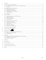
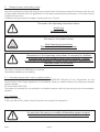
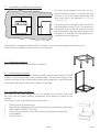
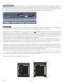
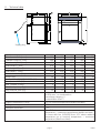
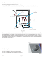
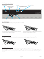
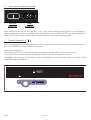
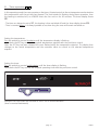
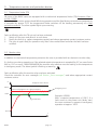
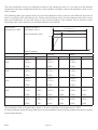
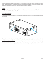
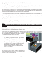
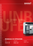
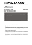
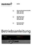
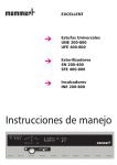
BASIC
Universal ovens
UNB 100-500
UFB 400-500
Sterilisers
SNB 100-400
SFB 400-500
Incubators
INB 200-500
Operating Instructions
Mo
Tu
We
Th
Fr
Sa
t3
Su
on
off
4
t4
t2
h
3
t1
loop
STERI
IN 1
DEFRO
°C
°C
2
1
PRINT
set
IN 2
OUT
%rh
mb
IN 1
IN 2
OUT
CO2
mb
MAX
MIN
AUTO
SETUP
on
off
page 1
BASIC
BASIC
page 2
1.
Contents ....................................................................................................................................... 3
2.
General notes and safety notes ......................................................................................................4
2.1. Intended purpose when used as medical product .................................................................. 4
2.2 Transport ..............................................................................................................................4
3.
Installation facilities (accessories)....................................................................................................5
3.1 Subframe (accessory) .............................................................................................................5
3.2 Wall bracket (accessory) ........................................................................................................5
3.3 Stackable version (accessory) .................................................................................................5
3.4 Initital start-up ......................................................................................................................6
3.5 Oven load .............................................................................................................................6
4.
Technical data................................................................................................................................ 7
4.1 Standard equipment of BASIC ovens......................................................................................8
4.2 Material quality .....................................................................................................................8
4.3 Electrical equipment ..............................................................................................................9
4.4 Supply failurel .......................................................................................................................9
5.
Oven construction and operation .................................................................................................10
5.1 Operating the door .............................................................................................................10
5.2 Controls and indications ......................................................................................................11
5.3 Switching on .......................................................................................................................11
5.4 Setting air changes ..............................................................................................................11
5.5 Setting the temperature ......................................................................................................11
6.
Selecting the operating mode ......................................................................................................12
7.
Normal operation
8.
Timer operation
9.
Temperature monitor and protection devices................................................................................14
9.1 Temperature limiter (TB) ......................................................................................................14
9.2 Monitor relay ......................................................................................................................14
............................................................................................................12
................................................................................................................13
10. Sterilisers ..................................................................................................................................... 15
10.1 Purpose definition for MEMMERT hot air sterilisers .............................................................. 15
10.2 Guidelines for sterilisation ...................................................................................................15
10.3 Steriliser cassettes................................................................................................................17
11. Cleaning ...................................................................................................................................... 18
12. Maintenance ...............................................................................................................................18
13. Error messages ............................................................................................................................19
14. CE Conformity Declaration ...........................................................................................................20
15. Address and customer service ......................................................................................................23
16. Index ........................................................................................................................................... 24
1.
Contents
page 3
BASIC
2.
General notes and safety notes
You have purchased a technically fully proven product which has been produced in Germany with the use
of high-grade materials and the application of the latest manufacturing techniques; it has been factory
tested for many hours.
In addition we guarantee the supply of spare parts over 10 years.
This mark in the Operating Instructions means:
Watch out
Important Note!
This mark on the product means:
Note Operating Instructions
Warning – oven hot when operating!
Observation of the Operating Instructions is necessary for faultless
operaton and for any possible claims under warranty. If these
Instructions are disregarded, all claims under warranty, guarantee and
indemnification are excluded!
The right to technical modifications is reserved.
Dimensional details are not binding.
2.1. Intended purpose when used as medical product
For ovens covered by the scope of the Directive 93/42/EWG (Directive of the Commission on the
harmonization of the legal regulations of the Member States on medical devices) the following intended
purpose applies:
For ovens series SNB / SFB:
The product is intended for the sterilisation of medical products with dry heat using hot air at atmospheric
pressure.
2.2 Transport
Always use gloves!
If the oven has to be carried, at least 2 persons are required to transport it.
Do not place the oven on a readily inflammable support surface!
It is important that the oven is set up accurately horizontally!
BASIC
page 4
Installation facilities (accessories)
The oven can be placed on the floor or on a
bench (working surface). It is important that
the oven is set up accurately horizontally; the
door may have to be adjusted (see Section
„Maintenance“)
min.
20 cm
3.
8 cm
8 cm
15 cm
min.
min.
min.
The spacing from the back of the oven to the
wall should be at least 15 cm. The spacing to
the ceiling must not be less than 20 cm and
that at the side to the wall not less than 8 cm.
Generally it is essential to have adequate air
ventilation around the oven.
Information on accessories will be found in our leaflet or on our internet page www.memmert.com.
Please note the installation instructions for our accessories.
3.1 Subframe (accessory)
Oven model 500 can be mounted on a subframe
3.2 Wall bracket (accessory)
Ovens models 200 to 500 can be wall-mounted using the wall bracket. The wall
bracket is factory-fitted with a fire-resistant plate. The size and length of the
screws used and of the corresponding dowel plugs depend on the total weight
(oven plus load) and vary with the condition of the wall.
3.3 Stackable version (accessory)
Two ovens of the same model size can be stacked on each other. Note that
the oven with the lower working temperature must always be placed at the
bottom.
Foot locators have to be fitted on the bottom oven.
•
•
•
•
•
Take off cover of bottom oven
Place drill jig (supplied with foot locators) into the inverted cover at the back
Mark holes and drill 4.2 mm dia.
Screw the foot locators to the top of the cover using the screws and
nuts supplied
Re-fit the cover
page 5
BASIC
3.4 Initital start-up
When the oven is started up for the first time, it should be supervised continuously until steady conditions
have been reached. Severe vibrations during transport may cause movement of the temperature probe in
its holder inside the chamber. Note therefore that before the first start-up the temperature probe should
be checked for its correct position and, if necessary, carefully aligned in its mounting (see ill).
Ill: Chamber ceiling with Pt 100 metal temperature probe
3.5 Oven load
Full consideration must be given to the physical and chemical properties of your load (e.g. combustion
temperature etc.) in order to prevent serious damage to load, oven and surroundings.
Please note that the MEMMERT ovens described here are not explosionproof (they do not conform to the
Industrial Association Specification VBG 24) and are therefore not suitable for drying, evaporating and
burning-in of paints, enamels or similar materials whose solvents may produce an inflammable mixture
with air. There must be no possibility of the formation of inflammable gas/air mixtures either within the
oven chamber or in the immediate surroundings of the equipment.
Large amounts of dust or corrosive fumes inside the oven chamber or in the surroundings of the equipment
may produce deposits within the oven and lead to short-circuits or damage the electronics. It is therefore
important that adequate precautions are taken against excessive dust or corrosive fumes.
In order to ensure proper air circulation inside the chamber, there must be sufficient spacing of the load
inside the oven. Do not place any load on the floor, against the side walls or underneath the ceiling of the
chamber (heating ribs). In order to ensure optimum air circulation the shelves must be so inserted that the
air spacings between door, shelf and rear chamber wall are approximately equal.
The maximum number and the loading of the shelves can be found in the table in the Section „Technical
Data“. With unfavourable loading (too closely spaced) and completely opened ventilation it is possible that
the set temperature may be reached only after a longer period of time.
See stick-on label “Correct Loading“ on the oven!
BASIC
page 6
4.
Technical data
Supply plug
Model
Chamber width A [mm]
Chamber height B [mm]
Chamber depth C [mm]
Oven width D [mm]
Oven height E [mm]
Oven depth F [mm]
Chamber volume [litre]
Weight [kg]
Power, ovens UNB/UFB/SNB/SFB [W]
Power, ovens INB [W]
Max. number of trays
Max. load per tray [kg]
Total load per oven [kg]
Ambient conditions
Setpoint temperature range
Setting accuracy
Indication resolution
Working temperature range
100
200
300
400
500
320
400
480
400
560
240
320
320
400
480
175
250
250
330
400
470
550
630
550
710
520
600
600
680
760
325
400
400
480
550
14
32
39
53
108
20
28
30
35
50
600
1100
1200
1400
2000
300
440
500
800
900
2
3
3
4
5
10
15
12
30
30
20
30
30
90
60
Ambient temperature 5°C to 40°C
rH 80% max., no condensation
Overvoltage category: II
Contamination level: 2
20°C to nominal temperature (details see label)
0,5°C
0,5°C
From 5°C above ambient temperature up to nominal
temperature = maximum temperature (details see label)
On ovens with fan (UFB/SFB) from 10°C above ambient
temperature up to nominal temperature = maximum
temperature (details see label)
page 7
BASIC
4.1 Standard equipment of BASIC ovens
•
Electronic PID controller with permanent power matching, auto-diagnostic system for rapid fault
finding (see Section “Error messages“)
•
Manually adjustable air valve for recirculation or fresh air operation
•
Programmable electronic switch-off timer up to 99 h 59 min
•
Recessing push/turn control for simple operation of oven
•
Visual alarm indication
•
Monitor relay to switch off heating in case of fault
•
Mechanical temperature limiter (TB Class 1)
•
High-grade PT100 temperature sensor Class A in 4-wire circuit
•
Special equipment (to be ordered separately as accessories): subframe, wall bracket, sterilisation
cassette
4.2 Material quality
For external casing and working chamber MEMMERT are using stainless steel (Mat.Ref. 1.4301) which
features high strength, optimum hgygienic properties and corrosion resistance against many (not all)
chemicals (warning against e.g. chlorine compounds).
The oven load has to be checked carefully for its chemical compatibility with the above materials.
A compatibility table covering all these materials can be requested from MEMMERT.
BASIC
page 8
WARNING! Always pull out the supply plug before opening the oven
cover!
4.3
•
•
•
•
•
•
•
•
•
Electrical equipment
Operating voltage see label 50/60 Hz
Current rating see label
Protection Class 1, i.e. operating isolation with ground connection to EN 61 010
Protection IP20 to EN 60 529
Interference suppression to EN55011 Class B
Oven protected by a fuse 250V/15A fast blow
Controller protected by an 80 mA fuse (200 mA on 115 V)
When connecting a MEMMERT oven to the electrical supply you have to observe any local
regulations which apply (e.g. in Germany DIN VDE 0100 with FI protection circuit)
This product is intended to operate on a supply network with a system impedance Zmax at the
transfer point (building connection) of 0.292 Ohm max. The user has to ensure that the product is
only operated on an electrical supply network which meets these requirements. If necessary, details
of the system impedance can be obtained from the local electricity supply authority.
Note:
Any work involving opening up the oven must only be carried out by a suitably qualified
electrician!
4.4 Supply failurel
After a failure of the supply, operation is continued with the same parameter settings.
page 9
BASIC
5.
Oven construction and operation
Ovens Series UNB, INB and SNB have natural ventilation.
In Series UFB amd SFB ovens, air circulation is provided by a fan on the back wall of the chamber.
4
chamber
6
air valve
7
air discharge
3
ventilation slots
5
fan
1
air supply
fresh air
2
preheat chamber
The incoming air (1) is warmed in a preheat chamber (2) in both convection and fan-circulation ovens. The
preheated air enters the chamber (4) through ventilation slots (3) in the chamber side wall. The fan (5) on
the chamber back wall produces a large air throughput and a more intensive horizontal forced circulation
compared with natural convection. The air valve (6) on the back of the oven controls the rate of air intake
and discharge (air change) (7).
close
5.1 Operating the door
The door is opened by pulling on the door handle.
The door is closed by the door handle being pushed in.
open
BASIC
page 10
5.2 Controls and indications
timer display
heating
operating mode
indication
Mo
Tu
We
Th
Fr
Sa
4
t4
t2
h
temperature display
t3
Su
on
off
3
t1
alarm indication
loop
STERI
IN 1
DEFRO
°C
2
set
OUT
%rh
mb
IN 1
IN 2
OUT
CO2
mb
MAX
1
PRINT
set-key
IN 2
°C
MIN
AUTO
SETUP
on
off
push/turn control
(main switch)
Ill : UNB 500
air slider
5.3 Switching on
The oven is switched on by pressing the push/turn control.
Oven switched off. The push/turn control is pushed
in and protected against damage
Oven switched on and can be operated using the
push/turn control and the SET key.
5.4 Setting air changes
Moving the air slider opens and closes the air valve to control the supply and discharge of air.
Air valve closed
Air valve open
5.5 Setting the temperature
Hold down the SET key and set the temperature setpoint with the push/turn control.
After the SET key has been released the display briefly flashes the temperature setpoint. The display then
changes to the actual current temperature and the controller starts to control to the selected temperature
setpoint.
page 11
BASIC
6.
Selecting the operating mode
Normal
operation
Timer
operation
After holding down the SET key (approx. 3 sec), the current operating mode flashes on the display. A
different operating mode can be selected with the push/turn control while the SET key is being held down.
After the SET key has been released the controller operates in the new operating mode.
7.
Normal operation
In this operating mode the oven operates continuously and heats and controls to the set temperature. On
the ovens UFB/SFB the fan is running continuously.
Setting the temperature:
Hold down the SET key and set the required temperature setpoint with the push/turn control.
After the SET key has been released the display flashes briefly the temperature setpoint.
The display then changes to the actual current temperature and the controller starts to control to the
selected temperature setpoint.
h
BASIC
˚C
page 12
8.
Timer operation
In this operating mode the oven operates on the timer; it heats/controls to the set temperature and maintains
this temperature until the set time has elapsed. The clock symbol is flashing during timer operation, then
the heating is switched off; on UFB/SFB ovens the fan runs on for 30 minutes. The timer display shows
END.
- The time can always be set to OFF, the heating is then switched off and the timer display shows END.
- Time is counted down, it is always possible to see how long the oven will remain switched on.
Setting the temperature:
Turn the push/turn control clockwise until the temperature display is flashing.
Hold down the SET key and set the required temperature setpoint with the push/turn control.
After the SET key has been released the oven flashes briefly the temperature setpoint. The display then
changes to the actual temperature and the controller starts to control to the selected temperature
setpoint.
Setting the timer:
Turn the push/turn control anticlockwise until the timer display is flashing.
Hold down the SET key and set the required operating time with the push/turn control.
h
˚C
Example: the oven heats and controls at 180°C for 45 minute duration.
(time is counted backwards)
page 13
BASIC
9.
Temperature monitor and protection devices
9.1 Temperature limiter (TB)
All ovens of the BASIC series are equipped with a mechanical temperature limiter (TB) Protection Class 1
to DIN 12 880.
If the electronic monitor system should fail during operation and the fixed factory-set maximum temperature
is exceeded by approx. 20°C the temperature limiter switches off the heating permanently as a final
protective measure. The alarm symbol lights up as warning.
Fault rectification after the TB cut-out has been activated:
1.
Switch off the oven and allow it to cool down
2.
Rectify the fault (e.g. replace temperature probe) and where appropriate contact customer service
3.
The oven is again ready for operation only after it has cooled down and after the fault has been
rectified.
9.2 Monitor relay
In addition to mechanical temperature protection the oven is provided with an electronic monitor relay.
If a fault occurs during operation or if the selected setpoint temperature is exceeded (by 3°C on ovens Series
INB, by 10°C on ovens UNB/UFB/SNB/SFB) the monitor relay switches over the heating to this temperature
in emergency mode. The alarm symbol is flashing as warning.
Fault rectification after the monitor relay may been activated:
Check the controller for error messages (see Section „Error messages“) and where appropriate contact
customer service.
°C
TB approx. 20°C above
220°C
emergency mod
monitor relay approx. 10°C above setpoint
150°C
setpoint
control fault
20°C
t
BASIC
page 14
Example: UFB500:
With a setpoint temperature of 150°C, if a
fault occurs in the power unit (faulty triac)
the oven continues to operate in emergency
operation at approx. 160°C.
10. Sterilisers
10.1 Purpose definition for MEMMERT hot air sterilisers
The oven SNB/SFB is intended for the sterilisation of medical materials by dry heat using hot air at atmospheric
pressure.
10.2 Guidelines for sterilisation
For hot air sterilisation there are different regulations covering the temperature settings and the sterilisation
times, as well as the packaging of the products to be sterilised. The values depend on the type and condition
of the load to be sterilised and on the type of bacteria which have to be de-activated. Please make yourself
familiar with the sterilisation method laid down for your application before carrying out sterilisation using
your MEMMERT cabinet.
The operation of the MEMMERT hot air steriliser is also subject to the Standard DIN 58 947 Part 6.
A few examples of the correct preparation for different medical products are summarised in the following
table:
Load
Preparation
Instruments (no soft solder)
load cleaned instruments, wrapped twice in aluminium foil or in
steriliser foil suitable for hot air (recommended)
load cleaned instruments, wrapped twice in aluminium foil or in
steriliser foil suitable for hot air (recommended)
load plunger and cylinder separately, wrapped twice in aluminium
foil or in steriliser foil suitable for hot air (recommended)
dismantle cleaned glass vessels and all-glass syringes and place into
dishes, cool down slowly
Cutting instruments
Syringes (no plastics)
Glass and glass instruments
Bottles, vessels and similar items must be sterilised without closure and with the opening downwards, in
order to avoid the formation of cold air pockets. The recommended sterilisation temperature is usually
180°C (German Pharmacopoeia DAB 10)
page 15
BASIC
The total sterilisation time to be selected consists of the heating-up time (i.e. the time until the desired
temperature has been established within the entire steriliser chamber), the actual sterilisation time, and a
safety margin.
The following table gives typical values for the total sterilisation time to be set, with different amounts of
load, for sterilisers with and without fan. Please note that these values can be employed only with correct
and loose distribution of the load. Notes on the correct loading of the steriliser can be found in these
Operating Instructions and also on the label affixed to the steriliser.
Sterilisation
temperature:180°C
heating-up time +
sterilisation time =
°C
total sterilisation time
heating-up time
sterilisation time
total sterilisation time
180°C
t
Type of loading:
light
medium
Steriliser size
without fan
with fan
without fan
with fan
without fan
with fan
----
0:45h+
1:15h=
----
0:45h+
1:45h=
----
100
0:45h+
0:45h=
200
1:30h
0:45h+
0:45h=
300
1:30h
0:45h+
0:45h=
400
1:30h
0:45h+
1:15h=
500
----
2:00h
0:45h+
1:15h=
----
2:00h
0:45h+
1:15h=
0:30 h+
1:00h=
2:00h
0:45h+
1:45h=
2:00h
0:45h+
1:15h=
1:30h
0:30 h+
1:00h=
2:00h
1:30h
heavy
----
2:30h
0:45h+
1:45h=
----
----
2:30h
0:45h+
1:45h=
----
0:45 h+
1:15h=
2:30h
1:00 h+
2:00h=
0:45 h+
1:45h=
2:30h
0:45h+
1:45h=
2:00h
0:45 h+
1:15h=
3:00h
1:00 h+
2:00h=
2:30h
0:45 h+
1:45h=
2:30h
2:00h
3:00h
2:30h
The sterilisation time is increased by a factor of 4 when sterilising at a temperature of 160°C.
On large sterilisers and with heavy loading it is recommended to use wire shelves (special accessory) instead
of perforated shelves.
BASIC
page 16
Especially with heavy loading of the steriliser it is not sufficient to use these typical values without further
tests. Reliable sterilisation requires validation of the individual sterilisation process, e.g. with the aid of
additional temperature probes or by using biological or chemical indicators.
Note:
In sterilisation processes the vent valve on the oven must be closed after the moist
sterilisation load has been dried!
10.3 Steriliser cassettes
The cassettes should preferably be so arranged in the steriliser that the hot air flow can pass readily through
the air slots.
1
2
The load to be sterilised is placed into the steriliser cassettes wrapped in aluminium foil or in steriliser foil
suitable for hot air (as in the Table in the Section „Guidelines for sterilising“). The air slots in the cassette
must be open during sterilisation.
A temperature probe to confirm the temperature of the load can be introduced through the opening (2).
After sterilisation has been completed the air slots must be closed by moving the slide knob (1).
page 17
BASIC
The sterilised and packed load can then be stored briefly in the closed cassette.
11. Cleaning
Regular cleaning of the easy-to-clean inside of the chamber prevents deposits which over time can detract
from the appearance and the functionality of the stainless steel chamber .
The metal surfaces of the oven can be cleaned with commercially available cleaning agents for stainless
steel. It is important to ensure that no rust-forming object comes into contact with the chamber or the
stainless steel casing. Rust deposits cause infection of the stainless steel.
If any contamination causes rust stains on the surfaces of the chamber, such spots must be cleaned off
immediately and the area polished.
The control panel, the plastic input modules and other plastic components of the oven must not be cleaned
using scouring cleaning agents or those contained solvents.
12. Maintenance
Important for a long life of your MEMMERT product and in case of warranty claims.
Note:
Any work involving opening up the oven must only be carried out by a suitably qualified
electrician!
MEMMERT products require little maintenance. It is however recommended to lubricate all moving parts
of the doors (hinges and closure) once a year (or 4 times a year with continuous operation) using a thin
Silicone grease, and to check that the hinge screws are tight.
A well-closing door is essential on an oven. On Memmert ovens, tight closure of the door is ensured by a
seal on the oven and another one on the door. In continuous operation the flexible sealing material may
take a permanent set. Readjustment may then be necessary
in order to ensure proper closing of the door.
•
The top part (1) of the door hinge can, after releasing
the 2 screws (2) at the top or bottom of the door, be
moved slightly in the direction of the arrow.
•
The door can be adjusted after releasing the socket
screw (3) and rotating the excentric (4) by means of
a screwdriver. NOTE ! Screw (3) is locked with locking
varnish. It can be released by a sharp tug using a
hexagon socket key. Apply more locking varnish to
screw (3) and tighten it.
The closing panel (6) can also be adjusted in the direction of
the arrow after releasing the screw (5). It is important that
the panel is then screwed down firmly.
BASIC
page 18
1
2
4
3
5
6
13. Error messages
E-0
E-1
E-2
E-3
Error on self test
Power module triac faulty
Power module faulty
PT100 temperature probe faulty
In case there is a fault on the oven, please get in touch with an authorised service organisation
or contact the MEMMERT customer service department.
When dealing with the service department always quote the product serial number on the oven label.
page 19
BASIC
14. CE Conformity Declaration
EC Declaration of Conformity
Manufacturer´s name and address:
MEMMERT GmbH + Co. KG
Äußere Rittersbacher Straße 38
D-91126 Schwabach
Universal oven
UNB … / UFB … / UNE ... / UFE … / UNP … / UFP …
100 / 200 / 300 / 400 / 500 / 600 / 700 / 800
AC 230 V or 3 ~ AC 400 V 50 / 60 Hz
alternative AC 115 V 50/60 Hz
Product:
Type:
Sizes:
Nominal voltage:
The designated product is in conformity with the European EMC-Directive
89/336/EEC
including amendments
Council Directive of 03 May 1989 on the approximation of the laws of the Member States relating to
electromagnetic compatibility.
Full compliance with the standards listed below proves the conformity of the designated product with the essential
protection requirements of the above-mentioned EC Directive:
DIN EN 61 326 (VDE 0843 part 20): 1998-01
DIN EN 61 326/A1 (VDE 0843 part 20/A1): 1999-05
RFI suppression: Class B
DIN EN 61 000-3-11 (VDE 0838 part 11): 2001-04
EN 61 326: 1997
EN 61 326: 1997/A1 : 1998
EN 61 000-3-11: 2000
The designated product is in conformity with the European Low Voltage Directive
73/23/EEC
including amendments
Council Directive on the approximation of the laws of the Member States relating to Electrical
equipment for use within certain voltage limits.
Full compliance with the standards listed below proves the conformity of the designated product with the essential
protection requirements of the above-mentioned EC Directive:
DIN EN 61 010-1 (VDE 0411 part 1): 1994-03
DIN EN 61 010-2-010 (VDE 0411 part 2-010): 1995-03
EN 61 010-1: 1993
EN 61 010-2-010: 1994
Schwabach, 25.07.05
(Legally binding signature of the issuer)
This declaration certifies compliance with the above mentioned directives but does not include a property assurance. The
safety note given in the product documentation which are part of the supply, must be observed.
D09932 / 25.07.05
BASIC
page 20
EC Declaration of Conformity
Manufacturer´s name and address:
MEMMERT GmbH + Co. KG
Äußere Rittersbacher Straße 38
D-91126 Schwabach
Incubators
INB … /INE … / INP …
200 / 300 / 400 / 500 / 600 / 700 / 800
AC 230 V 50/60 Hz
alternative AC 115 V 50/60 Hz
Product:
Type:
Sizes:
Nominal voltage:
The designated product is in conformity with the European EMC-Directive
89/336/EEC
including amendments
Council Directive of 03 May 1989 on the approximation of the laws of the Member States relating to
electromagnetic compatibility.
Full compliance with the standards listed below proves the conformity of the designated product with the essential
protection requirements of the above-mentioned EC Directive:
DIN EN 61 326 (VDE 0843 part 20): 1998-01
DIN EN 61 326/A1 (VDE 0843 part 20/A1): 1999-05
RFI suppression: Class B
DIN EN 61 000-3-11 (VDE 0838 part 11): 2001-04
EN 61 326: 1997
EN 61 326: 1997/A1 : 1998
EN 61 000-3-11: 2000
The designated product is in conformity with the European Low Voltage Directive
73/23/EEC
including amendments
Council Directive on the approximation of the laws of the Member States relating to Electrical
equipment for use within certain voltage limits.
Full compliance with the standards listed below proves the conformity of the designated product with the essential
protection requirements of the above-mentioned EC Directive:
DIN EN 61 010-1 (VDE 0411 part 1): 1994-03
DIN EN 61 010-2-010 (VDE 0411 part 2-010): 1995-03
EN 61 010-1: 1993
EN 61 010-2-010: 1994
Schwabach, 25.07.05
(Legally binding signature of the issuer)
This declaration certifies compliance with the above mentioned directives but does not include a property assurance. The
safety note given in the product documentation which are part of the supply, must be observed.
D09937 / 25.07.05
page 21
BASIC
EC Declaration of Conformity
Manufacturer´s name and address:
MEMMERT GmbH + Co. KG
Äußere Rittersbacher Straße 38
D-91126 Schwabach
Product:
Type:
Steriliser
SNB … / SFB … / SNE … / SFE … / SFP …
100 / 200 / 300 / 400 / 500 / 600 / 700 / 800
AC 230 V or 3 ~ AC 400 V 50 / 60 Hz
alternative AC 115 V 50/60 Hz
Sizes:
Nominal voltage:
The product meets the regulations of the directive
93/42/EWG
Directive of the council to adapt legal regulations of the member states on the subject
of medical products dd. 14.06.1993 (Abl. EG Nr. L 169, S. 1, 12.07.1993) including
annex and modifications.
Schwabach, 25.07.05
(Legally binding signature of the issuer)
This declaration certifies compliance with the above mentioned directives but does not include a property assurance.
The safety note given in the product documentation which are part of the supply, must be observed.
D09970
BASIC
page 22
Standard ovens (UNB / UFB / INB) are safety-approved and bear the test marks:
Sterilisers (SNB / SFB) are safety-approved and bear the test marks:
1275
This product is subject to the Directive 2002/96/EC by the European
Parliament and the EU Council of Ministers which concerns Waste Electrical
and Electronic Equipment (WEEE). This product has been put on the market
after 13 August 2005 in countries which have already incorporated this
Directive into National Law. It should not be disposed off as part of domestic
refuse. For disposal please contact your dealer or the manufacturer. Products
which are infected, infectious or contaminated with health-endangering
substances are excluded from return. Please note also all further regulations
in this context.
15. Address and customer service
MEMMERT GmbH+Co.KG
PO Box 17 20
91107 Schwabach
Germany
Phone: 00 49 9122 / 925-0
Fax:: 00 49 9122 /14585
E-mail: [email protected]
Internet: www.memmert.com
Customer service:
Phone: 00 49 9122 / 925-143
or 00 49 9122 / 925-126
E-mail: [email protected]
When contacting customer service, always quote the
product serial number on the oven label.
page 23
BASIC
16. Index
A
N
accessories 9
address 23
air changes 11
air slider 11
air supply 10
air valve 10
alarm indication 11
alarm symbol 14
normal operation 12
C
CE conformity declaration 20
cleaning 18
construction, oven 10
customer service 23
D
DIN 12 880 14
display, temperature 11
display, timer 11
door 10
door handle 10
E
error messages 19
F
failure, supply 8. 19
fan 10
fan indication 11
I
initial start-up 5
installation facilities 9
L
limiter, temperature 14
load 5
M
main switch 11
maintenance 18
material quality 4, 7
medical product 4
monitor relay 14
BASIC
O
operating mode indication 11
operating mode selection 12
operating time 13
operation 10
P
Protection Class 1 14
protection devices 14
purpose, intended 4, 15
push/turn control 11
R
relay, monitor 14
S
safety notes 4
SET key 11, 12, 13
stacking 9
start-up, initial 5
steriliser cassettes 17
sterilisers 15
subframe 9
supply failure 8, 19
T
TB 14
temperature 11
temperature display 11
temperature limiter 14
temperature monitor 14
temperature probe 5
temperature setpoint 11
timer display 11
timer operation 13
transport 4, 5
W
wall bracket 9
page 24
page 25
BASIC
Notes:
BASIC
page 26
page 27
BASIC
09.09.2005
BASIC englisch
D09803
BASIC
page 28