1
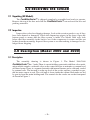
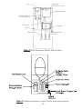
VERTEX
Water Products
PureWaterCooler
Water Dispenser
OWNERS INSTALLATION
MANUAL
Models
PWC3000/2000/600
3 Temp - Room, Hot, Cold
PWC1000/1010/500
2 Temp - Hot, Cold
VERTEX WATER PRODUCTS
Montclair, CA - USA
™
WARNING
1) Installing this cooler in an area were water may cause severe or costly damage is not recommended. If Installation of this cooler is in an area where incidental
water spillage may cause severe or costly damage it is recommended that a water
detector and shut-off valve accessory be installed as well. Vertex P/N LC-8021
2) Water supply connection to coolers are to be made with the flexible plastic
tubing provided. If connecting a hard copper line to cooler connection the Bulkhead
fitting on back of cooler must be replaced with a proper metal fitting.
3) Do not position the cooler where it can be hit or bumped by Vacum cleaners
or floor waxing machines This can cause breaks in the waterline, connection fittings
and compressor tubing.
Table of Contents
1.0 Introduction . . . . . . . . . . . . . . . . . . . . . . . . . . . . . . . . . . . . . . . . . . . . . pg. 2
2.0 Receiving . . . . . . . . . . . . . . . . . . . . . . . . . . . . . . . . . . . . . . . . . . . . . . . pg. 3
3.0 Description, Model 2000 and 3000 . . . . . . . . . . . . . . . . . . . . . . . . . . pg. 3
4.0 Operation . . . . . . . . . . . . . . . . . . . . . . . . . . . . . . . . . . . . . . . . . . . . . . . pg. 10
5.0 Description, Model 1000 and Model 1010 . . . . . . . . . . . . . . . . . . . pg. 12
6.0 Other Models 500/600/1000RF . . . . . . . . . . . . . . . . . . . . . . . . . . . . . pg. 15
7.0 Optional Features . . . . . . . . . . . . . . . . . . . . . . . . . . . . . . . . . . . . . . . . pg. 16
8.0 Filter Replacement . . . . . . . . . . . . . . . . . . . . . . . . . . . . . . . . . . . . . . . pg. 16
9.0 Cleaning and Maintenance . . . . . . . . . . . . . . . . . . . . . . . . . . . . . . . . pg. 18
10.0 Trouble Shooting . . . . . . . . . . . . . . . . . . . . . . . . . . . . . . . . . . . . . . . . . pg. 19
11.0 Specifications . . . . . . . . . . . . . . . . . . . . . . . . . . . . . . . . . . . . . . . . . . . . pg. 20
12.0 Warranty . . . . . . . . . . . . . . . . . . . . . . . . . . . . . . . . . . . . . . . . . . . . . . . pg. 21
List of Figures
Figure 1. Assembly Drawing, Model PWC 2000 and PWC 3000 . . pg. 4
Figure 2. Flow Schematic . . . . . . . . . . . . . . . . . . . . . . . . . . . . . . . . . . . . pg. 5
Figure 3. Filter Schematic . . . . . . . . . . . . . . . . . . . . . . . . . . . . . . . . . . . . pg. 5
Figure 4. Installation Precautions . . . . . . . . . . . . . . . . . . . . . . . . . . . . . pg. 6
Figure 5. Water Connections . . . . . . . . . . . . . . . . . . . . . . . . . . . . . . . . . pg. 7
Figure 6. Drain Connections for RO filter . . . . . . . . . . . . . . . . . . . . . . pg. 8
Figure 7. Quick Connect Fittings . . . . . . . . . . . . . . . . . . . . . . . . . . . . . . pg. 9
Figure 8. Model 1000 Assembly . . . . . . . . . . . . . . . . . . . . . . . . . . . . . . . pg. 12
Figure 9. Water Connection / 1000 . . . . . . . . . . . . . . . . . . . . . . . . . . . . pg. 13
Figure 10. Front of Model 1000 cooler with door opened . . . . . . . . . . pg. 14
Figure 11. RO Membrane Installation . . . . . . . . . . . . . . . . . . . . . . . . . . pg. 17
–1–
1.0 INTRODUCTION
The VERTEX Pure Water Cooler products are a means to produce and dispense
good-tasting, safe water without using “bottles of stored water”.
The Pure Water Cooler taps into your city or well water supply to efficiently filter out tastes and odor, and to remove molecular contaminants by using reverse
osmosis technology: The Models are:
2000 and 3000 Model. These are 3-temperature units which provides room temperature filtered water, chilled (cold) water, nominally at 44ºF, and hot water, nominally at 180ºF. In addition, it has a re-boil function which brings the hot water to boil
temperature of 212ºF. There is also a room temperature spigot.
1000 Model. This is a two temperature unit which provides chilled water nominally at 44ºF and dispenses hot water at nominally 180ºF.
1010 Model. This provides chilled water at nominally 44ºF and room temperatures. No hot water is provided.
All three models are made as “R” or “F” versions. The “R” versions have reverse
osmosis filtration which makes good tasting, safe water from city or well water. This
consists of a 5-micron sediment filter, a carbon (GAC) 10-micron filter and a 50-gallon per day RO membrane. The filters remove sediment and dirt and the taste and
odor of chlorine and other contaminants. The reverse osmosis stage removes molecular contaminants from the water. The “R” version requires a drain line connection
to the drain trap to remove rejected water to the sewer.
The “F” version has the sediment and carbon filters, but not the RO membrane;
therefore, it does not require a drain line connection.
CAUTION: The filter version “F” must be used only with softened water or
water that has less than 3.5-grains of hardness to prevent scaling and premature
burnout of the heating elements.
There are 3 other models, all versions of the basic models described above:
500 Model. This is a countertop model of the Model 1000 2temperature system.
600 Model. This is a countertop model of the Model 2000 3temperature system.
1000R/F Model. This is a Model 1000 2-temperature model with a
0.5 cu. ft. refrigerator at the bottom of the cabinet
instead of a filter.
The above three models do not have filters; they require that the pure water be
made externally and supplied to the Pure Water Cooler. An option is available which
adds a filterpack system that can be mounted on the backside of the cooler.
Please read all the instructions in this manual before operating this unit.
–2–
2.0 RECEIVING THE COOLER
2.1 Unpacking (All Models)
The PureWaterCooler™ is shipped completely assembled and ready to operate.
Remove the top of the box and slide the PureWaterCooler™ out and save the box and
packing materials.
2.2 Inspection
Inspect the cooler for shipping damage. Look at the exterior panels to see if they
have been dented or damaged. Check the dispensing spigots in the front. Open the
bottom panel to assure that the filter system is intact. For Model 2000 only look
below the filter assembly in the back to see if the compressor is secure and has not
broken from the mounting. Inspect filter system to see that nothing is damaged or dislodged from shipping.
3.0 Description (Model 2000 and 3000)
3.1 Description
The assembly drawing is shown in Figure 1. The Model 2000/3000
PureWaterCooler™ has 3 tanks There is a main holding water tank with float valve mechanism which controls a solenoid valve on the water feed line to maintain a constant level
of filtered water. There is a separate hot tank with internal heaters and a cold tank, cooled
by external coils. The hot tank is at the top level of the cooler, and has a vent hole to permit hot water vapors to exit. The cold tank is lower inside the cabinet. Both tanks are fed
by gravity from the main holding tank. The controls for the cooler are on the front panel
as shown in Figure 1.
– 3–
COVER
SNAP-ON
TOP COVER
STEAM EXHAUST
COVER
MAIN WATER
TANK COVER
HOT WATER
TANK COVER
CONTROL PANEL
MAIN WATER
TANK
MAIN OUTLET
TUBE
HOT WATER
TANK
WATER LEVEL INDICATOR
CONTROL PANEL
COLD WATER
RELEASE LEVER
ROOM WATER
RELEASE LEVER
HOT WATER
RELEASE LEVER
CUP BASE
SNAP-ON
FRONT PANEL RELEASE BUTTONS
Figure 1 Assembly Drawing PWC 2000 & PWC 3000
The internal flow of water to the tanks and dispensers is shown in Figure 2. The
arrangement of the water filter system in the bottom of the cabinet is shown in Figure 3.
This is where ordinary city or well water is converted into good tasting, clean, safe
drinking water.
–4–
Vent
Float Type
Water Level Control
Main Water Tank
Electric Heating
Coil Inside Tank
Check Valve
Cold Tank
Drain
Water Spigots
Purified Water Inlet
(from filters)
Hot
Room Cold
Figure 2 Flow Schematic (Model 2000 & 3000)
Figure 3 Filtration Schematic. Front of cooler with panel removed.
– 5–
3.2 Positioning the Cooler
There are some precautions in locating and using the PureWaterCooler™. See
the items in Figure 4 below. In addition, the cooler must be located near the supply
water, and for the “R” version with reverse osmosis filter, there must be access to a
drain trap to which the reject water from the RO is delivered. Normally, this can be
found in a bathroom, or kitchen sink. Flexible 1/4-inch plastic tubing may be used
for the feed and discharge connections. Normally, these connections should be within 25-feet of the cooler.
Provide a minimum of 4 inches of
space between wall and dispenser
Do not put dispenser in a hot placenear stove or radiator. Do not put hot
plate on top lid, or lighted cigarette
Do not touch STEAM HOLE or open
HOT WATER TANK COVER while
dispenser is in use (Model 2000)
Be sure to use correct power voltage, plug dispenser’s power plug
directly into electrical socket.
Figure 4 Installation Precautions
–6–
3.3 Cooler Water Connections
(See Fig.5) When received, the water connections on the back have color coded
tube sections with red shipping plugs in them. These tube sections must be removed
before making water connections. To remove the tube sections see figure 7
“Disconnect”. The 1/4" plastic tubing should be used for making the Feed Water and
Drain connections. If hard copper tubbing is used for the Feed Water and Drain connections the bulkhead fittings must be changed to a metal fitting.
.
Figure 5 Back View of Cooler Water Connections
–7–
3.4 Feed Water Connections
To connect the feedwater, use the supplied self-piercing saddle valve to connect
to the cold water supply line under the sink. Attach the 1/4-inch tubing to the compression fitting on the side of the valve. Clamp the saddle valve over copper or plastic feed line (cold water only). Turn the handle on the valve until the needle stem
pierces the tube. Then retract the needle 1-2 turns to start water flow. See Photo inset.
Valve with
Piercing Point
1/4” Line to Cooler
Copper
Water
Line
Clamp
Saddle Valve
3.5 Drain Connection (Applies to all models with Reverse Osmosis (R-version))
The black drain line in the back (Fig. 5) must be hooked to the drain line ahead
of the normal sink water trap.
See Figure 6 below. Place the 2 part drain saddle on the drain pipe before the
drain trap. Allow proper space for the drilling operation. Tighten the saddle bolts
evenly on both sides. Using the opening in the drain outlet saddle as a guide, drill a
1/4” hole in the drain pipe. Clean any debris out of the drain saddle connection.
Connect the drain line to the cooler using the 1/4” black tubing supplied.
Vertical
Mount
Sink
Foam
Sealing
Washer
Sink
RO Drain Line
Disposal
Compression
Fitting
Do Not
Mount Here
1/4” tube
(black)
Horizontal
Mount
Maximum Displacement
from Top Center – 30˚
Figure 6 Drain Connections for RO filter
–8–
The standard tubing connections on the PureWaterCooler™ are of quick-connect o-ring seal design. Use the tubing and follow the instructions below in Fig. 7 to
make the connections. If you cut the tubing, make sure it is a square cut, fits squarely in the fitting and seals properly.
Cut the tube square.
“O” Ring
Collet
Stainless Steel Teeth
Cut the tube square. It is essential that the outside diameter is free of score
marks and that burrs and sharp edges be removed before inserting into fitting.
For soft thin walled plastic tubing we recommend the use of a tube insert.
Insert tube
Fitting grips before it seals. Ensure tube is pushed into the tube stop.
Push up to tube stop
Push the tube into the fitting, to the tube stop. The collet (gripper) has stainless steel teeth which hold the tube firmly in position while the “O” ring provides a permanent leak proof seal
Pull to check secure
Pull on the tube to check it is secure. It is good practice to test the system
prior to leaving site and/or before use.
Disconnect
Push in collet and remove tube
Push Collet In
Pull Tube
Out
To disconnect ensure the system is depressurized before removing fitting.
Push in collet squarely against face of fitting. With the collect held in this
position, the tube can be removed. The fitting can then be re-used.
Figure 7 Quick Connect Fittings
–9–
4.0 Operation
4.1 Start-Up
Remove front cover by depressing lock tabs on front panel (see fig.1) and pulling
forward. With the front cover off, turn the water on at the piercing valve. This brings water
to the ball valve. Disconnect the orange tubing from the bottom of the 2nd stage carbon
filter and place a pan or bucket underneath the filter to
catch water. Open ballvalve inside the cooler 1/4-turn
(handle in line with tube is "on"). and let water flow
through filters into the bucket or pan to push out air and
carbon fines. When water runs clear, turn off ball valve
and re-connect the orange line to the filter .
Turn on the water to the filter system by opening
the ballvalve inside the cooler 1/4-turn (handle in line
with tube is “on”). Check all connections to assure there
are no leaks.
Remove the top cover of the PureWaterCooler™.
Pull the cover off, exposing the main tank cover.
Remove this cover to expose the inside of the main tank.
Plug in the power cord to115-volt wall socket to activate the solenoid shut-off valve- you
should hear an audible click. CAUTION. DO NOT PUSH ANY HOT OR COLD
POWER CONTROLS ON YET.
Water will flow into the main tank and then the cold and hot tanks as well. Let cooler tanks fill with the filtered water until full - about 2-hours for the ‘R’version, about 1015 minutes for the ‘F’version.
Observe the water level when full, and see that water input to the tank stops when it
is full. The solenoid valve will click off as well.
4.2 Tank Flush
Flush tanks out by draining all water through the (2) drain
plugs located on the back of the cooler. Let the tanks fill again
with the filtered water. When full, drain water again through the
drain ports located on the back as well as through the dispensing
spigots. When the tank has filled again automatically with filtered
water the cooler is ready to dispense water.
– 10 –
4.3 Power Controls, Cold Water Function
With the water level indicator showing the main tank full,
start operation by producing cold water first. Drain some water
from the cold tank through the dispensing spigot, to remove
entrapped air-you may have to do this several times. Then press
the “Cold Power” button on the front panel. The compressor will
start and water will start chilling. CAUTION: IF YOU TURN
COLD POWER OFF, WAIT AT LEAST 3-MINUTES
BEFORE TURNING IT ON AGAIN. This is to protect the
compressor from being damaged.
CAUTION: IF THE POWER IS UNPLUGGED WHILE OPERATING, WAIT
10-MINUTES AFTER THE POWER IS PLUGGED IN BEFORE PRESSING THE
COLD POWER BUTTON.
4.4 Hot Water Safety Lock
The HOT WATER FAUCET is supplied with a safety
lock. The red tab must first be lifted up then the lever underneath depressed to dispense hot water.
4.5 Dispensing
To obtain hot, warm or cold water, place cup or glass onto
cup base directly under desired water type. Press down release
lever for water to flow until cup or glass is full.
4.6 Hot Water Function
To activate hot water press the HOT POWER button. CAUTION: MAKE SURE
THERE IS WATER IN THE HOT TANK AND IT CAN BE DISPENSED FROM THE
FAUCET BEFORE TURNING ON HOT POWER. Check by opening the hot water
spigot to see that water runs out of the spigot.
The POWER ON indicator will light up and heating starts automatically
Once water reaches set temperature the indicator lights on the control panel will
switch form “HEATING” to “KEEP WARM”.
The hot water tank refills and the water is re-heated at varying
intervals automatically, ensuring a continuous supply of hot water.
When hotter water is needed (up to 212˚F) press the REBOIL
button. The REBOIL cycle will stop automatically two minutes
later and the indicator lights will return to KEEP WARM.
(2000/3000 Models only)
– 11 –
5.0 Model 1000 and 1010 Description
5.1 Model 1000 and 1010
The Model 1000 provides water at 2-temperatures , dispensed from two spigots,
“hot” and “cold”. The assembly drawing is shown in Figure 8. Water flows from the filter system into the top tank which is also the cold water tank. This tank then feeds the
hot tank by gravity. The level in the cold water tank is controlled by a valve and float
ball assembly in the tank. The Model 1010 provides only cold & room temperature
water. Both models are available with reverse osmosis (R) or standard filter (F) versions.
Top Cover
Main Water Tank Cover
Main and
Cold Water Tank
Hydraulic Type
Floating Valve
Indicating Panel
Cold-Water Tap
Hot-Water Tap
(With Safety Device)
Hot Water Tank
For PWC1010
Room Temp Tap
Drip Tray
Filter Assembly Area
Figure 8 Model 1000 Assembly
5.2 Position Cooler - Same procedure as for Model 2000 (see3.2)
5.3 Water Connections
Fig. 9 shows the back of the 1000 cooler which has the same water connections as the 2000 Model. Note that there are separate hot and cold power switches
to turn on for operation. There is no front control panel in the 1000 model. There
are three LED indicators which included.
• Hot power on
• Cold power on
• Heating is in Progress
– 12 –
5.4 Start-Up Flush
Open lower front door to access filter assembly, turn the water on at the
piercing valve. This brings water to the ball valve. Disconnect the orange tubing
from the bottom of the 2nd stage carbon filter and place a pan or bucket underneath the filter to catch water. Open ballvalve inside the cooler 1/4-turn (handle
in line with tube is “on”). and let water flow through filters into the bucket or pan
to push out air and carbon fines. When water runs clear, turn off ball valve and
re-connect the orange line to the filter .
Turn on the water to the filter system by opening the ballvalve inside the cooler
1/4-turn (handle in line with tube is “on”). Check all connections to assure there are
no leaks. CAUTION. DO NOT TURN ON HOT OR COLD POWER CONTROLS YET.
Remove the top cover of the PureWaterCooler™ by removing 2 screws from
back of top cover. Pull the cover off, exposing the main tank. The 1000 & 1010 unit
use a mechanical float valve to control flow to the tank. The unit does not have to be
plugged in to start water flow.
Water will flow into the main tan/cold tank and then the hot tank as well. Let
cooler tanks fill with the filtered water until full - about 2-hours for the ‘R’ version,
about 10-15 minutes for the ‘F’ version.
Observe the water level when full, and see that water input to the tank stops
when it is full.
Figure 9 Back view of Cooler Water Connections Model 1000
– 13 –
5.5 Tank Flush
Flush tanks out by draining all water through the (1) drain plug located on the
back of the cooler. Let the tanks fill again with the filtered water. When full, drain
water again through the drain ports located on the back as well as through the dispensing spigots. When the tank has filled again automatically with filtered water the
cooler is ready to dispense water.
Auto
Shut-off Valve
Figure 10 Front of Model 1000 cooler with door opened
– 14 –
6.0 Other Models
6.1 Model 500
This is a countertop version of the Model 1000, a 2-temperature cooler previously
described in section 5.0. It does not have space for the filter package, therefore purified
water must be supplied to it. An optional filter which can be attached to the back of the unit
can be ordered. (Option FP) This filter system has sediment and 2-carbon stages.
6.2 Model 600
This is a countertop version of the Model 2000, 3-temperature cooler previously described In Section 3.0. It does not have space for the filter package, therefore purified water must be supplied to it. An optional filter for the back of the unit
can be ordered as noted above.
6.3 Model 1000RF
This is a free standing hot and cold Model 1000 2-temperature cooler as described
before, but with a 0.5 cubic foot refrigerator in the bottom of the cabinet. The refrigerator replaces the space in which the filter system is normally located. Therefore, the
purified water must be provided from an external source or the FB filter option may be
ordered for the back of the cabinet. The refrigerator maintains the internal temperature
at nominally 44°F.
Model 500
Model 600
– 15 –
Model 1000/RF
7.0 Options
Options/Accessories to the cooler are described below.
7.1 UV Stage
An additional stage after the filters is available for all models. The UV stage provides a UV light which disinfects the water. This option is installed at the factory as
an additional stage of the filter system. The UV light must be replaced once per year.
7.2 Automatic Sanitization Module
This module generates ozone from the air and dispenses the ozone into the
water tank periodically on a time cycle to sanitize the system. This option (OZ) is
also installed at the factory.
7.3 Filter Backpacks for Models 500/600 and 1000RF
These models do not have space for built-in filtration and require a supply of
filtered water. The backpack filter option (FP) attaches to the back of the cooler and
will take tap water and filter it. Reverse Osmosis is not available in this option. It is
installed at the factory.
8.0 Filter Replacement
The filter elements must be replaced at regular intervals to maintain the quality of the water.
The 1000F, 1010F, 2000F and 3000F versions have 2-stages of mechanical filtration.
A 1st stage 5-micron sediment filter and a 2nd stage activated carbon filter. The filter elements in both stages must be replaced every 6-12 months.
The 1000R, 1010R, 2000R and 3000R models have the 2-stages of mechanical filtration
plus an additional Reverse Osmosis membrane element. The 2 pre-filters must be replaced
every 6-12 months. The Reverse Osmosis membrane must be replaced every 3 years.
8.1 Replacement Procedures, Filtration Versions (F) 1000, 2000 and 3000 Coolers
a) Remove the lower front panel of the 2000 or 3000 cooler (swing open the
front hinged cover on 1000 models.
b) Close the ball valve to stop water flow through the filters.
c) Place a pan under the filters to catch water. The filters will have water in them
which will run out when the tubing connections are broken.
d) Disconnect tubing–inlet and outlet for each of the 2-filters.
e) These filters are disposable, encapsulated filters. Remove and discard entire
filter body. Replacement filters are:
1st Stage sediment filter
P/N IFA-4035
2nd Stage carbon filter
P/N IFA-4034
– 16 –
f) Place new filters in the plastic holding clips. Make the tubing connections into
the fittings. BUT DO NOT CONNECT THE OUTLET TUBING OF THE
2ND STAGE CARBON FILTER.
g) Open ball valve and let water flow through filters into a bucket or pan to push
out air and any carbon fines. When water runs clear, turn off ball valve and
connect 2nd stage filter to outlet line (orange).
h) After all connections are made, turn on ball valve and water flow to the water
dispenser will resume. Wait a few minutes to assure there are no leaks.
Replace front panel.
8.2 Stage 3 Reverse Osmosis membrane replacement, RO versions (R) (every 3 years)
a) Use the same procedure as in para. 8.1 above sec a-d.
b) Remove the RO stage from the clips. Disconnect the orange tubing from the
RO housing cap.
c) Remove the cap from the housing by unscrewing it.
d) Using a pair of pliers, remove the RO element from the housing by grasping
the tube end and pulling it out.
e) Use RO filter replacement P/N ma-4203 (50gpd TFC membrane). Insert the
element into the housing with double “o”-ring end going in first–toward the
bottom of the housing. Make sure the “o”-rings are sealed. Replace the cap.
Reconnect the orange tubing. Proceed as in para. 8.1, h.
F) Model PWC-3000 uses RO filter replacement P/N mh-4206 (75gpd TFC
encapsulated Membrane). This membrane is disposable, the housing and
membrane are integrated. To replace simply disconnect the tubing from the 3
quick connect fittings, (See pg. 9 figure 7) remove membrane from mounting
clips and discard old membrane. Install new membrane into mounting clips
and re-connect tubing to the quick connect fitting built in membrane housing.
NOTE: For mh-4206 Orange line connects to Green fitting- Feed water in.
Black line connects to the Yellow fitting - brine water out to drain, White
line connects to Blue fitting - clean product water to cooler tank
Figure 11 RO Membrane Installation
– 17 –
9.0 Cleaning and Maintenance
These instructions apply tto the model 2000, 3000 and 600 specifically, but can
be applied to other models.
9.2 Remove the top cover, hot water
tank cover and the water outlet tube
on main water tank. Drain all remaining water inside hot water tank and
main water tank by pressing hot and
warm water release levers. Use a
deep bowl to catch water flowing
from valves. Clean main water tank.
Sanitize as in section 9.4.
9.1 Before cleaning water dispenser
make sure that power cord is pulled
out of socket
9.3 Unscrew or pull the cap of the water outlet
to release all remaining water inside cold
water tank.
9.4 Sanitize
Fill main water tank with water. Add 1-2 teaspoons of liquid chlorine bleach. Let
stand for 5-10 minutes. Drain the water as in 9.2 and 9.3, then let water from filters
refill tank and drain a second time.
Note: Upon completion of cleaning, wait at least 10 minutes after the power cord is
plugged in before pressing the COLD WATER button
– 18 –
10.0 Trouble Shooting
PROBLEM
CAUSE
SOLUTION
No Power
No electric current flowing.
Water keeps on boiling
(Model 2000)
REBOIL button was pressed
several times
Heating cycle is more frequent
than normal.
Cold Water not cold enough.
Too little water in hot water tank. Refill main water tank.
Check sockets/outlet for electric
current. Check plugs, power
Unit shuts off power automatically cords for improper connections.
when main water tank is empty.
Fill man water tank with water
Resumption of electric current
and press HOT POWER button
after a power failure - if unit
and/or COLD POWER button to
wasn’t unplugged during power
activate dispenser.
failure, unit will not turn on
by itself.
Press HOT/COLD POWER buttons to activate dispenser.
Press REBOIL button again only
once. Observe the dispenser. If
problem still occurs, the defect
might be in the temperature control device. In this case send unit
to local distributor for repair.
The dispenser is placed too close Provide a minimum of 4 in.
to wall.
space between wall and back of
dispenser.
Wire Condenser on backside
is dusty
Clean wire condenser every three
months.
Unit is placed in poorly ventilated area.
Place dispenser in a well-ventilated area.
Compressor does not have
enough refrigerant.
Send the dispenser to local distributor.
Adjust Therrmostat
Cold water doesn’t flow out
of spigot.
Air may be entrapped in line.
Work the spigot up & down a
few times.
Won’t Cool
Controls not set.
1000 - Turn cold temp switch
“on” at back
2000 - Push cold power button
on front.
Check that power cord is in socket, Then press cold power.
Panel not lit
No Power
No hot water at start up
(model 1000)
Hot tank Overheat protection
sensor tripped
1. turn off hot power
2. let sensor cool down 45min to
1 1/2 hr.
3. reach through cooling grill
with pencil or narrow screwdriver to press black reset button on
upper sensor located on hot tank
( see diag. )
Note - In the event of problems beyond the scope of the troubleshooting described in the
manual, please call your selling dealer. Vertex sells to dealers who are experts in installation and maintenance.
– 19 –
11.0 Specifications
Model No.
PWC 2000/600
PWC 3000
Voltage/Frequency
AC110V
AC110V
Dimensions
(L)13 x (W)16 x (H)41 (L)16 x (W)16 x (H)42
Weight (empty)
42 lb.
52 lb.
Room Temperature Tank
2.2 gal.
2.2 gal.
Hot Water Tank Capacity
.55 gal.
.8 gal.
Cold Water tank Capacity
.5 gal.
1 gal.
Power Consumption
Hot Water: 500W
Hot Water: 500W
Cold Water: 100W Cold Water: 100W
Electric Power Cord Length 6Ft.
6Ft.
Model No.
PWC 1000/500
Voltage/Frequency
AC110V
Dimensions
(L) 13 x (W) 16 x (H) 40
Weight (empty)
42 lb.
Hot Water Tank Capacity
.5 gal.
Cold Water tank Capacity
1.0 gal.
Power Consumption
Hot Water: 500W
Cold Water: 100W
Electric Power Cord Length
6Ft.
Specification for Model no. PWC 1010 same as above, except there is no hot water.
– 20 –
12.0 Warranty
Warranty
The VERTEX PureWaterCooler, is warranted to be free from defects in
materials and workmanship under normal use within the condition of operation listed for a period of 1 year from date of purchase. The compressor has
a 3-year warranty
There is no liability assumed by the company for damage due to water
leakage or other secondary effects from any component defect. Labor is not
covered in this warranty. The warranty applies when “Conditions of
Operation” below are met.
Conditions of Warranty
Water System Pressure 35 -100psi, Temperature, 40 -100degrees F,
Water PH range 4-10, Max. TDS 1500 PPM, Turbidity, <1.0 NTU,
Water Hardness < 20gpg, Iron <0.1 mg/l, Manganese <0.1 mg/l,
Hydrogen Sulfide < 0.00 mg/l
*For filter only systems (“F” models), water hardness must be less
than 3.5 grains or 60 mg/liter.
– 21 –
VERTEX WATER PRODUCTS, Montclair, Calif.
PWCM-1 Rev B.1 • 5/07
Copyright 2007
VERTEX Industrials, Inc.