Download Craftsman 351.219061 Operator`s manual
Transcript
Operator's Manual
CRRFTSMI:IN
_
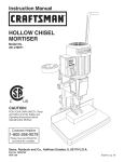
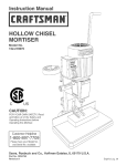
HOLLOW CHISEL MORTISER
Model No.
351.219061
CAUTION:
Read and follow
all Safety Rules and Operating
Instructions before First Use
of this Product.
Sears, Roebuck and Co., Hoffman
www.sears.com/craftsman
15140.03 Draft (08/30/02)
Estates, IL 60179 U.S.A.
PREPARE
Warranty..................................
SafetyRules..............................
Unpacking
.................................
Assembly
................................
Installation
...............................
Operation
................................
Maintenance.............................
PartsIllustration
andList ..................
Espa5ol...............................
2
2-3
3
3-5
5-6
6-8
8-9
10-11
12-19
WORK
AREA FOR JOB
•
Keep work area clean. Cluttered work areas invite
accidents.
•
Do not use power tools in dangerous environments.
•
Do not use power tools in damp or wet locations. Do
not expose power tools to rain.
•
Work area should be properly lighted.
•
Proper electrical receptacle should be available for
tool. Three prong plug should be plugged directly
into properly grounded, three-prong receptacle.
•
Extension cords should have a grounding prong and
the three wires of the extension cord should be of
the correct gauge.
FULL ONE YEAR WARRANTY
If this product fails due to a defect in material or workmanship within one year from the date of purchase,
Sears will at its option repair or replace it free of
charge. Contact your nearest Sears Service Center (1800-4-MY-HOME) to arrange for product repair, or
return this product to place of purchase for replacement.
•
Keep visitors at a safe distance from work area.
•
Keep children out of workplace. Make workshop childproof. Use padlocks, master switches or remove switch
keys to prevent any unintentional use of power tools.
TOOL SHOULD
If this product is used for commercial or rental purposes, this warranty will apply for 90 days from the date of
purchase.
This warranty applies only while this product is used in
the United States.
This warranty gives you specific legal rights and you
may also have other rights which vary from state to
state.
•
Always unplug tool prior to inspection.
•
Consult manual for specific maintaining and adjusting procedures.
•
Keep tool lubricated and clean for safest operation.
•
Remove adjusting tools. Form habit of checking to
see that adjusting tools are removed before switching machine on.
•
Keep all parts in working order. Check to determine
that the guard or other parts will operate properly
and perform their intended function.
•
Check for damaged parts. Check for alignment of
moving parts, binding, breakage, mounting and any
other condition that may affect a tool's operation.
•
A guard or other part that is damaged should be
properly repaired or replaced. Do not perform
makeshift repairs. (Use parts list provided to order
replacement parts.)
Sears, Roebuck and Co., Dept. 817WA, Hoffman
Estates, IL 60179
WARNING:
For your own safety, read all of the rules
and precautions before operating tool.
KNOW HOW TO USE TOOL
CAUTION: Always follow proper operating procedures
as defined in this manual even if you are familiar with
use of this or similar tools. Remember that being careless for even a fraction of a second can result in severe
personal injury.
BE PREPARED
•
•
Use right tool for job. Do not force tool or attachment
to do a job for which it was not designed.
•
Disconnect tool when changing blades.
•
Avoid accidental start-up. Make sure that the switch
is in the OFF position before plugging in.
•
Do not force tool. It will work most efficiently at the
rate for which it was designed.
•
Keep hands away from moving parts and cutting
surfaces.
•
Never leave tool running unattended. Turn the power
off and do not leave tool until it comes to a complete
stop.
•
Do not overreach. Keep proper footing and balance.
•
Never stand on tool. Serious injury could occur if tool is
tipped or if blade is unintentionally contacted.
•
Know your tool. Learn the tool's operation, application and specific limitations.
FOR JOB
Wear proper apparel. Do not wear loose clothing,
gloves, neckties, rings, bracelets or other jewelry
which may get caught in moving parts of machine.
•
Wear protective hair covering to contain long hair.
•
Wear safety shoes with non-slip soles.
•
Wear safety glasses complying with United States
ANSI Z87.1. Everyday glasses have only impact
resistant lenses. They are NOT safety glasses.
•
Wear face mask or dust mask if operation is dusty.
•
Be alert and think clearly. Never operate power tools
when tired, intoxicated or when taking medications
that cause drowsiness.
BE MAINTAINED
© Sears, Roebuck and Co,
2
•
Use recommended accessories (refer to page 11).
Use of improper accessories may cause risk of
injury to persons.
•
Handle workpiece correctly. Protect hands from possible injury.
•
Refer to Figures 2 - 11.
INSTALLING
Turn machine off if it jams.
THE ELEVATION
HANDLE
•
CAUTION: Think safety! Safety is a combination of
operator common sense and alertness at all times
when tool is being used.
Position the handle with coupling on to the shaft coupling so that the teeth on the couplings mesh properly.
•
Different teeth-mesh combinations provide different
leverage.
WARNING:
Do not attempt to operate tool until it is
completely assembled according to the instructions.
•
•
Position the handle for the desired leverage.
Secure handle to shaft coupling using spring and
shoulder screw.
•
Use a 12mm open end or an adjustable wrench to
tighten the handle: there are two flats ground on the
handle shaft, near the threads.
Refer to Figure 1 below.
Check for shipping damage. If damage has occurred, a
claim must be filed with carrier. Check for completeness. Immediately report missing parts to dealer.
The hollow chisel mortiser is shipped complete in one
carton. Additional parts which need to be fastened to
mortising machine should be located and accounted for
before assembling.
A Mortising Machine
B Fence
C
D
E
F
Cylinder
Handle with Coupling
Table
Holder
G
H
Chuck Key
Handle
I
J
K
L
M
N
Adaptor
Spring
Shoulder Screw
Rod
Hold-down
Wrench
Figure 2 - Install Handle
INSTALLING
THE HYDRAULIC
CYLINDER
•
Determine top from bottom of hydraulic cylinder. The
large diameter section goes on the top.
•
Snap the bottom fitting on its post.
3/8"Mortising Chisel and Bit Set (not shown)
Hardware Bag (not shown):
8-1.25 x 8mm Set Screw(2)
6-1.0 x 35mm Socket Flat Head Screw (2)
T-nuts (2)
Figure 3 - Install Cylinder Bottom
•
Use the handle to raise the head in order to snap
the top fitting on its shaped post.
E
Figure 4 - Install Cylinder Top
•
Figure 1 - Unpacking
3
When both ends are snapped in place, check
security with a slight tug.
H
•
INSTALLING
HOLDER
Check the movement of the head, and its return,
using the handle.
INSTALLING
THE TOOL AND CHISEL
Slide the tool and chisel holder into the vertical slots
towards the back of the mortiser shaft.
THE TABLE
Place the two flat head screws in the top side of the
table, and attach the T-nuts loosely underneath.
Figure 8 - Install Chisel Holder
INSTALLING
BIT AND CHISEL
Figure 5 - Attach T-Nuts
Bit and chisel come boxed together, with the bit inside
the chisel.
•
Insert the nuts into the slots in the base of the
mortiser.
Always make sure the mortiser is disconnected from its
power source before starting to install the set.
Tighten the screws firmly, but not too tight.
•
Always place the chip escape slot in the chisel shaft
to one side, right or left, never to front or rear.
Handle chisels with care: they are exceptionally
sharp. A small block of wood is a help to hold the
chisel in place while the procedure goes on.
•
Open the chuck access doors.
•
Open the chuck as far as needed: check by removing the chisel from its drill, and using the drill shank
to size the chuck opening.
Figure 6 - Install Table
INSTALLING
HOLD-DOWN
•
THE FENCE AND
Locate the fence handle, rod and handle.
Slide the fence shaft into the hole in the
column.
Figure 9 - Chuck Access
Screw the handle into the hole on the outside of the
column designed to hold the fence shank, and tighten firmly.
Loosen the front set screw on the mortiser, and slide
the chisel as far up into the head as it will go. Now,
lower the chisel about W' and tighten the set screw.
This clearance is essential. The bit cutting lips and
the points of the chisel must have the correct clearance; this distance provides that clearance.
Slip the rod into the hole on the fence. Turn the shaft
so its flat side faces the threaded hole in the fence.
Figure 7 - Install Hold-down
• Insert the set screw and secure rod to fence.
•
Figure 10 - Chisel Bushing
Slip the hold down on to the rod. Insert set screw
and secure hold-down to rod.
4
•
•
POWER
Push the bit as far up through the chisel as it will go
into the open chuck. Lock the bit in the chuck using
the chuck key. The bit point should be very sharp:
use the block of wood used to insert the bit as a
pusher.
WARNING:
The motor is designed for operation on the voltage and
frequency specified. Normal loads will be handled safely on voltages not more than 10% above or below specified voltage. Running the unit on voltages which are not
within range may cause overheating and motor burnout. Heavy loads require that voltage at motor terminals
be no less than the voltage specified on nameplate.
NOTE: Hollow chisel mortiser is supplied with an adaptor to accept short shank drill bits. To install adaptor:
• Make sure the morfiser is turned off and disconnected from the power source.
.
Open the access windows from both sides of the
mortiser head.
•
Hold the motor shaft by the flats through the access
window. Use the wrench supplied.
•
Through the other access window, insert chuck key
into the hole on the outside of the chuck.
•
Turn the chuck key counterclockwise
the motor shaft.
•
Loosen and remove chuck.
•
Install adaptor onto motor shaft using the threaded
hole. Tighten adaptor.
•
Do not connect hollow chisel mortiser to
the power source until all assembly steps have been
completed.
Loosen the front set screw and move chisel up to
head. The proper clearance between bit and chisel is
now set.
•
SOURCE
Power supply to the motor is controlled by a rocker
switch. Removing the key from rocker switch will lock
the unit and prevent unauthorized use.
GROUNDING
INSTRUCTIONS
WARNING:
Improper connection of equipment
grounding conductor can result in the risk of electrical
shock. Equipment should be grounded while in use to
protect operator from electrical shock.
while holding
.
Check with a qualified electrician if you do not understand grounding instructions or if you are in doubt as
to whether the tool is properly grounded.
.
This tool is equipped with an approved cord rated at
150V and a 3-prong grounding type plug (See Figure
12) for your protection against shock hazards.
Install chuck onto adaptor using the threaded hole.
Tighten chuck.
o Grounding plug should be plugged directly into a
properly installed and grounded 3-prong groundingtype receptacle, as shown (See Figure 12).
Grounded Outlet
Grounding Prong
3-Prong Plug
Properly
Figure 12 - 3-Prong Receptacle
Figure 11 - Tighten Chuck
°
The hollow chisel mortiser weighs approximately 50 Ibs.
when completely assembled. The hollow chisel mortiser
must be installed in a place with ample lighting and correct power supply. To install hollow chisel mortiser:
.
.
.
.
__
Do not remove or alter grounding prong in any manner.
In the event of a malfunction or breakdown, grounding
provides a path of least resistance for electrical shock.
WARNING:
Do not permit fingers to touch the terminals of plug when installing or removing from outlet.
Make sure there is plenty of room for moving the
workpiece through the entire cut. There must be
enough room that neither the operators nor the
bystanders will have to stand in line with the wood
while using the tool.
Use this tool only after fastening it to the bench: the
long handle gives needed leverage for mortising, but
also pulls the machine forward and over.
Insert two lag 5/16"x 2" screws (not supplied), with flat
washers, through the holes in the base, and drive
them into the benchtop, after drilling pilot holes.
If the mortiser is to be left portable, attach it to a 3/4"
x 13" wide x 16" long plywood base (not supplied)
that can be clamped or bolted to the benchtop.
5
•
Plug must be plugged into matching outlet that is
properly installed and grounded in accordance with
all local codes and ordinances. Do not modify plug
provided. If it will not fit in outlet, have proper outlet
installed by a qualified electrician.
•
Inspect tool cords periodically, and if damaged, have
repaired by an authorized service facility.
•
Green (or green
grounding wire.
tric cord or plug
green (or green
•
A 2-prong wall receptacle must be replaced with a
properly grounded 3-prong receptacle installed in
accordance with National Electric Code and local
codes and ordinances.
and yellow) conductor in cord is the
If repair or replacement of the elecis necessary, do not connect the
and yellow) wire to a live terminal.
Hertz ....................................
WARNING:
Any receptacle replacement should be
performed by a qualified electrician.
Phase ................................
RPM ..................................
A temporary 3-prong to 2-prong grounding adapter
(See Figure 13) is available for connecting plugs to a
two pole outlet if it is properly grounded.
Make Sure This
Grounding Lug _
Is Connected
3-Prong Plug
ELECTRICAL
60
Single
1725
CONNECTIONS
WARNING:
Make sure unit is turned off and disconnected from power source before inspecting any wiring.
To A Known
Ground
ON-OFF
SWITCH
The operating positions of the ON-OFF switch are
located on the front of your mortiser.
Push the switch up to turn mortiser On and push
down to turn the unit Off.
2-Prong Receptacle
Figure 13 - 2-Prong Receptacle with Adapter
•
The switch has a removable key that allows the unit
to be locked in the OFF position.
Do not use a 3-prong to 2-prong grounding adapter
unless permitted by local and national codes and
ordinances. (A 3-prong to 2-prong grounding adapter
is not permitted in Canada.)
To activate locking mechanism:
Push the switch to OFF position.
Pull switch key.
Where a 3-prong to 2-prong grounding adapter is
permitted, the rigid green tab or terminal on the side
of the adapter must be securely connected to a
permanent electrical ground such as a properly
grounded water pipe, a properly grounded outlet box
or a properly grounded wire system.
To deactivate locking mechanism:
insert and press switch key in the slot on switch.
Many cover plate screws, water pipes and outlet
boxes are not properly grounded. To ensure proper
ground, grounding means must be tested by a qualified electrician.
EXTENSION
•
•
CORDS
Figure 14 - On-Off Switch
The use of any extension cord will cause some drop
in voltage and loss of power.
Wires of the extension cord must be of sufficient size
WARNING:
Be sure the switch is in OFF position and
the cord is unplugged from the power source before
removing switch key.
to carry the current and maintain adequate voltage.
• Use the table to determine the minimum wire size
(A.W.G.) extension cord.
•
The motor is assembled with an approved three conductor cord to be used on 120 volts as indicated. The
power supply to the motor is controlled by a double
pole locking rocker switch.
Use only 3-wire extension cords having 3-prong
grounding type plugs and 3-pole receptacles which
accept the tool plug.
Remove the key to prevent unauthorized use.
The power lines are inserted directly onto the switch.
The green ground line must remain securely fastened
to the frame to properly protect against electrical shock.
If the extension cord is worn, cut or damaged in any
way, replace it immediately.
EXTENSION CORD LENGTH
Wire Size
A.W.G.
Up to 50 ft ................................
50-100 ft ..................................
16
14
DESCRIPTION
NOTE: Using extension cords over 100 ft. long is not
recommended.
The Craftsman hollow chisel mortiser is a heaw duty,
portable, machine designed to produce mortises up to
_/2"wide in hardwoods and 3/4"wide in softwoods. Slow
MOTOR
feeds and patience allow the user to create 3/4"wide
mortises in most hardwoods. The Craftsman mortiser is
Mortising machine is supplied with a 1/_HP (max developed) motor.
powered by a 120 volt, 4.0 amps, 60 Hz electric motor.
The mortiser uses hollow chisel mortising tools. While
the Craftsman mortiser is designed for portability, it
should never be used without secure fastening to a
solid bench or other surface to prevent tipping.
The 120 Volt AC universal motor has the following
specifications:
Horsepower (Maximum Developed) ..............
1/_
Voltage .................................
120
Amperes
4.0
................................
6
SPECIFICATIONS
Chisel capacity ........................
1/4"to 3/4"
Turn switch off and disconnect power whenever
mortiser is not in use.
Maximum height of work under head,
with W' chisel and bit in place; normal
base position (not reversed): .................
Vertical Stroke of head .....................
4W'
45/8"
Fence to center of chisel maximum distance: .....
3W'
Chuck capacity ............................
Weight ................................
OPERATION
SAFETY
on medications that affect your emotional or physical
stability.
Keep mortiser maintained. Follow maintenance
instructions (see page 9).
OPERATING
3/8"
THE HEAD
The head is moved with the handle. The lever is long
enough to give a great deal of leverage: make sure
the machine is clamped or bolted to the bench or
other stable surface.
67 Ibs
RULES
WARNING:
Operation of any power tool can result in
foreign objects being thrown into eyes which can result
in severe eye damage. Always wear safety goggles
complying with United States ANSi Z87.1 (shown on
package) before commencing power tool operation.
Use the depth stop rod to adjust the depth of the mortise. The rod has has a set screw to hold it at the depth
needed. The flat side on the depth stop rod gives good
surface for the set screw. Loosen the set screw.
WARNING:
For your own safety, read all of the
instructions and safety precautions before operating
tool.
•
Know general power tool safety. Make sure all precautions are understood (see pages 2, 3, 5 and 6).
•
Whenever adjusting or replacing any parts on morriser, turn switch off and remove plug from power
source.
•
Make sure all moving parts are free from interference.
•
Always wear eye protection or face shield.
Figure 15-
Do not plug in mortiser unless switch is in OFF position. After turning switch on, allow morfiser to come
to full speed before operating.
Move the chisel down to the desired depth (mark the
depth on a piece of scrap wood and bring the chisel
down to that mark).
Keep hands clear of all moving parts.
Hold the chisel at that mark, and slide the depth stop
rod down. Tighten the set screw.
Use the mortiser only for mortising hard and soft
woods.
•
Adjust Depth Stop
•
Make sure workpieces are free of foreign objects
such as nails, screws, staples, etc.
ADJUSTING
•
Secure workpiece under holddown to prevent it from
lifting.
•
Support workpiece against fence to prevent it from
spinning.
•
Make sure the machine is securely mounted on its
bench, or on a plywood mounting plate that may be
clamped to a bench or other work surface.
Keep lightly lubricated as directed.
Make sure all included covers are in place and
secured before operating the mortiser.
DOWN ADJUSTMENT
The hold-down keeps the workpiece from lifting as the
chisel and bit set is backed out of the mortise. Adjust
the hold-down so it just touches the top of the workpiece, while allowing the workpiece to slide right and
left without hindrance.
Disconnect power when changing bits and chisels.
•
The fence slides in and out after the knob is loosened
HOLD
Make sure drills and chisels are sharp.
Always keep hands and fingers clear of the
descending head and the turning bit.
THE FENCE
Again use scrap stock of the correct size to align the
fence. Always check alignments before working in
good stock.
Make sure drill bit chisel is properly secured.
•
Operate without power to check, and re-set if needed.
Clear blockages only after disconnecting power.
•
Do not leave the morfiser running when it is unattended.
•
Keep children away from the mortiser at all times.
•
Do not operate the mortiser when you are tired, ill or
Figure 16 - Adjust Hold Down
7
Placing the hold-down on its shaft upside down
gives another %" clearance for thicker stock, but the
hold-down set screw does not then hit the flat on the
hold-down shaft, so the hold-down may not be as
secure as needed unless special care is taken in
tightening the set screw.
•
Remove the handle.
•
Lie the machine on its back and remove both hex
nuts, washers and socket head bolts.
•
Reverse the base and reinstall the socket head
bolts, washers and hex nuts.
•
Stand the mortiser upright, and clamp the base to
the bench or table. Make sure it is very securely
clamped as the entire weight of the mortising head
is now off the bench.
•
Reinstall the handle.
Figure 17 - Adjust Chisel
CHISEL
ADJUSTMENT
The Chisel must be adjusted parallel to the workpiece's
side for standard mortising.
•
•
•
•
Place a piece of stock of the correct size in the holddown, against the fence.
Loosen the set screw on the chisel shank.
•
Turn the chisel until its back surface is flat to the
workpiece.
Install the fence and hold-down, if those have been
removed.
•
Follow earlier procedures for alignment and cutting.
Figure 18-
Reverse Setup
Tighten the set screw.
MORTISING
OPERATION
•
Select a sharp chisel of the size needed for the mortise, and install it as described earlier in this manual.
•
•
Next, set the depth.
To move the work to the left to continue the mortise
WARNING: Turn the switch to OFF position and
unplug mortiser from power source before proceeding
to do maintenance work.
GENERAL
MAINTENANCE
length, set the chisel opening to the left. To move
work to the right, set the chisel opening to the right.
This helps keep chips form obscuring the work area.
Mortiser will operate best if it is kept in good operating
condition. Keep unit adjusted as described in
"Operation."
•
Adjust the hold-down securely.
•
•
Keep a steady, firm hand on the lever and feed the
bit and chisel into the workpiece as fast as the workpiece accepts the feed without the mortiser motor
stalling. Too slow a speed may burn the bit tip.
Do not allow gum and pitch to accumulate on the
tables, fence, blades and blade guard.
•
Apply a thin coat of paste type wax to the tables and
the fence so that the wood slides easily while feeding.
•
Do not allow chips to accumulate on the underside
of the Mortiser.
•
•
Light smoke is a normal part of the operation with
some woods, as resins burn off, and chip friction creates heat. A blued chisel is not a sign of dullness, but
of chip friction heat and resin build-up.
The chisel is too dull when a lot of force is needed to
ADJUSTING
THE HEAD-TO-COLUMN
FIT
A dovetail gib fits into a dovetail way on the mortiser
shaft. On the right side-facing the machine from its
operating position-there are two allen head set screws
with nuts. Inside the dovetail gib, those screws bear on
a steel plate that rides on the dovetail way. This assembly provides an adjustment for wear that comes with
use.
continue working easily. Tip: For through mortises,
use a sacrificial backer board to prevent chip out and
table damage.
MORTISING
INTO THE ENDS OF LONG (OR
SIDES OF THICK) PIECES
Often, mortises are needed in taller pieces than can fit
under the hold-down when the base is used. In such
cases, rotating the mortiser on its base can be done.
• Removed the tool holder and tools.
8
•
Loosen the lock nuts.
•
Adjust upper and lower Allen screws until the gib
moves easily, but not sloppily, on the way. The fit
should be snug, but the movement must also be
easy. No side to side slop should be evident.
Figure 19 - Adjust Gib
+ Tighten the lock nuts and check the movement
again.
9
Model 351.219061
Figure 20 - Replacement
Parts Illustration
49
for Mortising
51
17
14
37
41
53
.J
45
44
29
28
27
10
Machine
KEY
NO.
PART NO.
DESCRiPTiON
15850.00
17300.00
00483.00
Tool Holder
Column
8-1.25 x 25mm Socket
Head Bolt
1
1
3
4
5
6
7
8
9
10
11
12
13
14
15
16
17
15888.00
08066.00
15889.00
17301.00
00958.00
15854.00
15855.00
17302.00
15886.00
STD852008
15887.00
15857.00
17303.00
04417.00
Capacitor
Switch
Switch Box
Handle
8-1.25 x 8mm Set Screw
Hold-Down
Rod
Fence
1
1
1
1
2
1
1
1
Depth Stop Rod
8mm Lock Washer*
Motor
Trout
Base
4-0.7 x 6mm Socket Pan
Head Screw
1
3
1
2
1
2
18
19
15884.00
15860.00
2
2
2O
21
17304.00
15862.00
6 x 28mm Spring Pin
6-1.0 x 35mm Socket Flat
Head Screw
Table
10 x 35ram Socket Head
Shoulder Screw
22
23
24
15863.00
17402.00
15865.00
15866.01
15070.00
17403.00
15868.00
15869.00
Spring
Handle Coupling
Handle
1
1
1
Grip
Adaptor
Shaft Coupling
Shaft
Collar
1
1
1
1
1
1
2
3
25
26
27
28
29
KEY
NO.
QTY.
PART NO.
DESCRiPTiON
32
33
07322.00
15870.00
01210.00
16846.00
34
01775.00
35
36
37
15871.00
15872.00
06701.00
38
39
4O
41
42
43
44
45
46
47
16847.00
15874.01
15875.01
01474.00
15877.01
15878.00
05110.00
STD840610
08560.00
01505.00
5x5x12mmKey
Gear
5-0.8 x 5mm Set Screw
8-1.25 x 20mm Brass Flat
Point Set Screw
6-1.0 x 25mm Socket
Head Bolt
Cover
Plate
5-0.8 x 8mm Socket Pan
Head Screw
Knob
48
49
50
51
52
53
54
55
A
A
A
15879.00
01601.00
16426.00
15882.00
15883.00
00935.00
15885.00
18967.00
26413
26417
15140.03
30
31
1
1
* Standard hardware item available locally.
A Not Shown
Recommended
11
QTY.
1
1
1
1
4
2
2
6
2
Chuck Key
Chuck with Key
5mm Serrated Washer
Head
1
1
1
1
Bushing
6-1.0 x 20mm Set Screw
6-1.0mm Hex Nut*
8-1.25 x 16ram Set Screw
6-1.0 x 12mm Socket
Head Bolt
Rack
Strain Relief
Plate
Ball Head Screw
1
2
4
1
2
Hydraulic Cylinder
Line Cord
Gib
Wrench
1
1
1
1
Mortising Bit 3/8"
Mortising Chisel 8/_,,
Owner's Manual
1
1
1
1
1
2
2
Accessories
A
Mortising Bit 1/4"
9-26411
A
Mortising Bit 8/1U'
9-26412
A
Mortising Bit W'
9-26414
A
Mortising Chisel 1/4"
9-26415
A
Mortising Chisel 8/16"
9-26416
A
Mortising Chiset 1/t"
9-26418
IVIORTAJADORA DE FORIVION
HUECO
•
Use zapatos
•
Use galas de seguridad que cumplan con ANSI Z87.1 de los
Estados Unidos. Los espejuelos para uso diario s61o tienen
lentes resistentes al impacto. NO son galas de seguridad.
Modelo No.
•
Use una mascara para la cara o contra
operaci6n es polvorosa.
351.219061
•
PRECAUCION:
Lea y siga todas las Reglas
de Seguridad y las Instrucciones
de Operaci6n
antes de usar este producto por primera vez.
Est6 alerta y piense claramente. Nunca opere las herramientas mecanicas cuando est6 cansado, intoxicado o cuando
est6 tomando medicamentos
que producen somnolencia.
PREPARE
Ingles
.......................................
Ilustraci6n
Garantia
Reglas
y Lista
10-11
......................................
de Seguridad
Desempaque
Montaje
12
..........................
......................................
15
..................................
15-17
Operaci6n
..................................
17-18
Mantenimiento
...............................
GARANTIA
COMPLETA
Si fallara este producto
por causa
18-19
No use herramientas
mecanicas
en entornos
•
No use herramientas
dos. No las exponga
mecanicas
a la Iluvia.
en lugares
•
El Area de trabajo
correcta.
•
Tiene que haber un receptaculo electrico correcto disponible
para la herramienta.
El enchufe de tres puntas se debe enchufar directamente
en un receptaculo para tres puntas, conectado a tierra correctamente.
•
Los cordones de extensi6n deben tener una punta para la
conexi6n a tierra y los tres cables del cord6n de extensi6n
tienen que ser del calibre correcto.
•
Mantenga
trabajo.
•
Mantenga a los niSos fuera del lugar de trabajo. Haga que
el taller sea a prueba de niSos. Use candados, interruptores
principales o remueva las Ilaves de los interruptores
para
evitar el uso no intencional de las herramientas
mecanicas.
DE UN AI_IO
de defectos
alas
de-
peligrosos.
hQmedos
o moja-
tiene que contar con una iluminaci6n
visitas a una distancia
ES NECESARIO
en el material
PARA LA TAREA
•
15
Instalaci6n
DE TRABAJO
el polvo si la
Mantenga el Area de trabajo limpia. Las Areas de trabajo
sordenadas atraen accidentes.
12-13
..................................
EL AREA
con suelas antideslizantes.
•
2-9
de Partes .....................
de seguridad
MANTENER
segura
del Area de
LAS HERRAMIENTAS
en la mano de obra en un lapso de un aSo a partir de la
•
Siempre
fecha de compra, Sears Io reparara o reemplazar&
a su
elecci6n, sin costo adicional. Solicite al Centro de servicio
Sears (1-800-MY-HOME)
mas cercano la reparaci6n del
•
Consulte el manual para ver los procedimientos
de mantenimiento
y ajuste.
•
Mantenga
operaci6n
•
Remueva las herramientas
de ajuste. Adquiera el habito de
revisar para verificar si se han removido las herramientas
de ajuste antes de encender la maquina.
•
Mantenga todas las partes listas para trabajar. Inspeccione
la
herramienta
para verificar si los dispositivos de protecci6n o
si las demas partes pueden operar correctamente
y desempeSar la funci6n para la que han sido diseSadas.
•
Revise para verificar si hay partes daSadas. Revise el alineamiento de las partes movibles, verifique si su movimiento se
halla restringido, si estan rotas, si se sobremontan
o si existe
alguna otra condici6n que pueda afectar la operaci6n de la
herramienta.
•
Es necesario cambiar o reparar correctamente
un mecanismo
de protecci6n u otra parte que est6 daSada. No haga reparaciones provisorias. (Use la lista de partes que se ofrece para
encargar las partes de repuesto.)
producto
o devuelvalo
al establecimiento
donde
Io adquiri6.
Si este producto se usa para fines comerciales
o de alquiler,
esta garantia es valida por 90 dias a partir de la fecha de
compra.
Esta garantia aplica L_nicamente cuando
en los Estados Unidos.
el producto
se utiliza
Esta garantia le otorga derechos legales especMcos y
tambien puede usted tener otros derechos que varien de
estado a estado.
Sears, Roebuck
IL 60179
and Co., Dept. 817WA,
Hoffman
ADVERTENClA:
Para su propia seguridad,
y las precauciones
antes de operar la herramienta.
PRECAUClON:
Siempre
lea todas las reglas
siga los procedimientos
correctos, tal como se definen en este manual,
familiarizado
con esta o con otras herramientas
•
Use la ropa adecuada.
No use ropa suelta,
Use una cubierta
tener, el cabello
de protecci6n
para el cabello,
lubricada
especificos
y limpia para Iograr una
Use la herramienta correcta para el trabajo. No fuerce la herramienta ni el accesorio para hacer un trabajo para el que no
han sido diseSados.
•
Desconecte
•
Evite que arranque
est6 en la posici6n
corbatas,
engancharse
la herramienta
mas segura.
antes de inspeccionarla.
•
de segundo,
guantes,
la herramienta
APRENDA COMO USAR LA HERRAMIENTA
PARA EL TRABAJO
anillos, pulseras, ni otras joyas que puedan
partes m6viles de la maquina.
•
de operaci6n
aun cuando est6
parecidas. Re-
cuerde que, si se descuida por siquiera una fracci6n
puede sufrir lesiones personales graves.
PREPARESE
Estates,
desenchufe
alas
•
para con-
•
12
cuando
cambie
las cuchillas.
por accidente. AsegQrese que el interruptor
OFF (apagado) antes de enchufarla.
No fuerce la herramienta.
velocidad
largo.
la herramienta
Funciona
mas eficientemente
a la
para la que rue diseSada.
Mantenga las manos alejadas
superficies cortadoras.
de las partes
movibles
y de las
•
Nunca deje la herramienta
desatendida
nando. Apague la energia electrica
hasta que pare completamente.
•
No trate de alcanzar
y el equilibrio
•
cuando
m_.s de Io posible. Mantenga
con la cuchilla
pot accidente.
Conozca su herramienta. Aprenda
y sus limitaciones especificas.
su operaci6n,
•
Use los accesorios
(refierase
recomendados
Si se usan los accesorios
incorrectos
cotter el riesgo de lesionarse.
Maneje
la pieza de trabajo
manos contra posibles
a la pb.gina 13).
las personas
correctamente.
pueden
Protejase
las
Apague la mb,quina si se atasca. La cuchilla se atasca si se
introduce dentro de la pieza de trabajo a mucha profundidad.
atascada
Figura 1 - Desempaque
en el trabajo.)
Siempre mantenga la protecci6n del mecanismo de accionamiento, del portacuchillas
y de la cuchilla en su lugar,
yen
•
su aplicaci6n
lesiones.
(La fuerza del motor la mantiene
•
E
Nunca se pare sobre la herramienta.
Se pueden producir
lesiones graves si la herramienta
se inclina o si usted entra
en contacto
•
la posici6n
correctos.
•
•
este funcio-
y no deje la herramienta
condiciones
para operar correctamente.
Alimente el trabajo dentro de la cuchilla
en contra de la direcci6n de rotaci6n.
PRECAUCION:
iPiense
en la seguridad!
o del portacuchillas
La seguridad
Consulte
INSTALACION DE LA MANIVELA DE ELEVACION
es una
combinaci6n
del sentido comQn del operador y de estar alerta en
todo momento cuando se est,. usando la herramienta.
ADVERTENOIA:
No trate de operar la herramienta
este completamente
V6ase
montada
•
Coloque la manivela con acoplamiento
en el acoplamiento del
eje de manera que los dientes en los acoplamientos
engranen
adecuadamente
•
Diferentes combinaciones
nan diferentes potencias
•
Coloque
•
Asegure
hasta que
segQn las instrucciones.
resorte
la figura 1 a continuaci6n.
•
Verifique que no hayan ocurrido daSos durante el envio. Si hay
daSos, se deber_, presentar un reclamo a la compaSia de transporte. Verifique que est6 completa.
tribuidor si faltan partes.
La mortajadora
de form6n
las figuras 2-11.
Avise inmediatamente
hueco se envia completa
al dis-
la manivela
la manivela
y el tornillo
de engranes
para la potencia
en el acoplamiento
de dientes
proporcio
deseada
del eje usando
el
de tope
Use una Ilave de extremo
abierto
ajustable
para apretar la manivela:
tificados
en el eje de la manivela
de 12 mm o una Ilave
hay dos puntos pianos
rec
cerca de las roscas
en una caja.
Es necesario Iocalizar y tomar en cuenta las partes adicionales
que deben asegurarse a la herramienta antes de armarla:
A
Mortajadora
B
Reborde
C
Cilindro
D
Manivela
E
Mesa
F
Sujetador
G
CuSa del portabroca
H
Manivela
INSTALACION DEL CILINDRO HIDRAULICO
I
Adaptador
•
J
Resorte
Determine cu_l es la parte superior e inferior del cilindro
secci6n cuyo di_metro es mayor ira en la parte superior
K
Tornillo
•
Enganche
L
Varilla
M
Sujetador
N
Llave
con acoplamiento
Figura 2 - Instale la manivela
de tope
%" Juego de Mortajadora
Bolso de articulos
Tornillo
Tornillo
de Form6n y Barrena
de ferreteria
el acoplamiento
inferior
en su soporte
(no se muestra)
(no se muestra):
de fijaci6n de 8-1.25 x 8 mm (2)
de cabeza plana hueca de 6-1.0 x 35 mm (2)
Tuercas T (2)
Figura 3 - Instale
13
la parte inferior del cilindro
La
•
Use la manivela
acoplamiento
para elevar el cabezal
superior
en su soporte
a fin de engachar
el
conformado.
Figura 7 - Instale el sujetador
Figura 4 - Instale la parte inferior del cilindro
•
Cuando ambos extremos enganchen en su posici6n, verifique
que hayan quedado asegurados
d_.ndoles un peque_o tir6n.
•
Verifique el movimiento
manivela.
del cabezal,
y su retorno,
usando
Inserte el tornillo
•
Deslice el sujetador en la varilla. Inserte
y asegure el sujetador a la varilla.
•
de
Deslice
verticales
Figura
5 - Inserte
las tuercas
•
Inserte las tuercas
•
Apriete
la herramienta
8 - Instale el soporte
el tornillo
de fijaci6n
AsegQrese
en las ranuras
del formbn
siempre
se envian
en una misma
de que la mortajadora
la fuente de alimentaci6n
•
del form6n
del eje de la mortajadora.
DE LA BARRENA Y EL FORMON
La barrena y el form6n
dentro del form6n.
pero no demasiado.
y el soporte
hacia la parte posterior
INSTALACION
T
en las ranuras de la base de la mortajadora.
bien los tornillos,
la varilla al reborde.
INSTALACION DE LA HERRAMIENTA Y EL
SOPORTE DEL FORMON
Coloque dos tornillos de cabeza plana en el lado superior
la mesa, e inserte debajo las tuercas T sin apretarlas.
Figura
de fijaci6n y asegure
la
INSTALACION DE LA MESA
•
•
caja; la barrena
este desconectada
antes de comenzar
a instalar
de
el juego.
Coloque siempre la ranura de escape de virutas en el eje del
form6n, ya sea en el lado izquierdo o derecho, pero nunca en
la parte frontal o posterior. Maneje los formones con cuidado:
los mismos son sumamente afilados. Use un bloque de
madera para ayudar a mantener el form6n
mientras se Ileva a cabo el procedimiento.
•
Abra las puertas
•
Abra el portabroca
de acceso al portabroca.
tanto como necesite:
form6n de su barreno, y usando
medir la abertura del portabroca.
Figura 6 - Instale la mesa
INSTALACION
DEL REBORDE Y EL SUJETADOR
•
Ubique la manivela
•
Deslice
•
Atornille
Deslice
la varilla y la manivela.
el eje del reborde en el orificio
la manivela
columna dise_ado
apdete bien.
•
del reborde,
de la columna.
en el orificio de la parte exterior
para sostener
la varilla en el orificio
de la
el v_.stago del reborde,
del reborde.
manera que el lado piano quede orientado
roscado en el reborde.
y
Gire el v_.stago de
Figura 9 - Acceso al portabroca
hacia el orificio
14
en su posici6n
revise retirando
el v_.stago del barreno
el
para
Afloje el tornillo
de fijaci6n
deslice el form6n
Ahora, descienda
anterior
en la mortajadora,
y
una fuente de alimentaci6n
de form6n hueco:
en el cabezal hacia arriba hasta que tope.
el form6n aproximadamente
3 mm y apriete
•
el tornillo de fijaci6n. Este espacio libre es muy importante.
Los rebordes de corte de la barrena y los puntos del form6n
debe contar con el espacio libre adecuado;
porciona dicho espacio libre.
esta distancia
adecuada.
Para instalar
la mortajadora
AsegtJrese que haya suficiente espacio para mover la pieza
de trabajo a trav6s de todo el corte. Deber_. haber suficiente
espacio de manera que ni los operadores
ni dem_.s personas
tengan que pararse en linea con la madera mientras se est6
usando la herramienta.
pro-
•
•
Use esta herramienta
el banco: la manivela
s61o despues de haberla asegurado en
larga brinda la potencia necesaria para
mortajar, pero adem_.s tira de la m_.quina hacia delante
hacia arriba.
y
Inserte dos tornillos de fijaci6n
con
de 5/16"x 2" (no incluidos),
arandelas planas, a trav6s de los orificios en la base, y atornillelos en el banco de trabajo, luego de perforar orificios pilotos.
•
Empuje
la barrena a trav6s del form6n
hacia arriba
hasta
barrena de estar bien afilada: use el bloque de madera
emple6 para insertar el form6n como refuerzo.
Afloje el tornillo
de fijaci6n
anterior
y mueva el form6n
arriba en el cabezal. El espacio libre correcto
y el form6n se encuentra ahora ajustado.
AVlSO:
La mortajadora
que pueda sujetarse
o apernarse
al banco
de trabajo.
FUENTE DE ALIMENTACION
que tope en el portabroca
abierto. BIoquee la barrena en el
portabroca usando la cuba del portabroca.
La punta de la
•
es para uso port_.til, fijela a una base de
de 19 mm x 330 mm ancho x 406 mm de
largo (no incluidos)
Figura 10 - Buje del form6n
•
Si la mortajadora
madera laminada
ADVERTENCIA:
No conecte la mortajadora
de form6n hueco a
la fuente de alimentacidn
hasta haber cumplido todos los pasos
que
del ensamblaje.
El motor ha sido diseSado para funcionar al voltaje y frecuencia
especificados.
Las cargas normales se pueden manejar sin ries-
hacia
entre la barrena
de form6n hueco inciuye un adaptador
gos dentro de un intervalo del 10% respecto al voltaje especificado. Si se hace funcionar la unidad a un voltaje fuera de este
para
trabajar con brocas de v&stago corto. Para instalar el adaptador:
intervalo, se puede recalentar y quemar el motor. Las cargas
pesadas exigen que el voltaje en los terminales del motor no sea
•
AsegQrese que la mortajadora
de la fuente de alimentaci6n.
inferior al especificado.
•
Abra las ventanas
este apagada
y desconectada
•
de acceso a ambos
lados del cabezal
de la
interruptor
mortajadora.
•
•
culante,
Sostenga el eje del motor pot los puntos pianos
ventana de acceso. Use la Ilave que se incluye.
A trav_s de la ventana
portabroca
de acceso,
inserte
en el orificio de la parte
•
Afloje y retire el portabroca.
•
Instale
roscado.
Apriete
en el eje del motor usando
alas
manillas
mediante
la unidad e impide
PARA LA CONEXION A TIERRA
a tierra del equipo,
se corre el riesgo de un electrochoque.
Si no entiende
correctamente
las instrucciones
rosca-
Esta herramienta
viene equipada
el conductor
El
se usa para prote-
de conexi6n
a tierra o duda
que la herramienta
haya quedado efectivamente
tierra, consulte un electricista calificado.
el orificio
un
bas-
el uso no autorizado.
Si no se conecta
•
el orificio
se controla
ADVERTENClA:
•
usando
se bloquea
del motor
Si se extrae la Ilave del interruptor
equipo debe estar conectado a tierra mientras
ger al operador de un electrochoque.
el adapatador.
Instale el portabroca en el adaptador
do. Apriete el portabroca.
basculante.
INSTRUCClONES
exterior del portabroca.
Gire la cuba del portabroca en sentido contrario
del reloj a la vez que sostiene el eje del motor.
el adaptador
a trav_s de la
la cuba del
•
•
La fuente de alimentacidn
puesta a
con un cable especificado
para 150 V y un enchufe de 3 espigas para conexi6n a tierra
(vea la figura 12) que Io protegen a usted de un electrochoque.
•
El enchufe
de conexi6n
mente a un z6calo
a tierra deber_, conectarse
para 3 clavijas
instalado
directa-
y conectado
Enchufe de 3 puntas
tierra
Tomacorriente
puesto
a tierra
Espiga
de __
adecuadamente
Figura
Figura 11 - Apriete el portabroca
12-
Recept_culo
debidamente
•
para 3 puntas
a tierra, tal como se muestra
No retire ni modifique
(vea la figura 12).
en forma alguna la clavija de conexi6n
a
tierra. En caso de un mal funcionamiento
o una descompostura, la conexi6n a tierra proporciona una ruta de menor resistenLa mortajadora
de form6n
hueco pesa aproximadamente
cia para la descarga
50 lb.
ADVERTENClA:
luego de ser ensamblada.
La mortajadora de form6n hueco debe
instalarse en un lugar que cuente con suficiente iluminaci6n y
Io, no permita
15
electrica.
AI conectar
o desconectar
el enchufe
por ningtJn motivo que sus dedos toquen
del z6calas clavijas.
•
El enchufe
debe conectarse
en el tomacorriente
LONGITUD
correspon-
diente que haya sido instalado y conectado a tJerra debidamente, de acuerdo con todos los c6digos y regulaciones
Hasta 50 pies
locales. No modifique el enchufe que se incluye. Si no cabe
en el tomacorrJente, solicite a un electricista profesional que
instale un tomacorriente
adecuado.
•
Un z6calo
a un terminal
para dos clavijas
z6calo para tres clavijas debidamente
instalado de acuerdo con las Normas
Electricas (National
ciones locales.
ADVERTENCIA:
Electric
50-100
pies ......................................
AVlSO:
No se recomienda
La mortajadora
m_.ximo).
induye
El motor universal
16
14
utilizar cordones
de extensi6n
Caballaje
con un
Voltaje
conectado a tierra e
para Instalaciones
un motor de 1/2 HP (desarrollado
de CA de 120 voltios tiene las siguientes
(m_.ximo desarrollado)
.......................
1/2
Frecuencia
120
.......................................
4.0
(Hz) ...................................
60
Fase .....................................
calificado
al
.........................................
Amperaje
Code) y los c6digos y regula-
S61o un electricista
de m_.s
especificaciones:
con corriente.
deber& set reemplazado
(segQn la norma A.W.G.)
....................................
MOTOR
El conductor verde (o verde y amarillo) del cable es para
conexi6n a tierra. Si es necesario reparar o reemplazar el
cable de alimentaci6n
o el enchufe, no conecte el hilo verde
(o verde y amarillo)
•
DE EXTENSION
..............
de 30 metros de largo (100 pies).
Revise peri6dicamente
los cordones de la herramienta,
si
estb_n da_ados, Ilevelos a un centro de servicio autorizado
para que los reparen.
•
DEL CORDON
TamaSo del alambre
debe cambiar
Monof_.sico
RPM ..........................................
1725
los recept_.culos.
CONEXIONES
Existe un adaptador de conexJ6n a tierra con tres clavijas para un
z6calo de dos clavijas (v6ase la figura 13); con 61 podr_, conectar
enchufes a un tomacorrientes
bipolar siempre
encuentre debidamente
conectado a tierra.
LA_ga__°dre---,._
j,tierra __ \.._"z..
y cuando
_
este se
INTERRUPTOR DE ON/OFF
(ENCENDIDO/APAGADO)
Astg_eSeefdadqUae
Enchufe de 3 pun_l
Las posiciones de operaci6n del interruptor de ON/OFF (encendido/
apagado) est_.n ubicadas en la parte frontal de su mortajadora.
una tierra conocida
•
__
_
Receptaculo
•
con adaptador
jadora
•
el interruptor
hacia arriba
y hacia abajo para apagar
a menos que este permJtinacionales y locales. (Este
no se permiten
en CanadA).
la morta-
el interruptor
Empuje
,,
Tire de la Ilave del interruptor.
•
a la posici6n
el mecanismo
Inserte y empuje
bloquear
de bloqueo:
•
Para desactivar
Si se permite el uso de un adaptador de 3 a 2 espigas con
conexi6n a tJerra, se debe conectar firmemente la lengOeta
para encender
la unidad.
El interruptor tiene una Ilave removible que permite
la unidad en la posici6n de OFF (apagado).
para enchufe
Para activar el mecanismo
No utilice este tipo de adaptadores
do pot los c6digos y regulaciones
tipo de adaptadores
Empuje
para
enchufe de 2 puntas
Figura 13 - Recept_culo
de 2 espigas
ELECTRICAS
ADVERTENCIA:
Cerci6rese de que la unidad este apagada y
desconectada
de la fuente de alimentaci6n
antes de inspeccionar
el cableado.
de OFF (apagado).
de bloqueo:
la Ilave del interruptor
en la ranura
del interruptor.
verde o terminal rigido en un lado del adaptador a una toma
de tierra permanente,
p. ej., una tuberia de agua puesta a
tierra, una caja de tomacorriente
de cables puesto a tierra.
•
Muchos
de los tornillos
puesta a tierra o un sistema
para placas de cubierta,
las tuberias
para ca_eria y las cajas de distribuci6n
no estb_n debidamente
conectados a tierra. Para garantizar que la conexi6n a tierra
es efectiva,
tierra.
un electricista
calificado
debe verificar
la toma de
CABLES DE EXTENSION
•
El uso de cualquier
tipo de cord6n de extensi6n
una caida en el voltaje y una perdida
•
Los alambres
suficiente
del cord6n
de extensi6n
para transportar
la corriente
Figura 14 - Interruptor de ON-OFF (encendido/apagado)
ocasionar_.
de potencia.
ADVERTENClA:
adecuada
y mantener
el voltaje correcto.
El motor se ensambla
•
Utilice la tabla para determinar
el tama_o m[nimo
(segOn la norma AWG) del cord6n de extensi6n.
del alambre
•
UtilJce OnJcamente cordones
que cuenten
•
AsegQrese
de extensi6n
trifilares
que el interruptor
la posici6n de OFF (apagado) y que el cord6n
antes de extraer la Ilave del interruptor.
deben tenet el tama_o
se encuentre
en
este desconectado
con un cable de tres conductores,
aproba-
do para usarse con 120 voltios como se indic& La fuente de alimentaci6n del motor est,. controlada por un interruptor basculante enclavador bipolar.
con enchufes tJpo conexi6n a tierra de tres clavijas y z6calos
tripolares que funcionen con el enchufe de la herramienta.
,,
Si el cord6n
interruptor. La linea de conexi6n a tierra verde debe permanecer
firmemente sujeta al bastidor para ofrecer la adecuada protecci6n contra un electrochoque.
cualquier
de extensi6n
forma,
est& desgastado,
reempl_.celo
roto o da_ado
Extraiga
la Ilave para evitar el uso no autorizado.
Las lineas de energ[a
en
inmediatamente.
16
electrica
se insertan
directamente
en el
DESCRIPClON
La mortajadora
de form6n hueco Craftsman es una m_.quina
port_.til de servicio pesado diseSada para producir mortajas de
hasta 1/2"de ancho en maderas duras y 3/4"de ancho en maderas
•
AsegLirese
•
Desconecte
•
Mant6ngalos
•
Mantenga
cabezal
que los barrenos
la potencia
ligeramente
siempre
y los formones
cuando
cambie
lubricados
est6n afilados.
barrenas
y formones.
segLin se indica.
las manos y los dedos alejados
en descenso
y de la barrena
del
en rotaci6n.
•
AsegLirese que todas las cubiertas se encuentren colocadas
aseguradas en su posici6n antes de operar la mortajadora.
usuario crear mortajas de 3/4"de ancho en la mayofia de
maderas duras. La mortajadora
Craftsman es alimentada
por un
motor electrico de 120 voltios, 4.0 amperios y 60 Hz. La morta-
•
Despeje
•
No deje desatendida
jadora
•
Mantenga
momento.
•
No opere la mortajadora
si est,. cansado,
tomando medicamentos
ca o emocional.
que puedan afectar su estabilidad
suaves. La alimentaci6n
lenta y la paciencia
usa herramientas
de mortajar
le permiten
de form6n
al
hueco. Aunque
la
ESPECIFICACIONES
del form6n:
..........................
•
1/4"a 3/4"
normal de base (no invertida):
del cabezal
•
.............
10.5 cm
Recorrido
vertical
Distancia
m_.xima del reborde al centro del form6n .......
....................
11.7 cm
Peso
del portabroca
...........................
3/8"
.......................................
ADVERTENCIA:
•
de todas las herramientas
mec_.nicas puede hacer que sean lanzados a los ojos cuerpos
extraSos, Io cual puede lesionarlos gravemente. Siempre use
Para su propia seguridad,
instrucciones
y las precauciones
la herramienta.
•
y desconecte
en todo
enfermo
la alimentaci6n
o si est,.
fisi-
si no se
la mortajadora.
Mantenga la mortajadora
ciones de mantenimiento
en buen estado. Siga las instruc(v6ase la p_.gina 9).
El cabezal
se mueve con la manivela.
La palanca
es Io sufi-
estable.
Use la varilla de tope de profundidad para ajustar la profundidad
de la mortaja. La varilla incluye un tornillo de fijaci6n para
tornillo de fijaci6n. Afloje el tornillo de fijaci6n.
antes de operar
Aprenda las reglas de seguridad generales para el uso de
herramientas
mec_.nicas. AsegL_rese de comprender
todas las
precauciones
(v6ase las p_.ginas 2, 3, 5 y 6).
Cuando ajuste o reemplace cualquier parte de la mortajadora,
abra el interruptor y retire el enchufe de la fuente de alimentaci6n.
•
AsegL_rese que nada obstaculice
•
Siempre
•
No enchufe la mortajadora
a menos que el interruptor
la posici6n de OFF (apagado). Despues de encender
use protecci6n
ruptor, permita
antes de usar.
ninguna
Mantenga
•
Use la mortajadora
parte movible.
para los ojos o para la car&
que la mortajadora
•
las manos alejadas
alcance
est6 en
el inter-
el tope
•
hacia abajo, hasta la profundidad
•
maderas
duras
AsegL_rese que las piezas de trabajo
extraSos tales como clavos, tornillos,
•
Asegure la pieza de trabajo
que se levante.
•
Apoye la pieza de trabajo
gire.
est6n libres de objetos
grapas, etc.
debajo del sujetador
contra el reborde
AsegL_rese que la m_.quina est6 montada
para evitar que
firmemente
el form6n
Opere sin potencia
de madera
en dicha marca y deslice
hacia abajo. Apriete
para verificar
la varilla de
el tornillo
y reajuste
deseada
de desecho
de fijaci6n.
de ser necesario.
AJUSTE DEL REBORDE
para evitar
•
El reborde se desliza
aflojar la manilla.
•
Nuevamente
hacia adentro
use el pedazo
y hacia fuera luego de
de madera de desecho
correcto para alinear el reborde. Siempre verifique
mientos antes de trabajar en madera buena.
en este
banco, o en una placa de montaje de madera laminada
pueda sujetarse al banco o a otra superficie de trabajo.
Sostenga
tope de profundidad
•
•
Mueva el form6n
de profundidad
(marque la profundidad
en un pedazo
y baje el form6n hasta dicha marca).
de las parte movible.
L_nicamente para mortajar
AsegL_rese que el form6n
Figura 15 - Ajuste
toda la velocidad
y suaves.
•
est,. en marcha.
lea todas las
de seguridad
•
•
mientras
sostenerla a la profundidad necesaria. El lado piano de la varilla
de tope de profundidad ofrece una buena superficie de agarre al
galas de seguridad que cumplan con los requisitos de la norma
estadounidense
ANSI Z87.1 (se indica en el paquete) antes de
comenzar a usar la herramienta mec_.nica.
ADVERTENClA:
el interruptor
de trabajo o a otra superficie
DE OPERACION
El funcionamiento
Apague
la mortajadora
cientemente
larga como para ofrecer la potencia necesaria:
asegL_rese que la m_.quina est6 sujeta o apernada al banco
30.2 Kg
REGLAS DE SEGURIDAD
la
OPERAClON DEL CABEZAL
9 cm
•
Capacidad
s61o despues de desconectar
a los niSos alejados de la mortajadora
est,. usando
Altura m_.xima del trabajo debajo del cabezal,
con form6n de 1/4"y barrena colocados;
posici6n
obstrucci6n
potencia.
mortajadora
Craftsman est,. diseSada para emplearse como herramienta port_.til, nunca deber_, usarse antes de ser asegurada a
un banco s61ido o a otra superficie para evitar que se incline.
Capacidad
cualquier
y
que
de brocas est6 bien afianzado.
17
del tamaSo
los alinea-
AJUSTE DEL SUJETADOR
•
•
Es normal que la operaci6n
con algunos
tipos de madera pro-
El sujetador evita que la pieza de trabajo se levante cuando el
juego de form6n y barrena se retira de la mortaja. Ajuste el
duzca un poco de humo, ya que las resinas se queman y la
fricci6n de las astillas genera calor. Un form6n azulado no es
sujetador de manera que toque la parte superior de la pieza de
trabajo, a la vez que permite que la pieza de trabajo se deslice
seSal de desgaste, si no de calor generado
las astillas y acumulaci6n de resinas.
de derecha
a izquierda
sin impedimento
•
alguno.
El form6n
estgt demasiado
desgastado
pot la fricci6n de
cuando
se necesita
una gran cantidad de fuerza para continuar trabajando sin dificultad. Consejo: Para mortajas transversales,
use un tablero
de respaldo de sacrificio
daSo a la mesa.
MORTAJADO
para evitar la producci6n
de astillas y
EN EXTREMOS DE PIEZAS LARGAS
(O LADOS DE PIEZAS GRUESAS)
A menudo,
se necesitan
mortajas
en piezas
m_.s altas que las
que caben debajo del sujetador cuando se utiliza la base. En
dichos casos, se puede girar la mortajadora
en su base.
\
Figura 16 - Ajuste el sujetador
•
Colocar
el sujetador
en su eje ofrece
adicional para material
del sujetador entonces
1.6 cm de espacio
libre
m&s grueso, pero el tornillo de fijaci6n
no hat& contacto con el punto piano
en el eje del sujetador, por Io que este quiz& no quede tan
seguro como debiera a menos que se ponga esmero en apre-
•
Retire el portaherramienta
•
Retire la manivela.
•
Acueste
la m&quina
tuercas
hexagonales,
arandelas
•
Coloque
la mortajadora
y retire ambas
y pernos de cabeza
Invierta la base y vuelva a instalar
hueca, las arandelas y las tuercas
hueca.
los pernos de cabeza
hexagonales.
de manera vertical
y sujete
la base al
banco o mesa. AsegQrese que quede firmemente sujeta ya
que todo el peso del cabezal de la mortajadora
se encuentra
fuera del banco.
•
17 - Ajuste
sobre su parte posterior
•
tar el tornillo de fijaci6n.
Figura
y las herramientas.
Vuelva a instalar
la manivela.
el formbn
AJUSTE DEL FORMON
El form6n
trabajo
debe ajustarse
para mortajadoras
de forma
•
Coloque la pieza de material
tador, contra el reborde.
•
Afloje el tornillo
•
Gire el form6n
con respecto
•
Apriete
paralela
al lado de la pieza de
Figura
de fijaci6n
del tamaSo correcto
en el suje-
en el vb,stago del form6n.
hasta que su superficie
posterior
Invierta
la instalacibn
•
Instale el reborde y el sujetador,
removidos.
•
Siga los procedimientos
si fueron anteriormente
anteriores
para alineamiento
y corte.
quede plana
a la pieza de trabajo.
el tornillo de fijaci6n.
ADVERTENClA:
OPERACION DE IV1ORTAJADO
•
18-
est_.ndar.
Seleccione un form6n afilado del tama_o necesario
mortaja e inst_.lelo segQn se describi6 anteriormente
manual.
para la
en este
•
Luego, ajuste la profundidad.
•
Para mover la pieza de trabajo hacia la izquierda a modo de
continuar el largo de la mortaja, ajuste la abertura del form6n
MANTENIMIENTO
•
ayuda a evitar que las astillas obstruyan
•
•
Mantenga un agarre firme y fijo en la palanca, y alimente la
barrena y el form6n en la pieza de trabajo tan r&pido como la
podria quemar
No permite que goma ni grumo de resina se acumulen
Aplique
una capa delgada
y la proteccidn
•
No permita
que las astillas
la mortajadora.
sin que el motor de la
demasiado
lenta
la punta de la barrena.
18
en las
de las cuchillas.
de pasta tipo cera a las mesas y al
reborde de manera que la madera
durante la alimentaci6n.
firmemente.
pieza de trabajo acepte la alimentaci6n
mortajadora
se atasque. Una velocidad
de OFF (apa-
GENERAL
mesas, el reborde, las cuchillas
el _.rea de trabajo.
Ajuste el sujetador
a la posici6n
La mortajadora
funcionar_, mejor si se mantiene en buenas
condiciones de operaci6n. Mantenga la unidad tal como se
describe en la seccidn "Operacidn".
hacia la izquierda. Para mover la pieza de trabajo hacia la
derecha, ajuste la abertura del form6n hacia la derecha. Esto
•
Lleve el interruptor
gado) y desconecte la mortajadora
de la fuente de alimentaci6n
antes de realizar labores de mantenimiento.
se deslice
se acumulen
f_.cilmente
en la parte oculta de
AJUSTE DEL ARREGLO
LA COLUMNA
ENTRE EL CABEZALY
Una cuba de cola de milano cabe dentro de una via de cola de
milano
en el eje de la mortajadora.
En el refrentado
del lado
derecho de la mb.quina desde su posici6n de operaci6n - hay
dos tornillos de fijaci6n de cabeza allen con tuercas. Dentro de
la cuba de cola de milano, dichos tornillos quedan sostenidos
en
una placa de acero colocada en la via de cola de milano. Este
ensamblaje
ofrece un ajuste para el desgaste
producido
por el
USO.
•
Afloje las tuercas
,,
Ajuste los tornillos
de seguridad.
Allen superior
e inferior hasta que la cuSa
se mueva con facilidad, pero no precipitadamente,
por la via.
El ajuste debe set ce_ido, pero el movimiento deber& ademfits
set libre. No se deberfit advertir
Figura 19 -Ajuste
•
ningOn huelgo de lado a lado.
la cu5a
Apriete las tuercas
movimiento.
de seguridad
y verifique
nuevamente
el
19
Your Home
For repair-in
your home-of
all major brand appliances,
lawn and garden equipment, or heating and cooling systems,
no matter who made it, no matter who sold it!
For the replacement parts, accessories and
owner's manuals that you need to do-it-yourself.
For Sears professional installation of home appliances
and items like garage door openers and water heaters.
1-800-4-MY-HOME
Call anytime,
® (1-800-469-4663)
day or night (U.S.A. and Canada)
www.sears.com
Our
www.sears.ca
Home
For repair of carry-in items like vacuums, lawn equipment,
and electronics, call or go on-line for the location of your nearest
Sears Parts & Repair Center.
1-800-488-1222
Call anytime,
day or night (U.S.A. only)
www.sears.com
To purchase a protection agreement on a product serviced by Sears:
1-800-827-6655
(U.S.A.)
Para pedir servicio de reparaci6n
a domicilio, y para ordenar piezas:
1-888-SU-HOGAR
1-800-361-6665
Au Canada
(Canada)
pour service en fran_ais:
1-800-LE-FOYER
sM
M°
(1-800-533-6937)
www.sears.ca
(1-888-784-6427)
SEARS
® Registered
Trademark
® Marca Registrada /
MCMarque
de commerce
TM
/
TM
Trademark
/ SMService
Mark of Sears,
Roebuck
Marca de Fabrica / SMMarca de Servicio de Sears,
/ MD Marque deposee
de Sears,
Roebuck
and Co.
and Co.
Roebuck
and Co.
© Sears,
Roebuck
and Co.
This document in other languages
- español: Craftsman 351.219061


