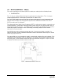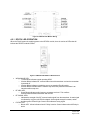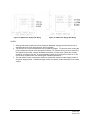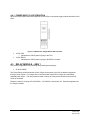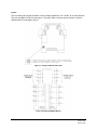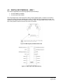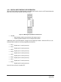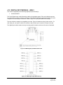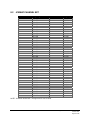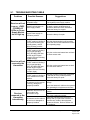
1
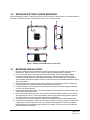
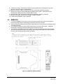
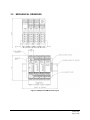
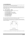
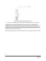
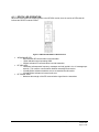
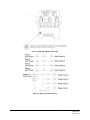
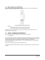
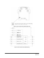
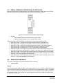
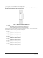
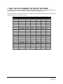
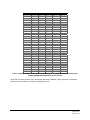
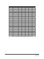
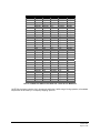
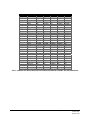
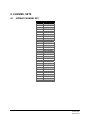
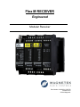
Flex M RECEIVER Engineered Modular Receiver Part Number: 198-80104-1100 R0 October 2014 © 2014 Magnetek Your New Radio Receiver Thank you for your purchase of Magnetek’s Flex M Receiver Radio Remote Equipment Control. Magnetek has set a whole new standard in radio-remote performance, dependability, and value with this line of modular receivers. If your product ever needs modification or service, please contact one of our representatives at the following locations: U.S. Service Information For questions regarding service or technical information contact: 1.866.MAG.SERV 1.866.624.7378 International Service: +1.262.783.3500 Magnetek, Inc. N49 W13650 Campbell Drive Menomonee Falls, WI 53051 Telephone: Website: E-mail: +1.800.288.8178 www.magnetek.com [email protected] Fax Numbers: Main: +1.800.298.3503 Sales: +1.262.783.3510 Service: +1.262.783.3508 Canada Service Information: 4090B Sladeview Crescent Mississauga, Ontario L5L 5Y5 Canada Phone: +1.800.792.7253 Fax: +1.905.828.5707 +1.416.424.7617 (24/7 Service pager) EU Market Contact: Brian Preston Magnetek (UK) Ltd. Unit 3 Bedford Business Centre, Mile Road Bedford, MK42 9TW UK Phone: +44.1234.349191 Fax: +44.1234.268955 ©2014 MAGNETEK All rights reserved. This notice applies to all copyrighted materials included with this product, including, but not limited to, this manual and software embodied within the product. This manual is intended for the sole use of the person(s) to whom it was provided, and any unauthorized distribution of the manual or dispersal of its contents is strictly forbidden. This manual may not be reproduced in whole or in part by any means whatsoever without the expressed written permission of MAGNETEK. TABLE OF CONTENTS 1. PRODUCT MANUAL SAFETY INFORMATION ................................................................................ 5 2. CRITICAL INSTALLATION CONSIDERATIONS ............................................................................... 7 2.1 GENERAL ..................................................................................................................................... 7 2.2 PERSONS AUTHORIZED TO OPERATE RADIO CONTROLLED EQUIPMENT ....................... 7 2.3 SAFETY INFORMATION & RECOMMENDED TRAINING FOR OPERATORS .......................... 8 2.4 PRE-OPERATION TEST .............................................................................................................. 9 3. FLEX M INSTALLATION .................................................................................................................. 10 3.1 PRE-INSTALLATION .................................................................................................................. 10 3.2 RECEIVER UNIT MOUNTING LOCATION CONSIDERATIONS............................................... 10 3.3 ANTENNA MOUNTING CONSIDERATIONS ............................................................................. 10 3.4 LINE INPUT CONSIDERATIONS ............................................................................................... 11 3.5 WIRING CONSIDERATION ........................................................................................................ 11 3.6 RECEIVER UNIT ENCLOSURE MOUNTING ............................................................................ 12 3.7 RECEIVER INSTALLATION ....................................................................................................... 12 3.8 REMOVAL ................................................................................................................................... 13 3.9 MECHANICAL DRAWINGS ........................................................................................................ 14 4. FLEX M MODULES.......................................................................................................................... 15 4.1 RF/CPU MODULE – GEN 1........................................................................................................ 15 4.1.1 RF/CPU LED OPERATION................................................................................................. 17 4.2 RF/CPU MODULE – GEN 2........................................................................................................ 18 4.2.1 RF/CPU LED OPERATION................................................................................................. 19 4.3 POWER SUPPLY MODULE – GEN 1 ........................................................................................ 20 4.3.1 POWER SUPPLY LED OPERATION ................................................................................. 21 4.4 POWER SUPPLY MODULE – GEN 2 ........................................................................................ 21 4.4.1 POWER SUPPLY LED OPERATION ................................................................................. 23 4.5 RELAY MODULE – GEN 1 ......................................................................................................... 23 4.5.1 RELAY MODULE LED OPERATION .................................................................................. 25 4.6 RELAY MODULE – GEN 2 ......................................................................................................... 25 4.6.1 RELAY MODULE LED OPERATION .................................................................................. 27 4.7 SERIAL COMMUNICATION MODULE ....................................................................................... 27 4.7.1 SERIAL COMMUNICATION MODULE LED OPERATION ................................................ 29 4.8 ANALOG I/O MODULE ............................................................................................................... 29 4.8.1 ANALOG I/O MODULE LED OPERATION ......................................................................... 31 4.9 DIGITAL INPUT MODULE – GEN 1 ........................................................................................... 32 4.9.1 DIGITAL INPUT MODULE LED OPERATION .................................................................... 33 4.10 DIGITAL INPUT MODULE – GEN 2 ........................................................................................... 34 4.10.1 DIGITAL INPUT MODULE LED OPERATION .................................................................... 35 5. PROGRAMMING WITH RCP .......................................................................................................... 36 6. RECEIVER CHANNEL CONFIGURATION SETTINGS .................................................................. 37 6.1 FCC STATEMENTS .................................................................................................................... 37 7. GEN 1 RF/CPU CHANNEL DIP SWITCH SETTINGS .................................................................... 38 8. CHANNEL SETS .............................................................................................................................. 43 8.1 433MHz CHANNEL SET............................................................................................................. 43 8.2 419MHz CHANNEL SET............................................................................................................. 44 8.3 2.4 GHz: FHSS............................................................................................................................ 45 9. TROUBLESHOOTING ..................................................................................................................... 46 9.1 TROUBLESHOOTING TABLE.................................................................................................... 47 10. NOTES ............................................................................................................................................. 49 1. PRODUCT MANUAL SAFETY INFORMATION Magnetek, Inc. (Magnetek) offers a broad range of radio remote control products, control products and adjustable frequency drives, and industrial braking systems for overhead material handling applications. This manual has been prepared by Magnetek to provide information and recommendations for the installation, use, operation and service of Magnetek’s material handling products and systems (Magnetek Products). Anyone who uses, operates, maintains, services, installs or owns Magnetek Products should know, understand and follow our instructions and safety recommendations in this manual for Magnetek Products. The recommendations in this manual do not take precedence over any of the following requirements relating to cranes, hoists and lifting devices: Instructions, manuals, and safety warnings of the manufacturers of the equipment where the radio system is used, Plant safety rules and procedures of the employers and the owners of facilities where the Magnetek Products are being used, Regulations issued by the Occupational Health and Safety Administration (OSHA), Applicable local, state or federal codes, ordinances, standards and requirements, or Safety standards and practices for the overhead material handling industry. This manual does not include or address the specific instructions and safety warnings of these manufacturers or any of the other requirements listed above. It is the responsibility of the owners, users and operators of the Magnetek Products to know, understand and follow all of these requirements. It is the responsibility of the owner of the Magnetek Products to make its employees aware of all of the above listed requirements and to make certain that all operators are properly trained. No one should use Magnetek Products prior to becoming familiar with and being trained in these requirements. WARRANTY INFORMATION FOR INFORMATION ON MAGNETEK’S PRODUCT WARRANTIES BY PRODUCT TYPE, PLEASE VISIT WWW.MAGNETEK.COM. Flex M Engineered Receiver Instruction Manual October 2014 Page 5 of 49 WARNINGS and CAUTIONS Throughout this document WARNING and CAUTION statements have been deliberately placed to highlight items critical to the protection of personnel and equipment. WARNING – A warning highlights an essential operating or maintenance procedure, practice, etc. which if not strictly observed, could result in injury or death of personnel, or long term physical hazards. Warnings are highlighted as shown below: WARNING CAUTION – A caution highlights an essential operating or maintenance procedure, practice, etc. which if not strictly observed, could result in damage to, or destruction of equipment, or loss of functional effectiveness. Cautions are highlighted as shown below: CAUTION WARNINGS and CAUTIONS SHOULD NEVER BE DISREGARDED The safety rules in this section are not intended to replace any rules or regulations of any applicable local, state, or federal governing organizations. Always follow your local lockout and tagout procedure when maintaining any radio equipment. The following information is intended to be used in conjunction with other rules or regulations already in existence. It is important to read all of the safety information contained in this section before installing or operating the Radio Control System. Flex M Engineered Receiver Instruction Manual October 2014 Page 6 of 49 2. CRITICAL INSTALLATION CONSIDERATIONS WARNING PRIOR TO INSTALLATION AND OPERATION OF THIS EQUIPMENT, READ AND DEVELOP AN UNDERSTANDING OF THE CONTENTS OF THIS MANUAL AND THE OPERATION MANUAL OF THE EQUIPMENT OR DEVICE TO WHICH THIS EQUIPMENT WILL BE INTERFACED. FAILURE TO FOLLOW THIS WARNING COULD RESULT IN SERIOUS INJURY OR DEATH AND DAMAGE TO EQUIPMENT. ALL EQUIPMENT MUST HAVE A MAINLINE CONTACTOR INSTALLED AND ALL TRACKED CRANES, HOISTS, LIFTING DEVICES AND SIMILAR EQUIPMENT MUST HAVE A BRAKE INSTALLED. FAILURE TO FOLLOW THIS WARNING COULD RESULT IN SERIOUS INJURY OR DEATH AND DAMAGE TO EQUIPMENT. AN AUDIBLE AND/OR VISUAL WARNING MEANS MUST BE PROVIDED ON ALL REMOTE CONTROLLED EQUIPMENT AS REQUIRED BY CODE, REGULATION, OR INDUSTRY STANDARD. THESE AUDIBLE AND/OR VISUAL WARNING DEVICES MUST MEET ALL GOVERNMENTAL REQUIREMENTS. FAILURE TO FOLLOW THIS WARNING COULD RESULT IN SERIOUS INJURY OR DEATH AND DAMAGE TO EQUIPMENT. FOLLOW YOUR LOCAL LOCKOUT TAGOUT PROCEDURE BEFORE MAINTAINING ANY REMOTE CONTROLLED EQUIPMENT. ALWAYS REMOVE ALL ELECTRICAL POWER FROM THE CRANE, HOIST, LIFTING DEVICE OR SIMILAR EQUIPMENT BEFORE ATTEMPTING ANY INSTALLATION PROCEDURES. DEENERGIZE AND TAGOUT ALL SOURCES OF ELECTRICAL POWER BEFORE TOUCH-TESTING ANY EQUIPMENT. FAILURE TO FOLLOW THIS WARNING COULD RESULT IN SERIOUS INJURY OR DEATH AND DAMAGE TO EQUIPMENT. THE DIRECT OUTPUTS OF THIS PRODUCT ARE NOT DESIGNED TO INTERFACE DIRECTLY TO TWO STATE SAFETY CRITICAL MAINTAINED FUNCTIONS, I.E., MAGNETS, VACUUM LIFTS, PUMPS, EMERGENCY EQUIPMENT, ETC. A MECHANICALLY LOCKING INTERMEDIATE RELAY SYSTEM WITH SEPARATE POWER CONSIDERATIONS MUST BE PROVIDED. FAILURE TO FOLLOW THIS WARNING COULD RESULT IN SERIOUS INJURY OR DEATH OR DAMAGE TO EQUIPMENT. 2.1 GENERAL Radio controlled material handling equipment operates in several directions. Cranes, hoists, lifting devices and other material handling equipment can be large, and operate at high speeds. Quite frequently, the equipment is operated in areas where people are working in close proximity to the material handling equipment. The operator must exercise extreme caution at all times. Workers must constantly be alert to avoid accidents. The following recommendations have been included to indicate how careful and thoughtful actions may prevent injuries, damage to equipment, or even save a life. 2.2 PERSONS AUTHORIZED TO OPERATE RADIO CONTROLLED EQUIPMENT Only properly trained persons designated by management should be permitted to operate radio controlled equipment. Radio controlled cranes, hoists, lifting devices and other material handling equipment should not be operated by any person who cannot read or understand signs, notices and operating instructions that pertain to the equipment. Radio controlled equipment should not be operated by any person with insufficient eyesight or hearing or by any person who may be suffering from a disorder or illness, is taking any medication that may cause loss of equipment control, or is under the influence of alcohol or drugs. Flex M Engineered Receiver Instruction Manual October 2014 Page 7 of 49 2.3 SAFETY INFORMATION & RECOMMENDED TRAINING FOR OPERATORS Anyone being trained to operate radio controlled equipment should possess as a minimum the following knowledge and skills before using the radio controlled equipment. The operator should: Have knowledge of hazards pertaining to equipment operation Have knowledge of safety rules for radio controlled equipment Have the ability to judge distance of moving objects Know how to properly test prior to operation Be trained in the safe operation of the radio receiver as it pertains to the crane, hoist, lifting device or other material handling equipment being operated Have knowledge of the use of equipment warning lights and alarms Have knowledge of the proper storage space for a radio control receiver when not in use Be trained in transferring a radio control receiver to another person Be trained how and when to report unsafe or unusual operating conditions Test the receiver emergency stop and all warning devices prior to operation; testing should be done on each shift, without a load Be thoroughly trained and knowledgeable in proper and safe operation of the crane, hoist, lifting device, or other material handling equipment that utilizes the radio control Know how to keep the operator and other people clear of lifted loads and to avoid “pinch” points Continuously watch and monitor status of lifted loads Know and follow cable and hook inspection procedures Know and follow the local lockout and tagout procedures when servicing radio controlled equipment Know and follow all applicable operating and maintenance manuals, safety procedures, regulatory requirements, and industry standards and codes The operator shall not: Lift or move more than the rated load Operate the material handling equipment if the direction of travel or function engaged does not agree with what is indicated on the controller Use the crane, hoist or lifting device to lift, support or transport people Lift or carry any loads over people Operate the crane, hoist or lifting device unless all persons, including the operator, are and remain clear of the supported load and any potential pinch points Operate a crane, hoist, or lifting device when the device is not centered over the load Operate a crane, hoist, or lifting device if the chain or wire rope is not seated properly in the sprockets, drum or sheave Operate any damaged or malfunctioning crane, hoist, lifting device or other material handling equipment Change any settings or controls without authorization and proper training Remove or obscure any warning or safety labels or tags Leave any load unattended while lifted Leave power on the radio controlled equipment when the equipment is not in operation Flex M Engineered Receiver Instruction Manual October 2014 Page 8 of 49 Operate any material handling equipment using a damaged controller because the unit may be unsafe Operate manual motions with other than manual power Operate radio controlled equipment when low battery indicator is on WARNING THE OPERATOR SHOULD NOT ATTEMPT TO REPAIR ANY RADIO CONTROLLER. IF ANY PRODUCT PERFORMANCE OR SAFETY CONCERNS ARE OBSERVED, THE EQUIPMENT SHOULD IMMEDIATELY BE TAKEN OUT OF SERVICE AND BE REPORTED TO THE SUPERVISOR. DAMAGED AND INOPERABLE RADIO CONTROLLER EQUIPMENT SHOULD BE RETURNED TO MAGNETEK FOR EVALUATION AND REPAIR. FAILURE TO FOLLOW THIS WARNING COULD RESULT IN SERIOUS INJURY OR DEATH AND DAMAGE TO EQUIPMENT. 2.4 PRE-OPERATION TEST At the start of each work shift, or when a new operator takes control of the crane, operators should do, as a minimum, the following steps before making lifts with any crane or hoist: Test all warning devices. Test all direction and speed controls. Test the receiver emergency stop. Flex M Engineered Receiver Instruction Manual October 2014 Page 9 of 49 3. FLEX M INSTALLATION WARNING BEFORE OPERATING THE RECEIVER FAMILIARIZE YOURSELF WITH ALL SAFETY INFORMATION IN THIS MANUAL, APPROPRIATE MANUAL SUPPLEMENTS AND ANY OTHER LOCAL, STATE, OR FEDERAL RULES OR REGULATIONS ALREADY IN EXISTENCE. FAILURE TO FOLLOW THIS WARNING COULD RESULT IN SERIOUS INJURY OR DEATH AND DAMAGE TO EQUIPMENT. 3.1 PRE-INSTALLATION 1. Transmitter and receiver access code, channel, and project ID must match before the system will communicate. 2. Be aware of other radio channels in the surrounding area - set your system to a unique channel. 3. Make sure that your equipment is working properly in manual mode prior to system installation. 4. Make sure the power to the receiver is the correct voltage and current. 5. Disconnect equipment power prior to system installation. 3.2 RECEIVER UNIT MOUNTING LOCATION CONSIDERATIONS Ensure the mounting location is as far as possible from exposed trolley wires and sources of electromagnetic or radiated noise as possible. The mounting surface must be smooth and continuous. Mounting the receiver unit on uneven surfaces could cause warping or stress internal components. If possible, avoid installing the receiver unit to a surface where high vibration or shock is present. If this cannot be avoided, use appropriate shock mounts. 3.3 ANTENNA MOUNTING CONSIDERATIONS It is best to mount the antenna so that it is visible to the operator. This is usually accomplished by mounting the antenna under the crane. However, it is not recommended to point the antenna straight down, as this will cause a “dead” spot directly under the antenna. The antenna should be mounted at a 45 degree angle perpendicular to the operator. Always try to avoid power sources, motors, drives, brakes, etc., when installing the antenna. If necessary, Magnetek offers an external antenna kit. Flex M Engineered Receiver Instruction Manual October 2014 Page 10 of 49 3.4 LINE INPUT CONSIDERATIONS WARNING THE UNIT MUST BE WIRED TO THE CORRECT VOLTAGE, AND BE CONNECTED TO THE CORRECT TERMINAL AS REQUIRED BY THE ACTUAL LINE VOLTAGE. FAILURE TO FOLLOW THIS WARNING COULD RESULT IN SERIOUS INJURY OR DEATH AND DAMAGE TO EQUIPMENT. Refer to Sections 4.3 and 4.4 for information on how to configure the unit’s power supply modules. NOTE: The receiver unit should not be connected to lines containing excessive power-up transients or continuous commutator noise. A line conditioner may be necessary in some installations. 3.5 1. 2. 3. 4. 5. 6. 7. 8. 9. 10. WIRING CONSIDERATION Read this manual before installation. Please observe appropriate local and National Electrical Codes when wiring electrical devices. Do not connect/disconnect wiring or perform circuit checks while the power is turned on. The motor wiring and the power wiring should also be in separate metal conduits. Low voltage wires shall be wired with proper low voltage class wiring procedures. Control wiring as well as antenna wiring shall be in separate conduit and shall be kept as short as possible. All terminals shall be tightened to specified terminal torque between 4.4 IN-LBS (.5 N·m) and 5.3 IN-LBS (.6 N·m), unless otherwise specified. Remove excess metal screws, metal filings, and wire clippings from inside of unit. Inspect to make sure no exposed wire has contact with any other wiring or terminals. RC type suppressors are strongly recommended on all contactors. Flex M Engineered Receiver Instruction Manual October 2014 Page 11 of 49 3.6 RECEIVER UNIT ENCLOSURE MOUNTING When mounting the receiver, make sure to allow room for the door to swing open if it is mounted within an enclosure. Mount the receiver unit cabinet securely to the mounting surface. Flex Flex Flex Flex Figure 1. Example of Flex M Mounted in an Enclosure 3.7 RECEIVER INSTALLATION 1. Be sure to mount the receiver antenna in direct line-of-sight of the operator and free from all obstructions. Refer to Section 3.3 for recommendations regarding antenna mounting. 2. Do not mount the receiver near high levels of electrical noise, such as unshielded variable frequency drives, as they may cause minor interference. When mounting the Flex M near unshielded variable frequency drives Magnetek typically recommends that the Flex M and all antenna cable routing be mounted a minimum of 24 inches from all unshielded variable frequency drives and cables. 3. Allow adequate room for mounting the receiver. Be sure to allow a minimum of 5” between the connector and nearest surface to allow for cable harness connections. 4. For best reception, and to help protect connectors from moisture and water damage, mount the receiver in an upright position. 5. If obstructions cannot be cleared, or if the unit must be mounted inside of a metal enclosure, the remote antenna should be used. 6. Do not enclose the antenna in steel. If the receiver is mounted within an enclosure, an external antenna MUST be used. For the best reception, keep all metal objects away from the antenna. Consult the factory for more information regarding your application. 7. The power source to the Flex M system must have a master disconnect and should be fused. 8. It should not be necessary to set the Access Code or channel, as they are preset. If special field programming is needed, power the unit up on the bench and program the unit for any special configurations or other parameters (see Section 5 for details). The unit can be re-programmed after it is installed if necessary. Flex M Engineered Receiver Instruction Manual October 2014 Page 12 of 49 9. Position the receiver; make sure to locate it as far as possible from exposed trolley wire and sources of electromagnetic or radiated noise. 10. Mount the receiver. Refer to Section 3.8 for further information regarding mounting. 11. Wire the unit using the electrical drawings provided with the system. Each section for the modules also indicates how the module should be wired. 12. Wire the power input for the input power type as described in Sections 4.3 and 4.4. 13. Wiring of the system should now be complete. Install the antenna. 14. If there are any problems, refer to Section 9. 3.8 REMOVAL 1. To remove modules from the rail for service, first ensure all power to the Flex M modules has been turned off and proper lockout/tagout procedures have been followed. 2. Remove one end rail clamp and un-nest the module that you wish to remove by separating it from the others on the rail. 3. Use a slotted screwdriver to lift the DIN rail release tab on the top of the module. Swing the module down and away from the top tab/ring and unhook from the rail. 4. The PCB from any module can be removed from its housing by pressing in both tabs first (tabs are on the front and back sides of the housing); then the top housing and PCB can be removed from the lower housing (see figure below for details). Figure 2. Flex M Housing Removal Detail Flex M Engineered Receiver Instruction Manual October 2014 Page 13 of 49 3.9 MECHANICAL DRAWINGS Figure 3. Example Flex M Mechanical Layout Flex M Engineered Receiver Instruction Manual October 2014 Page 14 of 49 4. FLEX M MODULES The Flex M system comprises of a RF/CPU module and a power supply module with application specific add-on cards in between the CPU module and power supply module. During the operation of the receiver, the LED indicators will allow observation of the status of each of the modules of the Flex M receiver. Refer to each of the sections below for specific information regarding each of the modules. Be sure to reference the correct part number for each module type as some of the modules have different versions. 4.1 RF/CPU MODULE – GEN 1 This section is applicable to the following RF/CPU module part number(s): 25-02-074-800E (900MHz Part 15) 25-02-074-801E (400MHz Legacy Communication) 25-02-074-807E (900MHz 1W) – No longer available 25-02-074-815E (900MHz 200mW) – No longer available 25-02-074-816E (433MHz Part 15) 25-02-074-818E (2.4GHz 50mW) 25-02-074-819E (2.4GHz 125mW) 25-02-074-821E (400-420MHz) 25-02-074-822E (410-430MHz) NOTE: The high power RF/CPU Module 25-02-074-807E draws up to 1300mA of power when in use. It requires high current power supply module 25-02-074-810E to perform properly. The Flex RF/CPU Module is the main module that receives radio signals from a paired transmitter and interprets those signals into the appropriate response for the attached I/O modules. There is one RF/CPU module in the Flex M System. Figure 4. GEN1 RF/CPU Module Detail View (For all RF/CPU modules except 900MHz 1W (25-02-074-807E) & 900MHz 200mW (25-02-074-815E)) Flex M Engineered Receiver Instruction Manual October 2014 Page 15 of 49 Figure 5. GEN1 High Power RF/CPU Module Detail View (For RF/CPU modules 900MHz 1W (25-02-074-807E) & 900MHz 200mW (25-02-074-815E) only) The dip switches are used to set the channel and to set relay output type. The dip switches can be accessed by removing the module from the rail (see Section 3.8 for details on how to remove the modules from the rail). After removing the RF/CPU module from the din rail, press in the tabs to release the PCB from the housing (see Section 3.8 for details) and set the dip switches as necessary for the Flex M system utilized. There are no wires to attach to the RF/CPU module aside from either an antenna or a coaxial cable on the TNC antenna connection. For channel dip switch settings for each of the different RF types, refer to the appropriate table in Section 7. Flex M Engineered Receiver Instruction Manual October 2014 Page 16 of 49 4.1.1 RF/CPU LED OPERATION When the Flex M system is supplying power to the RF/CPU module, there is a series of LEDs that will indicate the RF/CPU module’s status. Figure 6. GEN1 RF/CPU Module LED Placement WDG/ONLINE LED: o Solid indicates RF communication with transmitter o 1 Blink indicates normal operating WDG o 2 Blinks indicates RF communication loss with transmitter RF MSG LED: o Fast Blinks indicates radio frequency messages received (typical is 4 to 10 messages per second). This confirms communication between transmitter and receiver o 3 Steady Blinks indicates read/write error to an attached Flex M module o 4 Steady Blinks indicates an internal radio error RF SIGNAL LEDs o Measures the strength of the RF communication signal from the transmitter Flex M Engineered Receiver Instruction Manual October 2014 Page 17 of 49 4.2 RF/CPU MODULE – GEN 2 This section is applicable to the following RF/CPU module part number(s) with the following format: 198-80104-yRFxxx The “x” in the part number indicates the frequency and power level of the module. The “y” in the part number indicated which RF module type is present (Part 15, Part 90, ETSI). The Flex RF/CPU Module is the main module that receives radio signals from a paired transmitter and interprets those commands into an appropriate response to the attached I/O modules. There is one RF/CPU module in the Flex M System. The software application, Radio Control Programmer (RCP), is used to set the channel, access code, and virtual dip switches. Communication and configuration is done through J2, the USB connector, which is located opposite the RF connection. In addition to the RF connection to the RP-SMA antenna, the CPU module also contains connections for the E-STOP relays, an auxiliary CAN port, and an external connection for IR communication. The E-STOP output can be configured as either NO or NC. This is set via J8 (NO) or J10 (NC). To configure the output, remove the module as described in Section 3.8 and then reference Figure 7 for the location of jumpers J8 and J10. The external CAN bus is not intended to be used for communication outside of the receiver system. This is intended for future expansion of the Flex M platform. For CAN bus communication outside of the Flex M receiver system, a communication module will need to be used within the system. Jumper J1 is used to indicate if the CAN bus termination resistor is used or not. Figure 7. GEN2 RF/CPU Module Detail View Flex M Engineered Receiver Instruction Manual October 2014 Page 18 of 49 Figure 8. GEN2 RF/CPU Module Wiring 4.2.1 RF/CPU LED OPERATION When the Flex M system is supplying power to the RF/CPU module, there is a series of LEDs that will indicate the RF/CPU module’s status. Figure 9. GEN2 RF/CPU Module LED Placement WDG/ONLINE LED: o 1 Green Blink indicates normal operating WDG o 2 Amber Blinks indicates RF communication loss with transmitter or when the transmitter is powered off o 3 Amber Blinks indicates a read/write error to an attached Flex M module o 6 Amber Blinks indicates that the machine stop has been pressed or that there is an internal machine stop error RF MSG LED: o Green Blinks indicates radio frequency messages received. This confirms communication between transmitter and receiver. RF SIGNAL LEDs: o Indicates the strength of the RF communication signal from the transmitter. A weak signal is indicated by only the red LEDs illuminated. As the signal strength increases, amber and then green LEDs will light. Green LEDs indicate a strong signal. E-STOP LED o Bicolor LED. Yellow indicator when K1 Relay is active. Green indicator when K2 Relay is active Flex M Engineered Receiver Instruction Manual October 2014 Page 19 of 49 4.3 POWER SUPPLY MODULE – GEN 1 This section is applicable to the following power supply module part number(s): 25-02-074-804E (120VAC 15VA, 1000mA) 25-02-074-810E (9-18VDC @1.5A 25VA, 1500mA) – No longer available 25-02-074-820E (9-36VDC 15VA, 1000mA) The Flex M power supply module converts the supply power to 5VDC power for all the attached Flex M modules. This power module has a maximum output supply current of 1000mA. There is one power supply module in the Flex M system. Figure 10. GEN1 Power Supply Module Detail View Figure 11. GEN1 Power Supply VAC Wiring Figure 12. GEN1 Power Supply VDC Wiring NOTES: 1. Although the power module has built-in protection, Magnetek strongly recommends the use of external fuses and circuit disconnects for all Flex modules. 2. The built-in fuse is not user serviceable but can be checked if troubleshooting. To check the fuse, remove the power module from the din rail as described in Section 3.8. The fuse location is shown in Figure 10. Use a multimeter to check for continuity across the fuse. If the fuse is blown, contact Magnetek to send the module in for service. 3. The total system current consumption should not exceed the maximum output supply current of the power supply module. If additional supply current is required, contact the factory for a custom solution. Flex M Engineered Receiver Instruction Manual October 2014 Page 20 of 49 4.3.1 POWER SUPPLY LED OPERATION When the Flex M system has power supplied, the two LEDs on the power supply module should be lit and solid. Figure 13. GEN1 Power Supply Module LED Placement 4.4 +5VDC CPU o Indicates that +5VDC power is going to the CPU +5VDC RELAY o Indicates that +5VDC power is going to the RELAY modules POWER SUPPLY MODULE – GEN 2 This section is applicable to the following power supply module part number(s): 198-80104-PSAC00 (85-265VAC) 198-80104-PSDC00 (6-36VDC) 198-80104-PSLAC0 (24-48VAC) All of the Flex M power supply modules convert their input supply power to a nominal 5VDC output for all the attached Flex M modules. This power module has a maximum output supply current of 2000mA (shared between CPU & relay outputs). There is one power supply module in the Flex M system. Figure 14. GEN2 Power Supply Module Detail View Flex M Engineered Receiver Instruction Manual October 2014 Page 21 of 49 Figure 15. GEN2 Power Supply VAC Wiring Figure 16. GEN2 Power Supply VDC Wiring NOTES: 1. Although the power module has built-in protection, Magnetek strongly recommends the use of external fuses and circuit disconnects for all Flex modules. 2. The built-in fuse is user serviceable and can be replaced if blown. To check the fuse, remove the power module from the din rail as described in Section 3.8. Remove the top cover to reveal FH1, the cylindrical fuse holder. Using a flat-bladed screwdriver, turn the cap a quarter turn counterclockwise, and remove the cap. Use a multimeter to check for continuity across the fuse. If the fuse is blown, replace with a fuse matching the installed specifications. 3. The total system current consumption should not exceed the maximum output supply current of the power supply module. If additional supply current is required, contact the factory for a custom solution. Flex M Engineered Receiver Instruction Manual October 2014 Page 22 of 49 4.4.1 POWER SUPPLY LED OPERATION When the Flex M system has power supplied, the two LEDs on the power supply module should be lit and solid. Figure 17. GEN2 Power Supply Module LED Placement 4.5 +5VDC CPU o Indicates that +5VDC power is going to the CPU +5VDC RELAY o Indicates that +5VDC power is going to the RELAY modules RELAY MODULE – GEN 1 This section is applicable to the following relay module part number(s): 25-02-074-805E The Flex M Relay module allows the control of high current power (up to 5A) for attached equipment through 8 relay outputs. Four relays have a common power input and four relays have individually separate power inputs. The relay module number is set by the rotary switch located on the lower left corner of the board. Relays are rated for 10 Amps 277VAC/30VDC, 1 HP 240VAC, but fused for 5A. External suppression for the relays is needed. Flex M Engineered Receiver Instruction Manual October 2014 Page 23 of 49 Figure 18. GEN1 Relay Module Detail View Figure 19. GEN1 Relay Module Wiring Flex M Engineered Receiver Instruction Manual October 2014 Page 24 of 49 4.5.1 RELAY MODULE LED OPERATION When the Flex M system is supplying power to the Relay module, there is an LED that indicates the power and communication status of the Relay module. Figure 20. GEN1 Relay Module LED Placement OK LED o Solid indicates module communication with system is good o 3 Blinks indicates read/write error to attached CPU module Additionally, there are 8 LEDs labeled 1 through 8 on the Relay module. When the LED is on, this indicates that the relay is closed/activated. 4.6 RELAY MODULE – GEN 2 This section is applicable to the following relay module part number(s): 198-80104-RLY01 All output relay contacts are rated for 8 Amps 277VAC/30VDC, 1 HP 240VAC for maximum life and surge protection, and protected with MOVs. Connection to equipment or contactors with higher voltage or current requirements will require intermediate relays. The Flex M Relay module allows the control of high current power (up to 8A) for attached equipment through 8 relay outputs. All eight relays have individual inputs contacts, and two relays K1 and K2 can be configured manually for either normally open (NO) or normally closed (NC) contacts. To configure K1 and K2, remove the board as described in Section 3.8, then refer to Figure 21 for the appropriate jumper setting. The relay module number is set by the rotary switch located on the lower left corner of the board. Flex M Engineered Receiver Instruction Manual October 2014 Page 25 of 49 Figure 21. GEN2 Relay Module Detail View Figure 22. GEN2 Relay Module Wiring Flex M Engineered Receiver Instruction Manual October 2014 Page 26 of 49 4.6.1 RELAY MODULE LED OPERATION When the Flex M system is supplying power to the Relay module, there is an LED that indicates the power and communication status of the Relay module. Figure 23. GEN2 Relay Module LED Placement OK LED o Solid indicates module communication with system is good o 3 Blinks indicates read/write error to attached CPU module Additionally, there are 8 LEDs labeled 1 through 8 on the Relay module. When the LED is on, this indicates that the relay is activated. 4.7 SERIAL COMMUNICATION MODULE This section is applicable to the following serial communication part number(s): 25-02-074-809E The Flex M Serial Communication module allows the communication via RS-232 (2-wire only), RS-422 (4wire only), or RS-485 (4-wire only). Any of these interfaces can operate in full duplex, while only RS-232 supports half duplex operation. When operating in full duplex with RS-422 and RS-485, the communication module must always be the master. The communication module can only operate as a slave in half duplex mode. The Serial Communication module also support CAN-BUS 2.0B. The Serial Communications module number is set by the rotary switch located on the lower left corner of the board. Flex M Engineered Receiver Instruction Manual October 2014 Page 27 of 49 Figure 24. Serial Communications Module Detail View Figure 25. Serial Communications Module Wiring Flex M Engineered Receiver Instruction Manual October 2014 Page 28 of 49 4.7.1 SERIAL COMMUNICATION MODULE LED OPERATION When the Flex M system is supplying power to the Serial Communication module, there is an LED that indicates the power and communication status of the Serial Communication module. Figure 26. Serial Communications Module LED Placement OK LED o Solid indicates module communication with system is good o 3 Blinks indicates read/write error to attached CPU module Additionally, there are 8 LEDs labeled 1 through 8 on the Serial Communication module. When LED number 1 is steady, this indicates an internal CAN bus initialization error. When LED number 2 is steady, this indicates an external CAN bus initialization error. When LED number 2 is blinking, this indicates message reception on the external CAN bus. When LED number 3 is blinking, this indicates that the Serial Communication Card is communicating with the attached drive. This is only applicable for RDSI systems. When LED number 5 is on steady, this indicates there is a serial communication time-out error (the serial communication was inactive for 1 second). See Section 9 for additional information. When LED number 6 is on steady, this indicates that the Serial Communication is in test mode. When LED number 7 is on steady, this indicates that the CPU module is sending a drive forward command. This is only applicable for RDSI systems. When LED number 8 is on steady, this indicates that the CPU module is sending a drive reverse command. This is only applicable for RDSI systems. 4.8 ANALOG I/O MODULE This section is applicable to the following analog I/O part number(s): 25-02-074-806E Outputs: The four analog output signals are able to send voltage signals from 0 to +/-10VDC, at an 8-bit resolution. These outputs are for reference voltage only, so each one can only supply 20mA of current. The outputs share a common ground reference, which is isolated from the Flex M system ground and any additional I/O card output ground. These outputs can be preconfigured at the factory for different voltage ranges (ex. 0-5VDC, or 3-6-9VDC). Flex M Engineered Receiver Instruction Manual October 2014 Page 29 of 49 Inputs: The four analog input signals are able to receive voltage signals from 0 to +10VDC, at an 8-bit resolution. The input impedance is 20K for these inputs. The inputs share a common ground reference, which is shared with the Flex M system ground. Figure 27. Analog I/O Module Detail View Figure 28. Analog I/O Module Wiring Flex M Engineered Receiver Instruction Manual October 2014 Page 30 of 49 4.8.1 ANALOG I/O MODULE LED OPERATION When the Flex M system is supplying power to the Analog I/O module, there is an LED that indicates the power and communication status of the Analog I/O module. Figure 29. Analog I/O Module LED Placement OK LED o Solid indicates module communication with system is good o 3 Blinks indicates read/write error to attached CPU module Additionally, there are 8 LEDs labeled 1 through 8 on the Analog I/O module. When the LED is on, this indicates that the module is sending/receiving a signal on that input or output. LED1 o LED2 o LED3 o LED4 o LED5 o LED6 o LED7 o LED8 o Analog Output 1 is Active (non-zero) Analog Output 2 is Active (non-zero) Analog Output 3 is Active (non-zero) Analog Output 4 is Active (non-zero) Analog Input 1 is Active (non-zero) Analog Input 2 is Active (non-zero) Analog Input 3 is Active (non-zero) Analog Input 4 is Active (non-zero) Flex M Engineered Receiver Instruction Manual October 2014 Page 31 of 49 4.9 DIGITAL INPUT MODULE – GEN 1 This section is applicable to the following digital input part number(s): 25-02-074-808E (12-24VDC) 25-02-074-817E (50-75VDC) The Flex M Digital Input module allows the reading of twelve digital signals (12-24VDC or 50-75VDC). Custom DC voltage inputs are available upon request. The DC power is not supplied by the card, so a separate power supply needs to be installed to the power inputs. The digital input module number is set by the rotary switch located on the lower left corner of the board. Figure 30. GEN1 Digital Input Module Detail View Figure 31. GEN1 Digital Input Module Wiring Flex M Engineered Receiver Instruction Manual October 2014 Page 32 of 49 4.9.1 DIGITAL INPUT MODULE LED OPERATION When the Flex M system is supplying power to the Digital Input module, there is an LED that indicates the power and communication status of the Relay module. Figure 32. GEN1 Digital Input Module LED Placement OK LED o Solid indicates module communication with system is good o 3 Blinks indicates read/write error to attached CPU module Additionally, there are 8 LEDs labeled 1 through 8 on the Digital Input module. When the LED is on, this indicates that the module is receiving a signal/input at that input. LED1 o LED2 o LED3 o LED4 o LED5 o LED6 o LED7 o LED8 o Digital Input 1 is active (non-zero) Digital Input 2 is active (non-zero) Digital Input 3 is active (non-zero) Digital Input 4 is active (non-zero) Digital Input 5 is active (non-zero) Digital Input 6 is active (non-zero) Digital Input 7 is active (non-zero) Digital Input 8 is active (non-zero) Inputs 9-12 do not have a viewable LED. Flex M Engineered Receiver Instruction Manual October 2014 Page 33 of 49 4.10 DIGITAL INPUT MODULE – GEN 2 This section is applicable to the following digital input part number(s): 198-80104-DNPT1 The Flex M Digital Input module allows the reading of eight digital signals. Each of the digital inputs can be configured for a range of 4-36V (Low Range) or 36V-240V (High Range) operation for either AC or DC voltages via a manual jumper connection. Refer to Figure 33 for jumper locations and settings. The input reference voltage is not supplied by the card. Figure 34 shows the wiring for the module. For each input pair, one input is used for the reference and the other input is used for the input to be read. The digital input module number is set by the rotary switch located on the lower left corner of the board. Figure 33. GEN2 Digital Input Module Detail View Figure 34. GEN2 Digital Input Module Wiring Flex M Engineered Receiver Instruction Manual October 2014 Page 34 of 49 4.10.1 DIGITAL INPUT MODULE LED OPERATION When the Flex M system is supplying power to the Digital Input module, there is an LED that indicates the power and communication status of the Digital Input module. Figure 35. GEN2 Digital Input Module LED Placement OK LED o Solid indicates module communication with system is good o 3 Blinks indicates read/write error to attached CPU module Additionally, there are 8 LEDs labeled 1 through 8 on the Digital Input module. When the LED is on, this indicates that the module is receiving a signal/input at that input. LED1 o LED2 o LED3 o LED4 o LED5 o LED6 o LED7 o LED8 o Digital Input 1 is active (non-zero) Digital Input 2 is active (non-zero) Digital Input 3 is active (non-zero) Digital Input 4 is active (non-zero) Digital Input 5 is active (non-zero) Digital Input 6 is active (non-zero) Digital Input 7 is active (non-zero) Digital Input 8 is active (non-zero) Flex M Engineered Receiver Instruction Manual October 2014 Page 35 of 49 5. PROGRAMMING WITH RCP Using the optional Radio Control Programmer (RCP) software makes programming of the Flex M easier and allows for settings to be saved for future reference. WARNING THE USE OF RCP (RADIO CONTROL PROGRAMMER) IS INTENDED FOR USE BY AUTHORIZED PERSONS ONLY. CHANGES TO ANY RADIO DATA VALUE MAY LEAD TO UNEXPECTED, UNDESIRABLE, OR UNSAFE OPERATION OF EQUIPMENT AND FURTHERMORE MAY LEAD TO EQUIPMENT DAMAGE, PERSONAL INJURY, OR EVEN DEATH. ALL EQUIPMENT OPERATORS AND/OR PERSONNEL SHOULD BE NOTIFIED OF ANY RADIO DATA VALUE CHANGES THAT MAY AFFECT OPERATION. Refer to the RCP Users Guide (P/N 178-01702-0010) for information on configuring the Flex M with RCP. Flex M Engineered Receiver Instruction Manual October 2014 Page 36 of 49 6. RECEIVER CHANNEL CONFIGURATION SETTINGS 6.1 FCC STATEMENTS Compliance Statement (Part 15.19) This device complies with Part 15 of FCC rules. Operation is subject to the following two conditions: 1. This device may not cause harmful interference, and 2. This device must accept any interference received, including interference that may cause undesired operation. Warning (Part 15.21) Changes or modifications not expressly approved by the party responsible for compliance should void the user’s authority to operate the equipment. This portable transmitter with its antenna complies with FCC’s RF exposure limits for general population/uncontrolled exposure. Flex M Engineered Receiver Instruction Manual October 2014 Page 37 of 49 7. GEN 1 RF/CPU CHANNEL DIP SWITCH SETTINGS The channel can be set on the RF/CPU module via the Bank 2 dip switches. The following shows the dip switch settings for each of the channels available for each RF/CPU Module option. NOTE: See section 3.8 for instructions on how to remove the CPU/RF module from the din rail and how to remove the PCB from the module housing. Channel A B C D E F G H I J K L M N O P Q R S T U V W X Frequency 902.30 MHz 904.10 MHz 904.30 MHz 905.10 MHz 905.50 MHz 905.70 MHz 906.60 MHz 908.70 MHz 908.90 MHz 909.10 MHz 910.10 MHz 910.70 MHz 911.00 MHz 911.20 MHz 912.00 MHz 914.20 MHz 914.40 MHz 914.60 MHz 914.80 MHz 915.80 MHz 917.40 MHz 923.20 MHz 927.00 MHz 927.30 MHz SW4 DOWN UP DOWN UP DOWN UP DOWN UP DOWN UP DOWN UP DOWN UP DOWN UP DOWN UP DOWN UP DOWN UP DOWN UP SW5 DOWN DOWN UP UP DOWN DOWN UP UP DOWN DOWN UP UP DOWN DOWN UP UP DOWN DOWN UP UP DOWN DOWN UP UP SW6 DOWN DOWN DOWN DOWN UP UP UP UP DOWN DOWN DOWN DOWN UP UP UP UP DOWN DOWN DOWN DOWN UP UP UP UP SW7 UP UP UP UP UP UP UP UP DOWN DOWN DOWN DOWN DOWN DOWN DOWN DOWN UP UP UP UP UP UP UP UP SW8 DOWN DOWN DOWN DOWN DOWN DOWN DOWN DOWN UP UP UP UP UP UP UP UP UP UP UP UP UP UP UP UP Table 1. CHANNEL DIP SWITCH SETTINGS FOR 900MHZ PART 15 RF/CPU MODULE Flex M Engineered Receiver Instruction Manual October 2014 Page 38 of 49 Channel 1 2 3 4 5 6 7 8 9 10 11 12 13 14 15 16 17 18 19 20 21 22 23 24 25 26 27 28 29 30 31 32 SW4 UP DOWN UP DOWN UP DOWN UP DOWN UP DOWN UP DOWN UP DOWN UP DOWN UP DOWN UP DOWN UP DOWN UP DOWN UP DOWN UP DOWN UP DOWN UP DOWN SW5 UP UP DOWN DOWN UP UP DOWN DOWN UP UP DOWN DOWN UP UP DOWN DOWN UP UP DOWN DOWN UP UP DOWN DOWN UP UP DOWN DOWN UP UP DOWN DOWN SW6 UP UP UP UP DOWN DOWN DOWN DOWN UP UP UP UP DOWN DOWN DOWN DOWN UP UP UP UP DOWN DOWN DOWN DOWN UP UP UP UP DOWN DOWN DOWN DOWN SW7 UP UP UP UP UP UP UP UP DOWN DOWN DOWN DOWN DOWN DOWN DOWN DOWN UP UP UP UP UP UP UP UP DOWN DOWN DOWN DOWN DOWN DOWN DOWN DOWN SW8 UP UP UP UP UP UP UP UP UP UP UP UP UP UP UP UP DOWN DOWN DOWN DOWN DOWN DOWN DOWN DOWN DOWN DOWN DOWN DOWN DOWN DOWN DOWN DOWN Table 2. CHANNEL DIP SWITCH SETTINGS FOR 900MHZ @ 1W RF/CPU MODULE (25-02-074-807E) AND 900MHZ @ 200MW RF/CPU MODULE (25-02-074-815E) NOTE: Each channel consists of 50+ frequencies within 902 -928 MHz. During operation, all available frequencies will be used by a "Frequency Hopping" protocol. Flex M Engineered Receiver Instruction Manual October 2014 Page 39 of 49 Channel 1 2 3 4 5 6 7 8 9 10 11 12 13 14 15 16 17 18 19 20 21 22 23 24 25 26 27 28 29 30 31 32 Frequency 433.000 MHz 433.050 MHz 433.100 MHz 433.150 MHz 433.200 MHz 433.250 MHz 433.300 MHz 433.350 MHz 433.400 MHz 433.450 MHz 433.500 MHz 433.550 MHz 433.600 MHz 433.650 MHz 433.700 MHz 433.750 MHz 433.800 MHz 433.850 MHz 433.900 MHz 433.950 MHz 434.000 MHz 434.050 MHz 434.100 MHz 434.150 MHz 434.200 MHz 434.250 MHz 434.300 MHz 434.350 434.400 434.450 434.500 434.550 SW4 DOWN DOWN DOWN DOWN DOWN DOWN DOWN DOWN DOWN DOWN DOWN DOWN DOWN DOWN DOWN DOWN UP UP UP UP UP UP UP UP UP UP UP UP UP UP UP UP SW5 DOWN DOWN DOWN DOWN DOWN DOWN DOWN DOWN UP UP UP UP UP UP UP UP DOWN DOWN DOWN DOWN DOWN DOWN DOWN DOWN UP UP UP UP UP UP UP UP SW6 DOWN DOWN DOWN DOWN UP UP UP UP DOWN DOWN DOWN DOWN UP UP UP UP DOWN DOWN DOWN DOWN UP UP UP UP DOWN DOWN DOWN DOWN UP UP UP UP SW7 DOWN DOWN UP UP DOWN DOWN UP UP DOWN DOWN UP UP DOWN DOWN UP UP DOWN DOWN UP UP DOWN DOWN UP UP DOWN DOWN UP UP DOWN DOWN UP UP SW8 DOWN UP DOWN UP DOWN UP DOWN UP DOWN UP DOWN UP DOWN UP DOWN UP DOWN UP DOWN UP DOWN UP DOWN UP DOWN UP DOWN UP DOWN UP DOWN UP Table 3. CHANNEL DIP SWITCH SETTINGS FOR 433MHZ PART 15 Flex M Engineered Receiver Instruction Manual October 2014 Page 40 of 49 Channel 1 2 3 4 5 6 7 8 9 10 11 12 13 14 15 16 17 18 19 20 21 22 23 24 25 26 27 28 29 30 31 32 SW4 DOWN UP DOWN UP DOWN UP DOWN UP DOWN UP DOWN UP DOWN UP DOWN UP DOWN UP DOWN UP DOWN UP DOWN UP DOWN UP DOWN UP DOWN UP DOWN UP SW5 DOWN DOWN UP UP DOWN DOWN UP UP DOWN DOWN UP UP DOWN DOWN UP UP DOWN DOWN UP UP DOWN DOWN UP UP DOWN DOWN UP UP DOWN DOWN UP UP SW6 DOWN DOWN DOWN DOWN UP UP UP UP DOWN DOWN DOWN DOWN UP UP UP UP DOWN DOWN DOWN DOWN UP UP UP UP DOWN DOWN DOWN DOWN UP UP UP UP SW7 DOWN DOWN DOWN DOWN DOWN DOWN DOWN DOWN UP UP UP UP UP UP UP UP DOWN DOWN DOWN DOWN DOWN DOWN DOWN DOWN UP UP UP UP UP UP UP UP SW8 DOWN DOWN DOWN DOWN DOWN DOWN DOWN DOWN DOWN DOWN DOWN DOWN DOWN DOWN DOWN DOWN UP UP UP UP UP UP UP UP UP UP UP UP UP UP UP UP Table 4. CHANNEL DIP SWITCH SETTINGS FOR 2.4GHZ RF/CPU MODULES NOTE: Each channel consists of 43+ frequencies within the 2.4GHz range. During operation, all available frequencies will be used by a "Frequency Hopping" protocol. Flex M Engineered Receiver Instruction Manual October 2014 Page 41 of 49 Channel AK01 AK02 AK03 AK04 AK05 AK06 AK07 AK08 AK09 AK10 AK11 AK12 AK13 AK14 AK15 AK16 AK17 AK18 AK19 AK20 AKA00 AKA01 AKA02 AKA03 AKA04 AKA05 AKA06 AKA07 AKA08 Frequency 439.8 439.6 439.4 439.2 439.0 438.8 438.6 438.4 438.2 438.0 437.8 437.6 437.4 437.2 437.0 436.8 436.6 436.4 436.2 436.0 433.125 433.325 433.525 433.725 433.925 434.125 434.325 434.525 434.725 SW4 UP DOWN UP DOWN UP DOWN UP DOWN UP DOWN UP DOWN UP DOWN UP DOWN UP DOWN UP DOWN UP DOWN UP DOWN UP DOWN UP DOWN UP SW5 DOWN UP UP DOWN DOWN UP UP DOWN DOWN UP UP DOWN DOWN UP UP DOWN DOWN UP UP DOWN DOWN UP UP DOWN DOWN UP UP DOWN DOWN SW6 DOWN DOWN DOWN UP UP UP UP DOWN DOWN DOWN DOWN UP UP UP UP DOWN DOWN DOWN DOWN UP UP UP UP DOWN DOWN DOWN DOWN UP UP SW7 DOWN DOWN DOWN DOWN DOWN DOWN DOWN UP UP UP UP UP UP UP UP DOWN DOWN DOWN DOWN DOWN DOWN DOWN DOWN UP UP UP UP UP UP SW8 DOWN DOWN DOWN DOWN DOWN DOWN DOWN DOWN DOWN DOWN DOWN DOWN DOWN DOWN DOWN UP UP UP UP UP UP UP UP UP UP UP UP UP UP Table 5. CHANNEL DIP SWITCH SETTINGS FOR 433MHZ (TELEMOTIVE CHANNEL SET) RF/CPU MODULE Flex M Engineered Receiver Instruction Manual October 2014 Page 42 of 49 8. CHANNEL SETS 8.1 433MHZ CHANNEL SET Channel 01 02 03 04 05 06 07 08 09 10 11 12 13 14 15 16 17 18 19 20 21 22 23 24 25 26 27 28 29 30 31 32 Frequency 433.000 MHz 433.050 MHz 433.100 MHz 433.150 MHz 433.200 MHz 433.250 MHz 433.300 MHz 433.350 MHz 433.400 MHz 433.450 MHz 433.500 MHz 433.550 MHz 433.600 MHz 433.650 MHz 433.700 MHz 433.750 MHz 433.800 MHz 433.850 MHz 433.900 MHz 433.950 MHz 434.000 MHz 434.050 MHz 434.100 MHz 434.150 MHz 434.200 MHz 434.250 MHz 434.300 MHz 434.350 MHz 434.400 MHz 434.450 MHz 434.500 MHz 434.550 MHz Flex M Engineered Receiver Instruction Manual October 2014 Page 43 of 49 8.2 419MHZ CHANNEL SET Channel Frequency Channel Frequency 1* 2* 3* 4* 5* 6* 7* 8* 9* 10* 11* 12* 13* 14 15 16 17 18 19 20 21 22 23 24 25 26 27 28 29 30 31 32 33 34 35 36 37 38 39 40 41 42 43 418.950 418.975 419.000 419.025 419.050 419.075 419.100 419.125 419.150 419.175 419.200 419.250 419.275 416.000 416.050 416.100 416.150 416.200 416.250 416.300 416.350 416.400 416.450 416.500 416.550 416.600 416.650 416.700 416.750 416.800 416.850 416.900 416.950 417.000 417.050 417.100 417.150 417.200 417.250 417.300 417.350 417.400 417.450 44 45 46 47 48 49 50 51 52 53 54 55 56 57 58 59 60 61 62 63 64 65 66 67 68 69 70 71 72 73 74 75 76 77 78 79 80 81 82 83 84 85 417.500 417.550 417.600 417.650 417.700 417.750 417.800 417.850 417.900 417.950 418.000 418.050 418.100 418.150 418.200 418.250 418.300 418.350 418.400 418.450 418.500 418.550 418.600 418.650 418.700 418.750 418.800 418.850 418.900 419.350 419.400 419.450 419.500 419.550 419.600 419.650 419.700 419.750 419.800 419.850 419.900 419.950 NOTE: Channels marked with * are approved for use in China. Flex M Engineered Receiver Instruction Manual October 2014 Page 44 of 49 8.3 2.4 GHZ: FHSS Channel sets are designated between 1 and 32. The frequency range is between 2402-2478 MHz. The frequency hopping protocol does not use one particular frequency to transmit a message; messages are transmitted over multiple frequencies in a predefined sequence or channel set. In doing so, this protocol is able to compensate for interference that may be present on a single frequency by sending the message across multiple frequencies. This receiver is available with optional licensed frequencies per customer request. If utilizing a licensed frequency, please refer to the factory application documentation that was shipped with the receiver or contact the factory for licensed frequency details. Flex M Engineered Receiver Instruction Manual October 2014 Page 45 of 49 9. TROUBLESHOOTING WARNING THE OPERATOR SHOULD NOT ATTEMPT TO REPAIR ANY RADIO CONTROLLER. IF ANY PRODUCT PERFORMANCE OR SAFETY CONCERNS ARE OBSERVED, THE EQUIPMENT SHOULD IMMEDIATELY BE TAKEN OUT OF SERVICE AND BE REPORTED TO THE SUPERVISOR. DAMAGED AND INOPERABLE RADIO CONTROLLER EQUIPMENT SHOULD BE RETURNED TO MAGNETEK FOR EVALUATION AND REPAIR. FAILURE TO FOLLOW THIS WARNING COULD RESULT IN SERIOUS INJURY OR DEATH AND DAMAGE TO EQUIPMENT. Flex M Engineered Receiver Instruction Manual October 2014 Page 46 of 49 9.1 TROUBLESHOOTING TABLE Problems Possible Reasons Suggestions Supplied voltage is out of the Ensure the input voltage is within the range acceptable range. of the installed power supply module. Receiver will not If it is a Rev 2 module, replace fuse. If fuse turn on, +5VDC Internal fuse has blown on fails again, system troubleshooting is power supply module. required to determine cause. Otherwise CPU/RELAY contact the factory for support. LEDs on Power Supply Module do not light up Internal Power supply on PCB has a problem. WDG/Online LED on CPU/RF module is blinking 2 times (communication loss with transmitter), and RF MSG LED does not blink. WDG/Online LED on CPU/RF module is blinking 1 time (normal operating WDG), RF MSG LED does not blink and RF Signal strength LEDs are indicating a signal strength. Receiver will not WDG/Online LED on CPU/RF module is blinking 1 respond to the time (normal operating transmitter WDG), RF MSG LED does not blink and RF Signal strength LEDs are indicating an erratic signal. WDG/Online LED on CPU/RF module is blinking 3 times, read/write error with modules. Receiver responds to the transmitter intermittently Contact the factory for repair. Verify that the transmitter is still operating. Ensure the receiver and transmitter unit are within operating range. Verify the receiver and transmitter unit have the same access code. Verify the receiver and transmitter are both set to the same channel. Verify the modules are securely connected on the DIN rail. If the problem persists, contact the factory for repair. Inspect the antenna on the receiver for The antenna on the receiver damage. is missing, damaged, or improperly installed. Ensure the antenna is visible to the operator when operating the equipment at all times. Move the transmitter and receiver closer Transmitter and receiver are together. on the edge of the Install the receiver antenna where it is within transmission range. sight of the equipment operator. Inspect the antenna on the receiver for The antenna and/or cable on damage and try to place the antenna in a the receiver is damaged, or location that is visible to the equipment improperly installed. operator at all times. Refer to Section 3.3 for installation. Flex M Engineered Receiver Instruction Manual October 2014 Page 47 of 49 Problems Drive Connected to Serial Communication Card does not respond Possible Reasons LED #6 is lit up, module is wired in test mode (drive connection is being simulated). The transmitter powered TEST due to inactivity. The transmitter powered TEST due to low batteries. The RF/Message LED stops blinking for more than 3 seconds, followed by the MLC Relay turning off. The RF/Message LED stopped and the MLC Relay turned off together within 1 sec, possibly when engaging or disengaging another relay that is driving a contactor. Suggestions Ensure wiring of the drive(s) to the Serial communication card is correct. Extend the inactivity timeout setting for the transmitter. Replace the transmitter's batteries. Radio interference; change the system's channel setting. CPU module is resetting. Install snubbers across the coils of all contactors to reduce transient voltages. Ensure that the power module has a stable power source. The MLC (Master) Relay turns off during normal operation The MLC has turned off and Ensure that the transmitter is properly communicating with the receiver and that the watchdog LED is blinking the START has been activated on the the amber LED 6 times. transmitter. The serial data timeout error LED (LED #5) on the serial communication card is lit. Error is reset when transmitter issues a start Drive serial communication command. Inspect serial communication is inactive or was inactive for wiring to ensure there are no breaks, poor more than 1 sec. MLC connections or damage to the wiring. Relay turned off together when LED is lit. Digital Input Module not detecting an input Relay contacts opposite from what is expected Input voltage is greater than 36V and internal selector is set to LOW band. Verify input jumper is set to HIGH band for voltages over 36V Contact state is selectable for relays K1 and K2, Ensure jumpers for relays K1 and K2 are allowing active state to have installed in the desired positions. contacts either open or closed. Flex M Engineered Receiver Instruction Manual October 2014 Page 48 of 49 10. NOTES Flex M Engineered Receiver Instruction Manual October 2014 Page 49 of 49