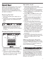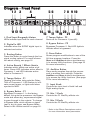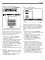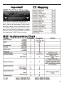
1
MX200
User
Guide
Warranty
This warranty is valid only for the original purchaser and only in the United States.
1. The warranty registration card that accompanies this product must be mailed within 30 days after purchase date
to validate this warranty. Proof-of-purchaseis considered to be the burden of the consumer.
2. Lexicon Professional warrants this product, when bought and used solely within the U.S., to be free from defects
in materials and workmanship under normal use and service.
3. Lexicon Professional’s liability under this warranty is limited to repairing or, at our discretion, replacing defective
materials that show evidence of defect, provided the product is returned to Lexicon professional WITH RETURN
AUTHORIZATION from the factory, where all parts and labor will be covered up to a period of 1 year. A Return
Authorization number must be obtained from Lexicon Professional by telephone. The company shall not be liable
for any consequential damage asa result of the product's use in any circuit or assembly.
4. Lexicon Professional reserves the right to make changes in design or make additions to or improvements upon
this product without incurring any obligation to install the same additions or improvements on products previously
manufactured.
5. The foregoing is in lieu of all other warranties, expressed or implied, and Lexicon Professional neither assumes
nor authorizes any person to assume on its behalf any obligation or liability in connection with the sale of this product. In no event shall Lexicon Professional or its dealers be liable for special or consequential damages or from any
delay in the performance of this warranty due to causes beyond its control.
Quick Start ...............................................................................................................1
About the MX200 .....................................................................................................3
Overview ...........................................................................................................3
Diagram - Front Panel..............................................................................................4
Diagram - Rear Panel ..............................................................................................6
Setup ........................................................................................................................7
Connecting the MX200 .....................................................................................7
Using the MX200 .....................................................................................................10
Loading Programs .............................................................................................10
Editing Programs ...............................................................................................10
Selecting Effects ................................................................................................10
Tap Tempo .........................................................................................................11
The Audition Feature .........................................................................................11
Routing Options.................................................................................................12
Storing Programs...............................................................................................12
Effects Descriptions .................................................................................................13
Reverbs.............................................................................................................13
Delays ...............................................................................................................17
dbx® Dynamics.................................................................................................19
Modulated Effects .............................................................................................20
MX200 Utilities .........................................................................................................23
MIDI Channel ....................................................................................................23
Program AutoLoad ............................................................................................23
Analog / Digital Input Select .............................................................................23
Digital Out Dry Track.........................................................................................24
Stereo and Mono Output Modes ......................................................................24
Factory Program Banks: Serial and Parallel.....................................................24
Bypass Mode Select .........................................................................................25
Factory Reset....................................................................................................25
The MX-Edit Editor/Librarian - Windows..................................................................26
Minimum System Requirements .......................................................................26
Installing the MX-Edit Editor/Librarian Software ...............................................26
Quick Start ........................................................................................................26
The MX-Edit Library ..........................................................................................27
Opening or Creating a Program .......................................................................27
The MX-Edit Program Editor.............................................................................28
Editing a Program .............................................................................................28
Saving a Program .............................................................................................30
Storing a Program.............................................................................................30
Archiving ...........................................................................................................30
The MX-Edit Editor/Librarian - Mac .........................................................................32
Minimum System Requirements .......................................................................32
Installing the MX-Edit Editor/Librarian ..............................................................32
Quick Start ........................................................................................................32
The MX-Edit Program Window .........................................................................32
Editing a Program .............................................................................................33
Quick Access Menu ..........................................................................................34
Using the MX200 as a Hardware Plug-In ................................................................35
Minimum System Requirements .......................................................................35
Installing the MX-Edit VST Hardware Plug-In...................................................35
Connecting the MX200 .....................................................................................35
Software Configuration .....................................................................................36
Using the MX200 Plug-In Window ....................................................................36
Controls.............................................................................................................36
MIDI Port Error Message ..................................................................................37
CC Mapping .............................................................................................................37
MIDI Implementation Chart ......................................................................................37
Specifications ...........................................................................................................38
Appendix ..................................................................................................................39
Program List.............................................................................................................40
Quick Start
Ideally, you should read this entire manual
before using the MX200. But, if you just
can’t wait to get started, this section
explains how to set up a simple parallel
connection (using the MX200 with a mixer)
and select a program.
Powering the Unit
1. Plug the included power supply into an
A/C outlet.
2. Connect the Power Supply to the Power
Jack connection on the MX200’s back
panel.
Power
3. When the MX200 first powers up, the
Audition button quickly flashes for a
moment. This indicates that the software
is loading.
Standard Parallel Connection
Aux
Return 1
Aux
Return 2
Aux
Send 1
Set Audio Levels
1. Set the gain on the mixer’s input
channel appropriate to the source (vocal
mic, guitar, keyboard, etc.).
2. Set the Aux Master level (if provided on
your console) to the 12 o’clock position.
3. Set the Input level on the MX200 to the
12 o’clock position.
4. Set the Mix 1 and Mix 2 knobs on the
MX200 to their full clockwise position.
(Wet).
5. Provide source signal (by speaking or
singing into the mic, playing guitar,
keyboard, etc.) on the selected mixer
channel.
6. Turn up the Aux Send level on the
channel corresponding to the Post-fader
send (Aux 1 in this example) that the
MX200 is connected to until the Red
Input LEDs light only occasionally. If the
red Input LEDs stay lit, too much signal
is being sent to the MX200; reduce the
Aux Master or Aux Send on the mixer.
7. Turn up the Aux Return to the 12 o’clock
position, or stereo line input faders to
the 0dB position, if you used that
connection.
8. To increase or decrease the amount of
effect on the signal, adjust the Aux Send
level on the channel that you want
affected.
Select and Load a Program
Turn the Program Select knob to choose
a program. The display flashes the number
of the program to be loaded. Press the
knob to load the program.
Program Select knob
1. Connect the mixer’s Post Fader Aux
Send output to the MX200’s Left (Mono)
input.
2. Connect the MX200 Left and Right
outputs to a stereo Aux Return input on
the mixer (or a stereo line input, or two
adjacent line inputs if you like).
Note that the MX200 comes with 99
Factory programs and 99 User programs.
A small dot appears at the bottom right of
the Program Display window, indicating
that the displayed program is a User program. For more information about editing
programs, see page 10.
1
Quick Start
Audition the Effect
Audition Button
The Audition button allows you to preview
the loaded program by playing short digital
samples through the effect processors.
There are five audio samples included in
the MX200, including various drum sounds,
vocal, and guitar. In the factory setting, tapping the Audition button cycles through
the five sounds, but you may want to
repeat a particular sound as you choose or
edit an effect. See page 11 for more information.
2
About the MX200
Overview
The MX200 is a dual-processor, single
rack space multi-effects device designed
with both live sound reinforcement and
home recording in mind. Featuring the
deep, rich reverb algorithms that built the
Lexicon® legend, the MX200 offers
increased versatility with dynamics and
specialty effects—all instantly accessible
via the extremely intuitive front panel.
Either way you use the MX200 – live or in
the studio – you can choose two effects at
once in one of four routing schemes: Dual
Stereo (Parallel), Cascade (Serial), Mono
Split or Dual Mono. The MX200 has 99
carefully crafted Factory programs, and 99
User programs that allow you to create
your own custom effect settings. Front
panel controls include Input Level, Mix 1
and Mix 2 controls, effects Routing button,
independent Tempo and Bypass buttons,
three Parameter knobs for each
Processor, Program Select knob, an
Audition button, and a Store button.
Studio Operation
The MX200 features a USB interface that
lets it function as a “hardware plug-in” –
recognized and functioning within a VSTTM
or Audio Units compatible recording application as a plug-in effect, but still operating
as a dedicated hardware processor. This
unique hardware plug-in feature lets you
add legendary Lexicon effects to your computer-based recordings with full automation
and recall features via an intuitive crossplatform plug-in window without overburdening your CPU.
Live Operation
Those using the MX200 in live applications
will appreciate its intuitive front panel layout. The Active Reverb/Effects Matrix
displays which two of the 32 available
reverbs and effects are active, and all editing functions require only a single button
push or turn of a knob. Dual independent
processor control areas feature dedicated
Effects Select, Tempo, and Bypass buttons plus three Parameter knobs that provide instant access and control over the
most critical parameters for the selected
effect. Parameter change LEDs illuminate
to indicate any changes to the 99 Factory
or User programs. The Audition button
plays one of five digitally recorded audio
samples through the selected effects to
audition their settings without the need for
an external audio source.
3
Diagram - Front Panel
4
12 3
11 12 13
14
1. Dual Input Bargraph Meters
LEDs indicate input level for each channel.
56
15
2. Digital In LED
Indicates when the S/PDIF digital input is
selected and active.
3. Routing Button
Press this button to cycle through the four
signal routing options. For more information about routing, see page 12.
4. Active Reverb / Effects Matrix
Indicates which effects are active at all
times. Green LED indicates active effect in
Processor 1, red LED indicates active
effect in Processor 2.
5. Tempo Button - P1
Tapping this button twice sets the Delay
Time of Processor 1. LED flashes to indicate current tempo, or lights solid when
synched to MIDI.
6. Bypass Button - P1
Bypasses Processor 1. In the factory
default, this puts the processor into Bypass
mode and allows dry, unprocessed signal
to pass through to the outputs. To change
to Bypass Mute, which allows no signal
(wet or dry) to pass, see Bypass Mode
Select in the Utilities section on page 25.
4
16
17
7 8 9 10
18
19
20
21
7. Tempo Button - P2
22
23
Same as for Processor 1 (see #5).
8. Bypass Button - P2
Bypasses Processor 2. Red LED lights to
indicate effect is bypassed.
9. Store Button
Stores program modifications to one of the
99 User program locations. Press the
Store and Audition buttons simultaneously to access Utility functions. (See page 23
for more information.)
10. Audition Button
Plays audio samples through the processors to audition their settings. Press the
Audition and Store buttons simultaneously to access the Utility functions. (See page
23 for more information.)
11. Input Knob
Controls the input level of both Left and
Right analog inputs.
12. Mix 1 Knob
Controls the P1 Wet/Dry effects mix.
13. Mix 2 Knob
Controls the P2 Wet/Dry effects mix.
* Refer to the Effects Descriptions section
for more information about parameters.
14. Effect Select - P1
This button selects the reverb, delay, or
effect to be loaded in Processor 1.
15. Pre Delay Knob - P1
Controls Pre Delay of the reverbs or the
first parameter of the selected delay or
effect in Processor 1.*
16. Decay Knob - P1
Controls Decay of the reverbs or the second parameter of the selected delay or
effect in Processor 1.*
17. Variation - P1
Controls Liveliness or Diffusion (depending
on the reverb selected) or the third parameter of the selected effect in Processor 1.*
18. Effect Select - P2
Same as for Processor 1 (see #14).
Diagram - Front Panel
19. Pre Delay Knob - P2
Same as for Processor 1 (see #15).
20. Decay Knob - P2
Same as for Processor 1 (see #16).
21. Variation - P2
Same as for Processor 1 (see #17).
22. Program Display
2-character LED display indicates which of
the 99 Factory or User programs is loaded.
A small dot appears at the bottom right of
the Program Display window, indicating
that the displayed program is a User program. Also shows Utility settings and
parameter values during editing.
23. Program Select Knob
Navigates through Factory and User programs, as well as Utility functions.
* Refer to the Effects Descriptions section
for more information about parameters.
5
Diagram - Rear Panel
1
2
3
4 5
1. Power Jack
Connect only the included Harman Pro
PS0913B power supply here.
2. Footswitch Input
An optional 2-button footswitch can be
plugged into this TRS jack for independent
Bypass control of P1 and P2. Use the
Lexicon® LEX-DFS or a 2-button footswitch
wired as follows:
Tip
= Bypass 2
Ring
= Bypass 1
Sleeve = Ground
3. MIDI In, Out/Thru
Provides MIDI operation capabilities. Two
5-pin MIDI DIN connectors are available
for MIDI IN and MIDI OUT/THRU. (See
page 37 for MIDI Implementation chart.)
4. USB Port
Provides communication with a computer
for use with MX-EditTM software and MX200
plug-in window using a standard USB
cable. When the MX200 is connected to a
computer via USB, US briefly appears in
the Program Display window.
5. S/PDIF Digital In/Out
Digital input accepts 44.1kHz / 48kHz signals. When the S/PDIF digital input is
selected and active, the Digital In LED on
the front panel lights.
6
6
7
Important: It is recommended that you do
not connect any digital device to the
MX200’s S/PDIF input that transmits at any
other sample rate (such as 96kHz). Doing
so can cause unpredictable performance.
Make sure the device you are connecting
to the MX200’s S/PDIF In is set as the
Clock Master (if that option is available)
and transmitting at a sample rate of
44.1kHz or 48kHz only. As with any other
connection, if you need to unplug the
S/PDIF cable, it is recommended that you
switch to the analog inputs (see Digital
Input Select in the Utility section) or
bypass both processors before disconnecting the cable.
6. Balanced Analog Line Outputs
Left and Right RF-filtered 1/4”
balanced/unbalanced TRS line outputs are
servo-balanced, so no signal loss is
incurred when using unbalanced connections. To use the Left output as a mono
sum of both Left and Right signals, refer
to the Stereo/Mono Output Mode Utility
section on page 24.
7. Balanced Analog Line Inputs
Left and Right active analog 1/4” TRS balanced/unbalanced line inputs. If only a single plug is connected to the Left input, the
signal is split and sent to both the Left and
Right input paths.
Setup
Connecting the MX200
Parallel vs. Serial
The MX200 can be used as both a Parallel
and Serial (in-line) effects processor.
Typically, reverbs and delays are used in
parallel, compressors and de-essers in
serial, and modulated effects can be used
in either configuration, depending on the
desired application.
A Parallel Processor is connected by sending a copy of a signal (such as from an
Aux Send of a mixer channel) to an effects
device (such as the MX200), and the
effected (or wet) signal is returned to the
mixer or amp. It is then blended together
with the original unaffected (dry) signal.
This blend is called the Wet/Dry mix. This
connection is most often used for reverbs,
delays, and some modulated effects (such
as chorus).
A Serial Processor is connected by sending the entire signal through the effects
device and then to an amplifier or mixer,
and is not blended with the unaffected
(dry) signal. This is the type of connection
most often used for a compressor, deesser, equalizer, and many modulated
effects (such as tremolo, vibrato, and
rotary).
The following illustrations show how to
connect the MX200 in both Serial and
Parallel configurations, using some common, real-world examples.
Parallel Connection
Mixer - Mono In/Stereo Out Setup
Aux
Return 1
Aux
Return 2
Aux
Send 1
This setup is the most commonly used
configuration in both live and studio applications.
1. Select routing 2 or 4 using the Routing
button.
2. Connect the mixer’s Post Fader Aux
Send output to the MX200’s Left (Mono)
input.
3. Connect the MX200’s Left and Right
outputs to a stereo Aux Return input on
the mixer (or a stereo line input, or two
adjacent line inputs if you like).
4. Set the gain on the mixer’s input
channel appropriate to the source (vocal
mic, guitar, keyboard, etc.).
5. Set the Aux Master level (if provided on
your console) to the 12 o’clock position.
6. Set the Input on the MX200 to the 12
o’clock position.
7. Set the Mix 1 and Mix 2 knobs on the
MX200 to their full clockwise (Wet)
position.
8. Turn up the Aux Send level on the
channel corresponding to the Postfader Aux Send (Aux 1 in this
example) that the MX200 is connected
to until the red Input Bargraph LEDs
light only occasionally. If the red Input
7
Setup
Bargraph LEDs stay lit, too much
signal is being sent to the MX200;
reduce the Aux Master or Aux send on
the mixer.
9. Turn up the Aux Return to the 12
o’clock position (or line input faders to
the 0db positions, if you used that
connection).
10. To increase or decrease the amount of
effect on the signal, adjust the Aux
Send level on the channel that you
want affected.
Mixer - Dual Mono Setup
Aux
Return 1
Aux
Return 2
Aux
Send 1
Serial Connections
Guitar - Effects Loop Setup
Aux
Send 2
This setup applies to a mixer with two (or
more) Aux Sends and Returns. It utilizes
the two effect sections in the MX200 as
two separate effects with separate mono
outputs, or a common stereo output.
1. Select routing 1 or 4 using the Routing
button.
2. Connect Aux 1 send to the MX200 Left
input.
3. Connect Aux 2 send to the MX200
Right input.
4. Connect the MX200 Left and Right
outputs to the mixer’s Aux returns 1 and
2 for mono, or Stereo Aux L/R returns
for stereo.
5. Set Mix 1 and Mix 2 knobs fully
clockwise (Wet).
6. Set the MX200’s Input knob to the 12
o’clock position.
7. Set the Aux Return levels on the mixer
8
to 12 o’clock.
8. Turn up Aux Sends 1 and 2 on the
mixer for the selected channels so the
red Input Bargraph LEDs only light
occasionally with signal (adjusting the
Input knob on the MX200 may be
necessary).
9. Control the amount of effect using the
Aux Send levels on the selected mixer
channels.
Power Amp
In
Preamp
Out
1. Select routing 2 using the Routing
button (you can always experiment
using other routings).
2. Connect guitar to the amp’s Input.
3. Connect the amp Effects Loop Send or
Preamp Out to the MX200’s Left input.
4. Connect the MX200’s Left output to the
amp’s Effects Loop Return or Power
Amp In.
5. Set Mix 1 and Mix 2 knobs to the 12
o’clock position.
6. Adjust the Input level so the red Input
Bargraph LEDs only light occasionally
with signal.
7. To adjust the effect level, use the Mix 1
and Mix 2 knobs.
Setup
Instrument - In Line Setup
Studio – Digital Setup
S/PDIF Out
S/PDIF In
Stereo
Line Input
This setup utilizes the MX200 as a multieffects processor connected in line from an
instrument to a mixer. It is an ideal setup to
use when your mixer does not have an
Aux Send/Return option built in.
1. Select routing 2 using the Routing
button (you can always experiment
using other routings).
2. Connect a line level signal directly from
your instrument to the MX200 Inputs.
(use Left input for mono signals).
3. Connect the MX200’s Left and Right
outputs to two separate mixer channels
or a stereo line input.
4. Set the MX200’s Input knob to the 12
o’clock position.
5. Set Mix 1 and Mix 2 knobs to 12 o’clock
position.
6. Adjust the Input level so the red Input
Bargraph LEDs only light occasionally
with signal.
7. Adjust the Mix 1 and Mix 2 knobs for
the desired effect mix level.
This setup is ideal if you are using the
MX200 as a hardware plug-in in a digital
recording system. This setup requires that
you are using an I/O device with S/PDIF
In/Out, or a digital mixer with S/PDIF I/O
option.
1. Select routing 2 using the Routing
button. (You can always experiment with
other routings.)
2. Connect the S/PDIF output on your
soundcard, audio interface or mixer to
the S/PDIF In on the MX200.
3. Connect the MX200 S/PDIF Out to
the S/PDIF input on your soundcard,
audio interface or mixer.
4. Make sure the device you are
connecting to the MX200’s S/PDIF In is
set as the Clock Master (if that option is
available) and transmitting at a sample
rate of 44.1kHz or 48kHz only. (Refer to
the documentation for your device
and/or software for proper setup.)
5. Once the MX200 is locked correctly with
your device, the Digital In LED lights.
If the Digital In LED does not light,
check your cables and make sure that
your I/O device is set as Master Clock.
9
Using the MX200
The MX200 is equipped with 99 Factory
programs that combine the 32 reverbs and
effects to cover a wide range of applications. Additionally, there are 99 User program locations in which to store your own
reverb and effects combinations. These
are identical to the Factory programs until
you change them.
Loading Programs
To load a program:
1. Choose a program by rotating the
Program Select knob. The selected
program number flashes in the Program
Display until loaded. A small LED dot
appears in the lower right portion of the
Program Display if a User program is
selected.
2. Press the Program Select knob to
load the program.
If you would like the programs to be loaded
automatically as they are changed with the
Program Select knob, you can enable the
AutoLoad function (see page 23 for more
information).
Editing Programs
After selecting a Factory or User program,
you may find that it needs some modification for a particular application or use. This
may include changing one of the three
Parameter knobs on each processor,
changing the Mix 1 or Mix 2 settings, altering the Routing, changing the delay
Tempo or engaging one of the Bypass
buttons. When any of the Parameter or
Mix knobs are used, a numerical value for
that parameter will briefly appear in the
Program Display while the knob is being
turned. A small LED next to the knob will
illuminate, denoting a change from the
saved value, and the Store button will
light, indicating that the loaded program
has been modified. To retain these
10
changes, you must store them to a User
program location (see Storing Programs).
Knob and button LEDs are green for
Processor 1, and red for Processor 2, to
correspond with their respective LED color
in the Active Reverb/Effects Matrix.
Either Factory or User programs may be
edited, but they may only be stored to a
User program location.
The Parameter knobs have different functions for each reverb and effect. For
detailed descriptions of what each knob
does, refer to the Effects Descriptions
section.
To edit a program:
1. Load a program using the Program
Select knob.
2. Make any of the following adjustments
or changes:
• Select effects with either or both
Effect Select buttons.
• Modify the program with the Pre
Delay, Decay, or Variation knobs.
• Bypass a processor using P1 or P2
Bypass button.
• Change tempo using the P1 or P2
Tempo button.
• Adjust the Wet/Dry mix for either or both
processors with the Mix 1 and Mix 2
knobs.
• Change effect routings with the Routing
button.
Selecting Effects
The MX200 features 16 classic Lexicon®
reverb algorithms, six types of delay, eight
modulated/pitch effects, and two dbx®
dynamics algorithms.
To select an effect, press the P1 or P2
Effect Select buttons up or down.
The Audition Feature
Effect Select
An LED lights next to the selected reverb
or effect label in the Active
Reverb/Effects Matrix (green LED for P1,
red for P2).
Active Reverb/Effects Matrix
The Effect Select control is cyclical,
meaning if Effect Select is pressed up
when Small Hall is active, Detune will be
the next selected effect. Similarly, if Detune
is active, and Effect Select is pressed
down, the effect will change to Small Hall.
Tap Tempo
Tap tempo can be used to match the delay
times to synchronize with the music. The
Tempo button LED flashes when a delay is
loaded. To set tempo from the front panel,
press the Tempo button twice in time with
the music. The LED will flash at a rate that
corresponds to the new tempo.
MX200 can also use MIDI Sync to set the
tempo of delays. When MX200 detects
MIDI Sync present at the MIDI In, the
Tempo LEDs light constantly to indicate
that tempo is set via MIDI Sync.
Changes made to tempo with the Tempo
button are considered program edits, and
cause the Store button LED to light.
The Audition feature provides 5 digitally
recorded audio samples that are played
back through MX200’s processors at the
touch of a button. This lets you preview the
selected program and dial in reverb or
effects settings without the need for an
external audio source.
In the default setting, each tap of the
Audition button plays the next sample. To
play a single sample repeatedly, change
the Audition options.
To change Audition options:
1. Press and hold the Audition button. The
LED flashes, and the Program
Display alternately displays AU
and AL.
2. Turn the Program Select knob to
select the individual sample you want to
hear when you press the Audition
button.
The samples are:
AL - Audition All Samples. Each time
the Audition button is pressed, the
next sample is played.
A1 - Drum Stick Click
A2 - Snare Drum
A3 - Kick Drum
A4 - Female Vocal “Doo”
A5 - Acoustic Guitar Arpeggio
3. Press the Store button to save the new
Audition setup
The Audition button now plays the selected sample each time it is pressed. The
Audition sample is a global setting, and is
not saved with presets.
11
Using the MX200
Routing Options
The MX200’s powerful Dual Processor
design and four signal routing options
allow you to use it as two independent
effects processors, or combine the reverbs
and effects for a nearly limitless palette of
complex sounds.
1. Dual Mono
This routing option sends the Left and
Right input signals through Processor 1
and Processor 2 respectively. Each signal
is then routed to its respective output, completely independent from the other.
2. Cascade
Left and Right input signals are sent first
through Processor 1, then through
Processor 2, then routed as a stereo signal
to their respective outputs.
3. Dual Stereo (Parallel)
Left and Right input signals are sent
through both processors independently.
The output signals of both processors are
then mixed together, and routed to both the
outputs as a single stereo signal.
4. Mono Split
Left input signal is sent through Processor
1, while the Right input signal is sent
through Processor 2. The output signals of
both processors are then mixed together,
and routed to both the outputs as a single
stereo signal.
12
Storing Programs
Once you have edited a program to your
liking, you can store these edits into a User
program memory location. To store a program, follow these steps:
1. Press the Store button once. ST
appears briefly in the Program Display,
followed by the flashing User program
number (indicated by the small dot over
User Program being lit).
2. Use the Program Select knob to
select a User program location to
store your edits.
3. Press the Store button again to
complete the procedure.
To return to the program without storing
changes, press any other button on the
front panel.
Effects Descriptions
The MX200 effects come in four varieties:
Stereo, Mono In/Stereo Out, Mono (Wet
only), and Stereo (Wet only). When using
Wet only effects, turn the processors Mix
knob fully clockwise.
Reverbs
Reverberation (or “reverb” for short) is the
complex effect created by the way we perceive sound in an enclosed space. When
sound waves encounter an object or
boundary, they don’t just stop. Some of the
sound is absorbed by the object, but most
of the sound is reflected or is diffused. In
an enclosed space, reverb is dependent on
many features of that space, including the
size, shape and the type of materials that
line the walls. Even with closed eyes, a listener can easily tell the difference between
a closet, a locker room and a large auditorium. Reverb is a natural component of the
acoustic experience, and most people feel
that something is missing without it.
Hall Reverbs
Small Hall
Large Hall
Vocal Hall
Drum Hall
Stereo
A Hall is designed to emulate the acoustics
of a concert hall – a space large enough to
contain an orchestra and an audience.
Because of the size and characteristics,
Halls are the most natural-sounding
reverbs, designed to remain “behind” the
direct sound – adding ambience and
space, but leaving the source unchanged.
This effect has a relatively low initial echo
density which builds up gradually over
time. Vocal Hall and Drum Hall reverbs
are specifically tailored for those uses.
Vocal Hall has as lower overall diffusion
which works well with program material
that has softer initial transients like a voice.
Drum Hall has a higher diffusion setting
which is necessary to smooth out faster
transient signals found in drums and percussion instruments. In addition to general
instrumental and vocal applications, the
Hall program is a good choice for giving
separately recorded tracks the sense of
belonging to the same performance.
13
Effects Descriptions - Reverbs
Plate Reverbs
Stereo
Small Plate
Large Plate
Vocal Plate
Drum Plate
A Plate reverb is a large, thin sheet of
metal suspended upright under tension on
springs. Transducers attached to the plate
transmit a signal that makes the plate
vibrate, causing sounds to appear to be
occurring in a large, open space. The
Plates in the MX200 model the sound of
metal plates with high initial diffusion and a
relatively bright, colored sound. Plate
reverbs are designed to be heard as part
of the music, mellowing and thickening the
initial sound. Plate reverbs are often used
to enhance popular music, particularly percussion.
Room Reverb
Stereo
Room produces an excellent simulation of
a very small room which is useful for dialog
and voiceover applications. Room is also
practical when used judiciously for fattening up high energy signals like electric guitar amp recordings.
Chamber Reverb
Stereo
Historically, recording studio chambers
were oddly shaped rooms with a loudspeaker and set of microphones to collect
ambience in various parts of the room.
Chamber programs produce even, relatively dimensionless reverberation with little
color change as sound decays. The initial
diffusion is similar to the Hall programs.
However, the sense of size and space is
much less obvious. This characteristic,
coupled with the low color of the decay tail,
makes these programs useful on a wide
range of material - especially the spoken
voice, to which Chamber programs add a
noticeable increase in loudness with low
color.
14
Gated Reverb
Mono In/Stereo Out
Gated reverb is created by feeding a
reverb, such as a metal plate, through a
gate device. Decay Time is set to instant,
while Hold Time varies duration and sound.
The Gated reverb provides a fairly constant sound with no decay until the reverb
is cut off abruptly. This program works well
on percussion — particularly on snare and
toms; be sure to experiment with other
sound sources as well.
Reverse Reverb
Mono In/Stereo Out
Reverse reverb works in the opposite
fashion from normal reverb. Whereas a
normal reverb has the loudest series of
reflections heard first that then become
quieter over time, the Reverse reverb has
the softest reflections (essentially the tail of
the reverb) heard first, and then grows
louder over time until they abruptly cut off.
Ambience Reverb
Stereo
Studio Reverb
Stereo
Ambience is used to simulate the effect of
a small or medium sized room without
noticeable decay. It is often used for voice,
guitar or percussion.
Much like Room reverb, Studio produces
an excellent simulation of smaller, wellcontrolled acoustic spaces, characteristic
of the main performance areas in recording
studios. Studio is also useful with dialog
and voiceover applications as well as individual instrument and electric guitar tracks.
Effects Descriptions - Reverbs
Arena Reverb
Stereo
Arena reverb emulates a huge physical
space such as an indoor sports venue or
stadium. The characteristics of Arena
reverb are long secondary reflection times
and a reduced amount of high frequency
content. Arena is a mostly mid- and lowfrequency dominant reverb, and is an ideal
selection for “special effect” type applications that require extremely long reverb
times. It is not a good choice for a very
busy mix, since it can reduce intelligibility.
Spring Reverb
Mono In/Stereo Out
A Spring reverb is created by a pair of
piezoelectric crystals—one acting as a
speaker and the other acting as a microphone—connected by a simple set of
springs. The characteristic ‘boing’ of a
spring is an important component of many
classic rock and rockabilly guitar sounds.
Reverb Controls
Pre Delay
Creates an additional time delay between
the source signal and the onset of reverberation. This control is not intended to
precisely mimic the time delays in natural
spaces, as the build-up of reverberation is
gradual, and the initial time gap is usually
relatively short. For the most natural effect,
the Pre Delay values should be set in the
range of 10-25 milliseconds. However, if a
mix is very busy or overly cluttered,
increasing the Pre Delay time may help
clarify it, and set each instrument apart
from each other.
Decay
beration times which are usually associated with larger acoustical environments, but
can decrease intelligibility. Lower settings
shorten reverb times and should be used
when a smaller apparent space or a more
subtle effect is desired.
Liveliness
Adjusts the amount of high frequency content in the reverberation tails. Higher settings increase high frequency response,
creating brighter reverbs; lower settings
create darker reverbs with more bass frequency emphasis.
Diffusion
Controls the initial echo density. High settings of Diffusion result in high initial echo
density, and low settings cause low initial
density. In a real-world situation, irregular
walls cause high diffusion, while large flat
walls cause low diffusion. For drums and
percussion, try using higher Diffusion settings.
Shape
This control helps give a sense of both
room shape and room size. Low values for
Shape keep the majority of sound energy
in the early part of the reverb tail. High values move the energy to later in the reverb,
and are helpful in creating the sense of a
strong rear wall or “backslap.
Boing
This is a unique parameter to the Spring
reverb, designed to increase or decrease
the amount of spring rattle that is a physical characteristic of spring tank reverbs.
Controls the amount of time the reverb can
be heard. Higher settings increase rever-
15
Reverb Control Values
Note: Values of 0 – 100 are displayed as 0 – 00 (100 is displayed as 00 in the Program
Display). Values of greater than 100 are shown with a decimal between the digits, i.e.
115 displayed as 1.5, 150 displayed as 5.0, and 200 is displayed as 0.0.
16
Delays
Delays repeat a sound a short time after it
first occurs. Delay becomes echo when the
output is fed back into the input (feedback).
This turns a single repeat into a series of
repeats, each a little softer than the last.
Studio Delay
Stereo
The Studio Delay features up to 2.5 seconds of stereo delay and offers a built-in
ducker that attenuates the delay output
whenever signal is present at the input.
This can be used to keep the original signal from being muddied up by delay
repeats.
Digital Delay
Mono In/Stereo Out
Tape Delay
Mono In/Stereo Out
The Digital Delay is the cleanest, most
accurate of the delay programs, with up to
5 seconds of mono delay and the built-in
ducking feature.
In the days before digital, delays were created using a special tape recorder in which
the magnetic recording tape was looped,
with closely-spaced recording and playback heads. The delay effect was created
by the tape moving in the space between
the record and playback heads – while
delay time was adjusted by changing the
speed of the tape loop. Although very
musical-sounding, wow and flutter combined with a significant loss of high frequencies, and to some extent also low frequencies, are all elements commonly associated with tape recordings. The Tape
Delay offers up to 5 seconds of mono
delay.
Pong Delay
Mono In /Stereo Out
This delay effect pans the delay repeats
from left to right, while the input signal
remains at its original (center) position.
Pong Delay offers up to 5 seconds of
mono delay time.
Modulated Delay
Stereo
The Modulated Delay is enhanced by an
LFO (low frequency oscillator) that produces a chorusing effect on the delay
repeats. This is a great delay for guitar and
instrument passages that need that “special something.” The Modulated Delay
features up to 2.5 seconds of stereo modulated delay.
Reverse Delay
Mono In/Stereo Out
This delay effect emulates the old studio
trick of flipping a tape over, playing it backwards through a tape delay, and recording
the effect. The delays “build up” from softer
to louder – creating the sensation that the
delays come before the signal. Very cool
when used judiciously. Up to 5 seconds of
mono delay time are available.
Delay Controls
Time Range
Controls the length of the delay relative to
Tap Tempo. At the 12 o’clock position,
delay repeats are synchronous with the
Tempo light (represented by a Quarter
Note); lower values create faster repeats,
higher values increase the time between
repeats. Range 0-72. See Appendix on
page 39 for exact note values.
Feedback
Controls the number of delay repeats by
feeding the delay output signal back into
the delay input. This creates a series of
delay repeats, each slightly attenuated until
they become inaudible. Higher settings
create more repeats; lower settings reduce
the number of repeats. When this knob is
turned fully clockwise, it engages Repeat
Hold – delay repeats play back in an infinite loop, but no further input signal is
introduced into the delay effect. Repeat
Hold is available only on Studio, Digital
and Pong Delay.
17
Effects Descriptions - Delays
Ducker Threshold
MX200’s Studio and Digital delays offer a
“ducking” feature, which causes the delay
repeats to attenuate (or get softer) by -6dB
when live (or input) signal is present. This
allows the delay to remain as an effect,
and not clash with the original signal. The
higher this value is set, the louder an input
signal must be for the ducking to take
place.
Smear
This parameter controls the amount of
“smear,” or signal degradation and frequency loss. Particularly evident in the
Tape Delay, the higher the setting, the
more each delay repeat loses intelligibility
compared to the original signal.
Tap Ratio
Tap Ratio sets the length between the first
and second tap repeats of the Pong
Delay. With this control set at 12 o’clock,
Delay Control Values
repeats are evenly alternated between left
and right channels. As this knob is turned
counter-clockwise, the first tap occurs earlier and the second tap occurs later than
they did at the 12 o’clock position. When
the knob is turned clockwise, the first tap
occurs later and the second tap occurs
earlier.
Depth
This controls the intensity of modulation, or
“depth” in the Modulated Delay. Lower
settings produce a more subtle effect,
while higher values give a more “seasick”
feeling.
Tempo Button
Tapping this button twice sets the delay
times. The Tempo button LED flashes the
tempo tapped in, and delay taps will be
synchronized to the flashing LED. Use the
Time Range knob to increase or decrease
delay times after tapping in a tempo.
Note: When Feedback is turned past 99, the value displays as rh to indicate Repeat
Hold. (Studio, Digital, and Pong delays only.)
18
dbx® Dynamics
De-Esser
Mono (Wet only)
A De-Esser is a type of compressor used
to control specific frequencies. Excessive
sibilance, or the “s” sounds, can be tamed
by applying this effect.
De-Esser Controls
Knob 1: Compression Ratio
amount determined by the Ratio. For
example, if the threshold is set to -12dB,
and the ratio set to 4:1, then when signal
exceeds -12dB, the signal level above that
amount only increases by 1dB to every
4dB of signal level above -12dB. In this
case, an incoming signal of -4dB (which is
8dB above the threshold) would result in
an output signal of -10dB, or 2dB higher
than the threshold level, since the 4:1 compression ratio only allowed 2dB more output, based on the 8dB increase above the
-12dB threshold.
Determines the amount of compression,
from 1:1 (no effect) to Infinity:1 (complete
limiting).
Knob 2: Frequency Range
Selects the frequency range of compression in 40 discrete steps from 1600Hz to
10kHz (the most common frequencies in
which excessive sibilance occurs).
Knob 3: Bandwidth (Q)
Controls the bandwidth or “Quality” (Q) of
frequency range. The higher the selected
value, the tighter the bandwidth, and less
apparent the de-essing effect is.
Incremental in six steps from 1/4 Octave
(0) to 1/24th Octave (5). See Appendix on
page 39 for bandwidth values.
Compressor
Mono (Wet only)
A compressor is used to control the
dynamic range of a signal. Typically used
to tighten bass or drum tracks, or to control
a vocal passage, a compressor is a very
useful but often misunderstood tool. To better use the Compressor in the MX200, a
bit of understanding about compression is
helpful.
When a signal level crosses the
Threshold level, the compressor then
reduces the amount of output level by an
Because the resulting output is less than
the original signal, a third control, Makeup
Gain compensates for this loss of level,
but with less dynamic range, or the difference between the softest and loudest parts
of the signal.
Compressor Controls
Knob 1: Threshold
Determines the threshold above which
compression begins, incrementally
between -70dB and 0dB (FS).
Knob 2: Compression Ratio
Selects the compression ratio, from 1:1 (no
effect) to Infinity:1 (or complete limiting).
Knob 3: Makeup Gain
Increases the output level to compensate
for signal attenuation during compression.
Incremental between 0dB (no gain) to
+12dB.
19
Modulated Effects
Chorus
Stereo
Chorus creates a lush, full sound by combining two or more signals together where
one is unaffected and the other signals
vary in pitch very slightly over time.
Chorus is commonly used to fatten up
tracks and to add body to guitars without
coloring the original tone. Chorus can also
be used with discretion to thicken a vocal
track.
Chorus Controls
Speed
Controls the modulation rate of the Chorus
effect. Lower settings are subtle, while
higher values are much more pronounced.
Depth
Controls the amount of pitch shifting for
each voice. Lower settings provide subtle
thickening and warmth to a track, while
higher settings give a more pronounced,
multi-voice effect.
Voices
Controls the number of additional Chorus
voices. Up to 8 voices can be added, continuously variable in 100 individual steps.
Flanger
Stereo
This effect was originally created by simultaneously recording and playing back two
identical programs on two tape recorders,
then using hand pressure against the
flange of the tape reels to slow down first
one machine, then the other. The result
was a series of changing phase cancellations and reinforcements, with characteristic swishing, tunneling, and fading sounds.
20
Flanger Controls
Knob 1: Speed
Controls the modulation rate of the
Flanger effect.
Knob 2: Depth
Controls the intensity of the Flanger effect.
Lower settings provide a slight “whooshing”
sound while higher settings provide a
much more dramatic “jet airplane” sound.
Knob 3: Regeneration
This knob controls the amount of modulated signal being fed back into the input, creating feedback. Higher amounts add a
metallic resonance to the signal.
Phaser
Stereo
The Phaser automatically moves frequency notches up and down the spectrum of
the signal by means of a low frequency
oscillator (LFO), creating an oscillating
“comb-filter” type effect. This effect is very
userful on keyboards (especially pad presets) and guitars.
Phaser Controls
Knob 1: Speed
Controls the modulation rate of the Phaser
effect.
Knob 2: Depth
Controls the intensity of the Phaser effect.
Knob 3: Regeneration
This knob controls the amount of modulat-
Effects Descriptions - Modulated Effects
ed signal being fed back into the input, creating feedback. Higher amounts add more
resonance to the effect signal.
Tremolo/Pan
Stereo (Wet only)
Tremolo and Panner create rhythmic
changes in signal amplitude. Tremolo
affects both channel’s amplitude simultaneously, while the Panner affects the amplitude of each channel in an alternating
manner.
Tremolo/Pan Controls
Knob 1: Speed
Controls the modulation rate of the
Tremolo/Panner.
Knob 2: Depth
The Rotary effect is modeled after a
Leslie-style cabinet. The input signal is split
into high and low-frequency bands. The
rotation effect is created by a synchronized
combination of pitch shifting, tremolo, and
panning. Like the physical cabinet, the high
(horn) and low (rotor) frequencies are
“spun” in opposite directions. Horn and
rotor speeds are independent, and
designed with acceleration and deceleration characteristics to simulate the inertia
of the original mechanical elements.
A virtual requirement for organ music,
Rotary also sounds remarkable with guitar
and electric piano rhythm parts. In fact,
these programs are great alternatives to
the Chorus and Tremolo effects for any
sound source.
Controls the intensity of the volume amplitude change.
Rotary Controls
Controls whether the amplitude change
occurs in both channels simultaneously
(Tremolo) or alternates between channels
(Panner).
Knob 2: Doppler
Knob 3: Phase
Rotary
Mono (Wet only)
Rotary speaker cabinets were designed to
provide a majestic vibrato/choir effect for
electronic theater and church organs. The
most well known rotary speaker is the
Leslie™ Model 122, which has two counter-rotating elements: a high-frequency horn
and a low-frequency rotor with slow and
fast speeds. The sound generated as the
spinning elements change speed is truly
magical. The swirling, spacious effect is
difficult to describe – but clearly recognizable.
Knob 1: Speed
Controls the modulation rate of both rotary
speakers. The lower frequencies rotate at
a slower speed than the high frequencies.
Increases or decreases the Doppler pitch
effect that is created by the physics of a
rotating speaker.
Knob 3: Stereo Spread
Increases or decreases the stereo imaging
of the Rotary effect.
Vibrato
Stereo (Wet only)
Vibrato is obtained by smoothly varying
the pitch of the signal just sharp and flat of
the original at a determined rate.
21
Effects Descriptions - dbx® Dynamics
Knob 3: Cutoff Frequency
This controls the cutoff frequency of the
low pass filter. Lower settings roll off high
frequency response.
Vibrato Controls
Knob 1: Speed
Controls the modulation rate of Vibrato.
Knob 2: Depth
Controls the maximum amount of pitch
shift. Lower settings result in a mere “warble,” while higher settings produce a more
exaggerated “wow” sound.
Knob 3: Phase
Detune
Stereo
Detune adds a slightly pitch-shifted version
of the original source, thickening the
sound. This creates a particularly effective
simulation of “double-tracking.” This effect
is also a great alternative to the Chorus
effect, adding the richness of a chorus
without the audible sweep caused by the
chorus rate.
This control sets left and right channel
waveforms out of phase, resulting in a leftto-right panning motion.
Pitch Shift
Stereo
This effect shifts the frequency spectrum of
the input signal. Altering the pitch of a
sound produces a wide range effects from subtle detunes to full interval shifts up
or down a two octave range. The MX200’s
Pitch Shift effect is a chromatic shifter,
meaning all notes of the scale are shifted
by the same interval. Pitch Shift is very
useful with guitar tracks, monophonic synth
lines, or where special vocal effects are
needed.
Pitch Shift Controls
Knob 1: Shift Amount
Determines the amount of pitch shifting.
Range is 0-24 semitones (2 octaves).
Knob 2: Down/Up Shift
Determines whether the pitch shifting is up
or down from the original signal.
22
Detune Controls
Knob 1: Left Shift Amount
Determines the detune amount of the Left
input, from -24 cents to +24 cents.
Knob 2: Right Shift Amount
Determines the detune amount of the
Right input, from -24 cents to +24 cents.
Knob 3: Stereo Spread
Higher values increase the perceived distance of the detuned voices in the stereo
field.
MX200 Utilities
The MX200 has several global functions
that can be customized to meet your
needs. These functions are MIDI Channel
Select, Program AutoLoad enable, Dry
Track to digital output, Analog/Digital
Input Select, and Factory Reset. To
access these Utility functions, press and
hold both the Store and Audition buttons
simultaneously until the Audition button
LED begins to flash. The Program Display
reads Ut to indicate that you are in Utility
mode rather than Program mode.
Navigation between Utility functions is controlled by pressing the Audition button;
changes are made by turning the Program
Select knob.
MIDI Channel
The MX200 is capable of receiving incoming MIDI Program Change and CC
(Continuous Controller) messages via a
MIDI or USB connection. The MX200 can
be set to receive on any single MIDI channel, all MIDI channels, or can have MIDI
receive disabled.
To select the MIDI channel:
1. Press both the Store and Audition
buttons simultaneously.
2. The first menu displayed when entering
the Utility mode is the MIDI Channel
menu. The Program Display
alternates between Ch and 1 (1 is
the factory default MIDI channel).
3. Use the Program Select knob to
choose the MIDI channel that you want
the MX200 to receive incoming MIDI
Program Change and CC messages on.
The range is 1-16, AL (omni), and OF
(ignores incoming MIDI messages).
4. Press the Store button to save this
change.
Program AutoLoad
From the factory, the MX200 is configured
to have presets loaded manually once they
are selected. This is useful in live applications when a performance requires different programs to be loaded that are not in
adjacent memory locations. Select the program using the Program Select knob and
then press the knob to load it for use. The
previous program remains active until the
new program is loaded. If you would like
the programs to be loaded automatically as
they are changed with the Program Select
knob, you can enable the AutoLoad function.
To enable AutoLoad:
1. Press both the Store and Audition
buttons simultaneously.
2. Press the Audition button repeatedly
until Lo appears in the Program
Display. The Program Display flashes
between Lo and OF, indicating the
AutoLoad feature is disabled.
3. Turn the Program Select knob until the
display reads On to enable AutoLoad.
4. Press the Store button to save this
change.
Analog / Digital Input
Select
The MX200 has both analog and S/PDIF
digital inputs and outputs available. The
S/PDIF digital output is always operational
and any incoming analog signal is
processed and sent to both the analog and
digital outputs. When a digital signal is
received at the S/PDIF digital input from
another device, the MX200 automatically
disables the analog inputs and enables the
digital input to receive signal from the
external device. There are times however,
you may want to leave the digital device
connected but receive signal from the analog inputs.
To enable or disable the digital input:
1. Press both the Store and Audition
23
MX200 Utilities
buttons simultaneously.
2. Press the Audition button repeatedly
until In appears in the Program
Display. The Program Display flashes
betweenIn and dI if the digital input is
selected. If you want to disable the
digital input and use the analog inputs,
turn the Program Select knob until the
Program Display reads An to select the
analog input.
3. Press the Store button to save this
change.
Digital Out Dry Track
The MX200 can send unprocessed digital
audio (Dry Track) out the S/PDIF Digital
Out while monitoring processed audio
through the analog outputs. This is useful
when you want to record a dry performance digitally, but also hear effects processing while you a recording.
Note: The Dry Track feature is only available for signals brought into the MX200 via
the analog inputs. Dry Track has no effect
on signals being received at the S/PDIF In.
Digital in/out signals are processed normally regardless of whether the Dry Track
parameter is enabled or disabled.
To enable Dry Track:
1. Press both the Store and Audition
buttons simultaneously.
2. Press the Audition button repeatedly
until dt appears in the Program
Display. The Program Display flashes
between dt and Of
3. Turn the Program Select knob until the
Program Display reads On to enable
the Dry Track feature.
4. Press the Store button to save this
change.
24
Stereo and Mono Output
Modes
The MX200 outputs can be either Stereo
or Mono depending on your application
needs. When Stereo Output Mode is
selected (MX200’s default Output Mode),
the signals maintain stereo separation as
configured by the Routing button. When
Mono Output Mode is selected, both Left
and Right output signals are summed to
mono and then sent out the Left output.
To select Mono or Stereo Output Modes:
1. Press both the Store and Audition
buttons simultaneously until Ut appears
in the Program Display.
2. Press the Audition button repeatedly
until OP appears in the Program
Display. This is the Output Mode setup
menu. The Program Display
alternately flashes OP and then St
to indicate Stereo Output Mode is
selected.
3. To change the Output Mode to Mono,
turn the Program Select knob until no
appears in the Program Display
indicating Mono Output Mode is now
selected.
4. Press the Store button to save these
changes.
Note: When Mono Output Mode is selected, effects like Panner and Pong Delay will
no longer have left to right animation as
they do when Stereo Output Mode is
selected.
Factory Program Banks:
Serial and Parallel
The MX200 has two sets of Factory program banks: the Parallel bank and Serial
bank. The Parallel processing bank is used
when the MX200 is configured in an
Auxiliary Send/Return setup with a mixer.
The Serial bank is designed for use when
the MX200 will have a signal source (such
as an instrument) connected directly to its
inputs and the MX200’s outputs are connected to a mixer or amplifier input channels. The difference between these two
banks is the way the Mix 1 and Mix 2 controls are set in the Factory programs, providing the proper wet/dry mix for either
application.
Note: The default Factory bank is the
Serial bank. If you plan to use the MX200
as a Parallel device in a mixer Aux
Send/Return setup, select the Parallel
bank of Factory programs.
To select the Parallel bank of Factory programs:
1. Press both the Store and Audition
buttons simultaneously until Ut appears
in the Program Display.
2. Press the Audition button repeatedly
until Fb appears in the Program
Display. This is the Factory Bank
program select menu. The Program
Display alternately flashes Fb
and then SE to indicate the Serial bank
of Factory programs is selected.
3. To select the Parallel bank of Factory
programs, turn the Program Select
knob until PA appears in the Program
Display.
4. Press the Store button to save these
changes.
Bypass Mode Select
From the factory, MX200 is configured so
that engaging the Bypass button on P1 or
P2 causes that processor to go into
Bypass mode, allowing dry, unprocessed
signal to pass through unaffected. There
are cases when you may want to have this
button mute the output altogether, allowing
neither wet nor dry signal to pass. Note
that this configuration should only be used
for Routing options 1, 3 and 4; placing
either Processor in Bypass (mute) when
MX200 Utilities
Routing 2 (Cascade) is selected will cause
the MX200 to have no output, as the entire
signal is muted by the Processor placed in
Bypass.
To change this setting:
1. Press both the Store and Audition
buttons simultaneously.
2. Press the Audition button repeatedly
until bP appears in the Program
Display. The Program Display flashes
between bP and dr (indicating dry
signal).
3. Turn the Program Select knob until the
display reads no (or no signal).
4. Press the Store button to save this
change.
Factory Reset
Use this utility if you want to erase all User
program data and restore the MX200 to its
factory state.
To perform a Factory Reset:
1. Press both the Store and Audition
buttons simultaneously.
2. Press the Audition button repeatedly
until Fr appears in the Program
Display
3. To restore the MX200 to its factory state,
press the Store button. The Store
button begins to flash.
Warning: Pressing and holding the Store
button again at this time resets all Utility
menus to their factory defaults and permanently erases all User programs! This will
not affect the Factory programs or any programs saved to your computer using the
MX-Edit Librarian software.
4. Press and hold the Store button to
complete the reset procedure. The
display flashes rs to indicate the
Factory Reset was successful.
25
The MX-EditTM Editor/Librarian - Windows
The included MX-Edit Editor/Librarian software lets you create, edit, compare, save
and load reverb and effects programs for
use with your MX200 on your Windows®
computer. While the MX200 has 99 User
program locations, you can create and
save as many programs you like on your
computer, and load them into your MX200
via a USB or MIDI connection at any time.
Minimum System Requirements
Files->Lexicon->MX-Edit->Reinstall
Drivers, and follow the installation prompts.
Quick Start
When you first open MX-Edit, you will see
the MX-Edit Library on the left side of the
MX-Edit window, with the MX200 icon at
the top of the Library.
Before installing the MX-Edit
Editor/Librarian software, make sure that
your computer meets the following minimum requirements:
• Pentium-III, 500MHz or better.
• Windows XP, Service Pack 2 or higher.
Installing the MX-Edit
Editor/Librarian Software
To install the included MX-Edit
Editor/Librarian software in Windows XP,
insert the provided disc into your computer’s CD-ROM drive. You will be guided
through the installation process – just follow the on-screen instructions and
prompts. Note that you will be prompted to
connect the MX200 via the USB port during the installation process. In order for
your computer to recognize the MX200
connection, it is necessary to have the
MX200 powered on and connected via a
standard USB cable.
Important: If you plug your MX200 into a
USB port other than the one used during
the installation of MX-Edit software and
drivers, you may need to run the USB driver installer again. For your convenience, a
shortcut to the USB driver installer is
added to the Start menu during the MXEdit software installation. If you need to
reinstall the drivers, click Start->Program
26
Double-click the MX200 icon to expand the
Library, then double-click the Factory or
User icons to see the Factory or User program lists. The Factory list will always be
the same, as Factory programs cannot be
changed; the User program list will represent the programs currently residing in the
User program locations 1-99 in your
MX200 hardware.
Double-click a program name to open it in
the editor. An instance of the MX-Edit
Program Editor appears, with the selected
program’s name in the Title Bar and
Program Name field. The program settings
are also reflected in the Parameter knobs
and buttons in the Program Editor window.
Opening or Creating a
Program
The selected program is now loaded in
your MX200 as well, and can be previewed
using the Audition button on the MX200’s
front panel. Any changes made in the MXEdit Program Editor window will also occur
simultaneously on the MX200 hardware.
The MX-EditTM Library
The MX-Edit Library contains the 99
Factory and 99 User programs that are
currently loaded in your MX200. When you
first open MX-Edit, it communicates via
USB (or MIDI) with the MX200 hardware,
and populates the Library with all the information about each of the Factory and User
programs stored in MX200’s physical
memory.
To view programs in the Library window,
double-click on the MX200 icon in the
upper left corner, then double-click the
Factory or User icon to expand the Library
and see the Factory or User program lists.
The Factory list is always the same, as
Factory programs cannot be overwritten;
the User program list represents the 99
User programs currently saved in your
MX200 hardware.
To open a program, choose one of the following:
• To open a Factory or User
program from the MX-Edit Library,
double click on that program number in
the Library window.
• To open a program that has been saved
to your computer (but doesn’t appear in
the MX-Edit Library), click File and
select Open Program. By default,
the Open dialog looks in the My
Documents folder (or the last folder that
a program was opened from). Doubleclick the program to load it.
• To open a program with the currently
active settings from the MX200, select
Open Current Program in the
Device menu. This will retrieve all
current settings from the MX200’s front
panel, and display those settings in the
Program Editor window.
To create a new, default program, click File
and select New Program. The default program is a template that you can use as a
good generic starting point when you want
to create your own program from scratch. It
is stored in a file named Default in the MXEdit installation folder (normally
C:\Program Files\Lexicon\MX-Edit). Initially,
27
The MX-Edit Editor/Librarian - Windows
this program is a basic clean sound.
However, you can create your own default
program by overwriting the Default file in
the MX-Edit directory with the program of
your choice.
The MX-EditTM Program
Editor
The MX-Edit Program Editor lets you
quickly and easily view, compare and edit
any program stored in the MX200, or programs saved to your computer.
and buttons, and are loaded into the
MX200 hardware. The program (and any
edits you make) can be previewed at any
time by using the Audition button on the
MX200 front panel.
You can have multiple Program Editors
open at once, but only the currently selected window is active. In other words,
MX200 processes the settings of the active
Program Editor, and you only hear the settings of the active (selected) Program
Editor window.
Editing a Program
Signal Routing Options
MX-Edit gives you all the same control and
functionality as the MX200 front panel, with
the exception of Input control, Audition,
and Utility functions. You’ll also see that
the Routing button has been replaced by
a pull-down menu, as have the two Effect
Select buttons. The Active
Reverb/Effects Matrix and Program
Display have been replaced by the Title
Bar and values above the Parameter
adjust knobs.
With these minor differences, the Program
Editor works just like the MX200’s front
panel – and all changes that you make in
the active Program Editor window are
reflected in real-time on the MX200. MXEdit and the MX200 are fully interactive, so
any changes made on the MX200’s front
panel are reflected in real-time in the active
MX-Edit Program Editor window as well.
When you open a program, an instance of
the MX-Edit Program Editor appears, with
the selected program’s name in Program
Name field. The settings of the loaded program are reflected in the Parameter knobs
28
To change MX200’s Routing, left click on
the Routing button in the Input/Routing
control area. A list of the MX200’s four
Routing options appears, with a check
mark next to the currently selected routing.
Highlight an item in the list and left click to
select and load it. A routing diagram will
appear next to the Routing button, and the
routing name will be shown in the button.
Reverb/Effect Selection Buttons
To change a reverb or effect in Processor 1
or Processor 2, left click on the
Reverb/Effect Select button in P1 or P2
control area. A list of the MX200’s 32
reverbs and effects appears, with a check
mark next to the currently selected reverb
or effect. Highlight an item in the list and
left click to select and load it. Notice that
the reverb or effect name now appears in
the Reverb/Effect Select button, and the
Parameter knobs in MX-Edit change posi-
The MX-Edit Editor/Librarian - Windows
tion depending on the default values for
the selected reverb or effect.
Adjusting Knobs
To make editing in MX-Edit easy and intuitive, there are three ways to adjust knobs
in MX-Edit:
Mouse - Circular
Place the cursor at the outer (shadowed)
edge of a knob, then click and hold the left
mouse button. The white indicator line on
the knob jumps to the mouse cursor’s position, and follows the cursor as it moves
around the circumference of the knob. To
make fine adjustments, continue to hold
the left mouse button down and move the
cursor away from the knob; the white line
still follows the cursor, no matter how far
away it is from the knob.
Mouse – Up / Down
Move the mouse cursor to the center of a
knob; the knob is highlighted, and the cursor changes to a double-headed arrow,
pointing up and down. Click and hold the
left mouse button, causing the cursor to
disappear. Move the mouse up to turn the
knob higher, or move the mouse down to
turn the knob lower. For very fast edits,
press and hold the Ctrl key on your computer keyboard while moving the mouse;
this multiplies the adjusted value by a factor of 10.
Arrow Keys
Highlight, then left-click on a knob to select
it. Use the up (or right) arrow key to turn
the knob higher and increase the value;
use the down (or left) arrow key to turn the
knob lower, decreasing the value. This is a
very effective method for making small
adjustments to fine-tune your settings. For
faster modifications, press and hold the
Ctrl key on your computer keyboard while
pressing an arrow key to multiply each
adjustment by a factor of 10.
Tempo
If one of the MX200’s six delays is selected, the Tempo button in that processor
becomes active, and begins to flash at the
rate displayed above the Time Range
knob. The tempo value is shown in milliseconds (ms), and a quarter-note appears
next to the displayed tempo. When the
Time Range parameter is adjusted, exact
divisions of time in milliseconds relative to
the flashing Tempo rate will cause a note
value to be displayed next to the time, e.g.
16th note, dotted-8th note, etc. The Tempo
button will continue to flash at the originally
selected tempo, but the delay taps will
occur at the rate displayed in the Time
Range value.
To change the tempo value, simply place
the mouse cursor over the Tempo button,
and left-click twice to tap the tempo, just as
you would on the MX200 front panel. The
Tempo buttons on MX200 and in the
Program Editor window now flash at the
new tempo.
If something other than one of the six
delays is loaded in the processor, the
Tempo button is grayed out and inactive.
Bypass
To engage the Bypass button (and turn off
the selected effect), place the mouse cursor over the Bypass button, and left-click
to bypass that processor. Note that the
Bypass buttons on both the MX200 front
panel and the Program Editor illuminate to
indicate the selected processor is
bypassed.
Program Name
To create or change a program’s name,
simply left click once anywhere in the
Program Name field. The program name
will be highlighted; type the new name into
the Title Bar. The program name in the
Header area will not change until the program has been saved.
29
The MX-Edit Editor/Librarian - Windows
Saving a Program
If you make any changes to a program, an
asterisk (*) will appear next to the program
name in the Title Bar of the Program
Editor. The LED associated with the corresponding knob or button and the Store button on the MX200’s front panel also illuminates, indicating a change from the loaded
program.
To save a program to disk, click File and
select Save or Save As, and enter a file
name. By default, programs are saved to
your computer in the My Documents folder; to choose a different location, simply
navigate to a different folder or create a
new folder in which to save your MX200
program files. (For example,
C:\Documents and
Settings\username\My
Documents\MX200 Presets). Click the
Save button to complete the process.
You can also save a program simply by
closing the active Program Editor window.
If any changes have been made to the
loaded program, a dialog box appears,
asking if you want to save your changes.
Click Yes to save the changes, No to close
without saving, or Cancel to return to the
active Program Editor window. If you
choose this method to save your changes,
the current program will be over-written; to
save the program as a new file with a different name (and keep the loaded program’s settings intact), click File then Save
As.
MX200 programs are given the file extension .m2p, and they can be copied, moved,
attached to emails – anything you can do
with a standard document or file. These
files should, however, only be opened by
MX-Edit Editor/Librarian software to prevent corruption.
30
Storing a Program
To store a program into one of the 99 User
program locations in the MX-Edit Library
(and the corresponding location in the
MX200’s physical memory), open the program you wish to store. With the Program
Editor window active, click Device, then
Store Program. The Store to Device dialog appears, allowing you to choose the
User program location and program name
to store with it. Be aware that storing a program in this manner will over-write the program previously stored in that location,
both in the MX-Edit Library and the MX200
itself. Click Save to store to the selected
User program location. To cancel the operation, click Cancel, or close the Store to
Device dialog box.
To rename a User program in the Library,
right-click on its name in the Library window and select Rename. Type in the new
name and press Enter to save the change.
Since the Factory programs can never be
over-written, you cannot store to nor
rename a Factory program location. You
may edit a Factory program, but it must be
stored to a User program location.
Archiving
Archiving is a powerful tool for preserving
the current state of your MX200. When you
archive the MX200, all of its presets and
global settings are sent to the computer
and saved to a file. When an archive is
restored, the MX200 is configured exactly
how it was when you archived it. This
allows you to not only create safety backups, but create unique configurations for
various purposes. For example, you might
want to create a setup specifically for that
gig you’re playing on the weekend, but still
keep all your favorite studio presets intact.
Use MX-Edit’s Backup feature to archive
the MX200’s settings, then modify and
store anything and everything you want,
without worrying about reprogramming all
The MX-Edit Editor/Librarian - Windows
your previous programs and settings.
To archive the MX200, click Device and
select Backup. A warning will appear,
advising you that a full Backup may take a
few minutes, and asking whether you wish
to proceed. To cancel without creating a
Backup archive, click Cancel or close the
dialog box. To proceed, click OK. A
progress bar appears at the bottom of the
MX-Edit screen, indicating that a Bulk
Dump is in process. When all the MX200
data is received, a Save dialog box
appears. The default file name is the current day and date (e.g. Backup
Wednesday, April 27, 2005 ) with the file
extension .m2a (MX200 Archive file). Click
Save to store the Backup Archive file.
To restore a saved archive, click Device
and select Restore. When prompted,
select an MX200 archive file, and click
Open. MX-Edit then sends the MX200
archive to your MX200, replacing all the
data in the hardware with the archived
data.
Note: It is a good idea to create a new
Backup archive file anytime you plan to
restore the MX200 from a previous archive
session.
31
The MX-EditTM Editor/Librarian - Mac
The included MX-Edit Editor/Librarian software lets you create, edit, save and load
reverbs and effects programs for use with
your MX200 on your Macintosh® OSX
computer. While the MX200 has 99 User
program locations, you can create and
save as many programs you like on your
computer, and load them into your MX200
via a USB connection at any time.
Minimum System Requirements
Before installing the MX-Edit
Editor/Librarian software, make sure that
your computer meets the following minimum requirements:
OSX 10.3 or higher
Installing the MX-Edit
Editor/Librarian
To install the MX-Edit, VST™ and Audio
Units software for Macintosh® computers,
insert the provided disc into the CD-ROM
drive and double-click on the disc icon
when it appears. Double-click on the
MX200.dmg.hqx file to extract and run the
installer. Follow the on-screen prompts to
install the software.
The installer sets up the standalone MXEdit Editor/Librarian application in the
Applications folder, the MX-Edit Audio
Unit in the Components folder, and the
MX-Edit VST in the VST folder.
Quick Start
When you first start MX-Edit, the MX-Edit
Program Editor window opens.
To load a program, click the Program Menu
32
field. A list of programs appears.
Select a program in the list to load it.
Make your adjustments (if any) to the
knobs and buttons in the control panel just
as you would on the MX200 itself.
If you want to save your edits to a file,
select File > Save menu or File > Save
As. The Save dialog box appears; type a
name in the Name: field and click OK.
The MX-Edit Program
Window
The Program Editor window lets you conveniently view and edit a program. The
Program Editor window contains a header
section that includes the Program Name.
To open a program from the MX200 click in
the Program Menu field and select a program from the list.
To open a saved program from a file,
select File > Open Program. When the
Open dialog box appears, browse to find
the program, and double-click the program
name to load it.
To save a program to disk, select File >
Save Program or Save Program As,
enter a file name, then click the Save button.
To store a program into one of the
MX200’s 99 User program locations, select
Device > Store Program, choose the
location and program name, then click the
Save button.
You can create new programs based either
on the User or Factory programs, but you
may only store to User program locations.
As in the MX200 hardware, Factory programs cannot be over-written.
To rename a User program, select Device
> Rename. Enter a new name, select the
User program location, and press Enter.
Editing a Program
Signal Routing Options
To change MX200’s Routing, click on the
Routing button in the Input/Routing control area. A list of the MX200’s four
Routing options appears; highlight an item
in the list and click to select it. A routing
diagram appears next to the Routing button, and the routing name is shown in the
button.
Reverb/Effect Selection Buttons
Click and hold the mouse button.
Move the mouse up (or right) to turn the
knob higher; move the mouse down (or
left) to turn the knob lower. For fine adjustments, hold the Option key while moving
the mouse.
Tempo
If one of the MX200’s six delays is selected, the Tempo button in that processor
becomes active, and begins to flash at the
rate displayed above the Time Range
knob. The tempo value is shown in milliseconds (ms), and a quarter-note appears
next to the displayed tempo. When the
Time Range parameter is adjusted, exact
divisions of time in milliseconds relative to
the flashing Tempo rate will cause a note
value to be displayed next to the time, e.g.
16th note, dotted-8th note, etc. The Tempo
button will continue to flash at the originally
selected tempo, but the delay taps will
occur at the rate displayed in the Time
Range value.
To change the tempo value, simply place
the mouse cursor over the Tempo button,
and left-click twice to tap the tempo, just as
you would on the MX200 front panel. The
Tempo buttons on MX200 and in the
Program Editor window now flash at the
new tempo.
If something other than one of the six
delays is loaded in the processor, the
Tempo button is grayed out and inactive.
Click on a Reverb/Effect Select button to
open a list of the MX200’s reverbs and
effects. Select an item in the list to load it.
Notice that the reverb or effect name now
appears in the Reverb/Effect Select button, and the Parameter knobs in MX-Edit
change position depending on the default
values for the selected reverb or effect.
Adjusting knobs
Move the cursor to the center of a knob.
Bypass
To engage the Bypass button (and turn off
the selected effect), place the mouse cursor over the Bypass button, and click to
bypass that processor. Note that the
Bypass buttons on both the MX200 front
panel and the Program Editor illuminate to
indicate that the selected processor is
bypassed.
33
The MX-Edit Editor/Librarian - Mac
Archiving
Archiving is a powerful tool for preserving
the current state of your MX200. When you
archive the MX200, all of its presets and
global settings are sent to the computer
and saved to a file. When an archive is
restored, the MX200 is configured exactly
how it was when you archived it. This
allows you to not only create safety backups, but create unique configurations for
various purposes. For example, you might
want to create a setup specifically for that
gig you’re playing on the weekend, but still
keep all your favorite studio presets intact.
Use the MX-Edit Backup feature to
archive the MX200’s settings, then modify
and store anything and everything you
want, without worrying about reprogramming all your previous programs and settings.
To archive the MX200, select File >
Backup. In the dialog box, select a name
and location for the archive file. The default
name and location is untitled.syx on your
Desktop.
To restore an archive, select File >
Restore. Select an archive file to be
restored, then wait for the data to be
received by the device. MX-Edit sends the
archive information to your MX200, replacing all the data in the hardware with the
archived data.
Note: It is a good idea to create a new
Backup archive file anytime you plan to
restore the MX200 from a previous archive
session.
34
Quick Access Menu
For instant access to the most often used
commands, click the small down arrow in
the upper left corner of the program window to open the Quick Access Menu.
Store Program in MX200
Lets you choose a name and location in
the library for the selected program.
Rename Program in MX200
Lets you select a User program and
rename it.
Open Program
Lets you browse for and open existing programs.
Save Program
Saves the selected program window under
its current name. (If the program is untitled,
you will be prompted to name it.)
Backup
Creates an archive of the programs saved
in the MX200.
Restore
Lets you browse for and open an MX200
Archive File, which loads archived programs onto the MX200.
Using the MX200 as a Hardware Plug-In
The MX200 comes with VST™ and Audio
Units software which allows you to use the
MX200 as a Hardware Plug-In. Now you
have access to classic Lexicon® reverbs
and effects within your software recording
projects, with full automation and total
recall, without burdening your CPU! Using
the MX200 with the VST and Audio Units
software works much like any other plug-in
you’d use with a DAW, except that the
audio is routed through the MX200 for the
signal processing.
Minimum System Requirements
Audio
I/O hardware with a minimum of two
inputs and four audio outputs.
Windows
P-III, 500MHz or better, WinXP Service
Pack 2 or higher plus a VST-compatible
Software Recording Package
Mac
OSX 10.3 or higher plus a VSTTM or Audio
Units compatible Software Recording
Package
Installing the MX-Edit VST
Hardware Plug-In
Note: If you have already installed the
MX-EditTM software for Mac or WinXP, you
have already installed the VST and/or
Audio Units software. Simply skip this section.
For Windows XP users
To install the software in Windows, insert
the disc into your CD-ROM drive and follow the on-screen prompts. (If the Autorun
feature is disabled, browse to the CD and
double-click on the setup.exe file.)
For Mac users
To install on a Mac, insert the disc into
your CD-ROM drive and double-click on
the disc icon when it appears. Double-click
on the MX200.dmg.hqx file to extract and
run the installer. Follow the on-screen
prompts to install the software.
Connecting the MX200
USB Connection
Make sure the MX200 is powered up and
connected to your computer with a standard USB cable. (For Windows XP users,
make sure the MX200 is plugged into the
same USB port as when the software was
loaded.)
Audio Connections
To use the MX200 as a hardware plug-in,
your computer needs audio hardware with
multiple audio inputs and outputs available,
at least enough to send and return two
channels from the MX200 plus two additional outputs to monitor with.
For lower latencies and the best audio performance, it is recommended that you connect the MX200 to your computer’s audio
I/O device using the S/PDIF Inputs and
outputs. If your I/O device does not have a
S/PDIF connection, or if it already connected to another device, you may use the
analog connections from your computer’s
I/O device to the 1/4” analog inputs and
outputs on the MX200.
Important: The MX200 accepts digital
audio at 44.1kHz and 48kHz sample rates.
Do not connect any digital device to the
MX200’s S/PDIF Input that transmits at any
other sample rate (such as 96kHz). Doing
so can cause unpredictable performance.
Make sure your recording project is set to
35
Using the MX200 as a Hardware Plug-In
either 44.1kHz or 48kHz sample rate to
avoid problems.
Software Configuration
Because the audio is being processed
within the MX200 hardware, and not inside
your computer, your DAW (Digital Audio
Workstation, or Recording Software) needs
to be set up to send and receive audio to
and from the MX200.
Many DAW’s have built-in routing configurations for this; consult your software’s
documentation for information about setting up external routing options.
Steinberg® Cubase SX® users: see information on “External FX” connections.
Logic® Audio users: see information about
“I/O Insert Plug-Ins.”
Cakewalk® Sonar™ users: see information
about “Adding Send / Return Effects to a
Bus”
If your software does not provide specific
information about these types of configurations, you can set up the connections yourself. Each recording platform will vary
slightly, but the basic principles are the
same.
To set up a send and return path:
1. Create a Stereo Bus (or two audio
busses) that are different from your Main
Mix (Master) Bus.
2. Route these busses to the outputs on
your audio I/O hardware that you have
connected to the MX200 (Either the
S/PDIF output, or two analog outputs).
3. In your VST or Audio Units Send Effects
Routing options, send the MX200’s
effect sends to the Stereo Busses (or
Bus Pair) you created in Step 1.
4. Create two audio tracks whose inputs
correspond to those you connected to
36
the MX200 (Either the S/PDIF input, or
two analog inputs).
5. Route these tracks to the Main Mix
(Master) Bus.
If you have followed these steps correctly,
when you open an instance of the MX200
plug-in, its audio path will lead it to the bus
pair you created, which will send the audio
to the MX200. The processed audio is then
sent from the MX200 through your audio
hardware’s inputs to the two audio tracks
you created in Step 4, and monitored
through the Main Mix Bus, just as you
would any audio or plug-in effect.
Using the MX200 Plug-In
Window
In your DAW, open the Lexicon MX200
plug-in. You’ll see an instance of the
Program Editor window. You can use the
MX200 plug-in software just as you would
any other plug-in: Session Recall, automation – everything behaves just as any other
VSTTM or Audio Unit plug-in. The primary
difference is that the audio processing
occurs in the MX200 rather than on your
computer. And, since the MX200 is a
physical device, you can only open one
instance of the plug-in window. If you
attempt to open more than one plug-in window, the message shown below will
appear.
Controls
The MX200’s Plug-In window functions
much like the MX-Edit Program Editor window described on page 28.
Important!
MIDI Port Error Message
CC Mapping
If you see this message, the MX200 is
either disconnected or its USB MIDI ports
are in use by an application. Some hosts,
such as Cubase, may automatically open
the MX200’s MIDI ports by default. In this
case, you will need to deselect or disable
the port named “Lexicon MX200 Control” in
the application’s MIDI Devices setup.
MIDI Implementation Chart
37
Specifications
Audio Inputs:
(2) 1/4” TRS balanced or unbalanced
Input Impedance:
20k Ohms balanced, 10k Ohms unbalanced
Frequency Response:
20 Hz - 20kHz, ref. 1kHz +/- 1dB
Line Outputs:
(2) 1/4” TRS balanced or unbalanced
Dynamic Range:
>108dB
Input Level:
THD+N:
Output Level:
A/D Converters:
Power:
+4dBu Nominal, +20dBu Maximum
<.007% 20Hz - 20kHz
+4dBu Nominal, +20dBu Maximum
24-bit, 48kHz
9V AC (power supply included)
Audio Processor:
24-bit
Size:
1 RU
Weight:
3.75 lbs.
Software:
Dimensions:
38
WinXP/Mac OSX VST GUI Interface
19" W x 1.75" H x 4.75" D
Appendix
Delay
Time Range Values
De-Esser
Frequency Values
Bandwidth Values
Note: A value of 36 is the 12 o'clock knob
position, or equal to the Tempo LED rate.
Intermediate values (e.g. 1-3) do not represent exact note values.
39
Program List
Effects in the list that are italicized and shaded are in Bypass in the factory programs.
Effects that are bolded are designed to be Full Wet only (e.g. Compressor).
40
Effects in the list that are italicized and shaded are in Bypass in the factory programs.
Effects that are bolded are designed to be Full Wet only (e.g. Compressor).
41
Lexicon®
8760 South Sandy Parkway
Sandy, Utah 84070
PH (801) 566-8800
FAX (801) 566-7005
www.lexiconpro.com
Manufactured in the U.S.A.
Printed 7/2005
Lexicon MX200 Owners Manual 18-0327-B
©2005 Harman International Industries, Incorporated, all rights reserved.