1
Standard specifications
NB04L-02-FD11
4th edition
1307, SNBEN-046-004, 001
Contents
Chapter 1 NB04L-02 Configuration............................................................................ 1
1.1 NB04L-02 standard System ................................................................................................... 1
1.1.1 FD-B4L Basic Configuration ............................................................................................. 1
1.1.2 Components of Controller and Welding Power Supply Peripherals (for D series) ............ 2
1.1.3 Components of Controller and Welding Power Supply Peripherals (for Welbee Inverter
series)........................................................................................................................................ 3
1.1.4 Component of Robot Peripheral ....................................................................................... 4
Chapter 2 NB04L-02 Basic Specifications ................................................................. 5
2.1 Specifications of NB04L-02 Manipulator ................................................................................ 5
2.1.1 Basic Specifications .......................................................................................................... 5
2.1.2 Outside Dimensions and Working Range ......................................................................... 6
2.1.3 Allowable Load on Wrist Axis ............................................................................................ 7
2.1.4 Flange Dimensions of Wrist Axis ...................................................................................... 7
2.1.5 Manipulator Installation Dimensions ................................................................................. 8
2.1.6 Using an Optional Manipulator Stand for Installation ........................................................ 8
2.1.7 Mounting Equipment on the Upper Arm............................................................................ 9
2.1.8 Instrument Connecting Cables and Gas (Air) Piping ...................................................... 10
2.2 FD11 Robot controller ...........................................................................................................11
2.2.1 Basic specifications .........................................................................................................11
2.2.2 Outside dimensions ........................................................................................................ 12
2.2.3 Install method of robot controller..................................................................................... 12
2.2.4 External view of Teach pendant ...................................................................................... 13
2.2.5 External view of operation box and starting box (option) ................................................ 13
2.2.6 FD11 Option.................................................................................................................... 14
Chapter 3 Scope of supply....................................................................................... 15
Chapter 4 Note on Installation ................................................................................. 15
4.1 Selection of Installation place............................................................................................... 15
4.2 Installation of guarding fence and the layout of peripheral equipments................................ 16
Chapter 5 Notes on Safety....................................................................................... 17
Chapter 6 Warranty.................................................................................................. 17
Chapter 1 NB04L-02 Configuration
1.1 NB04L-02 standard System
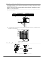
1.1.1 FD-B4L Basic Configuration
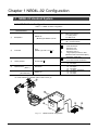
Table 1.1.1 NB04L-02 basic configuration
Reference Number
and Parts Name
①
②
③
④
⑤
(Note
Manipulator
Model Type
Specifications
○
None = Floor-mount
C = Ceiling-mount
W = Wall-mount
△
None : Except for China and Taiwan
CN = China and Taiwan
NB04L-02
(Model Type: NB04L-○△-02)
For NB04L, NV06L
: No External Axis
0
P
: External 1 Axis
FD11
2
: External 2 Axes
Controller
(Model Type: FD11–FL 0 ***)
4
: External 1 Axis x 2
A
: Large-capacity External 1 Axis
(Standard Case External Axis Spec.)
***
: Expansion Case Spec.
: Global icons
1
3
: Icons with Chinese characters
FDTPFSJN-1L**
Teach pendant
**
: 08
8m Spec. (Standard)
15 15m Spec.
**
: 05
5m Spec. (Standard)
Operation Box
10 10m Spec.
FDOP-00**
(Note 1)
15 15m Spec.
**
: 05
5m Spec. (Standard)
Control Cable 1, 3
FDRB-10**
10 10m Spec.
(Wire Harness)
15 15m Spec.
1) In case of not using the operation box, a “connection terminal block” and “selector switch assembly” are required
for mode selection. For details, refer to section 2.2.6 (4).
Fig. 1.1.1
NB04L-02 basic configuration
1
1.1.2 Components of Controller and Welding Power Supply Peripherals (for D
series)
Table 1.1.2
Components of Controller and Welding power supply Peripherals (for D series)
Reference Number and
Parts Name (Note 1)
① Control Cable 5
Model Type
Specifications
□□
FDRB-51□□
△
: 05
10
15
:1
4
6
: 05
10
15
5m Spec. (Standard)
10m Spec.
15m Spec.
DM350, DP350, DR350
DM500, DP500, DP400R
DL350
5m Spec. (Standard)
10m Spec.
15m Spec.
② Cable Hose Group
(Note 2)
A2RB-4△□□
□□
③ Gas Flow Regulator
FCR-226
RF-16D
④ Water Tank
PU-301
L9129C
For CO2 Welding
For MAG Welding (Argon)
Required when using 500A Welding power
supply
For DM
L20365A
For DR, DL and DP
⑤ CAN I/F Board
For DP-400R
L20809A
⑥ Voltage Detecting
Cable (- Side)
(Note 3)
□
L9509□
:B
C
D
5m Spec. (Standard)
10m Spec.
15m Spec.
(Note 1) Please refer to Fig. 1.1.2 for component reference number.
(Note 2) Gas hose, torch side welding cable, work side welding cable and control cable 4 are
contained in the Cable hose group.
(Note 3) Voltage detecting cable (- side) is required when DL series are used.
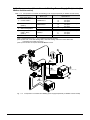
Gas Hose
Control Cable 4
Built-in
Welding Power Supply
Torch Side
Welding Cable
Work Side
Welding Cable
FD11
Fig. 1.1.2
Components of Controller and Welding power supply Peripherals (for D series)
2
1.1.3 Components of Controller and Welding Power Supply Peripherals (for
Welbee Inverter series)
Table 1.1.3
Components of Controller and Welding power supply Peripherals (for Welbee Inverter series)
Reference Number and
Parts Name (Note 1)
Model Type
□□
①
Control Cable 5
FDRB-52□□
②
Cable Hose Group
(Note 2)
A2RB-46□□
③
Gas Flow Regulator
FCR-226
D-BHN-2
④
Voltage Detecting
Cable (- Side)
(Note 3)
Software
⑤
Specifications
: 05
5m Spec. (Standard)
10
10m Spec.
15
15m Spec.
5m Spec. (Standard)
□□ : 05
10
10m Spec.
15
15m Spec.
For CO2 Welding
For MAG Welding (Argon)
:B
5m Spec. (Standard)
□
C
10m Spec.
D
15m Spec.
M350L mode
L9509□
L22153F
(Note 1) Please refer to Fig. 1.1.3 for component reference number.
(Note 2) Gas hose, torch side welding cable, work side welding cable and control cable 4 are
contained in the Cable hose group.
(Note 3) This software is required when WB-M350L is used.
Gas Hose
Control Cable 4
Torch Side
Welding Cable
Built-in
Welding Power Supply
Work Side
Welding Cable
FD11
Fig. 1.1.3
Components of Controller and Welding power supply Peripherals (for Welbee Inverter series)
3
1.1.4 Component of Robot Peripheral
Table 1.1.4
①
Reference Number and
Parts Name (Note 1)
Shock Sensor
Component of Robot Peripheral (Note1)
Model Type
SSB
RT3500H
②
CO2/MAG Welding Torch
RTW5000H
L317X
③
Tip Gauge
L10319H
④
Robot Gauge
L10618B
⑤
Wire Feeding Unit
AF-4011
(For D series /
Welbee Inverter series)
⑥
Fixing Bracket
L10680A
(For AF-4011)
⑦
Coaxial power cable
L-10641
Specifications
Shock Sensor for Manipulator, Type B (Note2)
Air Cooled 350A 45°Curved Torch
(Welding power supply of Rating Output Current:
350A, Standard)
Water Cooled 500A 45°Curved Torch
(Welding power supply of Rating Output Current:
500A, Standard)
Welding power supply: Rating Output Current:
350A
(RT3500* For Torch, Wire Extrusion of 15mm)
Welding power supply: Rating Output Current,
500A
(RTW5000* For Torch, Wire Extrusion of 20mm)
(Option ) For the checking of positional gap of the
robot
Welding Method
: CO2/MAG
Material
: Iron
Feeding Speed
: 1.5 ~ 22m/min.
Encoder
: Yes
Roll
: Four Rolls
(Standard)
Common with Type NB manipulator
(Including Gas EM Valve)
Cable Length: 1.1m
(Standard)
Specification with voltage detection cable of
L-10641 (For DL-350 or WB-M350L)
Floor Rest Type
(Standard)
Mounting on Body Type
Floor Rest Type with 3m Cable Length (Standard)
Mounting on Body Type with 1.8m Cable Length
L-10651
L10085A
L10675A
L10597D
⑨ Conduit
L10597C
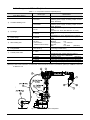
(Note 1) Please refer to Fig. 1.1.4 for component reference number.
(Note 2) In case of a shock sensor not connected, connect the short connector (L21766C00 :optional) to CNMCH on the front
of IPM drive unit.
⑧
Wire Reel Stand
Fig. 1.1.4
Components of Robot Peripheral
4
Chapter 2 NB04L-02 Basic Specifications
2.1 Specifications of NB04L-02 Manipulator
2.1.1 Basic Specifications
Table 2.1.1
NB04L-02 manipulator basic specifications
Item
Wrist load
Max. velocity
Working
range
Name
Structure
Number of axes
Max. payload capacity
Positional repeatability
Drive system
Drive capacity
Position feedback
Axis J1 (Revolving)
Arm
Axis J2 (Lower arm)
Axis J3 (Upper arm)
Axis J4 (Swing)
Wrist
Axis J5 (Bending)
Axis J6 (Twist)
Axis J1 (Revolving)
Arm
Axis J2 (Lower arm)
Axis J3 (Upper arm)
Axis J4 (Swing)
Wrist
Axis J5 (Bending)
Axis J6 (Twist)
Axis J4 (Swing)
Allowable
Axis J5 (Bending)
Moment
Axis J6 (Twist)
Axis J4 (Swing)
Allowable
moment of Axis J5 (Bending)
inertia
Axis J6 (Twist)
Arm operation cross-sectional area
Ambient conditions
Mass (weight)
Upper arm payload capacity
Installation type
Paint color
Specifications
NB04L-02
Vertical articulated type
6
4 kg
+/- 0.08 mm (Note 1)
AC Servo motor
4650W
Absolute encoder
+/- 170° (+/-50°) (Note 2)
-155°~ +100° (Note 5)
-170°~ +190°
+/- 155°
-45°~ +225°(Note 4)
+/- 205° (Note 4)
3.40 rad/s {195°/s} (3.05rad/s{175°/s})(Notes 2)
3.49 rad/s {200°/s}
3.49 rad/s {200°/s}
7.33 rad/s {420°/s}
7.33 rad/s {420°/s}
10.5 rad/s {600°/s}
10.1 N*m
10.1 N*m
2.94 N*m
2
0.38 kg*m
2
0.38 kg *m
2
0.03 kg *m
2
6.37 m x 340°
0 ~ 45℃, 20 ~ 80 %RH (No condensation)
277 kg
20 kg (Note 3)
Floor, ceiling or wall hanging type
White (Munsell 10GY9/1)
Note) 1. The value of the positional repeatability is at the tool center point (TCP) compliant to ISO 9283.
2. The value in the parentheses indicates the wall-hung condition.
3. When loading the Max. payload capacity as the end effector. For details, refer to section 2.1.7.
4. There are occasions where restrictions can be made to the operation range of the J6 axis,
depending on the J5 axis’s posture.
5. There are occasions where restrictions can be made to the operation range of the J2 axis.
IMPORTANT
1. The value of the positional repeatability is at the tool center point (TCP) compliant to ISO 9283.
2. The positional data of absolute encoder is backed up by the battery. The battery backup period with the primary power
OFF is approx. 3 years.
Exceeding this period will require the battery replacement and the absolute offset adjustments.
3. The battery backup period may be shorter depending on the environmental conditions, the use conditions and so on.
4. A holding brake is provided in all axes.
5. The robot itself or peripheral jigs can be cause of interference according to their postures. Please be careful about
any interference when you teach the robot.
6. The above specifications are subject to change without notice.
5
130
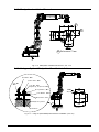
2.1.2 Outside Dimensions and Working Range
1505
P-Point
Fig. 2.1.1
Outside Dimensions and Working Range of NB04L-02 (unit : mm)
6
2.1.3 Allowable Load on Wrist Axis
The payload of manipulator must not exceed max. payload capacity 4kg, including a welding torch, a chucking
tool in handling and a workpiece.
Mounting a standard welding torch does not cause any problems to the manipulator, but both the moment and the
moment of inertia must be within the allowance stated in the table below when the manipulator is used for
handling or any other similar purposes.
Also, when a load is imposed not in the form of mass but force, a wrist axis must not be used with these maximum
allowable values exceeded.
Table 2.1.2
Axis
Name
Axis J4
Axis J5
Axis J6
Allowable Load on Wrist Axis
NB04L-02
Allowable Moment of Inertia
2
0.38 kg *m
0.38 kg *m2
0.03 kg *m2
220
Allowable Moment
10.1 N*m
10.1 N*m
2.94 N*m
(mm)
W=4kg
W=3kg
258
300
345
400
(mm)
Distance from Axis J5
Rotation Center
Distance from Axis J6
Rotation Center
Note: Though the center of gravity shown above fully satisfies the allowable load moment, the allowable moment
of inertia is not always satisfied.
Fig. 2.1.2 Allowable Load on Wrist Axis
Fig. 2.1.3
Wrist load conditions
4.5
2.1.4 Flange Dimensions of Wrist Axis
φ57 H7
φ
45°
4XM5 10 Deep
(equally spaced)
2xφ6 H7 6 Deep
(equally spaced)
P.C.D.67
View A
A
Fig. 2.1.4
Flange Dimensions of Wrist Axis (unit : mm)
7
2.1.5 Manipulator Installation Dimensions
RP
RP
RP :Reference Plane
A
Fig. 2.1.5
Manipulator Installation Dimensions(unit : mm)
2.1.6 Using an Optional Manipulator Stand for Installation
Jack Bolt (M12)
Anchor Bolt (M16)
Lock Nut (M16)
(Tightening Torque:107.8N・m)
Spring Washer (M16)
Flat Washer (M16)
4xM12
4xφ18
420
320
420
Lock Nut
(M12)
Manipulator Stand
Supporting Plate
500
View A
Foundation
Fig. 2.1.6
Using an Optional Manipulator Stand for Installation (unit: mm)
8
2.1.7 Mounting Equipment on the Upper Arm
On the top, back and side of the upper arm, there are specific areas prepared for devices such as a
wire feeding unit and gas solenoid valve to be mounted. To mount a device, use M8 holes.
(a) Restriction of the maximum mountable mass on the upper arm.
The max. mountable mass on the upper arm depends on the max. wrist axis payload capacity.
Calculate it by the figure below, not exceeding the value “C”.
A+B1+B2≦C
A : Max. wrist payload capacity (kg)
B1: Mountable mass on the Top of upper arm (kg)
B2: Mountable mass on the Back of upper arm (kg)
C : Max. mountable mass (kg)
NB04L-02
Max. 4kg
Max. 2kg
Max. 20kg
24kg
A
B1
B2
C
Suppose that the wrist has a mass of 3 kg including a holder. In this case, the upper arm can be
mounted with an equipment of 21 kg (total B1 + B2) or less.
(b) The center-of-gravity position for mounting an equipment on the upper arm must be within the 100-mm
pitch position of 4XM8 tapping holes.
(When mounting the equipment on the back, be careful not to intervene the area of NOT-endurable shown
by hatching in the figure below.)
95
100※
40
50
40
4xM8
16 Deep
2xM8
16 Deep
117
Area of "B 2 " NOT
endurable
50 70
126
141
110 20 105
2xM8
16 Deep
133
107
126
300
N.P.
200
121
Fig. 2.1.7
25
9
4xM8
16 Deep
2xM8
12 deep 9
25
Area of "B 2 " NOT
endurable
Equipment Mounting Position on the Upper Arm of NB04L-02 Manipulator (unit: mm)
9
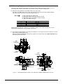
2.1.8 Instrument Connecting Cables and Gas (Air) Piping
Inside the manipulator, the instrument connecting cables and a gas (air) hose are built in for a wire feeding unit
mounted on top of the upper arm and for driving or signaling instruments such as a gas solenoid valve.
Cable Outlet
Cable
Gas(Air)Hose
Instrument Connection Cables
0.3mm 2 ×6pcs+
0.5mm 2 ×2pcs+1.25 mm 2 ×4pcs
+Shield
Pins
2
1
5
6
4
3
7
8
9
10 11 12 13
14 15 16
1
2
3
4
5
6
7
8
9
10
11
12
13
14
15
16
NC
Cable [0.3mm ]
Cable [0.3mm ]
Cable [0.3mm ] ※
Cable[0.3mm ]
NC
Cable [0.3mm ]
Cable [0.3mm ]
NC
Cable [0.5mm ]
Cable [0.5mm ]
Cable [1.25mm ]
Cable [1.25mm ]
Cable [1.25mm ]
Cable [1.25mm ]
Shield
2
2
2
2
2
2
2
2
2
2
2
2
<Allocation of CN4 Connector Pins>
M AX PR ESSUR E
1.0 M Pa (145psi)
Welding cable terminal(M10)
Fig. 2.1.8
Instrument Connecting Cables and Gas (Air) Piping for NB04L-02 Manipulator
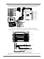
For welding application, Fig 2.1.9 below shows the wiring diagram of the built-in cables in the manipulator.
Electrical Connection of Manipulator
Base Side
Upper Arm Side
CN29
CN4
SRCN2A25-16P
SRCN6A25-16S
White
Red
Yellow,Blue,Green
Orange
Wire Feed Device(Encorder)
CN41
Gray
Black
SOL Gas Solenoid Valve
CN26
Yellow
Blue
White
Others
CN27
Red
Black
Wire Feed Device(Motor)
CN28
Green
Others
MOLEX 58691-0020
CN2
Red
White
Yellow
Blue
Warning Lamp
Shock Sensor LS
Welding Cable Connection Terminal
Terminal size M10 Electric Wire size 80mm 2
Fig 2.1.9 NB04L-02 Cable Wiring (for welding application)
When using these built-in cables for applications other than welding, prepare the counter-connectors shown
from Fig. 2.1.8.
10
2.2 FD11 Robot controller
2.2.1 Basic specifications
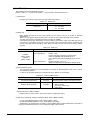
Table 2.2.1
Basic specifications of robot controller
Item
Specifications
Model
FD11-FL0
Number of control axes
(Note 1)
6 axes (Up to 8 axes can be controlled by built-in extension.)
Maximum control axes are up to 32 axes. (However, note that the exterior of
controllers with a total of 9 or more axes is a different specification.) (Note 2)
(For NB04L / NV06L)
Driving system
AC servo motor
Positional feedback
Absolute encoder
Teaching playback
Teaching system
Robot language based on JIS SLIM
IEC61131-3 (Software PLC) (Optional)
Number of task programs
9,999
Memory capacity
160,000 steps (by PTP instruction in a single mechanism)
Teach pendant
5.7 inch color LCD (640 x 480 pixels, with LED backlight、65536-color display)
Touch panel, Jog dial, one-handed 3-postional enable switch and emergency stop
button are included as standard.
IP code is IP65.
Standard cable length is 8 m.
Operation box
Emergency stop button, Motor on button, Start button, Stop button and Mode select
switch are included as standard.
Standard cable length is 5 m.
Manipulator connecting cable
External memory I/F
Standard cable length is 5 m
Input 8 points, Output 8 points
Number of
Extension of input and output is allowed respectively up to 72
Signals
points
DC24V 8mA
Input
Connect the relay contact (Dry contact) which minimum
specifications
applicable load is DC24V,5mA, or open-collector device whose
leakage current is up to 1mA.
Output
DC24V / AC100V Up to 1A
specifications
(Minimum applicable load (reference): DC24V, 5mA)
USB memory (Optional)
Structure
Closed structure
Cooling system
Indirect cooling system
Ambient conditions
Temperature: 0 - 45 ℃, Humidity: 20 - 80 %RH (Non-condensing)
Primary power
3-phase AC 200 V / 220 V (+10%、-15%),
I/O Control over External
Equipment
(Note 3)
Power consumption
50 / 60 Hz
Manipulator
Power capacity (Note 4)
NB04L-02
2.4 kVA
Grounding
Ground the robot controller separately whose resistance is less than 100 ohms.
External dimensions
W 580 × D 542 × H 650 (mm)
Mass
Approx. 62 kg
Paint color
10GY9/1, Munsell scale
(Note 1) When the capacity of the motor an additional axis is 2kW or more, the number of control axes is limited.
(Note 2) In case that number of control axes exceeds 32, contact us.
(Note 3) The number of I/O can be enlarged to up to 2048 points by installing optional field bus such as CC-link,
DeviceNet or Ethernet/IP, etc.
(Note 4) Varies according to the application and operation pattern.
11
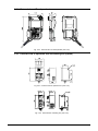
2.2.2 Outside dimensions
Eye bolts
Primary power inlet
Teach pendant hanger
Breaker
handle
Door key
1. 接 地 等の 接 続を 行 う 際 は 取扱 説 明 書 を よく お 読 み下 さ い 。
2. 接 地 ケー ブ ルお よ び 一 次 側電 源 ケ ー ブ ルを 制 御 装 置 内 部の
所 定 の端 子 に 接 続 して 下 さい 。
( 接 地ケ ー ブ ルを 先 に 接 続 して 下 さい 。 )
3. 接 地 ケー ブ ル が 正 しく 接 続 さ れ、 接 地 抵抗 が 1 00Ω 以 下 と
な っ て い る こと を 確認 し て 下 さ い。
4. 主 電 源投 入 前に 接 地 ケ ー ブル の 接 続 、 一次 側 電 源の 電 圧
お よ び 周 波 数を 再 度 確 認し て 下 さい 。
● Read manual for connection procedures.
● Connect grounding conductor and input
conductors to proper terminals inside
unit-grounding conductor first.
● Be sure grounding conductor goes to a proper
earth ground and has less than 100 ohms of
resistance.
● Doublecheck grounding conductor,input
voltage,and frequency before applying power.
通 気 口 をふ さ ぐ と 機 器に 損 傷 を 及 ぼす こ と が あ りま す 。
制 御 装 置の 通 気 口 は 、通 気 の た め 壁か ら 0 .1m 以 上離 し て
設 置 し てく だ さ い。
また 熱 源 の 近 くは 避 けて く だ さ い 。
To avoid damage to the robot controller.
Keep the air inlet and outlet clear.
(At least 0.1m from wall)
1.通電中は本装置内部の部品に触れないでください。
2.設置及び点検時には一次側の電源を遮断してくだ
さい。
3.充電部がありますので、電源を遮断した後3分間
は本装置内部の部品に触れないでください。
1.Do not touch live electrical parts.
2.Disconnect all power before installing or
servicing.
3.Multiple sources of voltage may exist inside
this enclosure.
1.主電源ON時には ロボットの動作範囲内に入らな
いでください。
2.必ずロボット動作範囲外に取り付けてください。
3.取扱説明書をよくお読みください。
4.保守点検時は、ブレーカに鍵をかけてください。
1.Keep out of robot area when main power is on.
2.Do not locate this device in robot work area.
3.Read instruction manual.
4.Lockout and tagout equipment, before
servicing.
制御装置内にヒュームやほこりが侵入すると、
故障や誤動作の原因となります。
・ロボット制御装置の扉は、ドアキー(2カ所)を
かけて確実に閉めてください。
・未使用のケーブル引き込み口には、
カバを取り付けてください。
Door key
Fume or dust will cause failures and
malfunctions of the Controller.
- Close the door of the Controller and lock
the 2 door keys certainly.
- Attach covers to the unused cable ports on
the Controller.
Column composing holes
Fig. 2.2.1
Outside dimensions of robot controller (Unit : mm)
2.2.3 Install method of robot controller
Fig. 2.2.2
Concerning the robot controller installation method (Unit : mm)
12
2.2.4 External view of Teach pendant
Fig. 2.2.3
External view of Teach pendant (Unit: mm)
2.2.5 External view of operation box and starting box (option)
Fig. 2.2.4
Fig. 2.2.5
External view of operation box (Unit: mm)
External view of starting box (Unit: mm)
13
2.2.6 FD11 Option
The following products are prepared as option.
Refer to section 1.1.1 for the control cables 1, 3, Teach pendant and the operation box.
(1) Starting box
Emergency stop button, Start button and Stop button are included.
Table 2.2.2
Starting box
Model
Specifications
** : 05
5m Spec.
10 10m Spec
15 15m Spec.
FDST-00**
(2) Relay unit
Eight general physical input and output signals can be used on the arc I/F board as standard
specifications.
When 9 or more general physical input points or output one are required, the relay unit is required.
The relay unit is used in combination with the I/O board L21700M00.
A standard physical input specification is common GND (The transistor output of the NPN type can be
connected). It is possible to change to a common power supply (The transistor output of the PNP type
can be connected) with the accessory cable. When two relay units are used, each accessory cable is
required.
Table 2.2.3
Model
Number of signals
Input specifications
L22254A
(Relay unit #1)
L22255A
(Relay unit #2)
Output specifications
Relay unit
Specifications
: IN 32 pts. / Out 32 pts.
: DC24V 8mA
Connect the relay contact (Dry contact) which
minimum applicable load is DC24V,5mA, or
open-collector device whose leakage current is up to
1mA.
: DC24V / AC100V Up to 1A
(Minimum applicable load (reference): DC24V, 5mA)
(3) External starting option
The use of the operation box is recommended for the switch of Teach/Playback mode, even in case of
external starting method.
In case of not using the operation box, the parts shown in Table 2.2.4 are required.
Table 2.2.4
External starting option
Part name
Model
Specifications
Connection terminal block
L21767A
Sequence board CNOP to terminal block TB1
L21768A
Component
- Selector switch
- Connection cable (15 m)
- Cable flange
Selector switch assembly
(4) External memory USB L21700U00
External memory USB is used to back up user data or upgrade the version.
(5) Step-down transformer L22221A (3kVA) (for NB04 / NV06 / NB04L / NV06L)
For out of the standard primary power voltage (AC200 - 220V).
AC 380/400/420/440/460/480V +/-10%, 3φ 50/60Hz, D grounding
Additional box for transformer is necessary on the standard cabinet. External dimension of controller is
changed to W580*D542*H950 mm (not including the height of stand 60mm).
14
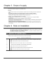
Chapter 3 Scope of supply
Note that users shall be charged for any installation work.
[Example]
- Connection with the robot and robot peripherals, operation check, and welding check with a standard test
piece
- Discharging and carrying-in work by using the facilities of either your company or NACHI
- Wiring and piping of the NACHI -manufactured jigs, I/F check, and interlocking trial operation
- Teaching work, welding conditions adjustment, operator education, etc.
In addition, carry out all following works by your company.
- Foundation work of installation location for robot and jigs (including both your company and NACHI
manufactured)
- Anchor fixation work, laying iron plate, embedding, concrete construction
- Powering of the robot and jigs (including both your company and NACHI manufactured), primary wiring and
piping of the air, and their protection work
- Wiring and piping work for connecting the jig and jig controller prepared by your company with the robot,
welding power supply and other peripherals equipment
- Grounding work for the robot, welding power supply, jigs, and jig controller (prepared by both NACHI and
your company)
Chapter 4 Note on Installation
The locations in which the manipulator is installed and the method used to install it are critical for
ensuring that the functions of the robot will be maintained.
The ambient atmosphere in the installation location not only affects the lifespan estimation of the
mechanisms but it also has a bearing on safety.
4.1 Selection of Installation place
Install the robot in the place where all the following conditions are satisfied.
Table 4.1.1
Check item of installation place
(1)
□
Avoid direct sunlight, and the ambient temperature must be in the 0 to 45 degrees Celsius range.
(2)
□
The ambient relative humidity must be less than 80%RH.
(3)
□
The amounts of dust, dirt, oily vapors, water, etc. must be minimal.
(4)
□
There must be no flammable or corrosive liquids or gases present.
(5)
□
The vibration level must be less than 0.5G (4.9m/s2 ).
(6)
□
No major sources of electrical noise must be in the vicinity of the robot.
(7)
□
There must be no direct wind of 2 m/sec or more to arc part.
15
4.2 Installation of guarding fence and the layout of
peripheral equipments
Install a guarding fence as the following, so that no one enters the manipulator’s work area during automatic
operation.
Install robot controller, operation box, teach pendant and starting box (option) outside the guarding fence.
DANGER
Install robot controller, welding power supply and the peripheral equipments as operation
box outside the guarding fence.
安全防護柵
Guarding
fence
11m以上
m or more
1 m or
more
1m以上
ロボット動作範囲
Robot
working range
1 m or
more
1m以上
扉
Door
ロボット制御装置
Robot controller
Fig. 4.2.1
F9
F8
F2
F3
F4
F5
F6
F1
11m以上
m or more
F7
操作ボックス
Operation box
ティーチペンダント
Teach pendant
溶接機
Welding power supply
制御ケーブル5及びセンサケーブル
Control cable 5
Installation of guarding fence
When the installation place of robot controller is selected, note the following points.
(1) When installing the controller, leave a clearance of at least 100 mm between the controller and the wall
behind it in order to ensure proper ventilation inside the robot controller. At the rear side, secure a space of
400 mm at least for external connection cable.
(2) To install a robot controller and welding power supply, etc. on a place two or more meters in height such as
a frame base, a foothold as described in Fig. 4.2.2 is required so that adjustment and maintenance, etc. can
be performed.
Fig. 4.2.2
Installation of robot controller
16
Chapter 5 Notes on Safety
For handling a robot, comply with the rules and regulations for industrial robots.
Chapter 6 Warranty
Elapse of 1 year after delivery. (8 hours / day running)
17
本頁は履歴管理用頁ですので印刷しないでください。また、本頁を削除しないでください。
(“ツール”→“オプション”から、編集記号の表示で“全て”をチェックすれば表示されます。)
NOTE
18
http://www.nachi-fujikoshi.co.jp/
JAPAN MAIN OFFICE
Phone:
+81-3-5568-5245
http://www.nachirobotics.com/
NACHI NORTH AMERICA
North America Headquarters
Greenville Service Office
San Antonio Service Office
Shiodome Sumitomo Bldg. 17F,
1-9-2 Higashi-Shinbashi
Minato-ku, TOKYO, 105-0021 JAPAN
Fax:
+81-3-5568-5236
Phone: 248-305-6545
Fax: 248-305-6542
22285 Roethel Drive, Novi, Michigan 48375 U.S.A.
Use 248-305-6545
Use 248-305-6542
South Carolina, U.S.A.
Use 248-305-6545
Use 248-305-6542
Texas, U.S.A.
Kentucky Branch Office
Phone: 502-695-4816
Fax: 502-695-4818
116 Collision Center Drive, Suite A, Frankfort, KY 40601 U.S.A
Training Office
Phone: 248-334-8250
Fax: 248-334-8270
22213 Roethel Drive, Novi, Michigan 48375 U.S.A.
Toronto Branch Office
Phone: 905-760-9542
Fax: 905-760-9477
89 Courtland Avenue, Unit 2, Vaughan,
Ontario L4K3T4 CANADA
Mexico Branch Office
Saltillo Service Office
Phone :
+52-555312-6556
Phone :
+52-844416-8053
Fax:
+52-55-5312-7248
Fax:
+52-844416-8053
Urbina # 54, Parque Industrial Naucalpan,
Naucalpan de Juarez, 53370, Estado de México, MEXICO
Canada 544 Privada Luxemburgo
C. P. 25230, Saltillo, Coahuila, MEXICO
NACHI ROBOTIC EUROPE
Germany
Nachi Europe GmbH
http://www.nachi.de/
Phone:
Fax:
+49-(0)2151-65046-0
+49-(0)2151-65046-90
Bischofstrasse 99, 47809, Krefeld,GERMANY
United Kingdom
Nachi U.K. LTD.
http://www.nachi.co.uk/
Phone:
+44-(0)121-250-1895
Fax:
+44-(0)121-250-1899
Unit 7, Junction Six Industrial Estate, Electric Avenue,
Birmingham B6 7JJ, U.K.
Czech Republic
Nachi Europe
Phone:
Fax:
+ 420-255-734-000
+420-255-734-001
NACHI SHANGHAI CO., LTD.
Representative
Office
Phone:
+86-(0)21-6915-2200
http://www.nachi.com.cn/
Fax:
+86-(0)21-6915-2200
NACHI KOREA
Representative
Office
Prague 9, VGP Park, Czech republic
11F Royal Wealth Centre, No.7
Lane 98 Danba Road Putuo District, Shanghai 200062, China
http://www.nachi-korea.co.kr/
Phone:
Fax:
2F Dongsan Bldg.
+82-(0)2-469-2254
+82-(0)2-469-2264
276-4, Sungsu 2GA-3DONG, Sungdong-ku,
Seoul 133-123, KOREA
Copyright NACHI-FUJIKOSHI CORP.
Robot Division
1-1-1, FUJIKOSHIHONMACHI, TOYAMA CITY, JAPAN 930-8511
Phone +81-76-423-5137
Fax
+81-76-493-5252
NACHI-FUJIKOSHI CORP. holds all rights of this document. No part of this manual may be photocopied or
reproduced in any from without prior written consent from NACHI-FUJIKOSHI CORP. Contents of this document may
be modified without notice. Any missing page or erratic pagination in this document will be replaced.
In case that an end user uses this product for military purpose or production of weapon, this product may be liable for
the subject of export restriction stipulated in the Foreign Exchange and Foreign Trade Control Law. Please go
through careful investigation and necessary formalities for export.
Original manual is written in Japanese.
©