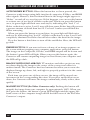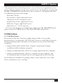
1
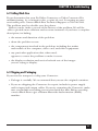
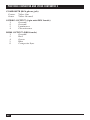
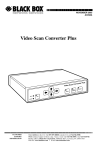
FEBRUARY 1995
AC095A
AC096A
ProVideo Converter
Video Scan Converter II
verter
eo Con
ProVid
IFY
MAGN
INPUT
UNDER
SCAN
HOME
ANTIR
FLICKE
FREEZE
verter II
an Con
TEST
c
Video S
POWER
UNDER
SCAN
INPUT
ANTIR
FLICKE
FREEZE
TEST
POWER
CUSTOMER
SUPPORT
INFORMATION
Order toll-free in the U.S. 24 hours, 7 A.M. Monday to midnight Friday: 877-877-BBOX
FREE technical support, 24 hours a day, 7 days a week: Call 724-746-5500 or fax 724-746-0746
Mail order: Black Box Corporation, 1000 Park Drive, Lawrence, PA 15055-1018
Web site: www.blackbox.com • E-mail: [email protected]
FCC AND IC STATEMENTS, TRADEMARKS
FEDERAL COMMUNICATIONS COMMISSION
AND
INDUSTRY CANADA
RADIO FREQUENCY INTERFERENCE STATEMENTS
This equipment generates, uses, and can radiate radio frequency energy
and if not installed and used properly, that is, in strict accordance with the
manufacturer’s instructions, may cause interference to radio communication.
It has been tested and found to comply with the limits for a Class A
computing device in accordance with the specifications in Subpart J of
Part 15 of FCC rules, which are designed to provide reasonable protection
against such interference when the equipment is operated in a commercial
environment. Operation of this equipment in a residential area is likely to
cause interference, in which case the user at his own expense will be required
to take whatever measures may be necessary to correct the interference.
Changes or modifications not expressly approved by the party responsible
for compliance could void the user’s authority to operate the equipment.
This digital apparatus does not exceed the Class A limits for radio noise emission from
digital apparatus set out in the Radio Interference Regulation of Industry Canada.
Le présent appareil numérique n’émet pas de bruits radioélectriques dépassant les limites
applicables aux appareils numériques de classe A prescrites dans le Règlement sur le
brouillage radioélectrique publié par Industrie Canada.
TRADEMARKS USED IN THIS MANUAL
Apple, Mac, and Macintosh are registered trademarks of Apple
Computer, Inc.
IBM is a registered trademark of IBM Corporation.
RCA is a registered trademark of General Electric Co.
UL is a registered trademark of Underwriters Laboratories
Incorporated.
Any other trademarks mentioned in this manual are acknowledged to be the property
of the trademark owner.
PROVIDEO CONVERTER AND VIDEO CONVERTER II
NORMAS OFICIALES MEXICANAS (NOM) ELECTRICAL SAFETY STATEMENT
INSTRUCCIONES DE SEGURIDAD
1. Todas las instrucciones de seguridad y operación deberán ser leídas antes
de que el aparato eléctrico sea operado.
2. Las instrucciones de seguridad y operación deberán ser guardadas para
referencia futura.
3. Todas las advertencias en el aparato eléctrico y en sus instrucciones de
operación deben ser respetadas.
4. Todas las instrucciones de operación y uso deben ser seguidas.
5. El aparato eléctrico no deberá ser usado cerca del agua—por ejemplo,
cerca de la tina de baño, lavabo, sótano mojado o cerca de una alberca,
etc..
6. El aparato eléctrico debe ser usado únicamente con carritos o pedestales
que sean recomendados por el fabricante.
7. El parato eléctrico debe ser montado a la pared o al techo sólo como sea
recomendado por el fabricante.
8. Servicio—El usuario no debe intentar dar servicio al equipo eléctrico más
allá a lo descrito en las instrucciones de operación. Todo otro servicio
deberá ser referido a personal de servicio calificado.
9. El aparato eléctrico debe ser situado de tal manera que su posición no
interfiera su uso. La colocación del aparato eléctrico sobre una cama,
sofá, alfombra o superficie similar puede bloquea la ventilación, no se
debe colocar en libreros o gabinetes que impidan el flujo de aire por los
orificios de ventilación.
10. El equipo eléctrico deber ser situado fuera del alcance de fuentes de
calor como radiadores, registros de calor, estufas u otros aparatos
(incluyendo amplificadores) que producen calor.
11. El aparato eléctrico deberá ser connectado a una fuente de poder sólo
del tipo descrito en el instructivo de operación, o como se indique en
el aparato.
NOM STATEMENT
12. Precaución debe ser tomada de tal manera que la tierra fisica y la
polarización del equipo no sea eliminada.
13. Los cables de la fuente de poder deben ser guiados de tal manera que
no sean pisados ni pellizcados por objetos colocados sobre o contra ellos,
poniendo particular atención a los contactos y receptáculos donde salen
del aparato.
14. El equio eléctrico debe ser limpiado únicamente de acuerdo a las
recomendaciones del fabricante.
15. En caso de existir, una antena externa deberá ser localizada lejos de las
lineas de energia.
16. El cable de corriente deberá ser desconectado del cuando el equipo no
sea usado por un largo periodo de tiempo.
17. Cuidado debe ser tomado de tal manera que objectos liquidos
no sean derramados sobre la cubierta u orificios de ventilación.
18. Servicio por personal calificado deberá ser provisto cuando:
A: El cable de poder o el contacto ha sido dañado; u
B: Objectos han caído o líquido ha sido derramado dentro
del aparato; o
C: El aparato ha sido expuesto a la lluvia; o
D: El aparato parece no operar normalmente o muestra un cambio
en su desempeño; o
E: El aparato ha sido tirado o su cubierta ha sido dañada.
PROVIDEO CONVERTER AND VIDEO CONVERTER II
Contents
Chapter
Page
1.
Specifications ............................................................................................. 1
2.
Introduction ............................................................................................... 4
3.
Installation ..................................................................................................
3.1 Initial Steps ..........................................................................................
3.2 Hooking Up Video Output ................................................................
3.3 Selecting Your Video Standard ..........................................................
3.4 Booting Your Converter System .........................................................
4.
Operation ................................................................................................... 8
4.1 Indicators ............................................................................................. 9
4.2 Using the Front-Panel Controls ......................................................... 9
4.3 Other Features .................................................................................. 11
5.
What to Expect from Converted Computer Images .............................. 13
6.
Troubleshooting ......................................................................................
6.1 Common Concerns ...........................................................................
6.2 Calling Your Supplier .......................................................................
6.3 Shipping and Packaging ...................................................................
5
5
5
7
7
15
15
17
17
Appendix A: S-Video, the Improved-Quality Video Standard ...................... 18
Appendix B: Connector Pinouts .................................................................... 19
CHAPTER 1: Specifications
1. Specifications
Approvals —
FCC Part 15 Class A, IC Class/classe A
System Software
Required —
None
Standards —
Input, Computer Output: VGA, SVGA, or Mac video
at the refresh rates and resolutions listed below;
Television Output: NTSC or PAL composite,
S-Video (including Hi-8 and Beta-ED), and/or RGBS
Compatibility —
All operating systems and environments
Color —
Up to 24-bit (“true”) color (16.8 million colors)
Refresh Rates and
Resolutions —
ProVideo Converter (AC095A):
VGA, SVGA:
320 x 200, 640 x 200, and 640 x 350 at 70 Hz;
640 x 480 at 60, 72, 73, or 75 Hz;
720 x 350 and 720 x 400 at 70 Hz;
800 x 600 at 56, 60, 70, 72, 73, and 75 Hz;
1024 x 768 at 60, 70, 72, 73, and 75 Hz;
Mac:
640 x 480 at 66 Hz;
832 x 624 at 75 Hz;
1024 x 768 at 60 Hz;
Video Converter II (AC096A):
VGA, SVGA:
320 x 200, 640 x 200, and 640 x 350 at 70 Hz;
640 x 480 at 60, 72, 73, or 75 Hz;
720 x 350 and 720 x 400 at 70 Hz;
800 x 600 at 56, 60, 70, 72, 73, and 75 Hz;
Mac:
512 x 384 at 60 Hz;
640 x 480 at 66 Hz;
832 x 624 at 75 Hz
1
PROVIDEO CONVERTER AND VIDEO CONVERTER II
Computer- and TVVideo Processing —
Input Sampling: 24-bit (8 bits per RGB), 708 samples
per active portion of computer-video line;
Graphics-Mode Detection: Automatic;
Video Processing: 24-bit separate RGB;
Video-Memory Size: 708 x 740 x 24 bits (1 video
frame);
Video-Encoding Process: 24-bit RGB encoding with
10-bit output D/A;
RGB Output Processing: 24-bit RGB with 3 x 8-bit
output D/A;
Differential Gain: Less than 1%;
Differential Phase: Less than 1˚;
Frequency response for composite, S-Video: 6.5 MHz
(–3 dB)
User Controls —
(9 [AC096A] or 10 [AC095A]) External:
(1) Rear-mounted slide switch for NTSC/PAL
selection;
(8 [AC096A] or 9 [AC095A]) Front-mounted
pushbuttons:
Both models: (1) Underscan, (1) Flicker
Reduction, (1) Freeze Image, (1) Test,
(4) Image Positioning;
AC095A only: (1) Magnify
Indicators —
(6 [AC096A] or 7 [AC095A]) Front-mounted LEDs:
(2) on panel: Power, Input;
(4 [AC096A] or 5 [AC095A]) on buttons:
Both models: Underscan, Flicker Reduction,
Freeze Image, Test;
AC095A only: Magnify
Connectors —
(6) Rear-mounted:
(1) DB15 female for VGA input or Mac output;
(1) DB15HD female for Mac input or VGA
output;
(1) RCA phono jack for composite output;
(1) 4-pin mini-DIN female for S-Video output;
(1) DB9 for RGBS output;
(1) Inverted phono jack for power
2
CHAPTER 1: Specifications
Power —
From UL®, CSA, and TUV certified desktop power
supply:
Input range: 95- to 250-VAC, 47 to 63 Hz
(autosensing) at 0.9 amps;
Output: 5 VDC at 5 amps
Size —
1.5"H x 7.25"W x 6.25"D (3.9 x 18.5 x 15.9 cm)
Weight —
3 lb. (1.4 kg)
3
PROVIDEO CONVERTER AND VIDEO CONVERTER II
2. Introduction
Thank you for purchasing the ProVideo Converter or Video Converter II. We
are sure you will find it to be a reliable and useful product. You now have the
ability to convert your computer monitor’s signal into a form suitable for
recording on a VCR, displaying on a conventional TV or video monitor, or
integrating into a multimedia production system. And you can do this without
installing any boards or software in your computer!
Chapters 3 and 4 of this manual show you how to install and operate your
Converter. Chapter 5 gives you some guidelines on what you should (and
shouldn’t) expect from your converted computer images and explains how
to get the best quality of image display. Chapter 6 gives you tips for handling
problems that might occur with your Coverter system. Appendix A explains
what S-Video is and why it should be used as output from your Converter
whenever possible. Lastly, Appendix B shows the pinouts of all of your
Converter’s connectors.
4
CHAPTER 3: Installation
3. Installation
Follow the procedure outlined in this chapter to install your ProVideo
Converter or Video Converter II.
3.1 Initial Steps
1. Disconnect your monitor from the monitor port on your computer.
2. Connect one end of the special 6-foot (1.8-m) input cable provided with
the Converter to the monitor port on your computer. (See Section 4.3.3
for more info on this cable.) Plug the other end into the appropriate
connector on the rear panel of the Converter: either the one labeled
VGA IN if you are taking VGA video from an IBM® PC or compatible
or the one labeled MAC IN if you are taking Macintosh® video from
an Apple® Macintosh. See Figures 3-1 and 3-2 on the next page.
3. If you want your monitor to continue to display, connect it to the
appropriate MONITOR output connector, either VGA OUT or
MAC OUT. See the next section for a description of this ouput.
4. Plug the output cord of the power supply provided with the Converter
into the connector labeled POWER. Plug the power supply’s input cord
into the wall outlet to provide power to the Converter. (If you ever need
an AC-line cord specific to another country, call Black Box.)
5. Connect your video equipment to one or more of the Converter’s video
outputs (refer to the next section).
5
PROVIDEO CONVERTER AND VIDEO CONVERTER II
RGB
NTSC
S-VIDEO
COMPOSITE
IN
VGA
OUT
OUT
MAC
IN
POWER
PAL
NTSC/PAL
switch for
selecting the
appropriate
video standard
Highest-quality
RGBS output
S-Video
output with
separate,
clearer Y/C
video signals
Either VGA video input
from computer or
Macintosh video output
for local Mac monitor
Composite video
ouput for standard
video equipment
Power supply
(line cord from
transformer
plugs in here)
Either Macintosh video
input from computer or
VGA video output for
local VGA monitor
NOTE: All outputs are available at the same time. You don’t have to terminate
unused outputs.
Figure 3-1. Rear panel shared by the ProVideo Converter
and Video Converter II.
3.2 Hooking Up Video Output
Now connect one or more of the Converter’s output ports to your video
equipment:
COMPOSITE (RCA® jack): You can feed this single composite-video output
signal into the “video” input jacks on ordinary TVs, monitors, VCRs, or
professional video equipment. It cannot be connected to the “antenna” input.
S-VIDEO (4-pin mini-DIN female): Called S-Video, S-VHS, or Y/C, this
output is an advanced form of video which carries the brightness and color
parts of images on two separate signals. It is compatible with the Hi-8 and
Beta-ED standards. Feed it into compatible equipment by using the included
S-Video cable and you’ll get a better-quality picture than the COMPOSITE
output can provide.
RED, GREEN, BLUE, SYNC (DB9 female): This premium-quality output,
which can be used by some video projectors and monitors, consists of separate
red, green, blue, and sync signals. If you’d like to use this output with compatible equipment, call your supplier for a special quote on RGBS cable with
a male DB9 connector on one end and male BNC connectors, European
SCART connectors, or connectors for Sharp LCD projectors on the other end.
All outputs are available at the same time. You don’t have to terminate
unused outputs.
6
CHAPTER 3: Installation
3.3 Selecting Your Video Standard
Use the NTSC/PAL slide switch on the back of your Converter to choose
which standard you’ll use for the VIDEO, S-VIDEO, and RGB outputs. NTSC
is the video standard for the USA, Canada, Mexico, Japan, and parts of South
America. PAL is used throughout most of Europe, the Middle East, Southern
Asia, and the Pacific Rim.
3.4 Booting Your Converter System
If you haven’t already done so, plug in and turn ON your computer. The
green indicator labeled LOCK on the Converter’s front panel should light,
showing that the Converter is receiving a proper signal from the computer.
(Refer to Chapter 5 for more information about this indicator.) Make sure
the FREEZE IMAGE switch on the front panel is in the NORMAL position,
so that your computer-image sequences will flow smoothly.
Your ProVideo Converter or Video Converter II is now ready for normal
operation.
7
PROVIDEO CONVERTER AND VIDEO CONVERTER II
4. Operation
The ProVideo Converter and Video Converter II are designed for ease of use,
reliability, intelligence, and high performance. We hope you’ll find that using
your Converter is pretty simple, especially since there are few controls to
adjust and no hidden DIP switches to set. However, we suggest you read this
chapter carefully so you can fully understand how your Video Converter
operates and can take advantage of all its features.
Figure 4-1, below, shows the front panels of the ProVideo Converter
and Video Converter II with their buttons and indicators.
ProVideo Converter
INPUT
TEST
MAGNIFY
POWER
Outputs test
patterns when
TEST is pressed / lit
Receiving power
when POWER is lit;
input signal from
computer is OK
when INPUT is lit
UNDER
SCAN
HOME
Outputs enlarged portion of
image when MAGNIFY is
pressed / lit; outputs center/
corner portions when HOME
is pressed
ANTIFLICKER
FREEZE
Anti-flicker filter
is active when
ANTI-FLICKER
is pressed / lit
Moves image when
Image is “shrunk” in both
IMAGE POSITIONING the horizontal and vertical
ARROWS
directions when
are pressed
UNDERSCAN is pressed / lit
Image is “frozen”
on the screen
when FREEZE is
pressed / lit
Video Scan Converter II
INPUT
TEST
UNDER
SCAN
ANTIFLICKER
FREEZE
POWER
Figure 4-1. The front panels of the ProVideo Converter
and Video Converter II.
8
CHAPTER 4: Operation
4.1 Indicators
Most of the Converter’s indicators are mounted in, and function in concert
with, its front-panel pushbuttons; these indicators are described in the next
section. There are also two independent LEDs mounted in the front panel:
POWER: This indicator lights when your Converter is ON (receiving DC
power through its external power supply). If this light is glowing dimly or not
at all, there might be something wrong with the power supply. See Chapter 6.
INPUT: This indicator lights when the Converter is receiving a valid
computer signal through the VGA IN or MAC IN connector on its rear panel.
For a list of all the combinations of VGA and Mac® display resolutions and
vertical refresh rates that the ProVideo Converter or Video Converter II
supports, see the Resolutions and Refresh Rates specification in Chapter 1.
If the Converter does not detect one of these resolution/refresh rate
combinations on its input, it will output a flat blue screen (see Section 4.3.1).
4.2 Using the Front-Panel Controls
TEST BUTTON: This button will force your Converter to generate one of two
test signals on its COMPOSITE and S-VIDEO outputs. (These test signals are
not available on the RGBS output.) When you press this button once, the
indicator LED on the button will light up and the Converter will output a
“color bar” signal. When you press this button a second time, its LED will stay
lit, but the Converter will now output a “grayscale ramp.” When you press this
button a third time, the LED will go off and the Converter will resume
outputting images received from your computer.
NOTE
If the TEST button is pressed in continuously for 5 seconds,
the Converter will automatically reset itself to its default power-up state.
UNDERSCAN BUTTON: When this button has not been pressed, images that
the Coverter outputs in composite, S-Video, and RGBS formats will fill the
entire viewable screen area. But because some monitors “overscan” their
screens, some desirable parts of your images could be cropped off the screen.
If this happens, press this button to shrink the images, both horizontally and
vertically, approximately 10% in size. (The button’s green LED will light.)
Press the button again to restore the images to their original sizes; the LED
will go dark.
9
PROVIDEO CONVERTER AND VIDEO CONVERTER II
ANTI-FLICKER BUTTON: When this button has not been pressed, the
Converter sends images using fully interlaced composite, S-Video, and RGBS
video signals. However, thin horizontal lines in the images might appear to
“flicker” on and off at a very fast rate. If this happens, you can use this button
to activate one of two levels of flicker reduction. When you press this button
once, its green light will flash once and stay lit, indicating that “level 1” of
flicker reduction is active. Level 1 may still show some flicker but will preserve
a greater amount of detail than level 2. Use level 1 unless you still find the
flicker annoying.
When you press this button a second time, its green light will flash twice
and stay lit, indicating that “level 2” of flicker reduction is active. Level 2 will
completely eliminate the flicker but will also reduce the detail in the image.
Press the button a third time to turn off the anti-flicker filter; the LED will
go dark.
FREEZE BUTTON: If you want to freeze a frame of an image sequence on
the screen without stopping your computer application, press this button:
The image on the Composite, S-Video, and RGBS outputs will be frozen and
the button’s green LED will light. When you press this button again, the
Converter will resume outputting images received from your computer and
the LED will go dark.
IMAGE-POSITIONING ARROWS: TV monitors and video projectors may
not always display the image in the center of the screen even when it is
underscanned. The Converter has four buttons that allow you to move the
displayed image up, down, left, and right to properly position it in the center
of the screen.
Each time you press one of these arrows, the image will be moved one
increment in the corresponding direction. If you press and hold an arrow
down, the Converter will move the image continuously, slowly at first, then
quickly.
MAGNIFY BUTTON (ProVideo Converter only): Pushing this button will
magnify the image from your computer by approximately 160%. When you
first press the button, the button’s green LED will light and the upper lefthand corner of the computer image will fill the full screen of the ProVideo
Converter’s output.
10
CHAPTER 4: Operation
By using the four positioning arrows, you can show any magnified portion
of the original computer image. You can also move the display by pressing the
HOME (UNDERSCAN) button: Each time you press it, the display will move
to a different portion of the image:
First time: Center
Second time: Upper left-hand corner
Third time: Lower left-hand corner
Fourth time: Lower right-hand corner
Fifth time: Upper right-hand corner
Sixth time, etc.: (Cycle repeats)
To restore the image to its original size, either press the MAGNIFY button
again or press the TEST button. The MAGNIFY LED will go dark.
4.3 Other Features
4.3.1 THE BLUE SCREEN
From time to time the Converter might output a blue screen, either
momentarily or continuously. The ProVideo Converter and Video Converter
II automatically produce this blue screen under any one of the following
conditions:
• Output flashes blue briefly: Your computer temporarily changes
resolutions while running a program.
• Output continuously blue: There is no input signal from the computer.
• Output continuously blue: There is a signal from the computer, but
its resolution and/or refresh rate are not supported by the Converter.
If you think you shouldn’t be getting a blue screen, make sure one of the
above conditions is not occurring.
11
PROVIDEO CONVERTER AND VIDEO CONVERTER II
4.3.2 COMPUTER-DISPLAY RESOLUTION SUPPORT
The ProVideo Converter and Video Converter II do their best to determine
the pixel resolution (for example, 640 x 480) and the vertical refresh rate (for
example, 72 Hz) of every image that comes from your computer. While there
are published standards for most of the display modes, some manufacturers
of older cards may have chosen to vary slightly from these standards.
If you encounter a display mode that matches one of the Resolutions and
Refresh Rates listed in Chapter 1, but the Converter does not respond to it,
notify your supplier of the problem; tell them the make and model of the
computer and video-display card, as well as the display resolution and vertical
refresh rate you’re having a problem with.
4.3.3 THE COMPUTER-INPUT CABLE
The special cable that connects your computer to your Converter, included
with your ProVideo Converter or Video Converter II package, is designed to
be compatible with both VGA and Macintosh computers. It is specially wired,
and DB15-to-DB15HD adapters cannot be used as substitutes. Until you are
used to this cable, it might be a good practice to always plug it into the
computer first when you connect or reconnect it, so that you are sure to
use the right connector on the Converter.
12
CHAPTER 5: What to Expect from Converted Computer Images
5. What to Expect from Converted
Computer Images
We have included this section to give you some insight into what you can
and should expect computer images to look like once they are converted
to standard video. People are sometimes surprised that computer images
converted to video do not look as sharp and vivid as they do on the computer
monitor. Although this might be somewhat disappointing, it should come as
no surprise.
Color TV and video monitors, and the conventional video standards they
use (NTSC and PAL), have been with us since the 1940s and 50s. When
high-resolution computer-graphics standards such as VGA and Mac II
were introduced less than a decade ago, new display technologies had been
developed to achieve higher detail and sharper colors. But, although many
design improvements have been made to TV monitors and VCRs, they are
still limited to basic technologies that are 40 years old.
Scan converters like the ProVideo Converter and Video Converter II were
created to bridge the gap between the dissimilar standards of computer video
and conventional video equipment. They work, but the trade-off in the
process is that you are taking computer images whose sharpness and detail are
clearly visible on today’s monitors and displaying them on TVs, or recording
them on VCRs, that can’t do them justice. But all is not lost. There are a few
things you can do to get the best image possible on your TV/monitor or
recorded on videotape. The tips that follow will all contribute to improved
quality of your display and VCR recording.
• In the world of video, black, white, and all the shades of gray are not
processed the same way as “real colors.” TVs and VCRs process these
shades with a minimum of distortion. When it’s possible, consider using
grayscale images, because they’ll be much sharper than the equivalent
colored images.
• The “Christmas Effect” occurs with computer images created by artists
who really like the green and red color combination. Nothing looks worse
on a TV. Try to avoid saturated colors.
13
PROVIDEO CONVERTER AND VIDEO CONVERTER II
• Sometimes graphics look so impressive on a computer monitor that users
assume that the process of conversion to TV can’t possibly make the
graphics look bad. However, what TVs will actually show, especially if they
are displaying a video signal that was “beat up” by a VCR recording, can
be ugly. To avoid such nasty surprises, connect a Converter and TV to
your computer and view your “televised” graphics while you create them,
before you present them.
• When you make VCR recordings, use either (1) a “Pro” or “Broadcast”
grade, name-brand tape, or (2) an S-VHS (Super-VHS) tape (these will
play in standard VHS machines). Also, record using the fastest speed
(the speed corresponding to the shortest total time per tape—2 hours on
a T-120 cassette). You will have less noise and tape jitter in your recording.
• Almost all TVs and video monitors overscan images, resulting in some
of the picture being “cropped” off the edges of the picture tube. The
Converter’s UNDERSCAN mode will shrink images to compensate for this
overscan, which will vary in amount from one TV or monitor to another.
But even UNDERSCAN won’t entirely eliminate the problem on some
TVs and monitors. To ensure that the useful parts of your images are
visible on all normally operating TVs and monitors, keep all text and
other informational content at least 5% in from the sides, top and
bottom.
• By far the most annoying effect that occurs when a computer image is
converted to video is “flicker.” This rapid flashing of images’ brightness
can appear to be pervasive throughout the screen or localized to one
particular area. It is most noticeable on thin horizontal lines, particularly
on bright lines against a dark background. It is not seen on computer
monitors because all the horizontal lines that make up the image are
drawn on the screen in one pass from top to bottom, 60 or 70 times a
second. When the same image is converted to video, a single line will only
be drawn on the screen either 30 (NTSC) or 25 (PAL) times a second.
This rate is not rapid enough to make your brain register each drawing
of the line as the same continuous line, so the line appears to flicker.
The anti-flicker filter in your Converter employs an advanced design
technique to overcome this problem with only a very slight loss in vertical
detail.
14
CHAPTER 6: Troubleshooting
6. Troubleshooting
The first part of this chapter lists some concerns that commonly arise during
operation af the ProVideo Converter and Video Converter II, as well as some
possible causes and remedies. The other sections describe the steps you
should take if a problem proves intractable.
6.1 Common Concerns
If your ProVideo Converter or Video Converter II is doing something wrong,
the first thing to try is to press and hold the TEST button on the Converter’s
front panel for five seconds. The Converter should turn off all of its special
functions (TEST, UNDERSCAN, FREEZE, etc.) and reset itself to its default
power-up state. If this doesn’t help, follow the directions under the appropriate heading in this section. If there is no appropriate heading for the
problem you’re having, or if the recommended procedures don’t help,
call Black Box—see Section 6.2.
Nothing works or No computer output or Continuous blue screen.
1. Is the power supply connected and plugged into the AC wall outlet?
Check the POWER LED. If it’s lit, go to Step 2.
2. Are the cables running from your computer to the Converter and from
the Converter to your video equipment properly connected? If they are,
go to Step 3.
3. Do you get color bars or a gray scale when you press the TEST button?
If not, call your supplier. If you do, press the TEST button until its LED
goes out, then go to Step 4.
4. Is the computer sending out a proper VGA or Mac video signal?
Check the green INPUT LED. If it’s lit, try replacing the Converter’s
connection to your computer with a direct connection to a compatible
monitor. If this monitor’s display looks OK, can the Converter support
the resolution and refresh rate of the image the computer is sending?
(Check the Resolutions and Refresh Rates spec in Chapter 1.) If the
Converter should be able to support your image, call Black Box.
15
PROVIDEO CONVERTER AND VIDEO CONVERTER II
No video outputs.
1. Is the LED on the FREEZE button lit? If it is, press the FREEZE button
again to restore normal operation. If not, go to Step 2.
2. Is your video equipment set or configured to the proper mode to accept
direct video input? If it is, go to Step 3.
3. Is the computer sending out a proper video signal? Check the green
INPUT LED. If it’s lit, try replacing the Converter’s connection to your
computer with a direct connection to a compatible monitor. If the
monitor’s display looks OK, can the Converter support the resolution
and refresh rate of the image the computer is sending? (Check the
Resolutions and Refresh Rates spec in Chapter 1.) If the Converter
should be able to support your image, call Black Box.
The edges of the image are being cut off.
Is the LED on the UNDERSCAN button lit? If not, press the
UNDERSCAN button to shrink the image and use the arrow buttons
to position it. If the LED is already lit, or if pressing the UNDERSCAN
button doesn’t help, then your TV or monitor has an excessive amount
of overscan. If possible, try a different TV or monitor. If this can’t be
done or still doesn’t help, call Black Box.
Only a closeup on part of the image is being displayed.
Are the LEDs on the MAGNIFY or UNDERSCAN buttons lit? If not, or if
pressing the button(s) with the lit LED(s) doesn’t help, call Black Box.
The color on the TV monitor doesn’t match the color on the computer
monitor.
Since the picture tube in your computer monitor is different from
the one in your TV or video monitor, you might see color differences
with certain images. Adjust the COLOR, TINT, BRIGHTNESS, and
CONTRAST controls on your TV to help match the colors to those
on the computer monitor; the Converter’s built-in test patterns might
be helpful.
16
CHAPTER 6: Troubleshooting
6.2 Calling Black Box
If you determine that your ProVideo Converter or Video Converter II is
malfunctioning, do not attempt to alter or repair the unit. It contains no userserviceable parts. Contact Black Box Technical Support at 724-746-5500.
The problem may be solvable over the phone.
Before you do, make a record of the history of the problem. We will be
able to provide more efficient and accurate assistance if you have a complete
description, including:
• the nature and duration of the problem.
• when the problem occurs.
• the components involved in the problem, including the makes
and models of the computer, video card, and video equipment.
• any particular application that, when used,
appears to create the problem or make it worse.
• the display resolution and vertical refresh rate of the images
you are trying to display.
6.3 Shipping and Packaging
If you need to transport or ship your Converter:
• Package it carefully. We recommend that you use the original container.
• If you are shipping the Converter for repair, include its power supply
and its input and output cables. If you are returning the Converter, make
sure you include everything you received with the unit. Before you ship,
contact Black Box to get a Return Materials Authorization (RMA)
number.
17
PROVIDEO CONVERTER AND VIDEO CONVERTER II
Appendix A: S-Video, the ImprovedQuality Video Standard
Most of us are familiar with two forms of TV video: (1) “RF,” which is how
broadcast and cable TV comes into our homes, and (2) “Composite Video,”
“Baseband Video,” or just plain “Video,” which is a single electrical signal
(made up of brightness, color, and synchronizing components) used by most
VCRs.
A problem arises when your TV, monitor, or VCR has to break either of
these signals apart to show it on the screen or record it on tape. A lot of
processing is involved and distortions of the image occur. Several years ago,
TV engineers devised a simple scheme which was not only relatively inexpensive to implement but very effective in reducing these distortions. It is called
“S-Video,” and can be used with your ProVideo Converter or Video Converter II.
In this TV-signal system, there are actually two signals. The “LUMINANCE”
(“Y”) signal carries the sync and brightness components of the picture,
while the “CHROMINANCE” (“CHROMA” or “C”) signal carries the
color component. By feeding these two signals into your video equipment
separately, S-Video eliminates the need for the equipment to do the work of
separating the signals internally. The result is a displayed image that has more
detail and less color distortion. If you were to compare two otherwise identical
images, one displayed using Video mode and the other using S-Video, the
difference in the quality of the images would be dramatic.
Almost all of the new larger-screen TVs that have audio/video jacks also
have an S-Video jack just like the one on the rear of your Converter. If it is
available, use it! You will see a difference.
18
APPENDIX B: Connector Pinouts
Appendix B: Connector Pinouts
POWER (Inverted phono jack)
Center
+5 VDC In
Outer
Ground
VGA OUT/MAC IN (DB15HD female)
VGA OUT
MAC IN
1
Red
1
2
Green
2
3
Blue
3
4
N/C
4
5
Ground
5
6
Red Ground
6
7
Green Ground
7
8
Blue Ground
8
10
Ground
10
11
Ground (ID bit 0)
11
13
H-Sync In
13
14
V-Sync In
14
15
ID bit 3
15
Red
Green
Blue
ID Bit LO-Res Out
Ground
Red Ground
Green Ground
Blue Ground
Ground
Ground
Composite Sync In
V-Sync In
H-Sync In
VGA IN/MAC OUT (DB15 female)
VGA IN
MAC OUT
1
Red
1
2
Green
2
3
Blue
3
5
Ground
5
6
Red Ground
6
7
Green Ground
7
8
Blue Ground
8
9
N/C
9
10
Ground
10
12
ID bit 1
12
13
H-Sync Out
13
14
V-Sync Out
14
15
ID bit 3
15
Red
Green
Blue
Ground
Red Ground
Green Ground
Blue Ground
ID Bit LO-Res In
Ground
N/C
Composite Sync Out
V-Sync Out
H-Sync Out
19
PROVIDEO CONVERTER AND VIDEO CONVERTER II
COMPOSITE (RCA phono jack)
Center
Video Out
Outer
Video Ground
S-VIDEO OUTPUT (4-pin mini-DIN female)
1
Ground
2
Ground
3
Luminance
4
Chrominance
RGBS OUTPUT (DB9 female)
1
Ground
3
Red
4
Green
5
Blue
8
Composite Sync
20
© Copyright 1995. Black Box Corporation. All rights reserved.
1000 Park Drive • Lawrence, PA 15055-1018 • 724-746-5500 • Fax 724-746-0746