1
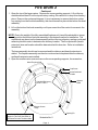
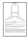
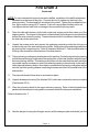
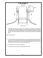
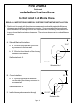
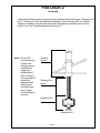
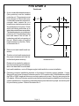
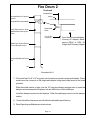
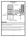
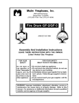
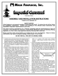
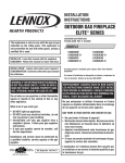
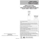
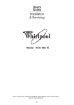
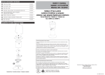
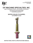
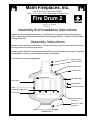
Malm Fireplaces, Inc.
368 Yolanda Avenue, Santa Rosa, CA 95404
(707) 523-7747 - Fax: (707) 571-8036 [email protected]
Fire Drum 2
Tested to U/L Standards
1482 and 737
Assembly And Installation Instructions
Read Instructions carefully before starting. Installation must comply with all local and national
codes. A building permit must be obtained before starting installation. All parts must be in place
or listing will be void.
Assembly Instructions
Remove and set aside the smaller carton. It is not necessary to open this carton before moving it.
It is now possible to open the larger carton.
Carefully unpack all parts from cartons as directed below carefully inspecting all parts. If any parts
are damaged or missing, contact shipper or dealer immediately.
Do not install unit using damaged parts.
Damper Section
Connector Shield
Top Metal Hood
Top Refractory
Fiberglass strip
Screen Hinge
Fiber Glass Strip
Optional Baffle
Baffle Spacer & Bolt
Screen
Side Wall Refractory Bricks
Screen Hinge
Groove in Bottom
Refractory
Bottom Fire - Bowl
Assembly
Illustration No. 1.
Fire Drum 2
Continued
1. Open the top of the larger carton. Remove the corner packing supports. Lift out the top
metal hood and then lift out the top refractory casting. Be careful not to drop this refractory
piece. Remove the center packing pad. It is not necessary to remove the bottom refractory casting from the fire-bowl assembly, this should remain in place in the bottom fire-bowl
assembly.
2. Lift out the bottom fire-bowl assembly or slit open one side of the carton for access to the
assembly.
NOTE: Due to the weight of the fully assembled fireplace unit it would be advisable to temporarily position the bottom fire-bowl assembly in the desired location for installation. The
metal hood may be set on the base assembly without the top refractory casting or side wall
refractory bricks in order to determine the chimney location. The floor protection (hearth
extension) size and location should be determined at this time also. Refer to installation
Instructions.
The base assembly should now be removed and the chimney and hearth extension installed. The fireplace assembly can then be continued and completed after the chimney
and hearth extension are installed.
3. Open the smaller carton now and remove the corner packing supports, the screen box,
Metal Fireplace Wall
Cap Screw
2
Spacer Bolt head
to inside
3
Optional
Baffle
Side Wall Refractory
Bricks 1 Thru 4
4
1
Bottom Screen
Hinge
Make Certain Fiberglass Strip Seal
Begins At This Point And Ends At
The Same Point On The Other Side
Opening Fin
Illustration No. 2
Page - 2
Fire Drum 2
Continued
Illustration No. 3
baffles (if this unit included the optional convection baffles), the damper housing carton and
the additional 9" X 24" connector flue pipe carton.
4. Refer to Illustrations No. 1 and No. 2 for identification of parts and relationships referred to
in these Assembly Instructions.
5. Carefully lift out the curved side wall refractory bricks. Place these aside for later installation. Please note the top and bottom of these bricks for proper installation later.
6. Now lift out the metal cylindrical fireplace wall (body section).
7. Place the body section on the fire-bowl assembly so that it is seated in the depressions
provided for in the refractory casting. Notice that other depressions are provided around
the circumference of the back of the fireplace for the bottom edge of the body section.
Make the body section seat into this groove. At this point the body section should be
seated into all the depressions, grooves, and slots provided for it in the refractory casting.
Page - 3
Fire Drum 2
Continued
NOTE: For units ordered with optional convection baffles, installation of the baffle attachment
hardware must be done at this point. Connect the four (4) spacers to the body in the
holes provided. The hex head bolt should be to the inside. Tighten the hex head bolt to a
firm, tight condition using a 9/16" wrench. If the unit is a porcelain finished unit do not
over tighten the hex head bolts or damage to the porcelain finish may result.
8.
Place the side wall refractory bricks back in the body section just as they came out of the
shipping carton. The tongue on the bottom of the bricks will fit into the groove provided in the
bottom fire bowl refractory casting. These bricks should all fit into place so that the tops of
the bricks are at the same level.
9.
Unpack the screen carton and remove the gasketing material provided into the groove
located in the top of the side wall refractory bricks. Begin placing the gasketing material at
the opening fins connection point. Refer to Illustration Number 2. Care should be taken to
fill the groove around the circumference of the body section.
10. The top refractory casting may now be placed into position. Rotate the top refractory casting
so that the positioning grooves match the opening fins of the metal fireplace wall and top of
the body opening channel. This casting must fit down into the metal fireplace wall, and slight
movement may be necessary to insure the refractory casting is down evenly on the tops of
all the side wall refractory bricks. Also check to see that the top refractory casting has seated
onto the top of the opening channel completing the seal around the full circumference of the
body section.
11. The top metal hood will now drop on and seat into place.
12. Unpack the damper housing (Part Number DH 2) which also contains the connector shield
(Part Number CS 2).
13. Place the connector shield in the upper refractory opening. Refer to the illustrated sheet
packed with the damper housing and the connector shield for the proper installation.
Refer to Illustration No. 3.
14. Seat the damper housing (the flue pipe section with the damper plate and handle) into the
Page - 4
Fire Drum 2
Continued
Illustration No. 4
metal hood collar making sure that the slots around the circumference of the pipe are
immediately above the collar of the fireplace unit. The damper plate contained in the damper
housing should now rotate at least 90 degrees. That is, from a horizontal position to a vertical
position. (The damper plate handle is fixed in the same relative position as the damper
plate.)
Refer to Illustration No. 4
15.
A screen is provided and should be left in place over the opening of the fireplace at all times
when in use. The screen is lifted into place in the opening and held by the screen hinge rod
attached to the frame of the screen. The screen hinge rod engages a hole on the left of the
body channel at the top and the body hinge slug at the bottom.
16. Your fireplace unit is now ready for installation.
17. Continue on to the next section. Read Installation Instructions.
Page - 5
Fire Drum 2
Continued
Installation Instructions
Do Not Install In A Mobile Home.
READ ALL INSTRUCTIONS CAREFULLY BEFORE STARTING THE INSTALLATION.
1. Position unit to comply with the minimum clearances to combustible materials. Minimum
clearances are shown from the chimney connector. It is recommended that no overhead
cross members in the ceiling or roof be cut. Reposition unit if necessary, being careful not
to move closer than the minimum clearances. The minimum clearances to combustibles are
as follows:
A. Side wall/Back wall Installation:
19 1/2"
a. 19 1/2 inches from the back of the chimney connector to the back wall.
b. 35 1/2 inches from the side of the chimney
connector to the side wall.
See Illustration No. 5.
35 1/2"
Illustration No. 5
B. Corner Installation:
23 1/2"
a. 23 1/2 inches minimum as measured
from the side of the chimney connector to
the nearest wall.
See Illustration No. 6.
2. Install chimney and accessories through
23 1/2"
Illustration No. 6
Page - 6
Fire Drum 2
Continued
ceiling and roof directly above unit per chimney manufacturer's instructions. Chimney must
be U.L. listed 8 inch Low Heat Residential Appliance Type Chimney (All Fuel). Before
Chimney is installed use a plumb-bob to assure that chimney is directly above the flue
outlet on unit. See Typical Installation Illustration No. 7.
Note: We do NOT
recommend use
of the 8 inch
chimney system
with elbowed
single-story
installations of
the Fire Drum 2,
as more height is
needed for
adequate draft.
Elbows aren't
normally necessary in single
story buildings in
any case.
Chimney
System
Chimney Connector
Fireplace Unit
Illustration No. 7
Page - 7
Fire Drum 2
Continued
3. A non-combustible hearth extension
(floor protector) must be installed
under the unit. This extension must
be a minimum of 3/8 inch thick noncombustable material such as brick,
concrete, slate, ceramic tile, or a
listed floor protection board such as
Wonderboard or Homosote. Check
with local building authorities as to
what other materials are acceptable.
The hearth extension must extend a
minimum of 5 1/2 inches beyond the
back and sides of the unit and 16
inches beyond the front opening of
the unit. Mark location of required
hearth extension on the floor. Refer
to Illustration No. 8.
5 1/2"
5 1/2"
5 1/2"
4. Remove unit and install hearth extension.
16"
5. Position unit on hearth extension at
the proper clearances with the flue
outlet directly below chimney.
Illustration No. 8
Rotate unit as needed to make certain front opening is positioned parallel to the back wall for a side wall/
back wall installation, or at a 45 degree angle to both walls for a corner installation.
6. Chimney connector installation depends on the brand of chimney system installed. If using
Simpson Dura-Vent a Universal Connector part No. 1870 must be used. With Metalbestos either
the DSA or DSAC single wall chimney connector part must be used. Security users require the
UP adapter. With most chimney systems manufactured a similar part is available from the chimney
system manufacturer. If necessary contact the chimney manufacturer for proper connection parts
for your chimney system. Refer to Illustration No. 8.
Page - 8
Fire Drum 2
Continued
Insulated Pipe
Insulated Class "A" Chimney
System
Ceiling
Single Wall Chimney Adapter
9" to 8" Slip Connector. Sheet
Metal Screw to Chimney Connector.
Sheet Metal
Screw
8" to 9" Slip
Connector
Middle Pipe Section Bottom
Fits Into Damper Section
Dura-Vent Universal Adapter,
Security UP Adapter, Metalbestos DSAC or DSA ,Or
Single Wall Chimney Adapter
Damper Pipe Bottom Fits Into
Unit
Unit
Illustration No. 8
7. First install the 8" to 9" x 18" long pipe over the chimney system's single wall adapter. Sheet
metal screw the connector to the single wall adapter using sheet metal screw in the holes
provided.
Slide the middle section of pipe over the 18" long pipe allowing enough room to insert the
damper section between the fireplace unit and the bottom of the middle pipe.
Install the damper section into the fireplace. Slide the middle pipe section into the damper
section.
8. Check that all the clearances are still within the allowable specifications.
9. Read Operating and Maintenance Instructions.
Page - 9
Fire Drum 2
Continued
2" Clearance From Studs
To Chimney Wall
Header
12" Of Brick From Liner
To Combustables
5/8" Fireclay Liner
Minimum or Equivalent
12" Minimum
Sill/Support
12" Minimum
MASONRY THIMBLE
Masonry Chimney
If using a masonry chimney, it must meet the minimum standards of the National Fire Protection
Association (NFPA) Standard 211. The chimney must have at least a 5/8" fire clay liner or a listed
chimney liner system. The chimney must be inspected for cracks, loose mortar, or any other signs of
deterioration. It is best to have the chimney inspected by a professional. Make certain the chimney
is cleaned prior to installation of this fireplace.
The size of the chimney should be between 36 and 96 square inches. Larger chimneys should be
relined to meet these requirements. Incorrect sizing of the chimney may affect the draft and result in
poor fireplace performance. Do not install more than one appliance to any chimney.
There are different accepted methods of connecting the fireplace to a masonry chimney through a
combustible wall. This type of installation requires the use of a thimble to protect the surrounding
combustible materials. Check with your local building officials or consult NFPA211.
Page - 10
Fire Drum 2
Continued
OPERATING INSTRUCTIONS
Failure to properly use and maintain this appliance may void the
manufacturer's warranty and could result in a house fire.
WARNING: This free standing fireplace is a heat producing appliance and may cause severe burns if touched. Keep
children away. Do Not over fire. If any portion of the unit or flue starts to glow you are over firing. This is a free standing
fireplace, do not use for any other purpose.
1. The first few fires should be small in order to properly cure the painted surfaces and refractory. During the first few
fires, some smoking may occur as the paint cures. You may wish to open a window to minimize discomfort during
this curing period.
2. DO NOT BURN TRASH OR GARBAGE IN THIS UNIT. When building a fire, be sure the damper is fully opened
and sufficient combustion air is available. Place dry kindling on dry wadded paper then ignite with a match. Add
progressively larger pieces of wood until the fire is well established. Leave the damper fully open. Close only after
the fire has burned out completely. Add additional firewood as needed to maintain the fire.
3. The fire screen must be in place during operations. WARNING: FIREPLACE STOVES EQUIPPED WITH DOORS
SHOULD BE OPERATED ONLY WITH DOORS FULLY OPEN OR DOORS FULLY CLOSED. IF DOORS ARE
LEFT PARTLY OPEN, GAS AND FLAME MAY BE DRAWN OUT OF THE FIREPLACE STOVE OPENING,
CREATING RISKS FROM BOTH FIRE AND SMOKE.
4. Keep the pipe damper in the full open position when the fireplace is being used.
5. CAUTION: Heating the air in a closed building decreases the relative humidity of the air, which will dry wood and
other combustible materials. This drying lowers the ignition temperature of these materials thus increasing fire
hazards. To reduce the risk of fire, some provision should be made for replenishing moisture to the air whenever
a structure is being heated for extended periods.
6. Be sure to provide combustion air into the dwelling when using this or any other wood burning appliance. A partially
open window or outside air register in the vicinity of the unit would be acceptable. Combustion air must be supplied
in conformance with the Uniform Mechanical Code.
7. CAUTION: NEVER USE GASOLINE, GASOLINE TYPE LANTERN FUEL, KEROSENE, CHARCOAL LIGHTER
FLUID, OR SIMILAR LIQUIDS TO START OR “FRESHEN UP” A FIRE IN THIS HEATER. KEEP ALL SUCH
LIQUIDS WELL AWAY FROM THE HEATER WHILE IN USE.
8. DISPOSAL OF ASHES: Ashes should be placed in a metal container with a tight fitting lid. The closed container
of ashes should be placed on a noncombustible floor or on the ground, away from all combustible materials, pending
final disposal. The ashes should be retained in the closed container until all cinders have thoroughly cooled.
9. READ MAINTENANCE INSTRUCTIONS.
IN CASE OF A CHIMNEY FIRE
A safe and correct installation and extra care will help prevent a fire, but accept the idea that there could be a fire. Be
prepared to handle it. Make certain everyone in the house is familiar with the warning signs of a chimney fire:
1. Call the Fire Department immediately, before doing anything else.
2. Discharge a dry chemical extinguisher into the fireplace opening. If an extinguisher is not available, toss baking soda
into the opening. Do not pour water on the fire.
3. Close all air intakes to the firebox and leave closed until the fireplace, stove or stove pipe is completely cooled.
4. Watch for sparks on the roof. If necessary, hose down the roof around the chimney. DO NOT pour water down or
on the chimney.
5. After the fire is completely out, inspect the chimney for any signs of damage. If you are not certain, have your local
Fire Department inspect the chimney for you.
6. Never use coal in a fireplace. Coal should be used only in stoves especially designed to burn coal. If the toxic gases
produced enter the room they can be fatal.
Page - 11
Fire Drum 2
Continued
MAINTENANCE INSTRUCTIONS
Failure to properly use and maintain this appliance may void the
manufacturer's warranty and could result in a house fire.
1. Always keep the area around the unit clean and clear of furniture and other objects. Keep all furniture a minimum
of 48 inches away from the heater.
2. Periodically the entire unit, chimney connector, and chimney system must be inspected for leaks, broken or
malfunctioning parts, and loose connections. If any problems are noted, contact your dealer for repair services. Do
not operate the unit until repairs have been completed.
CREOSOTE FORMATION AND THE NEED FOR REMOVAL.
When wood is burned slowly, it produces tar and other vapors, which combine with moisture to form creosote. Creosote
vapors condense in the relatively cool chimney flue, and creosote residue accumulates on the flue lining. When ignited,
this creosote can make an extremely hot fire. The chimney connector and chimney should be inspected at least twice
monthly during the heating season to determine if creosote buildup has occurred. If creosote has accumulated, it should
be removed to reduce the chance of a chimney fire.
HOW TO REMOVE CREOSOTE.
1. Clean the chimney with brushes and equipment available at local fireplace shops.
2. Chemical chimney cleaners are used by adding them to the fire, but they are not intended for use in chimneys
already containing heavy soot deposits. Rather, they are intended to inhibit soot buildup. They can be used
in metal chimneys provided the manufacturers instructions are strictly followed. Generally these commercial
cleaners are quite effective.
3. Call a professional chimney sweep in your area. They possess the experience and tools necessary to make
the task easy.
Maintenance other than the items specifically mentioned herein are to be performed by a qualified serviceman only.
Contact your dealer. For further information on using your heater safely, obtain a copy of the National Fire Protection
Association publication "Using Coal and Wood Stoves Safely," NFPA HS-10-1978. The address of the NFPA is
Batterymarch Park, Quincy, MA 02269. File these instructions for future reference.
NEVER STORE OR ALLOW PAPERS, KINDLING, FIREWOOD OR ANY OTHER
COMBUSTIBLES WITHIN 48 INCHES OF UNIT.
Malm Fireplaces, Inc.
368 Yolanda Avenue
Santa Rosa, Ca. 95404
707 523-7755 Fax: 707 571-8036
[email protected]
www.malmfireplaces.com