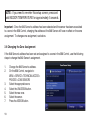
1
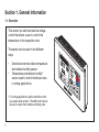
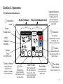
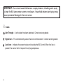
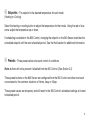
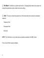
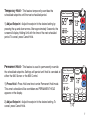
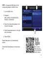
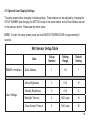
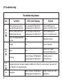
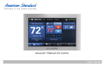
AZONE940AC52Z
Indoor Temperature
Humidity
PM
Outdoor
Hold
Heating
Heat to:
Home
Following Schedule
Scan to see
installation and
help videos for
the 940 Sensor.
Cooling
Clean
Screen
Away
Communicating
Sensor
with
Display
Sleep
Zone
Fan
Auto
Auto
Table of Contents
Overview.............. 2
Operation............. 3
Installation......... 11
User &
Installation
Guide
Section 1. General Information
1.1 Overview
This sensor is a wall mounted low voltage
control that allows a user to control the
temperature in the respective zone.
The sensor can be used in two different
ways:
•
•
Stand-alone remote indoor temperature
and relative humidity sensor.
Temperature and relative humidity*
sensor used to control individual zones
in zoning applications.
* For zoning applications, relative humidity control
is a system-level function. The 950 Control allows
the user to select the humidity-controlling zone.
2
Section 2. Operation
Display Selection
2.1 Buttons and Indicators
1 Notification
Icons
Room
Temperature
System Status
Indoor Temperature
Indoor
Relative
Humidity
Humidity
PM
Current
Time
Outdoor Sensor
Displays Outdoor
Temperature or
Humidity if available.
Touch to alternate.
Outdoor
Hold
Hold
5
Maintains the
current setpoints
permanently or until
a chosen time.
Cooling
Heating
Clean
Screen
Clean Screen
When touched, the
unit ignores input for
30 seconds so the
screen can be wiped
with a damp cloth.
2 Setpoints
The desired
temperature the system
is targeting. Set
manually or by preset.
Heat to:
Home
Following Schedule
(from 950 Control)
Setpoints/Adjustments
Selecting Cooling or
Heating shows the
setpoint and allows
manual temperature
adjustment.
Away
Sleep
Zone
Fan
Auto
Auto
Zone Mode
The mode can be
set to Auto, Cool,
Heat or Off.
3 Presets
One-touch buttons
allow quick access to
preset values.
Fan Mode
4
The fan mode can
be set to Auto or On.
3
IMPORTANT: Do not use household cleaners or spray cleaners, including water spray
to clean the 940 zone sensor screen or enclosure. Household cleaners and sprays may
cause permanent damage to the zone sensor.
1 Icons
Alert Triangle – A critical alert has been detected. Contact servicing dealer.
Signal Icon – The communicating sensor has lost communication. Contact servicing dealer.
Lock Icon – Indicates the screen has been locked by the 950 Control. When this lock is
present, the sensor will not respond to any keypad presses.
4
2 Setpoints - The setpoint is the desired temperature for each mode
(Heating or Cooling).
Select the heating or cooling button to adjust the temperature for that mode. Using the red or blue
arrow, adjust the temperature up or down.
If scheduling is enabled on the 950 Control, changing the setpoint on the 940 Sensor overrides the
scheduled setpoint until the next scheduled period. See the Hold section for additional information.
3 Presets - Three presets allow one-touch control of conditions.
Note: buttons will not be present if disabled from the 950 Control. (See Section 2.2)
These preset buttons on the 940 Sensor are configured from the 950 Control and allow one-touch
convenience for the common situations of Home, Away or Sleep.
These preset values are temporary and will revert to the 950 Control’s scheduled settings at its next
scheduled period.
5
4 Fan Mode - Fan Mode is a system-level function.
Changing the fan mode at any sensor will
change the system fan mode to reflect the last fan setting.
5 Hold - This sensor offers three variations of Hold functionality that override the scheduled
setpoints.
Temporary Hold
Permanent Hold
Hold Until
NOTE: The Hold button is only visible when a schedule is enabled on the 950 Control.
Press Cancel Hold to resume schedule.
6
Temporary Hold - This feature temporarily overrides the
scheduled setpoints until the next scheduled period.
Indoor Temperature
Humidity
1) Adjust Setpoint - Adjust the setpoint to the desired setting by
pressing the up and down arrows. After approximately 5 seconds, the
screen will display Holding Until with the time of the next scheduled
period. To cancel, press Cancel Hold.
Permanent Hold - This feature is used to permanently override
the scheduled setpoints. Settings will persist until hold is canceled at
either the 940 Sensor or the 950 Control.
1) Press Hold - Press Hold one time to enter Permanent Hold mode.
This zone’s schedule will be overridden and PERMANENT HOLD
appears on the display.
2) Adjust Setpoint - Adjust the setpoint to the desired setting. To
cancel, press Cancel Hold.
1
Cooling
Heating
Heat to:
Holding Until:
PM
Outdoor
Cancel
Hold
Home
Hold
Indoor Temperature
Humidity
Clean
Screen
Away
Zone
Heat
Sleep
Fan
Auto
2
Cooling
Heating
Heat to:
Permanent Hold
PM
Outdoor
Cancel
Hold
Home
Hold
Clean
Screen
Away
Sleep
Zone
Fan
Auto
Auto
1
7
Hold Until - This feature overrides the scheduled setpoint until a user selected time is reached.
1) Press Hold Two Times - Press Hold two times to enter Hold Until
mode.
2
Indoor Temperature
Humidity
2) Adjust Setpoint - Adjust the setpoint to the desired setting.
3) Set End Time - Set the time to return to the scheduled setpoints. 3
The screen will show Holding Until with the selected time. To cancel,
press Cancel Hold.
When a 940
Sensor is following a schedule, the screen
will appear in
this manner.
8
Indoor Temperature
Humidity
PM
Cooling
Home
Following Schedule
Outdoor
Hold
Heating
Heat to:
Clean
Screen
Away
Zone
Heat
Sleep
Fan
Auto
Heating
Holding Until:
PM
Outdoor
Cancel
Hold
Home
Hold
1
Normal
Operation
Cooling
Heat to:
Clean
Screen
Away
Zone
Heat
Sleep
Fan
Auto
2.2 940 Sensor’s Screen Layout
The screen layout of the 940 Sensor can be
customized through the 950 Control.
MENU > SETTINGS >
SCREEN SETTINGS > ZONE SENSOR
Select the desired display settings. These
settings will update on the 940 Communicating
Sensor after selecting APPLY.
9
NOTE: If a zone without a 940 Communicating
Sensor is currently displayed, the following screen
will appear. Please note the zone in the top left.
Press either of the green arrows to switch to the
appropriate zone.
10
Section 3. Installation
3.1 Contents and Specifications
The following parts are included in product
model AZONE940AC52Z:
1 - Communicating Sensor
1 - Base
2 - Mounting screws/anchors
1 - Installation/User’s Guide
Specification
Description
Product Model:
AZONE940AC52Z
Product:
AccuLink™ Communicating Sensor
Size:
5.5” width x 3.4” height x 1.1” depth
Storage Temperature:
-40°F to 170°F, 0% - 95% RH
Operating Temperature:
32°F - 120°F, 5% - 90% RH non-condensing
Power:
24 VAC from HVAC System (Range: 18-32 VAC)
Power Consumption:
2 VA
Wire usage:
Minimum 18 gauge NEC approved control wiring
Scan to see a
video on installing
and setting up the
940 Zone Sensor.
11
3.2 Zone Sensor Location Considerations
The 940 Communicating
Sensor is designed for installation in climate controlled
living spaces.
It is recommended to place
the sensor in central locations with good circulation.
Avoid exterior walls and
areas too near windows,
doors, vents or concealed
pipes or chimneys.
Important: If an air source
is directed at or above the
sensor, heat from the screen
can be trapped within the
sensor body and can cause
the indoor temperature to be
biased.
12
2 FEET
Optimum
Zone
5 FEET
3.3 Physical Mounting
Remove cover by grasping at edges and
gently pulling the cover straight towards
you. It should release without much effort.
Be sure wires are routed through the center
of the base plate and are long enough to
connect to terminals.
For convenience multiple hole patterns are
provided. Select and mark two opposing
holes. A level may be used to ensure accuracy.
D
R
B
13
Mounting to studs:
Drill 1/8” pilot holes in the 2 locations
marked above.
OR
Mounting to drywall:
Drill 3/16” pilot holes for anchors (included
with the control) in the 2 locations marked
above.
Gently tap anchors into the holes.
D
R
DRILL HOLES
1/8” for screws
into studs
3/16” for drywall
anchors
14
B
Attach base to wall using 2 screws
provided. Do not overtighten.
3.4 Wiring
Connect power leads to the D, R and B
terminals.
• Wire data to D.
• Wire 24 VAC hot to R.
• Wire common to B.
D
B
R
Seal
Hole
NOTE: All wall penetrations MUST be
sealed to prevent temperature biasing.
! WARNING
▲
This information is intended for use by individuals possessing
adequate backgrounds of electrical and mechanical experience. Any attempt to repair a central air conditioning product
may result in personal injury and/or property damage. The
manufacture or seller cannot be responsible for the interpretation of this information, nor can it assume any liability in
connection with its use.
! CAUTION
▲
CAUTION: EQUIPMENT DAMAGE HAZARD - Improper wiring
can lead to equipment damage. Follow the terminal connection
information carefully to ensure the control is wired properly. After wires are secure, bare wires MUST NOT touch each other.
See the Field Wiring Diagrams for specific system applications.
! WARNING
▲
LIVE ELECTRICAL COMPONENTS! - During installation,
testing, servicing, and troubleshooting of this product, it may
be necessary to work with live electrical components. Failure
to follow all electrical safety precautions when exposed to live
electrical components could result in death or serious injury.
15
3.5 Setting Zone Address
Indoor Temperature
Setting up the 940 Sensor is a two-step process.
2
1
System Zone
Setup Number
BOTH steps MUST be performed.
Setting
STEP 1 – Setting the 940 Sensor’s address:
1. Verify that the Setup Number is “1” and if not
adjust it using red/blue arrows.
2. Select SYSTEM ZONE address by adjusting
with black arrows. SETTING display will not
adjust until setting is accepted below.
3. Pressing DONE saves changes and exits the
setup screen.
16
Cancel
Hold
Done
Clean
Screen
3
At initial power-up, the 940 Sensor Setup
Screen (shown above) will automatically
appear.
To re-enter the setup screen, press and hold
INDOOR TEMPERATURE for approximately
five seconds.
STEP 2 – Assigning the 940 Sensor to the
corresponding damper in the 950 Control.
1
2
1. Go to the 950 Control
2. Navigate to:
MENU > SERVICE > TECHNICIAN ACCESS >
PROCEED > ZONE SENSORS.
3. Select the corresponding damper on the
left side of the screen.
4. Select the appropriate sensor on the right
side of the screen
3
5. Press ASSIGN.
Repeat these steps for all communicating
sensors.
See the Zone Panel literature for more information.
Scan to see a
video on how to
set up zoning with
the 940 Sensor.
17
NOTE: If you need to re-enter this setup screen, press and
hold INDOOR TEMPERATURE for approximately 5 seconds.
Important: Once the 940 Sensor’s address has been selected and the sensor has been associated
to a zone in the 950 Control, changing the address at the 940 Sensor will have no effect on the zone
assignment. To change zone assignment, see below.
3.6 Changing the Zone Assignment
If the 940 Sensor’s address has been set and assigned to a zone in the 950 Control, use the following
steps to change the 940 Sensor’s assignment.
1.
2.
3.
4.
5.
6.
7.
18
Change the 940 Sensor’s address.
On the 950 Control, navigate to:
MENU > SERVICE > TECHNICIAN ACCESS >
PROCEED > ZONE SENSORS
Select the appropriate zone.
Select the UNASSIGN button.
Select the new zone.
Select the sensor.
Press the ASSIGN button.
3.7 Optional User Display Settings
The setup screen allows changing of display settings. These features can be adjusted by changing the
SETUP NUMBER and changing the SETTING range in the same manner as the Zone Address was set
in the previous section. Please see the matrix below.
NOTE: To enter this setup screen, press and hold INDOOR TEMPERATURE for approximately 5
seconds.
940 Sensor Setup Table
Setup
Number
Setting
Range
Default
Setting
Zone Address
1
1-8
1
Active Brightness
2
0-10
10
Standby Brightness
3
0-10
0
Backlight Timeout
4
5-60 (sec)
10
Clean Screen Timeout
5
5-60 (sec)
30
Data
ONLY for Installers
User Settings
19
3.8 Troubleshooting
Troubleshooting Issues
Icon
Alert
Icon
Signal
Icon
Lock
Icon
NA
20
Condition
950 Control Displays
Solution
Indoor temperature sensor
has failed/stopped reporting
An associated SOP.004.00 will
be displayed on the 950 control
Use the 950 Diagnostic
screen to troubleshoot alert
Indoor humidity sensor has
failed/stopped reporting
An associated SOP.004.03 will
be displayed on the 950 control
Use the 950 Diagnostic
screen to troubleshoot alert
One of the keypad segments
is stuck
NA
Replace the sensor
Hidden
NA
Normal Operation
Solid
NA
Sensor has not been
discovered by 950 control
Flashing
After 2 minutes, SOP.004.00 will
be displayed on the 950 control
Indicates a loss of
communications
Indicates the screen has been locked by the 950 control. When this lock is present, the sensor will
not respond to any keypad presses.
No display
After 2 minutes, SOP.004.00 will
be displayed on the 950 control
24VAC Power is lost on the
940 Sensor
BASE LIMITED WARRANTY
Subject to the terms and conditions of this limited warranty, Trane U.S., Inc. (“Company’) extends a limited warranty against manufacturing defects for the product(s) identified in
Tables 1, 1A, 1B attached hereto (“Products’) that are installed in a residential/multi-family application (personal, family or household purposes) under normal use and maintenance in the
United States and Canada.
This limited warranty applies to Products manufactured on or after August 1, 2011.
In order to maximize the available benefits under this limited warranty, the Purchaser (as defined below) should read it in its entirety. All repairs of Product parts covered under
this limited warranty must be made with authorized service parts and by a licensed HVAC service provider. Additionally, commercial applications are treated differently under this limited
warranty as stated in Tables 1, 1A, 1B attached hereto. For purposes of this limited warranty, “commercial applications” shall mean any application other than for personal, family, or
household use.
TERM: The limited warranty period for Products is as stated in Tables 1, 1A, 1B attached hereto. If the Purchaser properly registers the Products, the limited warranty period
shall be extended as stated in Tables 1, 1A, 1B attached hereto. Regardless of registration, the Commencement Date for a limited warranty period shall be the date that the original
installation is complete and all Product start-up procedures have been properly completed and verified by an installer’s invoice. If the installation and start-up date cannot be verified by
the installer’s invoice, the Commencement Date shall be sixty (60) days after the factory manufacture date which is verified by the Product serial number. Where a Product is installed in a
newly constructed home, the Commencement Date is the date the Purchaser purchased the residence from the builder. Proof of Product purchase, installation, and/or closing date of the
residence may be required to confirm the Commencement Date.
The installation of Product replacement parts under this limited warranty shall not extend the original warranty period. The warranty period for any Product part replaced under this
limited warranty is the applicable warranty period remaining under the original Product warranty.
WHO IS COVERED: This limited warranty is provided only to the original owner and his or her spouse (“Purchaser’) of the residence where the Products are originally installed.
This warranty is not transferable except according to terms stated on the applicable website identified below under Registration Requirements. Company has the right to request any and
all proof of Product purchase or installation and/or closing date of the residence.
WHAT COMPANY WILL DO: Company may request proof of Product purchase and/or installation in order to provide Product parts under this limited warranty. As Company’s only
responsibility and Purchaser’s only remedy under this limited warranty, Company will furnish a replacement part to the licensed HVAC service provider, without charge for the part only, to
replace any Product part that fails due to a manufacturing defect under normal use and maintenance. The Purchaser must pay for any and all shipping and handling charges and other
costs of warranty service for the replacement part. If a Product part is not available, Company will, at its option, provide a free suitable substitute part or provide a credit in the amount of
the then factory selling price for a new suitable substitute part to be used by the Purchaser towards the retail purchase price of a new Company product. Any new Product purchase shall
be at Purchaser’s sole cost and expense including, but not limited to, all shipping, removal, and installation costs and expenses.
REGISTRATION REQUIREMENTS: All Products must be properly registered online by the Purchaser within sixty (60) days after the Commencement Date to receive the
registered limited warranty terms. To register online, go to:
http://www.trane.com/Residential/For-Owners/Warranties or
http://www.americanstandardair.com/servicesupport/pages/warranty.aspx
and click “Begin Online Registration.” If a Purchaser does not register within this stated time period, the base limited warranty terms shall apply.
21
ELIGIBILITY REQUIREMENTS: The following items are required in order for the Products to be covered under this limited warranty:
• The Products must be in the same location where they were originally installed.
• The Products must be properly installed, operated, and maintained by a licensed HVAC service provider in accordance with the Product specifications or installation, operation,
and maintenance instructions provided by Company with each Product. Failure to conform to such specifications and/or instructions shall void this limited warranty. Company
may request written documentation showing the proper preventative maintenance.
• All Product parts replaced by Company under this limited warranty must be given to the servicing provider for return to Company.
• Air handlers, air conditioners, heat pumps, cased or uncased coils and stand-alone furnaces must be part of an Air Conditioning, Heating, and Refrigeration Institute rated and
matched system or a specification in a Company provided bulletin or otherwise approved in writing by a Company authorized representative.
EXCLUSIONS: The following are not covered by this limited warranty:
• Labor costs including, but not limited to, costs for diagnostic calls or the removal and reinstallation of Products and/or Product parts.
• Shipping and freight expenses required to ship Product replacement parts.
• Failures, defects, or damage (including, but not limited to, any loss of data or property) caused by (1) any third party product, service, or system connected or used in conjunction
with the Products; (2) any use that is not designed or intended for the Products; (3) modification, alteration, abuse, misuse, negligence, or accident; (4) improper storage, installation, maintenance, or operation including, but not limited to, operation of electrical equipment at voltages other than the range specified on the Product nameplate; (5) any use in
violation of written instructions or specifications provided by Company; (6) any acts of God including, but not limited to, fire, water, storms, lightning, or earthquakes; or any theft
or riots; or (7) a corrosive atmosphere or contact with corrosive materials such as, but not limited to, chlorine, fluorine, salt (provided that indoor and outdoor coils will only be
covered if a Sea Coast Kit is installed), sulfur, recycled waste water, urine, fertilizers, rust, or other damaging substances or chemicals.
• Products purchased direct including, but not limited to, Internet or auction purchases and purchases made on an uninstalled basis.
• Cabinets or cabinet pieces that do not affect product performance, air filters, refrigerant, refrigerant line sets, belts, wiring, fuses, surge protection devices, non-factory installed
driers, and Product accessories (unless otherwise specified).
• Increased utility usage costs.
REFRIGERANT POLICY: (1) Manufacturer-Installed Refrigerant: Beginning on January 1, 2010, R-22 refrigerant will no longer be used as a manufacturer-installed
refrigerant as required by federal regulation. All Products with manufacturer-installed refrigerant will include R410-A refrigerant. Any and all expenses or costs associated with
replacing Product parts that are not R-410A compatible will not be covered by the terms and conditions of this limited warranty. (2) Non-Manufacturer installed Refrigerant: For
Products manufactured and sold by the Company without refrigerant, only manufacturer approved and genuine alternate refrigerants shall be used. The use of contaminated,
counterfeit, non-genuine, or non-manufacturer approved alternate refrigerant will void this limited warranty. (3) All Products: Products include a liquid line filter drier which
must be replaced when a compressor replacement is necessary. A suction line filter drier must be added for compressors defined as burnouts and failure to do so will void
this warranty. Non-approved refrigerant and/or non-approved refrigerant system additives including, but not limited to dyes will void this limited warranty.
22
ADDITIONAL TERMS:
THIS LIMITED WARRANTY AND LIABILITY SET FORTH HEREIN ARE IN LIEU OF ALL OTHER WARRANTIES AND LIABILITIES, WHETHER IN CONTRACT OR IN
NEGLIGENCE, EXPRESS OR IMPLIED, IN LAW OR IN FACT. THE IMPLIED WARRANTIES OF MERCHANTABILITY AND FITNESS FOR A PARTICULAR PURPOSE ARE LIMITED
TO THE DURATION OF THE APPLICABLE PRODUCT WARRANTY. COMPANY DOES NOT AUTHORIZE ANY PERSON TO CREATE FOR IT ANY OBLIGATION OR LIABILITY IN
CONNECTION WITH THE PRODUCTS.
NOTWITHSTANDING ANYTHING IN THIS LIMITED WARRANTY TO THE CONTRARY, COMPANY SHALL NOT BE LIABLE FOR ANY INCIDENTAL, CONSEQUENTIAL, INDIRECT, SPECIAL AND/OR PUNITIVE DAMAGES, WHETHER BASED ON CONTRACT, WARRANTY, TORT (INCLUDING, BUT NOT LIMITED TO, STRICT LIABILITY OR NEGLIGENCE),
PATENT INFRINGEMENT, OR OTHERWISE, EVEN IF ADVISED OF THE POSSIBILITY OF SUCH DAMAGES. COMPANY’S MAXIMUM LIABILITY HEREUNDER IS LIMITED TO THE
ORIGINAL PURCHASE PRICE OF THE PRODUCTS.
No action arising out of any claimed breach of this limited warranty may be brought by a Purchaser more than one (1) year after the cause of action has arisen.
This limited warranty gives you specific legal rights, and you may also have other rights as otherwise permitted by law. If this Product is considered a consumer product, please be
advised that some local laws do not allow limitations on incidental or consequential damages, how long a warranty lasts based on registration, or how long an implied warranty lasts, so that
the above limitations may not fully apply. Refer to your local laws for your specific rights under this limited warranty.
Residential Systems
6200 Troup Highway, Tyler, TX 75707
Attn: Customer Relations
Or visit our website at www.trane.com or www.americanstandardair.com
GW-658-4212
23
Table 1A: Warranty Time Periods
COVERAGE TERMS FOR RESIDENTIAL APPLICATIONS: Pursuant to the Trane U.S., Inc. (“Company”) limited warranty terms and
conditions, the following Products are covered for the base time periods as stated below (“Base Limited Warranty period”). If registered, the
Base Limited Warranty Periods for certain products will be extended as stated below (“Registered Limited Warranty Period”).
CONTROLS: *CONT200,*CONT401,*CONT402, *CONT600 &*CONT602
Base Limited Warranty Period: one (1) year | Registered Limited Warranty Period: five (5) years
CONTROLS: *ZEMT500, CONT624, *CONT800,*CONT802,*CONT803,*CONT 824, *CONT900, *ZONE940, *ZONE950
Base Limited Warranty Period: five (5) years | Registered Limited Warranty Period: ten (10) years
ZONING PRODUCTS: *ZONE950, *ZONE940, *ZONE930, ZZONEPNLAC52Z, ZZONEEXPAC52Z,
ZZSENSAL0400, BAYSEN01ATEMPA, BAY24VRP, ZDAMPRD, ZDAMPSM, ZDAMPBM, ZDAMPRR
Base Limited Warranty Period: five (5) years | Registered Limited Warranty Period: ten (10) years
HUMIDIFIERS: *HUMD200, *HUMD300 & *HUMD500
Base Limited Warranty Period: five (5) years | Registered Limited Warranty Period: ten (10) years
ENERGY RECOVERY VENTILATOR (ERV): *ERVR100, *ERVR200 & *ERVR300
Base Limited Warranty Period: five (5) years | Registered Limited Warranty Period: ten (10) years
AIR CLEANERS: TFD & AFD
Base Limited Warranty Period: five (5) years | Registered Limited Warranty Period: ten (10) years
VARIABLE SPEED OIL FURNACE: *HV-V, *LF-V, *LR-V,*DF-V
Base Limited Warranty Period: Parts- five (5) years, Heat Exchanger - twenty (20) years
Registered Limited Warranty Period: Parts - ten (10) years, Heat Exchanger - Lifetime
NON-VARIABLE SPEED OIL FURNACE: *HV, *LF, *LR,*DF
Base Limited Warranty Period: Parts- five (5) years, Heat Exchanger - twenty (20) years
Registered Limited Warranty Period: Parts - five (5) years, Heat Exchanger - Lifetime
SPECIFIC TERMS FOR COMMERCIAL APPLCIATIONS:
Base Limited Warranty Period Applies for all controls, zoning products, humidifiers and ERV’s
All Oil Furnaces: Parts - one (1) year, Heat Exchanger - twenty (20) years
*(First letter may be A or T)
6200 Troup Highway
Tyler, TX 75707
© 2013 American Standard Heating & Air Conditioning
24
11-HD11D1-2
01/13