1
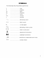
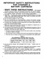
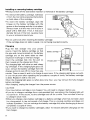
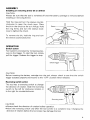
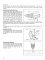
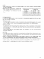
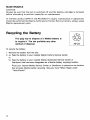
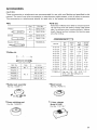
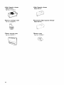
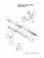
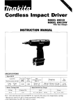
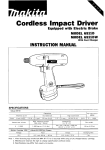
Equipped with Electric Brake
MODEL 6223DE
MODEL 6223DWE
With Fast Charger
INSTRUCTION MANUAL
SPECIFICAT10 NS
Capacities
Steel
10 mm
(318")
9
Wood
I
15 mm
1518")
Wood screw
I
5.1 mm x 35 mm
13/16" x 1-318")
Battery Cartridge 1220
Dimensions
IRPM)
iL x W x HI
Net
weight
I
6 m m 1114")
202 mm x 94 mm x 221 mm
17-15/16" x 3-11/16" x 8-3/4'1
1.5 kg
(3.1 lbsl
I
~
700
1
Model DC1290 Fast Charger
Voltage
12 v
No load speed
Machine screw
Input
1
A.C. only 50 Hz - 60 Hz
output
1
D.C.9.6 V, 12 V
Charging time
1
* Manufacturer reserves the right t o change specifications without notice.
* Note: Specifications may differ from country to country.
WARNING: For your personal safety, READ and UNDERSTAND before using.
SAVE THESE INSTRUCTIONS FOR FUTURE REFERENCE.
1 Hr.
GENERAL SAFETY RULES
(For All Battery Operated Tools)
WARNING! Read and understand all instructions. Failure
to follow all instructions listed below, may result in electric
shock, fire and/or serious personal injury.
SAVE THESE INSTRUCTIONS
Work Area
Keep your work area clean and well lit. Cluttered benches and dark areas invite
accidents.
Do n o t operate power tools in explosive atmospheres, such as in the presence
of flammable liquids, gases, or dust. Power tools create sparks which may ignite
the dust or fumes.
Keep bystanders, children, and visitors away while operating a power tool.
Distractions can cause you t o loose control.
Electrical Safety
A battery operated tool w i t h integral batteries or a separate battery pack must
be recharged only w i t h the specified charger for the battery. A charger that
may be suitable for one type of battery may create a risk of fire when used w i t h
another battery.
Use battery operated tool only w i t h specifically designated battery pack. Use
of any other batteries may create a risk of fire.
Personal Safety
.Stay alert, watch w h a t you are doing, and use common sense when operating
a power tool. Do not use tool while tired or under the influence of drugs, alcohol,
or medication. A moment of inattention while operating power tools may result
in serious personal injury.
Dress properly. Do not wear loose clothing or jewelry. Contain long hair. Keep
your hair, clothing, and gloves away from moving parts. Loose clothes, jewelry,
or long hair can be caught in moving parts.
Avoid accidental starting. Be sure s w i t c h is in the locked or o f f position before
inserting battery pack. Carrying tools with your finger on the switch or inserting
the battery pack into a tool with the switch on invites accidents.
Remove adjusting keys or switches before turning the tool on. A wrench or
a key that is left attached to a rotating part of the tool may result in personal injury.
Do not overreach. Keep proper footing and balance at all times. Proper footing
and balance enable better control of the tool in unexpected situations.
Use safety equipment. Always wear eye protection. Dust mask, nonskid safety
shoes, hard hat, or hearing protection must be used for appropriate conditions.
Tool Use and Care
Use clamps or other practical way t o secure and support the workpiece t o a
stable platform. Holding the work by hand or against your body is unstable and
may lead t o loss of control.
Do not force tool. Use the correct tool for your application. The correct tool
will do the job better and safer at the rate for which it is designed.
* D o not use tool if s w i t c h does not turn it on or off. A tool that cannot be
controlled with the switch is dangerous and must be repaired.
-Disconnect battery pack from tool or place the switch in the locked or off
position before making any adjustments, changing accessories, or storing the
tool. Such preventive safety measures reduce the risk of starting the tool
accidentally.
Store idle tools out of reach of children and other untrained persons. Tools are
dangerous in the hands of untrained users.
When battery pack is n o t in use, keep it away from other metal objects like:
paper clips, coins, keys, nails, screws, or other small metal objects that can
make a connection from one terminal t o another. Shorting the battery terminals
together may cause sparks, burns, or a fire.
Maintain tools w i t h care. Keep cutting tools sharp and clean. Properly maintained
tools with sharp cutting edge are less likely t o bind and are easier t o control.
Check for misalignment or binding of moving parts, breakage of parts, and any
other condition that may affect the tool's operation. I f damaged, have the tool
serviced before using. Many accidents are caused by poorly maintained tools.
Use only accessories that are recommended by the manufacturer for your
model. Accessories that may be suitable for one tool may create a risk of injury
when used o n another tool.
Service
Tool service must be performed only by qualified repair personnel. Service or
maintenance performed by unqualified personnel may result in a risk of injury.
When servicing a tool, use only identical replacement parts. Follow instructions
i n the Maintenance section of this manual. Use of unauthorized parts or failure
t o follow Maintenance Instructions may create a risk of shock of injury.
3
Specific Safety Rules
1. Hold tool by insulated gripping surfaces when performing an operation where
the cutting tool may contact hidden wiring. Contact with a "live" wire will
also make exposed metal parts of the tool "live" and shock the operator.
2. Be aware that this tool is always in an operating condition, because it does
not have t o be plugged into an electrical outlet.
3.Always be sure you have a firm footing.
Be sure no one is below when using the tool in high locations.
4. Hold the tool firmly.
5. Keep hands away from rotating parts.
6. Do not leave the tool running. Operate the tool only when hand-held.
7. Do not touch the drill bit or the workpiece immediately after operation; they
may be extremely hot and could burn your skin.
4
SYMBOLS
The followings show the symbols used for tool
.................................
volts
...............
amperes
.................................
herts
................
kilograms
.................................
hours
................... minutes
............ seconds
.................................
alternating current
_._.
direct current
.................................
no load speed
.................................
alternating or direct current
.................................
Class II Construction
.................................
splash-proof construction
.................................
watertight construction
................................
revolutions or reciprocation per minute
.................................
number of blow
5
IMPORTANT SAFETY INSTRUCTIONS
FOR CHARGER &
BATTERY CARTRlDGE
I.
SAVE THESE INSTRUCTIONS - This manual
Length of Cord (Feet)
AWG Size of Cord
25
18
50
18
100
18
150
16
9. Do not operate charger w i t h damaged cord or plug - replace them immediately.
IO. Do not operate charger if it has received a sharp blow, been dropped,
or other-
wise damaged in any way; take it t o a qualified serviceman.
1 1 . Do not disassemble charger or battery cartridge; take it t o a qualified
serviceman when service or repair is required. Incorrect reassembly may
result in a risk of electric shock or fire.
12.To reduce risk of electric shock, unplug charger from outlet before attempting any maintenance or cleaning. Turning off controls will not reduce this risk.
6
ADDITIONAL SAFETY RULES
FOR CHARGER & BATTERY CARTRIDGE
1. Do n o t charge Battery Cartridge when temperature is BELOW 10°C (5OOF)
or ABOVE 4OoC (104OF).
2. Do not attempt t o use a step-up transformer, an engine generator or DC power
receptacle.
3.Do n o t allow anything t o cover or clog the charger vents.
4. Always cover the battery terminals w i t h the battery cover w h e n the battery
cartridge is n o t used.
5. A battery short can cause a large current flow, overheating, possible burns
and even a breakdown.
(1) Do n o t touch the terminals with any conductive material.
(2) Avoid storing battery cartridge in a container with other metal objects such
as nails, coins, etc.
(3)Do n o t expose battery cartridge t o water or rain.
6. Do n o t store the tool and Battery Cartridge in locations where the temperature may reach or exceed 5OoC (122OF).
7. Do not incinerate the Battery Cartridge even if it is severely damaged or is
completely worn out. The battery cartridge can explode in a fire.
SAVE THESE INSTRUCTIONS.
7
Installing or removing battery cartridge
*Always switch off the tool before insertion or removal of the battery cartridge
*To remove the battery cartridge, withdraw
it from the tool while pressing the buttons
on both sides of the cartridge.
*To insert the battery cartridge, align the
tongue on the battery cartridge with the
groove in the housing and slip it into place.
Always insert it all the way until it locks in
place with a little click. If not, it may accidentally fall out of the tool, causing injury
to you or someone around you.
*Do not use force when inserting the battery cartridge.
If the cartridge does not slide in easily, it is not being inserted correctly.
Charging
Plug the fast charger into your power
source. Insert the battery cartridge so that
the plus and minus terminals on the battery
cartridge are on the same sides as their
respective markings on the fast charger.
Insert the cartridge fully into the port so
that it resets on the charger port floor.
The charging light will come on and charging will begin. If the charging light goes out
soon, remove the battery cartridge from the
charger and let it cool off for more than one
minute, Then re-insert it and try to charge it once more. If the charging light goes out within one minute even after repeating this procedure a couple of times, the battery cartridge
is dead. Replace it with a new one.
When the charging light goes out after about one hour, you may remove the fully charged
battery cartridge.
After charging, unplug the charger from the power source.
CAUTION:
*Your new battery cartridge is not charged. You will need to charge it before use.
*If you try to charge a cartridge from a just-operated tool, sometimes the charging light will
not come on. If this occurs, let the cartridge cool off for a while. Then re-insert it and try
to charge it once more.
*When you charge a new battery cartridge or a battery cartridge which has not been used
for a long period, it may not accept a full charge. This is a normal condition and does not
indicate a problem. You can recharge the battery cartridge fully after discharging it almost
completely a couple of times.
*If you wish to charge two battery cartridges, allow 15 minutes between chargings on the
fast charger.
8
ASSEMBLY
Installing or removing driver bit or drill bit
CAUTlON :
Always be sure that the tool is switched off and the battery cartridge is removed before
installing or removing the bit.
Hold the ring and turn the sleeve counterclockwise to open the chuck jaws. Place
the bit in the chuck as far as it will go. Hold
the ring firmly and turn the sleeve clockwise to tighten the chuck.
To remove the bit, hold the ring and turn
the sleeve counterclockwise.
OPERATION
Switch action
Tool speed is increased by increasing pressure on the trigger. To start the tool, simply
pull the trigger. Release the trigger to stop.
CAUTION:
Before inserting the battery cartridge into the tool, always check to see that the switch
trigger actuates properly and returns to the “OFF” position when released.
Reversing switch action
This tool has a reversing switch to change
the direction of rotation Slide the reversing
switch to the left for clockwise rotation or
to the right for counterclockwise
CAUTION
*Always check the direction of rotation before operation
*Move the reversing switch only after the tool comes to a complete stop Changing the
direction of rotation before the tool stops may damage the tool
9
CAUTION:
Always withdraw the tool from the workpiece before resuming operation. If the tool cannot be withdrawn, hold the tool firmly when turning on the tool, to overcome a strong
reaction
Adjusting the fastening torque
The fastening torque can be adjusted in six
stages by turning the adjusting ring so that
the pointer on the adjusting ring points to a
number on the tool body. The fastening
torque is minimum when the pointer points
to the number 1 and maximum when it
points to the at- marking. The clutch will
slip a t varying torque levels when the pointer is set at the numbers 1 to 5. The clutch
marking.
is designed not to slip a t the ax-
Pointer
- , ,- -
-
I
Drill marking
I
I1
your material or a piece of duplicate mate
for a particular application.
The adjusting ring cannot be locked with the pointer positioned half-way between the
numbers.
Installing set plate
Always install the set plate when using battery cartridges 1200, 1202 or 1202A. Install
the set plate on the tool with the screw
provided.
Screw
Set plate
Screwdriving operation
Place the point of the driver bit in the screw
head and apply pressure to the tool. Start
the tool slowly and then increase the speed
gradually. Release the trigger as soon as
the clutch cuts in.
_
10
_
~
NOTE:
*Make sure that the driver bit is inserted straight in the screw head, or the screw and/or
bit may be damaged
*When driving wood Screws, predrill pilot
holes to make driving easier and to prevent splitting of the workpiece. See the
chart.
4 8 (3116")
5 1 (13164")
I
I
3 1
33
-
3 4 (118'' - 9/64',)
3 6 (118'' - 9/64',)
Drilling operation
First, turn the adjusting ring so that the pointer on the adjusting ring points to the *\- marking. Then proceed as follows.
*Drilling in wood
When drilling in wood, best results are obtained with wood drills equipped with a guide
screw. The guide screw makes drilling easier by pulling the bit into the workpiece.
*Drilling in metal
To prevent the bit from slipping when starting a hole, make an indentation with a centerpunch and hammer at the point to be drilled. Place the point of the bit in the indentation
and start drilling.
Use a cutting lubricant when drilling metals. The exceptions are iron and brass which
should be drilled dry.
CAUTION:
*Pressing excessively on the tool will not speed up the drilling. In fact, this excessive pressure will only serve to damage the tip of your bit, decrease the tool performance and
shorten the service life of the tool.
*There is a tremendous force exerted on the tool/bit a t the time of hole breakthrough. Hold
the tool firmly and exert care when the bit begins to break through the workpiece.
*A stuck bit can be removed simply by setting the reversing switch to reverse rotation in
order to back out. However, the tool may back out abruptly if you do not hold it firmly.
*Always secure small workpieces in a vise or similar hold-down device
11
MAINTENANCE
CAUTlON :
Always be sure that the tool is switched off and the battery cartridge is removed
before attempting t o perform inspection or maintenance.
To maintain product SAFETY and RELIABILITY, repairs, maintenance or adjustment
should be performed by Makita Authorized or Factory Service Centers, always using
Makita replacement parts.
Recycling the Battery
The
only way to dispose of a Makita battery is
to recycle it. The law prohibits any other
method of disposal.
I
Ni-Cd
To recycle the battery:
1. Remove the battery from the tool.
2. a). Take the battery to your nearest Makita Factory Service Center
or
b). Take the battery to your nearest Makita Authorized Service Center or
Distributor that has been designated as a Makita battery recycling location.
Call your nearest Makita Service Center or Distributor to determine the location
that provides Makita battery recycling. See your local Yellow Pages under
"Tools-Electric' :
12
ACCESSORIES
CAUTION:
These accessories or attachments are recommended for use w i t h your Makita tool specified in this
manual. The use of any other accessories or attachments might present a risk of injury t o persons.
The accessories or attachments should be used only in the proper and intended manner.
Bits
Drill bits
Size
Part No.
Phillips
-
Slotted
I
# 5F
#7F
I
7 8 4 0 1 0-OA
784011-0A
I
711011-A
711012-A
711013-A
Phillips bit
NO.
I
Size
7 8 4 2 0 1- 5
784202-3
784203-1
Drill
dia.
Part No,
I
Part
Tested best in Makita driver-drills for s m o o t h fast drilling and more holes per b a t t e r y change. H i g h speed
steel. For drilling in metal, w o o d and plastic. Jobbers
length. Special surface t r e a t m e n t for lubricity gives
smoother drilling.
I
L (mm)
6 5 (2-518")
4 5 (1-314")
6 5 (2-518")
784206-5
1 1 0 (4.318")
784207-3
1 5 0 (5-718")
1
1116"
3132"
711014-A
118"
5/32"
711015-A
711016-A
3/16"
7/32"
Shank
dia.
I
1116"
3/32"
118"
5/32"
3116"
7/32"
Flute
length
1
718"
1-114"
1-518''
2"
Overall
length
1
1-718"
2 114"
2-314"
3.118"
71 101 7-A
114"
114"
2-5/16''
2-112"
2-314"
3-112"
3-314"
41"
711018-A
9/32"
5/16"
2-5/16"
3-3/16''
4.114"
711019-A
9132"
5116"
71 1020-A
11/32"
11132"
3-711 6"
4-314"
711021-A
318"
318"
3-518"
5"
4-112"
7 1 1000-A-A
Rubber pad assembly
Wool bonnet
Part No. 1 2 3 0 0 1 - 2
Part No. 7 4 3 4 0 1 - 6
Foam polishing pad
1 Hour charger
Part No. 7 4 3 0 2 3 - 2
Model DC1290
Part No. 1 1 3 1 1 9 - 7
13
High Capacity charger
Model DC1201
Part No. 113126.0
High Capacity charger
Model DC1411
Battery cartridge 1220
Part No. 632804-8
Automotive High Capacity Charger
Model DC1412
Plastic carrying case
Part No. 824510-1
Battery cover
Part No. 414938-7
14
Jan -08-'98 US
CORDLESS DRIVER DRILL
Model 6223D
Note: The s w i t c h and other part configurations
may differ from c o u n t r y t o country.
15
Jan -08-’98
MODEL 6 2 2 3 D
ITEM
$&
ITEM
DESCRIPTION
NO.
NO.
USED
US
DESCRIPTION
MACHINE
~
1
2
3
4
5
6
7
8
9
10
11
12
13
14
15
16
17
18
1
6
1
1
1
2
2
1
19
20
1
Housing Set [With Item 381
Name Plate
Tapping Screw 4 x 1 8
Pan Head S c r ~ wM 4 x 2 2
Switch
Lever
Battery Holder
Swifch Lever
Compression Spring 27
Compression Spring 22
Washer I O
Thrust Needle Gauge 1 0 2 3
Flat Washer 1 0
Slider
Cam Plate
Pan Hodd Screw M 3 x 1 4
Change Ring
Stop Ring E 9
Ball Bearing 6000LLB
Bearin“ Retainer 1 4
21
22
23
24
25
26
27
28
29
30
31
32
33
34
35
36
37
38
39
40
1
1
1
Spindle
Keyless Orill Chuck 1 0
Pan Head Screw M 5 x 2 2
Clutch Cam
Clutch Cam Complete
Ball Bearing 6805LLB
1
1
1
1
1
1
1
Sput Gear 1 5
Spur Gear 1 5
Spur Gear 1 5
Spur Gear 9 Complete
Spur Gear 1 5
Spur Gear 1 5
Spur Gear 1 5
Internal Gear 4 2
Flat Washer 1 2
OC Motor
Steel Ball 5 6
Housing Set lWifh Item 11
Makita Label
Balterv 1 2 2 0
1
1
1
1
1
1
3
1
1
1
Note The s w m h and other p a r i specifications may differ f r o m country t o c o u n t v
MAKITA LIMITED ONE YEAR WARRANTY
Warranty Policy
Every Makita tool is thoroughly inspected and tested before leaving the factory. It is warranted t o
be free of defects from workmanship and materials for the period of ONE YEAR from the date of
original purchase. Should any trouble develop during this one-year period, return the COMPLETE
tool, freight prepaid, t o one of Makita’s Factory or Authorized Service Centers. If inspection shows
the trouble is caused by defective workmanship or material, Makita will repair (or at our option,
replace) without charge.
This Warranty does not apply where:
repairs have been made or attempted by others:
repairs are required because of normal wear and tear:
The tool has been abused, misused or improperly maintained;
alterations have been made to the tool
IN NO EVENT SHALL MAKITA BE LIABLE FOR ANY INDIRECT, INCIDENTAL OR CONSEQUENTIAL DAMAGES FROM THE SALE OR USE O F THE PRODUCT. THIS DISCLAIMER
APPLIES BOTH DURING AND AFTER THE TERM O F THIS WARRANTY.
MAKITA DISCLAIMS LIABILITY FOR ANY IMPLIED WARRANTIES, INCLUDING IMPLIED
WARRANTIES O F “MERCHANTABILITY” AND “FITNESS FOR A SPECIFIC PURPOSE.’’
AFTER THE ONE-YEAR TERM OF THIS WARRANTY.
This Warranty gives you specific legal rights, and you may also have other rights which vary from
state to state. Some states do not allow the exclusion or limitation of incidental or consequential
damages, so the above limitation or exclusion may not apply t o you. Some states do not allow
limitation on how long an implied warranty lasts, so the above limitation may not apply t o you.
-
___)
L_
Makita (China) Co., Ltd.
HUANGPU JlANG ROAD,
KUNSHAN ECONOMIC &
TECHNICAL DEVELOPMENT ZONE,
JIANGSU PR. CHINA
884130 - 065
PRINTED IN JAPAN
1998-1 - N