1
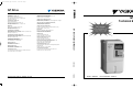
G7 Drive
Technical Manual
Models: CIMR-G7U
Document Number: TM.G7.01
Warnings and Cautions
This Section provides warnings and cautions pertinent to this product, that if not
heeded, may result in personal injury, fatality, or equipment damage. Yaskawa is
not responsible for consequences of ignoring these instructions.
WARNING
YASKAWA manufactures component parts that can be used in a wide variety of industrial applications. The selection and
application of YASKAWA products remain the responsibility of the equipment designer or end user. YASKAWA accepts no
responsibility for the way its products are incorporated into the final system design. Under no circumstances should any
YASKAWA product be incorporated into any product or design as the exclusive or sole safety control. Without exception, all
controls should be designed to detect faults dynamically and fail safely under all circumstances. All products designed to
incorporate a component part manufactured by YASKAWA must be supplied to the end user with appropriate warnings and
instructions as to that part’s safe use and operation. Any warnings provided by YASKAWA must be promptly provided to the
end user. YASKAWA offers an express warranty only as to the quality of its products in conforming to standards and
specifications published in the YASKAWA manual. NO OTHER WARRANTY, EXPRESS OR IMPLIED, IS OFFERED.
YASKAWA assumes no liability for any personal injury, property damage, losses, or claims arising from misapplication of its
products.
WARNING
• Read and understand this manual before installing, operating, or servicing this Drive. All warnings, cautions, and
instructions must be followed. All activity must be performed by qualified personnel. The Drive must be installed according
to this manual and local codes.
• Do not connect or disconnect wiring while the power is on. Do not remove covers or touch circuit boards while the power is
on. Do not remove or insert the digital operator while power is on.
• Before servicing, disconnect all power to the equipment. The internal capacitor remains charged even after the power supply
is turned off. The charge indicator LED will extinguish when the DC bus voltage is below 50Vdc. To prevent electric shock,
wait at least five minutes after all indicators are OFF and measure DC bus voltage level to confirm safe level.
• Do not perform a withstand voltage test on any part of the unit. This equipment uses sensitive devices and may be damaged
by high voltage.
WARNING
• The Drive is suitable for circuits capable of delivering not more than 100,000 RMS symmetrical Amperes, 240Vac
maximum (200-240V Class) and 480Vac maximum (380-480V Class). Install adequate branch circuit short circuit protection per applicable codes. Failure to do so may result in equipment damage and/or personal injury. Refer to Appendix E for
further details.
• Do not connect unapproved LC or RC interference suppression filters, capacitors, or overvoltage protection devices to the
output of the Drive. These devices may generate peak currents that exceed Drive specifications.
i
• To avoid unnecessary fault displays caused by contactors or output switches placed between Drive and motor, auxil-
iary contacts must be properly integrated into the control logic circuit.
• YASKAWA is not responsible for any modification of the product made by the user; doing so will void the warranty.
This product must not be modified.
• Verify that the rated voltage of the Drive matches the voltage of the incoming power supply before applying power.
• To meet CE directives, proper line filters and proper installation are required.
• Some drawings in this manual may be shown with protective covers or shields removed, to describe details. These
must be replaced before operation.
• Observe electrostatic discharge procedures when handling circuit boards to prevent ESD damage.
• The equipment may start unexpectedly upon application of power. Clear all personnel from the Drive, motor, and
machine area before applying power. Secure covers, couplings, shaft keys, and machine loads before energizing the
Drive.
• Please do not connect or operate any equipment with visible damage or missing parts. The operating company is
responsible for any injuries or equipment damage resulting from failure to heed the warnings in this manual.
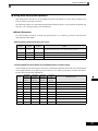
! Intended Use
Drives are intended for installation in electrical systems or machinery.
The Drives are designed and manufactured in accordance with applicable UL and cUL standards, and CE directives.
For use in the European Union, the installation in machinery and systems must conform to the following product standards of the Low Voltage Directive:
EN 50178: 1997-10, Electronic Equipment for Use in Power Installations
EN 60201-1: 1997-12 Machine Safety and Equipping with Electrical Devices
Part 1: General Requirements (IEC 60204-1:1997)
EN 61010: 1997-11 Safety Requirements for Information Technology Equipment
(IEC 950:1991 + A1:1992 + A2:1993 + A3:1995 + A4:1996, modified)
The F7 series Drives comply with the provisions of the Low Voltage Directive 73/23/EEC as amended by 93/68/EEC.
These Drives conform to the following standard: EN 50178: 1997-10.
Your supplier or Yaskawa representative must be contacted when using leakage current circuit breaker in conjunction
with frequency drives.
In certain systems it may be necessary to use additional monitoring and safety devices in compliance with the relevant
safety and accident prevention regulations. The frequency drive hardware must not be modified.
ii
Safety Precautions
! Installation
CAUTION
• Always hold the case when carrying the Drive.
If the Drive is held by the front cover, the main body of the Drive may fall, possibly resulting in injury.
• Attach the Drive to a metal or other noncombustible material.
Fire can result if the Drive is attached to a combustible material.
• Install a cooling fan or other cooling device when installing more than one Drive in the same enclosure so that the temperature of the air entering the Drives is below 45°C.
Overheating can result in fires or other accidents.
iii
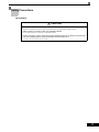
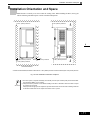
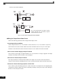
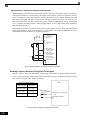
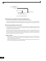
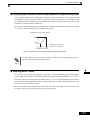
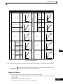
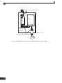
Warning Information and Position
There is warning information on the Drive in the position shown in the following illustration.
Always heed the warnings.
Warning
information
position
Warning
information
position
Illustration shows the CIMR-G7U20P4
Warning Information
iv
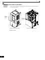
Illustration shows the CIMR-G7U2018
!""
#
!
'
'
$ $
% & ' '
' ( '
v
Registered Trademarks
The following registered trademarks are used in this manual.
• DeviceNet is a registered trademark of the ODVA (Open DeviceNet Vendors Association, Inc.).
• ControlNet is a registered trademark of ControlNet International, Ltd.
• LONworks is a registered trademark of the Echelon.
• MODBUS is a registered trademark of the MODBUS.org.
vi
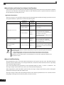
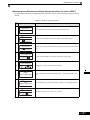
Contents
1
Handling Drives ...................................................................... 1-1
Varispeed G7 Introduction ............................................................................1-2
" Varispeed G7 Models ..................................................................................................... 1-2
Confirmations upon Delivery ........................................................................1-3
" Checks............................................................................................................................ 1-3
" Nameplate Information ................................................................................................... 1-3
" Component Names......................................................................................................... 1-5
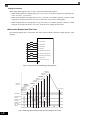
Exterior and Mounting Dimensions...............................................................1-7
" Open Chassis Drives (IP00) ........................................................................................... 1-7
" NEMA Type 1 Drives (IP 20)........................................................................................... 1-8
Checking and Controlling the Installation Site ............................................1-10
" Installation Site ............................................................................................................. 1-10
" Controlling the Ambient Temperature ........................................................................... 1-10
" Protecting the Drive from Foreign Matter...................................................................... 1-10
Installation Orientation and Space .............................................................. 1-11
Removing and Attaching the Terminal Cover .............................................1-12
" Removing the Terminal Cover ...................................................................................... 1-12
" Attaching the Terminal Cover........................................................................................ 1-13
Removing/Attaching the Digital Operator and Front Cover ........................1-14
" Models CIMR-G7U20P4 thru 2015 and 40P4 thru 4015 .............................................. 1-14
" Models CIMR-G7U2018 thru 2110 and 4018 thru 4300 ............................................... 1-17
2
Wiring....................................................................................... 2-1
Connection Diagram.....................................................................................2-2
Terminal Block Configuration........................................................................2-4
Wiring Main Circuit Terminals .......................................................................2-5
"
"
"
"
"
Applicable Wire Sizes and Closed-loop Connectors ...................................................... 2-5
Main Circuit Terminal Functions ................................................................................... 2-13
Main Circuit Configurations........................................................................................... 2-14
Standard Connection Diagrams.................................................................................... 2-15
Wiring the Main Circuits................................................................................................ 2-16
Wiring Control Circuit Terminals .................................................................2-22
" Wire Sizes and Closed-loop Connectors ...................................................................... 2-22
" Control Circuit Terminal Functions ............................................................................... 2-23
" Control Circuit Terminal Connections ........................................................................... 2-29
vii
" Control Circuit Wiring Precautions ............................................................................... 2-30
" Control Circuit Wire Sizes ............................................................................................ 2-30
" Wire Checks ................................................................................................................. 2-30
Installing and Wiring Option Cards............................................................. 2-31
"
"
"
"
"
"
3
Option Card Models and Specifications ....................................................................... 2-31
Installation .................................................................................................................... 2-32
PG Speed Control Card Terminals and Specifications ................................................. 2-33
Wiring ........................................................................................................................... 2-36
Wiring Terminal Blocks................................................................................................. 2-40
Selecting the Number of PG (Encoder) Pulses ............................................................ 2-41
Digital Operator and Modes....................................................3-1
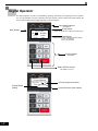
Digital Operator ............................................................................................ 3-2
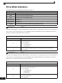
" Digital Operator Display ................................................................................................. 3-2
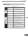
" Digital Operator Keys ..................................................................................................... 3-3
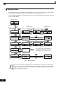
Modes .......................................................................................................... 3-5
"
"
"
"
"
"
"
4
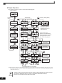
Drive Modes ................................................................................................................... 3-5
Switching Modes ............................................................................................................ 3-6
Drive Mode ..................................................................................................................... 3-7
Quick Programming Mode.............................................................................................. 3-9
Advanced Programming Mode..................................................................................... 3-10
Verify Mode .................................................................................................................. 3-13
Autotuning Mode .......................................................................................................... 3-14
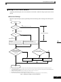
Trial Operation .........................................................................4-1
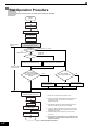
Trial Operation Procedure ............................................................................ 4-2
Trial Operation Procedures .......................................................................... 4-3
"
"
"
"
"
"
"
"
"
"
Setting the Power Supply Voltage Jumper (380-480V Class Drives of 4055 or Higher) 4-3
Power ON....................................................................................................................... 4-3
Checking the Display Status .......................................................................................... 4-4
Basic Settings................................................................................................................. 4-5
Settings for the Control Methods.................................................................................... 4-7
Autotuning ...................................................................................................................... 4-9
Application Settings...................................................................................................... 4-14
No-load Operation ........................................................................................................ 4-14
Loaded Operation......................................................................................................... 4-15
Check and Recording User Parameters....................................................................... 4-16
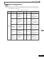
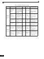
Adjustment Suggestions ............................................................................ 4-17
viii
5
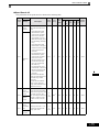
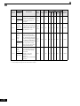
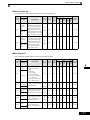
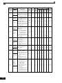
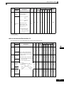
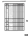
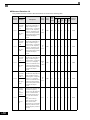
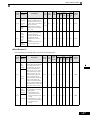
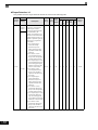
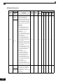
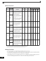
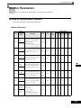
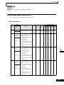
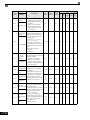
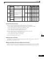
User Parameters ..................................................................... 5-1
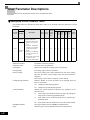
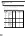
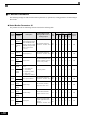
User Parameter Descriptions .......................................................................5-2
" Description of User Parameter Tables ............................................................................ 5-2
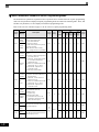
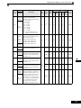
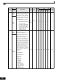
Digital Operation Display Functions and Levels ...........................................5-3
" User Parameters Settable in Quick Programming Mode................................................ 5-4
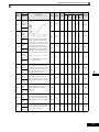
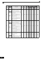
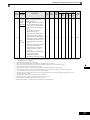
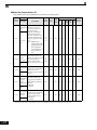
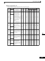
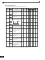
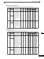
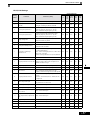
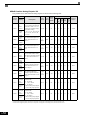
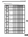
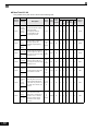
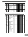
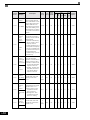
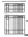
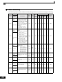
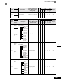
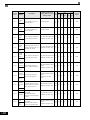
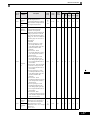
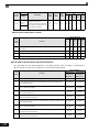
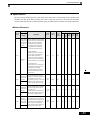
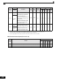
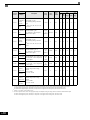
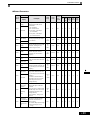
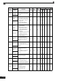
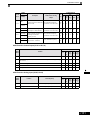
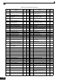
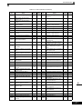
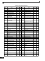
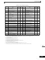
User Parameter Tables...............................................................................5-10
"
"
"
"
"
"
"
"
"
"
"
"
"
"
6
A: Setup Settings .......................................................................................................... 5-10
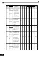
Application Parameters: b............................................................................................. 5-12
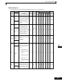
Autotuning Parameters: C ............................................................................................ 5-22
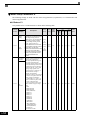
Reference Parameters: d.............................................................................................. 5-28
Motor Setup Parameters: E .......................................................................................... 5-34
Option Parameters: F ................................................................................................... 5-41
Terminal Function Parameters: H.................................................................................5-50
Protection Function Parameters: L ............................................................................... 5-61
N: Special Adjustments................................................................................................. 5-74
Digital Operator Parameters: o ..................................................................................... 5-80
T: Motor Autotuning ...................................................................................................... 5-84
U: Monitor Parameters.................................................................................................. 5-86
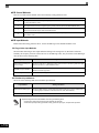
Factory Settings that Change with the Control Method (A1-02) ................................... 5-96
Factory Settings that Change with the Drive Capacity (o2-04)...................................5-102
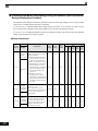
Parameter Settings by Function............................................ 6-1
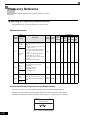
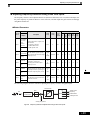
Frequency Reference ...................................................................................6-2
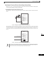
" Selecting the Frequency Reference Source ................................................................... 6-2
" Using Multi-Step Speed Operation ................................................................................. 6-5
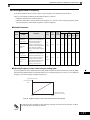
Run Command .............................................................................................6-7
" Selecting the Run Command Source ............................................................................. 6-7
Stopping Methods.........................................................................................6-9
" Selecting the Stopping Method when a Stop Command is Sent..................................... 6-9
" Using the DC Injection Brake........................................................................................ 6-13
" Using an Emergency Stop ............................................................................................ 6-14
Acceleration and Deceleration Characteristics...........................................6-15
" Setting Acceleration and Deceleration Times ............................................................... 6-15
" Accelerating and Decelerating Heavy Loads (Dwell Function)..................................... 6-19
" Preventing the Motor from Stalling During Acceleration (Stall Prevention During
Acceleration Function) .................................................................................................. 6-20
" Preventing Overvoltage During Deceleration (Stall Prevention During Deceleration
Function)....................................................................................................................... 6-22
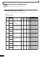
Adjusting Frequency References ...............................................................6-24
" Adjusting Analog Frequency References ..................................................................... 6-24
" Operation Avoiding Resonance (Jump Frequency Function) .......................................6-27
" Adjusting Frequency Reference Using Pulse Train Inputs ........................................... 6-29
ix
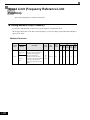
Speed Limit (Frequency Reference Limit Function) ................................... 6-30
" Limiting Maximum Output Frequency........................................................................... 6-30
" Limiting Minimum Frequency ....................................................................................... 6-31
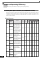
Improved Operating Efficiency ................................................................... 6-32
" Reducing Motor Speed Fluctuation (Slip Compensation Function).............................. 6-32
" Compensating for Insufficient Torque at Startup and Low-speed Operation
(Torque Compensation)................................................................................................ 6-35
" Hunting-prevention Function ........................................................................................ 6-37
" Stabilizing Speed (Speed Feedback Detection Function) ............................................ 6-38
Machine Protection .................................................................................... 6-39
"
"
"
"
"
"
"
"
"
"
Reducing Noise and Leakage Current ......................................................................... 6-39
Limiting Motor Torque (Torque Limit Function) ............................................................ 6-42
Preventing Motor Stalling During Operation ................................................................. 6-44
Changing Stall Prevention Level during Operation Using an Analog Input .................. 6-45
Detecting Motor Torque ................................................................................................ 6-45
Changing Overtorque and Undertorque Detection Levels Using an Analog Input ....... 6-50
Motor Overload Protection ........................................................................................... 6-51
Setting Motor Protection Operation Time ..................................................................... 6-53
Motor Overheating Protection Using PTC Thermistor Inputs ....................................... 6-54
Limiting Motor Rotation Direction ................................................................................. 6-56
Continuing Operation ................................................................................. 6-57
"
"
"
"
Restarting Automatically After Power Is Restored........................................................ 6-57
Speed Search............................................................................................................... 6-59
Continuing Operation at Constant Speed When Frequency Reference Is Lost ........... 6-65
Restarting Operation After Transient Error (Auto Restart Function) ............................ 6-66
Drive Protection.......................................................................................... 6-67
" Performing Overheating Protection on Mounted Braking Resistors............................. 6-67
" Reducing Drive Overheating Pre-Alarm Warning Levels ............................................. 6-68
Input Terminal Functions ............................................................................ 6-69
" Temporarily Switching Operation between Digital Operator and Control Circuit
"
"
"
"
Terminals ...................................................................................................................... 6-69
Blocking Drive Outputs (Baseblock Commands) ......................................................... 6-70
Stopping Acceleration and Deceleration (Acceleration/Deceleration Ramp Hold) ....... 6-71
Raising and Lowering Frequency References Using Contact Signals (UP/DOWN) .... 6-72
Accelerating and Decelerating Constant Frequencies in the Analog References
(+/- Speed) ................................................................................................................... 6-75
Hold Analog Frequency Using User-set Timing ........................................................... 6-76
"
" Switching Operations between a Communications Option Card and Control Circuit
Terminals ...................................................................................................................... 6-76
" Jog Frequency Operation without Forward and Reverse Commands (FJOG/RJOG) . 6-77
" Stopping the Drive by Notifying Programming Device Errors to the Drive
(External Fault Function) .............................................................................................. 6-78
x
Monitor Parameterss ..................................................................................6-79
" Using the Analog Monitor Parameters.......................................................................... 6-79
" Using Pulse Train Monitor Contents ............................................................................. 6-82
Individual Functions....................................................................................6-84
"
"
"
"
"
"
"
"
"
"
Using MODBUS Communications ................................................................................ 6-84
Using the Timer Function.............................................................................................. 6-97
Using PID Control ......................................................................................................... 6-98
Energy-saving.............................................................................................................6-107
Setting Motor Parameters...........................................................................................6-108
Setting the V/f Pattern.................................................................................................6-111
Torque Control............................................................................................................6-120
Speed Control (ASR) Structure...................................................................................6-128
Droop Control Function...............................................................................................6-134
Zero-servo Function....................................................................................................6-135
Digital Operator Functions ........................................................................6-139
"
"
"
"
"
Setting Digital Operator Functions..............................................................................6-139
Copying Parameters ...................................................................................................6-143
Prohibiting Writing Parameters from the Digital Operator...........................................6-148
Setting a Password.....................................................................................................6-149
Displaying User-set Parameters Only.........................................................................6-149
Options .....................................................................................................6-151
"
"
"
"
7
Performing Speed Control with PG.............................................................................6-151
Using Digital Output Cards .........................................................................................6-156
Using an Analog Reference Card ...............................................................................6-159
Using a Digital Reference Card ..................................................................................6-159
Troubleshooting ..................................................................... 7-1
Protective and Diagnostic Functions ............................................................7-2
"
"
"
"
"
Fault Detection................................................................................................................ 7-2
Alarm Detection .............................................................................................................. 7-9
Operation Errors ........................................................................................................... 7-13
Errors During Autotuning ............................................................................................. 7-15
Errors when Using the Digital Operator Copy Function................................................ 7-17
Troubleshooting ..........................................................................................7-18
"
"
"
"
"
"
"
If Parameters Cannot Be Set........................................................................................ 7-18
If the Motor Does Not Operate...................................................................................... 7-19
If the Direction of the Motor Rotation is Reversed ........................................................ 7-21
If the Motor Does Not Put Out Torque or If Acceleration is Slow .................................. 7-21
If the Motor Operates Higher Than the Reference ....................................................... 7-22
If the Slip Compensation Function Has Low Speed Precision...................................... 7-22
If There is Low Speed Control Accuracy at High-speed Rotation in Open-loop Vector
Control Mode ................................................................................................................ 7-22
xi
"
"
"
"
"
"
"
"
8
If Motor Deceleration is Slow........................................................................................ 7-23
If the Motor Overheats.................................................................................................. 7-24
If There is Noise When the Drive is Started or From an AM Radio .............................. 7-24
If the Ground Fault Interrupter Operates When the Drive is Run ................................. 7-25
If There is Mechanical Oscillation................................................................................. 7-25
If the Motor Rotates Even When Drive Output is Stopped ........................................... 7-26
If 0 V is Detected When the Fan is Started, or Fan Stalls............................................. 7-26
If Output Frequency Does Not Rise to Frequency Reference...................................... 7-27
Maintenance and Inspection ..................................................8-1
Maintenance and Inspection ........................................................................ 8-2
"
"
"
"
"
"
9
Outline of Maintenance .................................................................................................. 8-2
Daily Inspection .............................................................................................................. 8-2
Periodic Inspection ......................................................................................................... 8-2
Periodic Maintenance of Parts ....................................................................................... 8-3
Cooling Fan Replacement Outline ................................................................................. 8-4
Removing and Mounting the Control Circuit Terminal Card ........................................... 8-6
Specifications ..........................................................................9-1
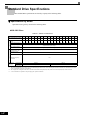
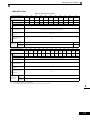
Standard Drive Specifications ...................................................................... 9-2
" Specifications by Model.................................................................................................. 9-2
" Common Specifications.................................................................................................. 9-4
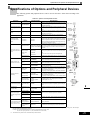
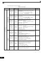
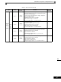
Specifications of Options and Peripheral Devices........................................ 9-5
10
Appendix ................................................................................10-1
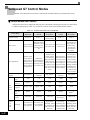
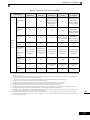
Varispeed G7 Control Modes ..................................................................... 10-2
" Control Modes and Features........................................................................................ 10-2
" Control Modes and Applications................................................................................... 10-6
Drive Application Precautions .................................................................... 10-7
"
"
"
"
Selection....................................................................................................................... 10-7
Installation .................................................................................................................... 10-8
Settings ........................................................................................................................ 10-8
Handling ....................................................................................................................... 10-9
Motor Application Precautions ................................................................. 10-10
" Using the Drive for an Existing Standard Motor ......................................................... 10-10
" Using the Drive for Special Motors ............................................................................. 10-11
" Power Transmission Mechanism (Speed Reducers, Belts, and Chains) ................... 10-11
Conformance to CE Markings .................................................................. 10-12
" CE Markings............................................................................................................... 10-12
" Requirements for Conformance to CE Markings........................................................ 10-12
xii
User Parameters ...................................................................................... 10-19
Handling Drives
This chapter describes the checks required upon receiving or installing an Drive.
Varispeed G7 Introduction ...........................................1-2
Confirmations upon Delivery........................................1-3
Exterior and Mounting Dimensions..............................1-7
Checking and Controlling the Installation Site ...........1-10
Installation Orientation and Space ............................. 1-11
Removing and Attaching the Terminal Cover ............1-12
Removing/Attaching the Digital Operator
and Front Cover .........................................................1-14
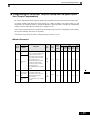
Varispeed G7 Introduction
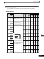
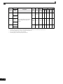
" Varispeed G7 Models
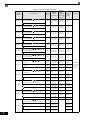
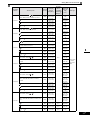
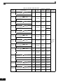
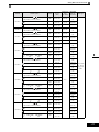
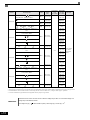
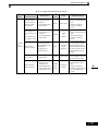
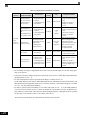
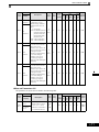
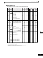
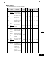
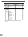
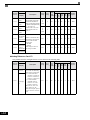
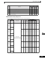
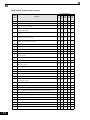
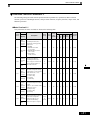
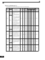
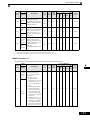
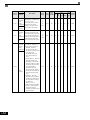
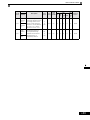
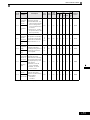
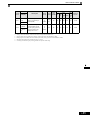
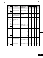
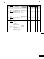
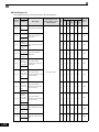
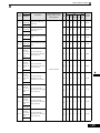
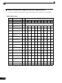
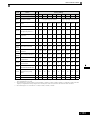
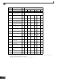
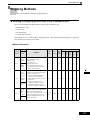
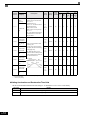
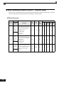
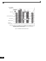
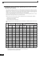
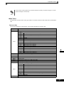
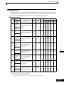
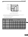
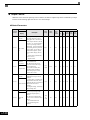
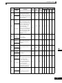
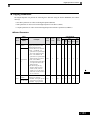
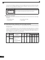
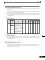
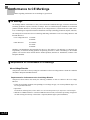
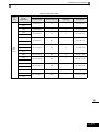
The Varispeed-G7 Series of Drives included two Drives in two voltage classes: 200-240V and 380-480V. Maximum motor
capacities vary from 20P4 to 2110 and 40P4 to 4300 (42 models).
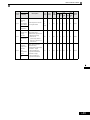
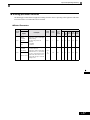
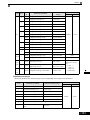
Table 1.1 Varispeed G7 Models
Voltage
Class
200-240V
class
380-480V
class
1-2
Maximum
Motor
Capacity
kW
0.4
0.75
1.5
2.2
3.7
5.5
7.5
11
15
18.5
22
30
37
45
55
75
90
110
0.4
0.75
1.5
2.2
3.7
4.0
5.5
7.5
11
15
18.5
22
30
37
45
55
75
90
110
132
160
185
220
300
Varispeed G7
Output
Capacity
kVA
1.2
2.3
3.0
4.6
6.9
10
13
19
25
30
37
50
61
70
85
110
140
160
1.4
2.6
3.7
4.7
6.9
8.4
11
16
21
26
32
40
50
61
74
98
130
150
180
210
230
280
340
460
Basic Model Number
CIMR-G7U20P4
CIMR-G7U20P7
CIMR-G7U21P5
CIMR-G7U22P2
CIMR-G7U23P7
CIMR-G7U25P5
CIMR-G7U27P5
CIMR-G7U2011
CIMR-G7U2015
CIMR-G7U2018
CIMR-G7U2022
CIMR-G7U2030
CIMR-G7U2037
CIMR-G7U2045
CIMR-G7U2055
CIMR-G7U2075
CIMR-G7U2090
CIMR-G7U2110
CIMR-G7U40P4
CIMR-G7U40P7
CIMR-G7U41P5
CIMR-G7U42P2
CIMR-G7U43P7
CIMR-G7U44P0
CIMR-G7U45P5
CIMR-G7U47P5
CIMR-G7U4011
CIMR-G7U4015
CIMR-G7U4018
CIMR-G7U4022
CIMR-G7U4030
CIMR-G7U4037
CIMR-G7U4045
CIMR-G7U4055
CIMR-G7U4075
CIMR-G7U4090
CIMR-G7U4110
CIMR-G7U4132
CIMR-G7U4160
CIMR-G7U4185
CIMR-G7U4220
CIMR-G7U4300
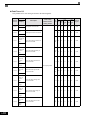
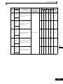
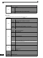
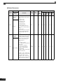
Specifications
(Always specify through the protective structure when ordering.)
Open Chassis
Enclosed Wall-mounted
(IEC IP00)
(IEC IP20, NEMA 1)
CIMR-G7######
CIMR-G7######
20P41#
20P71#
21P51#
22P21#
Remove the top and bottom
23P71#
covers from the Enclosed
25P51#
Wall-mounted model.
27P51#
2011#
20151#
20181#
20220#
20300#
20370#
20450#
20550#
20750#
20900#
21100#
40P41#
40P71#
41P51#
42P21#
43P71#
Remove the top and bottom
covers from the Enclosed
44P01#
Wall-mount model.
45P51#
47P51#
40111#
40151#
40181#
40221#
40301#
40371#
40451#
40550#
40750#
40900#
41100#
41320#
41600#
41850#
42200#
43000#
-
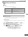
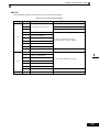
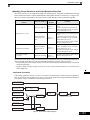
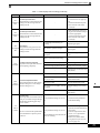
Confirmations upon Delivery
Confirmations upon Delivery
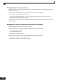
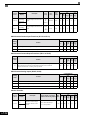
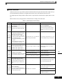
" Checks
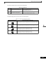
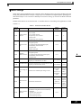
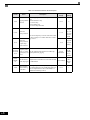
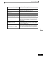
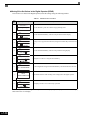
Check the following items as soon as the Drive is delivered.
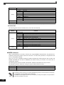
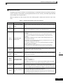
Table 1.2 Checks
Item
Method
Has the correct model of Drive been
delivered?
Check the model number on the nameplate on the side of the Drive.
Is the Drive damaged in any way?
Inspect the entire exterior of the Drive to see if there are any scratches or
other damage resulting from shipping.
Are any screws or other components
loose?
Use a screwdriver or other tools to check for tightness.
If you find any irregularities in the above items, contact the agency from which you purchased the Drive or
your Yaskawa representative immediately.
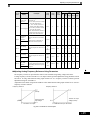
" Nameplate Information
There is a nameplate attached to the side of each Drive. The nameplate shows the model number, specifications, lot number, serial number, and other information on the Drive.
! Example Nameplate
The following nameplate is an example for a standard Drive: 3-phase, 200-240Vac, 0.4kW, IEC IP20 and
NEMA 1 standards.
Drive model
Drive
specifications
G U
Input specifications
Output
specifications
Mass
Lot number
Serial number
Fig 1.1 Nameplate
1-3
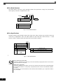
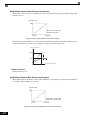
!Drive Model Numbers
The model number of the Drive on the nameplate indicates the specification, voltage class, and maximum
motor capacity of the Drive in alphanumeric codes.
CIMR – G7 U 2 0P4
AC Drive
G7 Family
No.
2
4
Rating
Spec
UL Specification
No.
U
Voltage
3-phase, 208-240Vac
3-phase, 480Vac
Fig 1.2 Drive Model Numbers
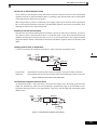
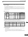
!Drive Specifications
The SPEC number on the nameplate indicates the voltage, Drive rating, enclosure type, and the revision code
of the Drive in alphanumeric codes. The SPEC number for Drives that have custom features, i.e. CASE
software, will have a SPEC number that indicates the custom features installed.
2 0P4 1
No.
2
4
Voltage
AC input, 3-phase, 200-240V
AC input, 3-phase, 380-480V
Enclosure Type
No.
0P4
Max. Motor Capacity
0.4kW
No.
0
Open chassis (IEC IP00)
0P7
to
300
0.75kW
1
NEMA Type 1 (IEC IP20)
to
300kW *
“P” indicates the decimal point
t
Fig 1.3 Drive Specifications
Open Chassis Type (IEC IP00)
Protected so that parts of the human body cannot reach electrically charged parts from the front when the
Drive is mounted in a control panel.
TERMS
NEMA Type 1 (IEC IP20)
The Drive is shielded from the exterior, and can thus be mounted to the interior wall of a standard building
(not necessarily enclosed in a control panel). The protective structure conforms to the standards of NEMA 1
in the USA.
Top protective cover must be installed to conform with IEC IP20 and NEMA 1 Type 1 requirements. Refer to
Fig. 1.4 for details.
1-4
Confirmations upon Delivery
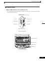
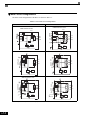
" Component Names
! Models CIMR-G7U20P4 thru 2015 and 40P4 thru 4015
The external appearance and component names of the Drive are shown in Fig 1.4. The Drive with the terminal
cover removed is shown in Fig 1.5.
Top protective cover
[Required for NEMA Type 1 (IEC IP20)]
Mounting hole
Front cover
Digital Operator
Diecast case
Terminal cover
Nameplate
Bottom protective cover
Fig 1.4 Drive Appearance
Control circuit terminals
Main circuit terminals
CAUTION
NPJT31278-1-0
Charge indicator
Ground terminal
Fig 1.5 Terminal Arrangement
1-5
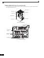
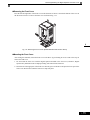
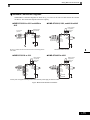
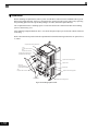
! Models CIMR-G7U2018 thru 2110 and 4018 thru 4300
The external appearance and component names of the Drive are shown in Fig 1.6. The Drive with the terminal
cover removed is shown in Fig 1.7.
Mounting holes
Drive cover
Cooling fan
Front cover
Digital Operator
Nameplate
Terminal cover
Fig 1.6 Drive Appearance
Charge indicator
Control circuit
terminals
Main circuit
terminals
Ground terminal
Terminal Arrangement(18.5kW or More)
Fig 1.7 Terminal Arrangement
1-6
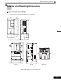
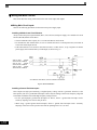
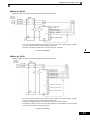
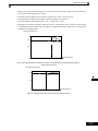
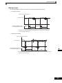
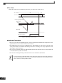
Exterior and Mounting Dimensions
Exterior and Mounting Dimensions
" Open Chassis Drives (IP00)
Exterior diagrams of the Open Chassis Drives are shown below.
W1
H
H1
4-d
W
H2
t1
D1
3
D
H1
H
Models CIMR-G7U20P4 thru 2015 and 40P4 thru 4015
CHARGE
H2
t1
(5)∗
W
Front View
(5)∗
D1
D
Side View
Bottom View
Models CIMR-G7U2018 thru 2110 and 4018 thru 4160
1-7
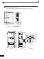
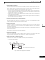
" NEMA Type 1 Drives (IP 20)
Exterior diagrams of the Enclosed Wall-mounted Drives (NEMA1 Type 1) are shown below.
H
H0
4-d
H1
W1
4
H3
W
H2
t1
D1
3
D
Models CIMR-G7U20P4 thru 2015 and 40P4 thru 4015
H1
H0
H
4-d
CHARGE
+1
+3
W1
W
Front View
(5)*
t1
max.10
(5)*
H3
H2
-
(5)
D
D1
Side View
Models CIMR-G7U2018 thru 2075 and 4018 thru 4160
1-8
Bottom View
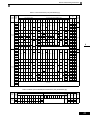
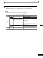
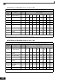
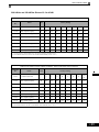
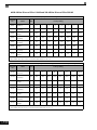
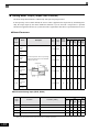
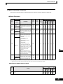
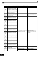
Exterior and Mounting Dimensions
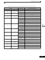
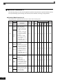
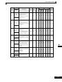
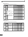
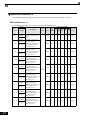
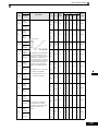
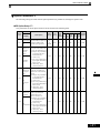
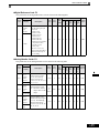
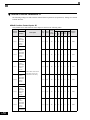
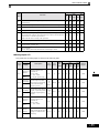
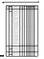
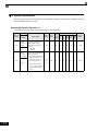
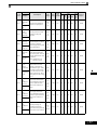
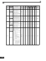
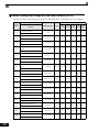
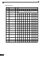
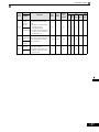
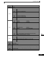
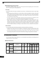
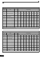
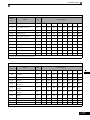
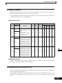
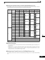
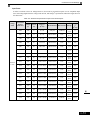
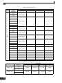
Table 1.3 Drive Dimensions (mm) and Masses (kg)
Heat Generation
(W)
Dimensions (mm)
Voltage
Class
Model
CIMRG7U
Open Chassis (IP00)
W
H
D
W1
H1
Enclosed Wall-mounted (NEMA Type 1)
H2
D1
t1
Approx
Mass
W
H
D
W1
H0
H1
H2
H3
D1
t1
Approx
Mass
Mount- External Internal Total
Heat
ing
Holes*
20P4
20P7
21P5
157
140
280
22P2
266
300
197
186
285
240
350
207
216
335
2018
250
400
195
385
2022
275
450
220
435
375
600
250
575
450
725
350
325
700
500
850
360
370
820
575
885
380
445
855
2011
2015
2030
2037
2045
2055
2075
2090
2110
40P4
41P5
260
300
330
140
280
8
78
200
7
2.3
100
100
3.2
39
266
7
300
350
7
186
300
285
207
216
350
335
195
400
385
220
450
435
165
250
600
575
209
535
24
279
613
380
809
453
1027
348
325
725
700
504
1243
361
370
850
820
63
86
298
328
8
0
7.5
47P5
4011
4015
4018
380-480V
(3-phase)
4022
15
4075
4090
4110
4132
4160
2.3
100
100
3.2
130
393
4.5
140
280
4.5
39
126
280
266
240
275
300
350
450
197
207
258
186
216
220
285
8
65.5
335
7
78
435
7.5
100
10
2.3
26
240
279
325
550
283
260
535
105
37
329
300
350
535
635
197
207
258
285
216
220
260
300
350
450
550
285
8
725
348
325
700
12.5
500
850
358
370
820
15
575
916
378
445
855
45.8
3.2
130
90
91
109
4.5
140
127
165
175
105
186
6
187
87
274
7
263
112
375
357
136
493
473
174
647
24
599
241
840
27
679
257
936
62
878
362
1240
1080
434
1514
1291
510
1801
95
1474
607
2081
114
M12 2009
823
2832
1660
871
2531
11
68
94
M6
M10
10
39
49
21
44
65
33
46
79
41
49
90
77
63
140
100
66
166
132
80
212
197
107
304
246
116
362
311
135
446
354
174
528
516
210
726
633
246
879
737
285
1022
929
340
1269
1239
488
1727
1554
597
2151
M5
6
78
7.5
100
10
2.3
29
M6
85
535
39
105
715
450
47
136
4.5
65.5
335
435
85
58
64
3.5
59
186
57
53
5
7
177
200
42
83
0
200
36
43
Natural
Fan
2389 1194 3583
157
4045
4055
135
78
21
122
---
4030
4037
30
302
44P0
45P5
0
M5
4
65.5
12.5
150
5
5
0
197
260
3
59
254
380
3.5
59
266
21
87
4.5
280
240
108
140
126
11
57
130
15
280
39
177
6
7.5
177
43P7
140
4
65.5
12.5
126
157
5
157
40P7
42P2
7
3
59
200
27P5
200-240V
(3-phase)
126
177
23P7
25P5
39
Cooling
Method
165
453
1027
348
325
725
700
12.5
302
504
1243
358
370
850
820
15
393
579
1324
378
445
916
855
45.8
408
40
3.2
130
4.5
140
98
99
M10
127
1928
762
2690
137
2299
928
3227
175
185
M12
Natural
Fan
2612 1105 3717
3614 1501 5115
4185
4220
See Table 1.4
4300
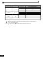
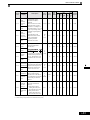
* Same for Open Chassis and Enclosed Wall-mounted Drives
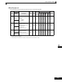
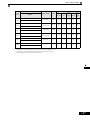
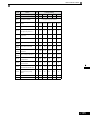
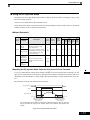
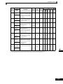
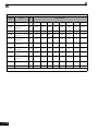
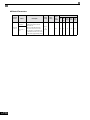
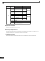
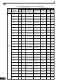
Table 1.4 480Vac (185 to 300 kW) Drive Dimensions (mm) and Masses (kg)
Dimensions (mm)
Model
Voltage
CIMRClass
G7U
380480V
(3-phase)
4185
4220
4300
Open Chassis (IP00)
W
H
D
W1 W2 W3
H1
H2
Heat Generation (W)
Enclosed Wall-mounted (NEMA Type1)
D1
t1
710 1305 413 540 240 270 1270
15
125.5 4.5
916 1475 413 730 365 365 1440
15
125.5 4.5
Approx
W H D W1 W2 W3
Mass
H1 H2 D1
t1
Approx
Mass
Mount- External Internal
ing
Holes*
Total
Heat
4436
1995
6431
5329
2205
7534
6749
2941
9690
260
280
415
---
M12
Cooling
Method
Fan
1-9
Checking and Controlling the Installation Site
Install the Drive in the installation site described below and maintain optimum conditions.
" Installation Site
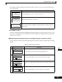
Install the Drive to a non-combustible surface under the following conditions in UL Pollution Degree 2 environments. This excludes wet locations where pollution may become conductive due to moisture, and locations
containing conductive foreign matter
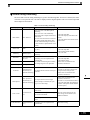
Table 1.5 Installation Site
Type
Ambient Operating Temperature
Humidity
NEMA Type 1
14° F-to- 104°F (-10-to- + 40 °C)
95% RH or less (no condensation)
Open chassis
14° F-to- 113°F (-10-to- + 45 °C)
95% RH or less (no condensation)
Protective covers are attached to the top and bottom of the Drive. It is recommended to remove the protective
covers before operating a NEMA Type 1 Drive (Models CIMR-G7U2015/4015 and smaller) in a panel to
obtain the 113° (45°C) ambient operating temperature.
Observe the following precautions when installing the Drive. Make sure to install:
• In a clean location which is free from oil mist and dust.
• In an environment where metal shavings, oil, water, or other foreign materials do not get into the Drive.
• In a location free from radioactive materials and combustible materials (e.g. wood).
• In a location free from harmful gases and liquids.
• In a location free from excessive vibration.
• In a location free from chlorides
• In a location away from direct sunlight.
" Controlling the Ambient Temperature
To enhance the reliability of operation, the Drive should be installed in an environment free from extreme temperature variation. If the Drive is installed in an enclosure, use a cooling fan or air conditioner to maintain the
internal air temperature below 113°F (45°C).
" Protecting the Drive from Foreign Matter
During Drive installation and project construction, it is possible to have foreign matter such as metal shavings
or wire clippings fall inside the Drive. To prevent foreign matter from falling into the Drive, place a temporary
cover over the Drive.
Always remove the temporary cover from the Drive before start-up. Otherwise, ventilation will be reduced,
causing the Drive to overheat.
1-10
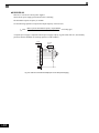
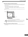
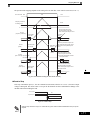
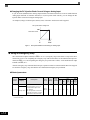
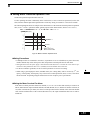
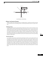
Installation Orientation and Space
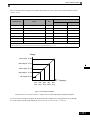
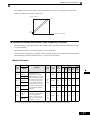
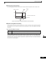
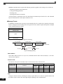
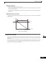
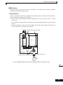
Installation Orientation and Space
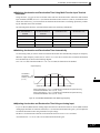
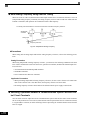
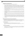
Install the Drive vertically so as not to reduce the cooling effect. When installing the Drive, always provide the following installation space to allow normal heat dissipation.
1.97in * (50mm) minimum
4.72in (120mm) minimum
Air
1.2in
(30.5mm) minimum
1.97in (50mm) minimum
1.2in
(30.5mm) minimum
4.75in (120mm) minimum
Horizontal Clearance
Air
Vertical Clearance
* For Drive model G7U4300, this clearance dimension is 11.81in (300mm) minimum. All other models require 1.97in (50mm) minimum.
Fig 1.8 Drive Installation Orientation and Space
IMPORTANT
1. The same space is required horizontally and vertically for both Open Chassis (IP00) and Enclosed Wallmounted (IP20, NEMA 1 Type 1) Drives.
2. Always remove the protection covers before installing a 200-240 or 380-480 V Class Drive with an output
of 15 kW or less in a panel.
Always provide enough space for suspension eye bolts and the main circuit lines when installing a 200-240
or 380-480 V Class Drive with an output of 18.5 kW or more in a panel.
1-11
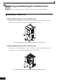
Removing and Attaching the Terminal Cover
Remove the terminal cover to wire cables to the control circuit and main circuit terminals.
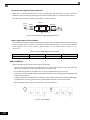
" Removing the Terminal Cover
! Models CIMR-G7U20P4 thru 2015 and 40P4 thru 4015
Loosen the screws at the bottom of the terminal cover, press in on the sides of the terminal cover in the
directions of arrows 1, and then lift up on the terminal in the direction of arrow 2.
1
2
1
Fig 1.9 Removing the Terminal Cover (Model CIMR-G7U23P7 Shown Above)
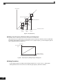
! Models CIMR-G7U2018 thru 2110 and 4018 thru 4300
Loosen the screws on the left and right at the top of the terminal cover, pull out the terminal cover in the
direction of arrow 1 and then lift up on the terminal in the direction of arrow 2.
1
2
Fig 1.10 Removing the Terminal Cover (Model CIMR-G7U2018 Shown Above)
1-12
Removing and Attaching the Terminal Cover
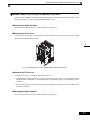
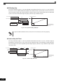
" Attaching the Terminal Cover
After wiring the terminal block, attach the terminal cover by reversing the removal procedure.
For Models CIMR-G7U2015/4015 and smaller, insert the tab on the top of the terminal cover into the groove on the
Drive, and press in on the bottom of the terminal cover until it clicks into place.
For Drives CIMR-G7U2018/4018 and larger, insert the tab on the top of the terminal cover into the groove on the
Drive, and secure the terminal cover by lifting it up toward the top of the Drive.
1-13
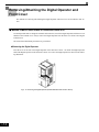
Removing/Attaching the Digital Operator and
Front Cover
The methods of removing and attaching the Digital Operator and Front Cover are described in this section.
" Models CIMR-G7U20P4 thru 2015 and 40P4 thru 4015
To attach optional cards or change the terminal card connector, remove the Digital Operator and front cover in
addition to the terminal cover. Always remove the Digital Operator from the front cover before removing the
terminal cover.
The removal and attachment procedures are given below.
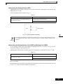
!Removing the Digital Operator
Press the lever on the side of the Digital Operator in the direction of arrow 1 to unlock the Digital Operator
and lift the Digital Operator in the direction of arrow 2 to remove the Digital Operator as shown in the following illustration.
2
1
Fig 1.11 Removing the Digital Operator (Model CIMR-G7U43P7 Shown Above)
1-14
Removing/Attaching the Digital Operator and Front Cover
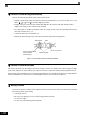
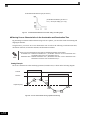
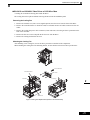
!Removing the Front Cover
Press the left and right sides of the front cover in the directions of arrows 1 and lift the bottom of the cover in
the direction of arrow 2 to remove the front cover as shown in Fig. 1.12.
1
1
2
Fig 1.12 Removing the Front Cover (Model CIMR-G7U43P7 Shown Above)
!Mounting the Front Cover
After wiring the terminals, mount the front cover to the Drive by performing in reverse order to the steps to
remove the front cover.
1. Do not mount the front cover with the Digital Operator attached to the front cover; otherwise, Digital
Operator may malfunction due to improper mating with control board connector.
2. Insert the tab of the upper part of the front cover into the groove of the Drive and press the lower part of the
front cover onto the Drive until the front cover snaps into place.
1-15
!Mounting the Digital Operator
After attaching the front cover, mount the Digital Operator onto theDrive using the following procedure.
1. Hook the Digital Operator at A (two locations) on the left side of the opening on the front cover in the
direction of arrow 1 as shown in the following illustration.
2. Press the Digital Operator in the direction of arrow 2 until it snaps in place at B (two locations).
A
1
B
2
Fig 1.13 Mounting the Digital Operator
IMPORTANT
1-16
1. Do not remove or attach the Digital Operator or mount or remove the front cover using methods other than
those described above, otherwise the Drive may break or malfunction due to imperfect contact.
2. Never attach the front cover to the Drive with the Digital Operator attached to the front cover. Imperfect
contact can result.
Always attach the front cover to the Drive by itself first, and then attach the Digital Operator to the front
cover.
Removing/Attaching the Digital Operator and Front Cover
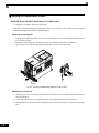
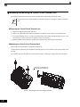
" Models CIMR-G7U2018 thru 2110 and 4018 thru 4300
For Drive models CIMR-G7U2018 thru 2110 and 4018 thru 4300, remove the terminal cover and then use the
following procedures to remove the Digital Operator and main cover.
!Removing the Digital Operator
Use the same procedure as for Drives with an output of 18.5 kW or less.
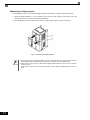
!Removing the Front Cover
Loosen all screws on the front cover. Lift up at the location labelled 1 at the top of the control circuit terminal
card and move in the direction of arrow 2.
2
1
Fig 1.14 Removing the Front Cover (Model CIMR-G7U2018 Shown Above)
! Attaching the Front Cover
Attach the front cover by reversing the procedure to remove it.
1. Confirm that the Digital Operator is not mounted on the front cover. If the cover is attached while the
Digital Operator is mounted to it, the Digital Operator may malfunction due to improper mating with its
connector.
2. Insert the tab on the top of the front cover into the slot on the Drive and press in on the cover until it clicks
into place on the Drive.
!Attaching the Digital Operator
Use the same procedure as for Drives with an output of 18.5 kW or less.
1-17
1-18
Wiring
This chapter describes wiring terminals, main circuit terminal connections, main circuit terminal wiring specifications, control circuit terminals, and control circuit wiring specifications.
Connection Diagram ....................................................2-2
Terminal Block Configuration .......................................2-4
Wiring Main Circuit Terminals ......................................2-5
Wiring Control Circuit Terminals ................................2-22
Installing and Wiring Option Cards ............................2-31
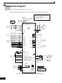
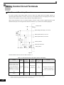
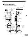
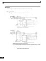
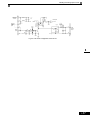
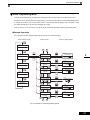
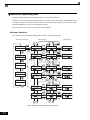
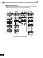
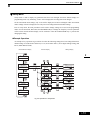
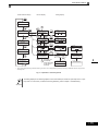
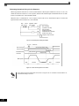
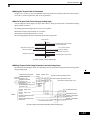
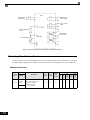
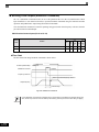
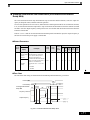
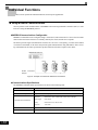
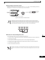
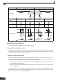
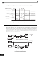
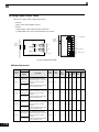
Connection Diagram
The connection diagram of the Drive is shown in Fig 2.1.
When using the Digital Operator, the motor can be operated by wiring only the main circuits.
12 Pulse Input Terminals R1/L11, S1/L21, T1/L31 are standard
on CIMR-G7U2018 - 2110 and CIMR-G7U4018 - 4300.
DC Link Choke
Standard:
CIMR-G7U2018 to 2110
CIMR-G7U4018 to 4300
U
Branch circuit
protection supplied
by others.
X
External Braking Terminal + 3 is standard on CIMR-G7U2018
- 2110 and CIMR-G7U4018 - 4300.
Braking Terminals B1, B2 are standard on CIMR-G7U20P4 2015 and CIMR-G7U40P4- 4015.
Remove if adding
external DC link
choke
Shorting Bar Standard:
CIMR-G7U20P4 to 2015
CIMR-G7U40P4 to 4015
+ 2
+ 1
+ 3
B1
-
B2
Motor
MCCB
3-Phase
Power Supply
50/60Hz
L1
R/L1
U/T1
L2
S/L2
V/T2
L3
T/L3
W/T3
G7
R/L11
Remove jumpers if
using 12 pulse input
T1
T2
T3
M
S/L21
T/L31
MA
Foward Run/Stop
Digital Inputs
24VDC, 8mA
Reverse Run/Stop
MC
S2
External Fault
(H2-01)
S4 (H1-02)
Multi-Step Reference1
Multi-Step Reference2
Jog Reference
M2
S5 (H1-03)
(H2-02)
M4
Multi-Step Reference4
Accel / Decel Time 1
(H2-03)
S9 (H1-07)
M6
S10 (H1-08)
Frequency Agree 1
P3
S11 (H1-09)
Fast-Stop N.O.
Multi-function
Digital Outputs 2-4
250VAC, 30VDC, 1A
Zero Speed
M5
S8 (H1-06)
Multi-Step Reference3
During Run
M3
S6 (H1-04)
S7 (H1-05)
Baseblock
Digital Output 1
Fault Contact
250VAC, 30VDC, 1A
M1
S3 (H1-01)
Fault Reset
Multi-function
Digital Inputs
24VDC, 8 mA
MB
S1
(H2-04)
C3
Inverter Ready
Multi-function
Digital Outputs 5-6
48VDC, 50mA
S12 (H1-10)
P4
SN
(H2-05)
SC
C4
Minor Fault - Alarm
SP +24VDC
E(G)
+V +15VDC +/-10%, 20mA
2k Ω
E(G)
-V -15VDC +/-10%, 20mA
A1 0 to +/-10VDC, 20 k Ω *
2k Ω
(H4-01) FM
External
Frequency
Reference
A2 4 to 20mA, 250 Ω * (S1-2 ON)
[0 to +/-10VDC, 20k Ω **] (S1-2 OFF)
Multi-function Analog Input 1 (H3-09)
(H4-04) AM
A3 0 to +/-10VDC, 20k Ω *
Multi-function Analog Input 2 (H3-05)
RP 0 to 32kHz, 5 to 12VDC, 3kΩ ***
Multi-function Pulse Input (H6-01)
Modbus RTU
Communications
RS-485/422
19.2 Kbps
RS+
Terminating
Resistor
110 Ω
+
-
Output Frequency
Output Current
Output Frequency
S1-1
Jumper CN15
CH1
CH2
See Page 2-25 for details.
V
DIP Switch S1
S1-1
S1-2
SIG
-
(H6-06) MP
AC
R+
AC
+
OFF
ON
* +/-11 Bit Resolution, 0.2% Accuracy
** 10 Bit Resolution, 0.2% Accuracy
*** +/-1% Accuracy
Fig 2.1 Connection Diagram (Model CIMR-G7U2018 Shown Above)
2-2
Multi-function
Analog Output 1 - 2
0 to +/-10VDC, 2mA
4-20mA, 500 Ω
+/-9 Bit Resolution
+/- 8% Accuracy
Multi-function
Pulse Output
0 to 32kHz
9VDC @ 3k Ω
+/-1% Accuracy
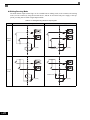
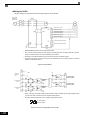
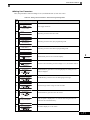
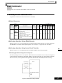
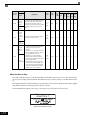
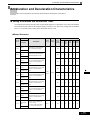
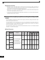
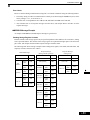
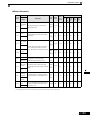
Connection Diagram
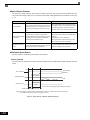
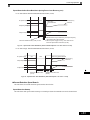
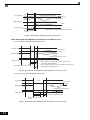
1. Control circuit terminals are arranged as shown below.
IMPORTANT
E(G)
S11 S12
S−
S+
R−
R+
C4
P4
C3
P3
S9 S10
RP
AC
MP
A3
−V
AC
+V
A2
SN
SP
A1
SC
IG
AM
AC
FM
S8
S7
S6
S5
S1
S3
S4
S2
M5
M6
MA
MB
M3
M4
M1
MC
M2
E(G)
2. The output current capacity of the +V terminal is 20 mA.
3. Disable the stall prevention during deceleration (set parameter L3-04 to 0) when using a Braking Resistor
Unit. If this user parameter is not changed to disable stall prevention, the system may not stop during
deceleration.
4. Main circuit terminals are indicated with double circles and control circuit terminals are indicated with single
circles.
5. The wiring for a motor with a cooling fan is not required for self-cooling motors.
6. PG circuit wiring (i.e., wiring to the PG-X2 Card) is not required for open-loop vector control.
7. Sequence input signals S1 to S12 are labeled for sequence connections (0 V common and sinking mode)
for no-voltage contacts or NPN transistors. These are the default settings.
For PNP transistor sequence connections (+24V common and sourcing mode) or to provide a 24-V external power supply, refer toTable 2.13.
8. The master speed frequency reference can set to input either a voltage (terminal A1) or current (terminal
A2) by changing the setting of parameter H3-13. The default setting is for a voltage reference input.
9. The multi-function analog output is a dedicated meter output for an analog frequency meter, ammeter, voltmeter, wattmeter, etc. Do not use this output for feedback control or for any other control purpose.
10.DC reactors to improve the input power factor built into 200-240 V Class Drives for 18.5 to 110 kW and
380-480 V Class Drives for 18.5 to 300 kW. A DC reactor is thus an option only for Drives for 15 kW or less.
11.Set parameter L8-01 to 1 when using a breaking resistor (ERF). When using a Braking Resistor Unit, a
shutoff sequence for the power supply must be made using a thermal relay trip.
2-3
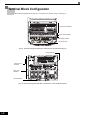
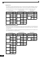
Terminal Block Configuration
The terminal arrangement for 200-240 V Class Drives are shown in Fig 2.2 and Fig 2.3.
Control circuit terminals
Main circuit terminals
CAUTION
NPJT31278-1-0
Charge indicator
Ground terminal
Fig 2.2 Terminal Arrangement (200-240 V Class Drive for 0.4 kW Shown Above)
Charge indicator
Control circuit
terminals
Main circuit
terminals
Ground terminal
Terminal Arrangement(18.5kW or More)
Fig 2.3 Terminal Arrangement (200-240 V Class Drive for 18.5 kW Shown Above)
2-4
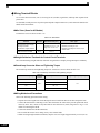
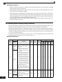
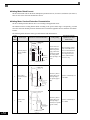
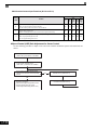
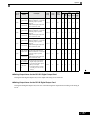
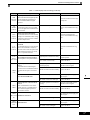
Wiring Main Circuit Terminals
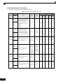
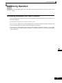
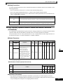
Wiring Main Circuit Terminals
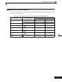
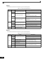
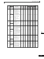
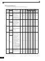
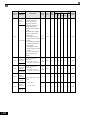
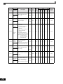
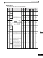
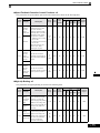
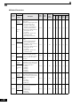
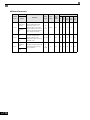
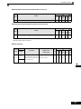
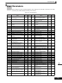
" Applicable Wire Sizes and Closed-loop Connectors
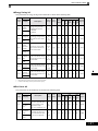
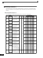
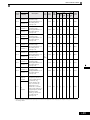
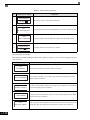
Select the appropriate wires and crimp terminals from Table 2.1 to Table 2.3. Refer to instruction manual
TOE-C726-2 for wire sizes for Braking Resistor Units and Braking Units.
2-5
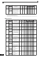
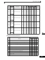
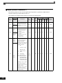
Table 2.1 200-240 V Class Wire Sizes
Drive Model
CIMR-#
Terminal
Screws
Terminal Symbol
Clamping
Torque
lb•in(N•m)
Terminal
Recommended
Block
Wire Size
Acceptable
AWG
Wire Range
(mm2)
Wire Type
AWG(mm2)
R/L1, S/L2, T/L3,
U/T1, V/T2, W/T3
,
G7U20P4
R/L1, S/L2, T/L3,
U/T1, V/T2, W/T3
,
G7U20P7
R/L1, S/L2, T/L3,
U/T1, V/T2, W/T3
,
G7U21P5
R/L1, S/L2, T/L3,
U/T1, V/T2, W/T3
,
G7U22P2
R/L1, S/L2, T/L3,
U/T1, V/T2, W/T3
,
G7U23P7
R/L1, S/L2, T/L3,
U/T1, V/T2, W/T3
,
G7U25P5
R/L1, S/L2, T/L3,
U/T1, V/T2, W/T3
,
G7U27P5
R/L1, S/L2, T/L3,
V/T2, W/T3
,
G7U2011
1,
1,
1,
1,
1,
1,
1,
2, B1, B2,
,
1,
2, U/T1,
2, U/T1,
3
2-6
/ 2
10.6 to 13.2
(1.2 to 1.5)
18 to 10
(0.82 to 5.5)
14
(2)
M4
10.6 to 13.2
(1.2 to 1.5)
18 to 10
(0.82 to 5.5)
14
(2)
M4
10.6 to 13.2
(1.2 to 1.5)
18 to 10
(0.82 to 5.5)
12
(3.5)
M4
10.6 to 13.2
(1.2 to 1.5)
18 to 10
(0.82 to 5.5)
10
(5.5)
M5
20.4 to 22.1
(2.3 to 2.5)
10 to 6
(5.5 to 14)
8
(8)
M5
20.4 to 22.1
(2.3 to 2.5)
10 to 6
(5.5 to 14)
6
(14)
M6
35.2 to 44
(4.0 to 5.0)
8 to 1
(8 to 50)
4
(22)
2, B1, B2,
3
r/ 1,
M4
2, B1, B2,
R/L1, S/L2, T/L3,
,
1 U/T1,
V/T2, W/T3, R1/L11, S1/L21, T1/L31
G7U2030
14
(2)
2, B1, B2,
B1, B2
3
18 to 10
(0.82 to 5.5)
2, B1, B2,
R/L1, S/L2, T/L3,
,
1 U/T1,
V/T2, W/T3, R1/L11, S1/L21, T1/L31
G7U2022
10.6 to 13.2
(1.2 to 1.5)
2, B1, B2,
R/L1, S/L2, T/L3,
,
1, U/T1, V/T2,
W/T3, R1/L11, S1/L21, T1/L31
G7U2018
M4
2, B1, B2,
B1, B2
R/L1, S/L2, T/L3,
V/T2, W/T3
G7U2015
1,
M5
20.4 to 22.1
(2.3 to 2.5)
12 to 6
(3.5 to 14)
Application
Dependent
M6
35.2 to 44
(4.0 to 5.0)
*3
*3
M8
79.2 to 88
(9.0 to 10.0)
8 to 1
(8 to 50)
3
(30)
M5
20.4 to 22.1
(2.3 to 2.5)
12 to 6
(3.5 to 14)
Application
Dependent
M6
35.2 to 44
(4.0 to 5.0)
*3
*3
M8
79.2 to 88
(9.0 to 10.0)
8 to 1/0
(8 to 60)
3
(30)
M6
35.2 to 44
(4.0 to 5.0)
8 to 22
(8 to 4)
Application
Dependent
M8
79.2 to 88
(9.0 to 10.0)
*3
*3
M8
79.2 to 88
(9.0 to 10.0)
8 to 1/0
(50 to 60)
1
(50)
M6
35.2 to 44
(4.0 to 5.0)
8 to 22
(8 to 4)
Application
Dependent
M8
79.2 to 88
(9.0 to 10.0)
*3
*3
M10
155 to 198
(17.6 to 22.5)
2/0
(60)
M8
78 to 95
(8.8 to 10.8)
Application
Dependent
M10
155 to 198
(17.6 to 22.5)
M4
11.4 to 12.3
(1.3 to 1.4)
N/A
2
(30)
16
(1.25)
Power cables,
e.g., 600 V
vinyl power
cables
Wiring Main Circuit Terminals
Drive Model
CIMR-#
Terminal Symbol
Terminal
Screws
Clamping
Torque
lb•in(N•m)
Terminal
Recommended
Block
Wire Size
Acceptable
AWG
Wire Range
(mm2)
Wire Type
AWG(mm2)
R/L1, S/L2, T/L3,
,
1 U/T1,
V/T2, W/T3, R1/L11, S1/L21, T1/L31
G7U2037
3
r/ 1,
/ 2
R/L1, S/L2, T/L3,
, 1, U/T1, V/T2,
W/T3, R1/L11, S1/L21, T1/L31
G7U2045
3
r/ 1,
,
/ 2
1
R/L1, S/L2, T/L3, U/T1, V/T2, W/T3,
R1/L11, S1/L21, T1/L31
G7U2055
3
r/ 1,
/ 2
R/L1, S/L2, T/L3,
,
1
U/T1, V/T2, W/T3, R1/L11, S1/L21,
T1/L31
G7U2075
3
r/ 1,
/ 2
R/L1, S/L2, T/L3,
G7U2090
,
1
U/T1, V/T2, W/T3, R1/L11, S1/L21,
T1/L31
3
r/ 1,
/ 2
R/L1, S/L2, T/L3,
G7U2110
,
1
U/T1, V/T2, W/T3, R1/L11, S1/L21, T1/
L31
3
r/ 1,
/ 2
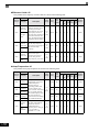
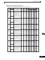
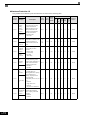
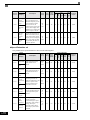
* The wire thickness is set for copper wires at 75°C
M10
155 to 198
(17.6 to 22.5)
3/0
(80)
M8
78 to 95
(8.8 to 10.8)
Application
Dependent
M10
155 to 198
(17.6 to 22.5)
1
(38)
M4
11.4 to 12.3
(1.3 to 1.4)
16
(1.25)
M10
155 to 198
(17.6 to 22.5)
1/0 × 2P
(50 × 2P)
M8
78 to 95
(8.8 to 10.8)
Application
Dependent
M10
155 to 198
(17.6 to 22.5)
1/0
(50)
M4
11.4 to 12.3
(1.3 to 1.4)
16
(1.25)
M12
276 to 345
(31.4 to 39.2)
3/0 × 2P
(80 × 2P)
M10
155 to 198
(17.6 to 22.5)
3/0 × 2P
(80 × 2P)
M8
78 to 95
(8.8 to 10.8)
Application
Dependent
M12
155 to 198
(17.6 to 22.5)
2/0
(80)
M4
11.4 to 12.3
(1.3 to 1.4)
16
(1.25)
M12
276 to 345
(31.4 to 39.2)
M12
276 to 345
(31.4 to 39.2)
4/0 × 2P
(100 × 2P)
M8
78 to 95
(8.8 to 10.8)
Application
Dependent
M12
276 to 345
(31.4 to 39.2)
2/0 × 2P
(60 × 2P)
M4
11.4 to 12.3
(1.3 to 1.4)
16
(1.25)
M12
276 to 345
(31.4 to 39.2)
350 × 2P, or
1/0 × 4P
(200 × 2P, or
50 × 4P)
M12
276 to 345
(31.4 to 39.2)
300 × 2P, or
1/0 × 4P
(150 × 2P, or
50 × 4P)
M8
78 to 95
(8.8 to 10.8)
Application
Dependent
M12
276 to 345
(31.4 to 39.2)
300 × 2P
(150 × 2P)
M4
11.4 to 12.3
(1.3 to 1.4)
16
(1.25)
M12
276 to 345
(31.4 to 39.2)
350 × 2P, or
1/0 × 4P
(200 × 2P, or
50 × 4P)
M12
276 to 345
(31.4 to 39.2)
300 × 2P, or
1/0 × 4P
(150 × 2P, or
50 × 4P)
M8
78 to 95
(8.8 to 10.8)
N/A
Application
Dependent
M12
276 to 345
(31.4 to 39.2)
N/A
300 × 2P
(150 × 2P)
M4
11.4 to 12.3
(1.3 to 1.4)
N/A
16
(1.25)
N/A
250 × 2P
(150 × 2P)
Power cables,
e.g., 600 V
vinyl power
cables
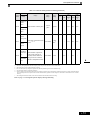
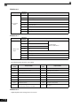
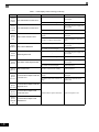
2-7
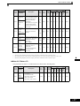
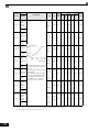
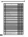
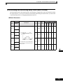
Table 2.2 380-480 V Class Wire Sizes
Drive Model
CIMR-#
Terminal Symbol
R/L1, S/L2, T/L3,
U/T1, V/T2, W/T3
,
G7U40P4
R/L1, S/L2, T/L3,
U/T1, V/T2, W/T3
,
G7U40P7
R/L1, S/L2, T/L3,
U/T1, V/T2, W/T3
,
G7U41P5
,
G7U42P2
R/L1, S/L2, T/L3,
U/T1, V/T2, W/T3
R/L1, S/L2, T/L3,
U/T1, V/T2, W/T3
,
G7U43P7
,
G7U44P0
R/L1, S/L2, T/L3,
U/T1, V/T2, W/T3
R/L1, S/L2, T/L3,
U/T1, V/T2, W/T3
,
G7U45P5
R/L1, S/L2, T/L3,
U/T1, V/T2, W/T3
,
G7U47P5
R/L1, S/L2, T/L3,
U/T1, V/T2, W/T3
,
1,
1,
1,
1,
1,
1,
1,
1,
1,
Terminal
Screws
Tightening
Torque
(N•m)
Possible Wire
Sizes
mm2 (AWG)
Recommended
Wire Size
mm2 (AWG)
M4
10.6 to 13.2
(1.2 to 1.5)
18 to 10
(0.82 to 5.5)
14
(2)
M4
10.6 to 13.2
(1.2 to 1.5)
18 to 10
(0.82 to 5.5)
14
(2)
M4
10.6 to 13.2
(1.2 to 1.5)
18 to 10
(0.82 to 5.5)
14
(2)
M4
10.6 to 13.2
(1.2 to 1.5)
18 to 10
(0.82 to 5.5)
M4
10.6 to 13.2
(1.2 to 1.5)
18 to 10
(0.82 to 5.5)
12
(3.5)
M4
10.6 to 13.2
(1.2 to 1.5)
18 to 10
(0.82 to 5.5)
12
(3.5)
M4
10.6 to 13.2
(1.2 to 1.5)
10 to 6
(5.5 to 14)
10
(5.5)
M5
20.4 to 22.1
(2.3 to 2.5)
10 to 6
(5.5 to 14)
8
(8)
M5
20.4 to 22.1
(2.3 to 2.5)
10 to 6
(5.5 to 14)
8
(8)
M5
(M6)
20.4 to 22.1
(2.3 to 2.5)
35.2 to 44
(4.0 to 5.0)
10 to 6
(5.5 to 14)
10
(5.5)
M5
35.2 to 44
(4.0 to 5.0)
10 to 6
(5.5 to 14)
8
(8)
M5
20.4 to 22.1
(2.3 to 2.5)
10 to 6
(5.5 to 14)
8
(8)
M5
(M6)
35.2 to 44
(4.0 to 5.0)
10 to 6
(5.5 to 14)
8
(8)
M6
35.2 to 44
(4.0 to 5.0)
12 to 3
(3.5 to 30)
6
(14)
M8
79.2 to 88
(9.0 to 10.0)
*3
*3
M6
35.2 to 44
(4.0 to 5.0)
12 to 3
(3.5 to 30)
4
(22)
M8
79.2 to 88
(9.0 to 10.0)
*3
*3
2, B1, B2,
2, B1, B2,
2, B1, B2,
2, B1, B2,
2, B1, B2,
G7U4015
G7U4018
G7U4022
2-8
,
1,
12
(3.5)
14
(2)
2, B1, B2,
2, B1, B2,
2, B1, B2,
2, B1, B2,
G7U4011
R/L1, S/L2, T/L3,
V/T2, W/T3
Wire Type
2, U/T1,
B1, B2
R/L1, S/L2, T/L3,
,
1,
3, U/T1,
V/T2, W/T3, R1/L11, S1/L21, T1/L31
R/L1, S/L2, T/L3,
,
1,
3, U/T1,
V/T2, W/T3, R1/L11, S1/L21, T1/L31
Power cables,
e.g., 600 V
vinyl power
cables
Wiring Main Circuit Terminals
Terminal
Screws
Tightening
Torque
(N•m)
Possible Wire
Sizes
mm2 (AWG)
Recommended
Wire Size
mm2 (AWG)
M8
79.2 to 88
(9.0 to 10.0)
8 to 1/0
(8 to 60)
2
(38)
M6
35.2 to 44
(4.0 to 5.0)
(8 to 4)
8 to 22
Application
Dependent
M8
79.2 to 88
(9.0 to 10.0)
*3
*3
R/L1, S/L2, T/L3,
,
1, U/T1, V/T2,
W/T3, R1/L11, S1/L21, T1/L31
M8
79.2 to 88
(9.0 to 10.0)
2 to 1/0
(30 to 60)
2
(38)
R/L1, S/L2, T/L3,
,
1, U/T1, V/T2,
W/T3, R1/L11, S1/L21, T1/L31
M8
79.2 to 88
(9.0 to 10.0)
8 to 1/0
(8 to 60)
1
(50)
M6
35.2 to 44
(4.0 to 5.0)
8 to 4
(8 to 22)
Application
Dependent
M8
79.2 to 88
(9.0 to 10.0)
*3
*3
M10
154.8 to 197.5
(17.6 to 22.5)
1/0
(50)
M8
78 to 95
(8.8 to 10.8)
Application
Dependent
M10
154.8 to 197.5
(17.6 to 22.5)
2
(38)
M4
11.4 to 12.3
(1.3 to 1.4)
16
(1.25)
M10
154.8 to 197.5
(17.6 to 22.5)
4/0
(100)
M8
78 to 95
(8.8 to 10.8)
Application
Dependent
M10
154.8 to 197.5
(17.6 to 22.5)
1
(50)
M4
11.4 to 12.3
(1.3 to 1.4)
16
(1.25)
M10
154.8 to 197.5
(17.6 to 22.5)
1/0 × 2P
(50 × 2P)
M8
78 to 95
(8.8 to 10.8)
Drive Model
CIMR-#
Terminal Symbol
R/L1, S/L2, T/L3,
,
1, U/T1, V/T2,
W/T3, R1/L11, S1/L21, T1/L31
G7U4030
G7U4037
G7U4045
3
3
R/L1, S/L2, T/L3,
,
1, U/T1, V/T2,
W/T3, R1/L11, S1/L21, T1/L31
G7U4055
3
r/ 1, 200/ 2200,
400/ 2400
R/L1, S/L2, T/L3,
,
1, U/T1, V/T2,
W/T3, R1/L11, S1/L21, T1/L31
G7U4075
3
r/ 1,
200/ 2200,
400/ 2400
R/L1, S/L2, T/L3,
,
1, U/T1, V/T2,
W/T3, R1/L11, S1/L21, T1/L33
G7U4090
3
r/ 1,
200/ 2200,
400/ 2400
R/L1, S/L2, T/L3,
,
1, U/T1, V/T2,
W/T3, R1/L11, S1/L21, T1/L33
G7U4110
3
r/ 1,
200/ 2200,
400/ 2400
R/L1, S/L2, T/L3,
,
1, U/T1, V/T2,
W/T3, R1/L11, S1/L21, T1/L31
G7U4132
3
r/ 1,
200/ 2200,
400/ 2400
N/A
Wire Type
Power cables,
e.g., 600 V
vinyl power
cables
Application
Dependent
M12
154.8 to 197.5
(17.6 to 22.5)
2/0
(60)
M4
11.4 to 12.3
(1.3 to 1.4)
16
(1.25)
M10
154.8 to 197.5
(17.6 to 22.5)
3/0 × 2P
(80 × 2P)
M8
78 to 95
(8.8 to 10.8)
Application
Dependent
M12
154.8 to 197.5
(17.6 to 22.5)
4/0
(100)
M4
11.4 to 12.3
(1.3 to 1.4)
16
(1.25)
M12
276 to 345
(31.4 to 39.2)
3/0 × 2P
(80 × 2P)
M8
78 to 95
(8.8 to 10.8)
Application
Dependent
M12
276 to 345
(31.4 to 39.2)
1/0 × 2P
(50 × 2P)
M4
11.4 to 12.3
(1.3 to 1.4)
16
(1.25)
2-9
Drive Model
CIMR-#
Terminal Symbol
R/L1, S/L2, T/L3,
,
1, U/T1, V/T2,
W/T3, R1/L11, S1/L21, T1/L31
3
G7U4160
r/ 1,
200/ 2200,
400/ 2400
Possible Wire
Sizes
mm2 (AWG)
Recommended
Wire Size
mm2 (AWG)
Terminal
Screws
Tightening
Torque
(N•m)
M12
276 to 345
(31.4 to 39.2)
4/0 × 2P
(100 × 2P)
M8
78 to 95
(8.8 to 10.8)
Application
Dependent
M12
276 to 345
(31.4 to 39.2)
1/0 × 2P
(50 × 2P)
M4
11.4 to 12.3
(1.3 to 1.4)
16
(1.25)
R/L1, S/L2, T/L3, R1/L11, S1/L21, T1/
L31
250 x 2P
(125 x 2P)
U/T1, V/T2, W/T3
250 x 2P
(125 x 2P)
,
M16
1
G7U4185
694 to 867
(78.4 to 98.0)
Wire Type
600 x 2P
(325 x 2P)
Application
Dependent
3
3/0 x 2P
(80 x 2P)
r/ 1,
200/ 2200,
400/ 2400
M4
R/L1, S/L2, T/L3, R1/L11, S1/L21, T1/
L31
N/A
350 x 2P
(185 x 2P)
300 x 2P
(150 x 2P)
U/T1, V/T2, W/T3
,
16
(1.25)
11.4 to 12.3
(1.3 to 1.4)
M16
1
G7U4220
694 to 867
(78.4 to 98.0)
Power cables,
e.g., 600 V
vinyl power
cables
250 x 4P
(125 x 4P)
Application
Dependent
3
4/0 x 2P
(100 x 2P)
r/ 1,
200/ 2200,
400/ 2400
M4
11.4 to 12.3
(1.3 to 1.4)
16
(1.25)
R/L1, S/L2, T/L3, R1/L11, S1/L21, T1/
L31
600 x 2P
(325 x 2P)
U/T1, V/T2, W/T3
500 x 2P
(300 x 2P)
,
M16
1
G7U4300
694 to 867
(78.4 to 98.0)
400 x 4P
(200 x 4P)
Application
Dependent
3
250 x 2P
(125 x 2P)
r/ 1,
200/ 2200,
400/ 2400
M4
11.4 to 12.3
(1.3 to 1.4)
16
(1.25)
* The wire thickness is set for copper wires at 75°C.
*1 Wire size range provided for Drives using insulated screw-type terminal blocks with a single conductor. Refer to applicable codes for proper wire type and size.
*2 Recommended wire sizes are based on the Drive current ratings and NEC Article 310 Table 310.16, 75 Degree Celsius copper or equivalent.
*3 Uses non-insulated screw-type terminals. Refer to applicable codes for proper wire type and size.
Determine the wire size for the main circuit so that line voltage drop is within 2% of the rated voltage. Line
IMPORTANT
voltage drop is calculated as follows:
Line voltage drop (V) =
2-10
3 x wire resistance (Ω/km) x wire length (m) x current (A) x 10-3
Wiring Main Circuit Terminals
Table 2.3 Closed-loop Connector Sizes (JIS C2805) (200-240 V Class and 380-480 V Class)
Wire Size *
AWG
mm2
20
0.5
18
16
14
12 / 10
8
6
4
3/2
1 / 1/0
2/0
3/0
Terminal Screw
Ring Tongue (R-Type) Closed-Loop Connectors (Lugs)
JST Corporation Part Numbers **
M3.5
1.25 - 3.7
M4
1.25 - 4
M3.5
1.25 - 3.7
M4
1.25 - 4
M3.5
1.25 - 3.7
M4
1.25 - 4
M3.5
2 - 3.7
M4
2-4
M5
2-5
M6
2-6
M8
2-8
M4
5.5 - 4
M5
5.5 - 5
M6
5.5 - 6
M8
5.5 - 8
M5
8-5
M6
8-6
M8
8-8
M5
14 - 5
M6
14 - 6
M8
14 - 8
M5
22 - 5
M6
22 - 6
M8
22 - 8
M6
38 - 6
M8
38 - 8
M8
60 - 8
M10
60 - 10
M8
70 - 8
M10
70 - 10
M10
80 - 10
M16
80 - 16
0.75
1.25
2
3.5 / 5.5
8
14
22
30 / 38
50 / 60
70
80
2-11
Wire Size *
4/0
250 / 300MCM
100
125 / 150
400MCM
200
650MCM
325
Terminal Screw
Ring Tongue (R-Type) Closed-Loop Connectors (Lugs)
JST Corporation Part Numbers **
M10
100 - 10
M12
100 - 12
M16
100 - 16
M10
150 - 10
M12
150 - 12
M16
150 - 16
M12
200 - 12
M12 x 2
325 - 12
M16
325 - 16
* Wire sizes are based on 75 degrees Celsius copper wire.
** Equivalent connector can be used.
Determine the wire size for the main circuit so that line voltage drop is within 2% of the rated voltage. Line
voltage drop is calculated as follows:
IMPORTANT
2-12
Line voltage drop (V) =
3 x wire resistance (W/km) x wire length (m) x current (A) x 10-3
Wiring Main Circuit Terminals
" Main Circuit Terminal Functions
Main circuit terminal functions are summarized according to terminal symbols in Table 2.4. Wire the terminals
correctly for the desired purposes.
Table 2.4 Main Circuit Terminal Functions (200-240 V Class and 380-480 V Class)
Purpose
Terminal Symbol
Model: CIMR-G7U#
208-240 Vac
480 Vac
R/L1, S/L2, T/L3
20P4 to 2110
40P4 to 4300
R1/L11, S1/L21, T1/L31
2018 to 2110
4018 to 4300
U/T1, V/T2, W/T3
20P4 to 2110
40P4 to 4300
20P4 to 2110
40P4 to 4300
20P4 to 27P5
40P4 to 4015
20P4 to 2015
40P4 to 4015
2018 to 2110
4018 to 4300
20P4 to 2110
40P4 to 4300
Main circuit power input
Drive outputs
DC power input
1,
Braking Resistor Unit connecB1, B2
tion
DC link choke connection
1,
Braking Transistor Unit connection
3,
Ground
2
2-13
" Main Circuit Configurations
The main circuit configurations of the Drive are shown in Table 2.5.
Table 2.5 Drive Main Circuit Configurations
208-240 Vac
480 Vac
CIMR-G7U40P4 to 4015
CIMR-G7U20P4 to 2015
B1 B2
B1 B2
+1
+1
+2
+2
U/T1
R/L1
S/L2
T/L3
V/T2
W/T3
U/T1
R/L1
S/L2
T/L3
V/T2
W/T3
−
−
Power
supply
Control
circuits
Power
supply
CIMR-G7U2018, 2022
CIMR-G7U4018 to 4045
+3
+3
+1
+1
R/L1
S/L2
T/L3
R1/L11
S1/L21
T1/L31
U/T1
V/T2
W/T3
−
Power
supply
R/L1
V/T2
W/T3
Power
supply
Control
circuits
Control
circuits
CIMR-G7U4055 to 4300
+3
+3
+1
+1
R/L1
S/L2
T/L3
R1/L11
S1/L21
T1/L31
−
U/T1
V/T2
W/T3
r/ l 1
R/L1
S/L2
T/L3
R1/L11
S1/L21
T1/L31
−
U/T1
V/T2
W/T3
r/ l 1
Power
supply
Control
circuits
Note Consult your Yaskawa representative before using 12-phase rectification.
2-14
U/T1
S/L2
T/L3
R1/L11
S1/L21
T1/L31
−
CIMR-G7U2030 to 2110
/l2
Control
circuits
200/ l 2200
400/ l 2400
Power
supply
Control
circuits
Wiring Main Circuit Terminals
" Standard Connection Diagrams
Standard Drive connection diagrams are shown in Fig 2.4. These are the same for both 208-240 Vac and 480
Vac Drives. The connections depend on the Drive capacity.
!CIMR-G7U20P4 to 2015 and 40P4 to
4015
− + 1 + 2 B1 B2
R/L1
U/T1
S/L2
V/T2
T/L3
W/T3
Braking Unit
(optional)
IM
3-phase 200-240
Vac(380-480 Vac)
Be sure to remove the short-circuit bar before connecting the DC
link choke.
!CIMR-G7U2030 to 2110
3-phase
200-240Vac
Braking Resistor
Unit (optional)
Braking Resistor
Unit (optional)
DC link choke
(optional)
3-phase 200-240Vac
(380-480 Vac)
!CIMR-G7U2018, 2022, and 4018 to 4045
+1
R/L1
S/L2
T/L3
R1/L11
S1/L21
T1/L31
r/l1
/l2
+1
R/L1
S/L2
T/L3
R1/L11
S1/L21
T1/L31
+3 −
U/T1
V/T2
W/T3
IM
The DC link choke is built in.
!CIMR-G7U4055 to 4300
Braking Resistor
Unit (optional)
Braking Resistor
Unit (optional)
Braking Unit
(optional)
Braking Unit
(optional)
+3 −
U/T1
V/T2
W/T3
IM
+1
+3 −
R/L1
U/T1
S/L2
V/T2
T/L3
W/T3
3-phase 380-480 Vac R1/L11
S1/L21
T1/L31
r/l1
200/l2200
400/l2400
IM
Control power is supplied internally from the main circuit DC power supply for all Drive models.
Fig 2.4 Main Circuit Terminal Connections
2-15
" Wiring the Main Circuits
This section describes wiring connections for the main circuit inputs and outputs.
!Wiring Main Circuit Inputs
Observe the following precautions for the main circuit power supply input.
Installing a Molded-case Circuit Breaker
Always connect the power input terminals (R/L1, S/L2, and T/L3) and power supply via a molded-case circuit
breaker (MCCB) suitable for the Drive.
• Choose an MCCB with a capacity of 1.5 to 2 times the Drive's rated current.
• For the MCCB's time characteristics, be sure to consider the Drive's overload protection (one minute at
150% of the rated output current).
• If the same MCCB is to be used for more than one Drive, or other devices, set up a sequence so that the
power supply will be turned OFF by a fault output, as shown in Fig 2.5.
Drive
Power
supply
R/L1
20P4 to 2030:
3-phase,
200 to 240 Vac, 50/60 Hz
2037 to 2110:
3-phase,
200 to 230 Vac, 50/60 Hz
40P4 to 4300:
3-phase,
380 to 460 Vac, 50/60 Hz
S/L2
T/L3
Fault output
(NC)
* For 380-480 V class Drives, connect a 460/230 V transformer.
Fig 2.5 MCCB Installation
Installing a Ground Fault Interrupter
Drive outputs use high-speed switching, so high-frequency leakage current is generated. Therefore, at the
Drive primary side, use a ground fault interrupter to detect only the leakage current in the frequency range that
is hazardous to humans and exclude high-frequency leakage current.
• For the special-purpose ground fault interrupter for Drives, choose a ground fault interrupter with a
sensitivity amperage of at least 30 mA per Drive.
• When using a general ground fault interrupter, choose a ground fault interrupter with a sensitivity
amperage of 200 mA or more per Drive and with an operating time of 0.1 s or more.
2-16
Wiring Main Circuit Terminals
Installing a Magnetic Contactor
If the power supply for the main circuit is to be shut off during a sequence, a magnetic contactor can be used.
When a magnetic contactor is installed on the primary side of the main circuit to forcibly stop the Drive,
however, the regenerative braking does not work and the Drive will coast to a stop.
• The Drive can be started and stopped by opening and closing the magnetic contactor on the primary side.
Frequently opening and closing the magnetic contactor, however, may cause the Drive to break down. Start
and stop the Drive at most once every 30 minutes.
• When the Drive is operated with the Digital Operator, automatic operation cannot be performed after
recovery from a power interruption.
• If the Braking Resistor Unit is used, program the sequence so that the magnetic contactor is turned OFF by
the contact of the Unit's thermal overload relay.
Connecting Input Power Supply to the Terminal Block
Input power supply can be connected to any terminal R/L1, S/L2, or T/L3 on the terminal block; the phase
sequence of input power supply is irrelevant to the phase sequence.
Installing an AC Reactor
If the Drive is connected to a large-capacity power transformer (600 kVa or more) or the phase advancing
capacitor is switched, an excessive peak current may flow through the input power circuit, causing the
converter unit to break down.
To prevent this, install an optional AC Reactor on the input side of the Drive or a DC link choke to the DC link
choke connection terminals.
This also improves the power factor on the power supply side.
Installing a Surge Absorber
Always use a surge absorber or diode for inductive loads near the Drive. These inductive loads include
magnetic contactors, electromagnetic relays, solenoid valves, solenoids, and magnetic brakes.
Installing a Noise Filter on Power Supply Side
Install a noise filter to eliminate noise transmitted between the power line and the Drive.
• Correct Noise Filter Installation
Power
supply
MCCB
Noise
filter
MCCB
Drive
IM
Other
controllers
Use a special-purpose noise filter for Drives.
Fig 2.6 Correct Power supply Noise Filter Installation
2-17
• Incorrect Noise Filter Installation
Power
supply
MCCB
Drive
MCCB
Power
supply
Generalpurpose
noise filter
IM
Other
controllers
MCCB
Generalpurpose
noise filter
Drive
IM
MCCB
Other
controllers
Do not use general-purpose noise filters. Generalpurpose noise filter can not effectively suppress
noise generated from the Drive.
Fig 2.7 Incorrect Power supply Noise Filter Installation
!Wiring the Output Side of Main Circuit
Observe the following precautions when wiring the main output circuits.
Connecting the Drive and Motor
Connect output terminals U/T1, V/T2, and W/T3 to motor lead wires U/T1, V/T2, and W/T3, respectively.
Check that the motor rotates forward with the forward run command. Switch over any two of the output
terminals to each other and reconnect if the motor rotates in reverse with the forward run command.
Never Connect a Power Supply to Output Terminals
Never connect a power supply to output terminals U/T1, V/T2, and W/T3. If voltage is applied to the output
terminals, the internal circuits of the Drive will be damaged.
Never Short or Ground Output Terminals
If the output terminals are touched with bare hands or the output wires come into contact with the Drive
casing, an electric shock or grounding will occur. This is extremely hazardous. Do not short the output wires.
Do Not Use a Phase Advancing Capacitor or Noise Filter
Never connect a phase advancing capacitor or LC/RC noise filter to an output circuit. The high-frequency
components of the Drive output may result in overheating or damage to these part or may result in damage to
the Drive or cause other parts to burn.
2-18
Wiring Main Circuit Terminals
Do Not Use an Electromagnetic Switch
Never connect an electromagnetic switch (MC) between the Drive and motor and turn it ON or OFF during
operation. If the MC is turned ON while the Drive is operating, a large inrush current will be created and the
overcurrent protection in the Drive will operate.
When using an MC to switch to a commercial power supply, stop the Drive and motor before operating the
MC. Use the speed search function if the MC is operated during operation. If measures for momentary power
interrupts are required, use a delayed release MC.
Installing a Thermal Overload Relay
This Drive has an electronic thermal protection function to protect the motor from overheating. If, however,
more than one motor is operated with one Drive or a multi-pole motor is used, always install a thermal relay
(THR) between the Drive and the motor and set L1-01 to 0 (no motor protection). The sequence should be
designed so that the contacts of the thermal overload relay turn OFF the magnetic contactor on the main circuit
inputs.
Installing a Noise Filter on Output Side
Connect a noise filter to the output side of the Drive to reduce radio noise and inductive noise.
Power
supply
MCCB
Drive
Noise
filter
IM
Radio noise
Signal line
Inductive
noise
AM radio
Controller
Inductive Noise:
Electromagnetic induction generates noise on the signal line, causing the controller to malfunction.
Radio Noise:
Electromagnetic waves from the Drive and cables cause the broadcasting radio receiver to make noise.
Fig 2.8 Installing a Noise Filter on the Output Side
Countermeasures Against Inductive Noise
As described previously, a noise filter can be used to prevent inductive noise from being generated on the
output side. Alternatively, cables can be routed through a grounded metal pipe to prevent inductive noise.
Keeping the metal pipe at least 30 cm (approximately 1 foot) away from the signal line considerably reduces
inductive noise.
Power
supply
Metal pipe
MCCB
Drive
IM
Signal line
30 cm min.
(1 ft.)
Controller
Fig 2.9 Countermeasures Against Inductive Noise
2-19
Countermeasures Against Radio Interference
Radio noise is generated from the Drive as well as from the input and output lines. To reduce radio noise,
install noise filters on both input and output sides, and also install the Drive in a totally enclosed steel box.
The cable between the Drive and the motor should be as short as possible.
Power
supply
Steel box
Metal pipe
MCCB
Noise
filter
Drive
Noise
filter
IM
Fig 2.10 Countermeasures Against Radio Interference
Cable Length between Drive and Motor
If the cable between the Drive and the motor is long, the high-frequency leakage current will increase, causing
the Drive output current to increase as well. This may affect peripheral devices. To prevent this, adjust the
carrier frequency (set in C6-01, C6-02) as shown in Table 2.6. (For details, refer to Chapter 3 User
Parameters.)
Table 2.6 Cable Length between Drive and Motor
Cable length
50 m max. (164 ft)
100 m max. (328 ft)
More than 100 m (> 328 ft)
Carrier frequency
15 kHz max.
10 kHz max.
5 kHz max.
!Ground Wiring
Observe the following precautions when wiring the ground line.
• Always use the ground terminal of the 200-240 V Drive with a ground resistance of less than 100 Ω and
that of the 380-480 V Drive with a ground resistance of less than 10 Ω.
• Do not share the ground wire with other devices, such as welding machines or power tools.
• Always use a ground wire that complies with technical standards on electrical equipment and minimize the
length of the ground wire.
Leakage current flows through the Drive. Therefore, if the distance between the ground electrode and the
ground terminal is too long, potential on the ground terminal of the Drive will become unstable.
• When using more than one Drive, be careful not to loop the ground wire.
OK
NO
Fig 2.11 Ground Wiring
2-20
Wiring Main Circuit Terminals
!Connecting the Braking Resistor (ERF)
A Braking Resistor that mounts to the Drive can be used with 200-240 V and 380-480 V Class Drives with
outputs from 0.4 to 3.7 kW.
Connect the braking resistor as shown in Fig 2.12.
Table 2.7
L8-01 (Protect selection for internal DB resistor)
1 (Enables overheat protection)
L3-04 (Stall prevention selection during deceleration)
(Select either one of them.)
0 (Disables stall prevention function)
3 (Enables stall prevention function with braking resistor)
Drive
Braking resistor
Fig 2.12 Connecting the Braking Resistor
The braking resistor connection terminals are B1 and B2. Do not connect to any other terminals. Connecting
to any terminals other than B1 or B2 can cause the resistor to overheat, resulting in damage to the
equipment.
IMPORTANT
!Connecting the Braking Resistor Unit (LKEB) and Braking Unit (CDBR)
Use the following settings when using a Braking Resistor Unit. Refer to User Parameters on page 10-19 for
connection methods for a Braking Resistor Unit.
A Braking Resistor that mounts to the Drive can also be used with Drives with outputs from 0.4 to 3.7 kW.
Table 2.8
L8-01 (Protect selection for internal DB resistor)
0 (Disables overheat protection)
L3-04 (Stall prevention selection during deceleration)
(Select either one of them.)
0 (Disables stall prevention function)
3 (Enables stall prevention function with braking resistor)
L8-01 is used when a braking resistor without thermal overload relay trip contacts (ERF type mounted to
Drive) is connected.
The Braking Resistor Unit cannot be used and the deceleration time cannot be shortened by the Drive if L3-04
is set to 1 (i.e., if stall prevention is enabled for deceleration).
2-21
Wiring Control Circuit Terminals
" Wire Sizes and Closed-loop Connectors
For remote operation using analog signals, keep the control line length between the Digital Operator or
operation signals and the Drive to 50 m (164 ft) or less, and separate the lines from high-power lines (main
circuits or relay sequence circuits) to reduce induction from peripheral devices.
When setting frequencies from an external frequency reference (and not from a Digital Operator), used
shielded twisted-pair wires and ground the shield to terminal E (G), as shown in the following diagram.
Shield terminal
Speed setting power supply, +15 V 20 mA
2 kΩ
Master speed reference, -10 to 10 V
2 kΩ
Master speed reference, 4 to 20 mA
2 kΩ
2 kΩ
Auxiliary reference
Pulse input, 32 kHz max.
Analog common
Fig 2.13
Terminal numbers and wire sizes are shown in Table 2.9.
Table 2.9 Terminal Numbers and Wire Sizes (Same for all Models)
Terminals
Terminal
Screws
Tightening
Torque
lb-in (N•m)
Possible Wire
Sizes
AWG (mm2)
Recommended
Wire Size AWG
(mm2)
FM, AC, AM, M3, M4,
SC, A1, A2, A3, +V, -V,
S1, S2, S3, S4, S5, S6,
S7, S8, MA, MB, MC,
M1, M2, P3, C3, P4, C4,
MP, RP, R+, R-, S9, S10,
S11, S12, S+, S-, IG, SN,
SP
Phoenix
type*3
4.2 to 5.3
(0.5 to 0.6)
Stranded wire:
26 to 16
(0.14 to 1.5)
18
(0.75)
E (G)
M3.5
7.0 to 8.8
(0.8 to 1.0)
20 to 14
(0.5 to 2)
12
(1.25)
Wire Type
•Shielded, twisted-pair wire*1
•Shielded, polyethylenecovered, vinyl sheath cable*2
* 1. Use shielded twisted-pair cables to input an external frequency reference.
* 2. Yaskawa recommends using straight solderless terminals on digital inputs to simplify wiring and improve reliability.
* 3. Yaskawa recommends using a thin-slot screwdriver with a 3.5 mm blade width.
2-22
Wiring Control Circuit Terminals
" Control Circuit Terminal Functions
The functions of the control circuit terminals are shown in Table 2.10. Use the appropriate terminals for the correct
purposes.
Table 2.10 Control Circuit Terminals
Type
Digital
input
signals
No.
Signal Name
Function
Signal Level
S1
Forward run/stop command
Forward run when CLOSED; stopped when OPEN.
S2
Reverse run/stop command
Reverse run when CLOSED; stopped when OPEN.
S3
Multi-function input 1*1
Factory setting: External fault when
CLOSED.
S4
Multi-function input 2*1
Factory setting: Fault reset when CLOSED.
S5
Multi-function input 3*1
Factory setting: Multi-speed speed
reference 1 effective when CLOSED.
S6
Multi-function input 4*1
Factory setting: Multi-speed speed
reference 2 effective when CLOSED.
S7
Multi-function input 5*1
Factory setting: Jog frequency selected when
CLOSED.
S8
Multi-function input 6*1
Factory setting: External baseblock when
CLOSED.
S9
Multi-function input 7*1
Factory setting: Multi-speed speed
reference 3 effective when CLOSED.
S10
Multi-function input 8*1
Factory setting: Multi-speed speed
reference 4 effective when CLOSED.
S11
Multi-function input 9*1
Factory setting: Accel/decel time selected
when CLOSED.
S12
Multi-function input 10*1
Factory setting: Emergency stop
(NO contact) when CLOSED.
SC
Sequence input common
Multifunction
digital
inputs.
Functions
set by
H1-01 to
H1-10
24 Vdc, 8 mA
Photocoupler
isolation
-
2-23
Table 2.10 Control Circuit Terminals (Continued)
Type
Analog
input
signals
No.
Signal Name
Function
Signal Level
+V
+15 V power output
+15 V power supply for analog input
or transmitters
+15 V
(Max. current: 20
mA)
-V
-15 V power output
-15 V power supply for analog input
or transmitters
-15 V
(Max. current: 20
mA)
A1
Master speed frequency
reference
-10 to +10 V/-100 to 100%
0 to +10 V/100%
-10 to +10 V, 0 to
+10 V (Input impedance: 20 kΩ)
A2
4 to 20 mA/100%, -10 to +10 V/-100 to
+100%, 0 to +10 V/100%
Multifunction
analog
input 3.
Function
set by
H3-05
4 to 20 mA (Input
impedance: 250 Ω)
4 to 20 mA (Input
impedance: 250 Ω)
Multi-function analog input
AC
Analog reference common
0V
-
E(G)
Shield wire, optional ground
line connection point
-
-
Multi-function PHC
output 3
Factory setting: Ready for operation when CLOSED.
Multi-function PHC
output 4
Factory setting: FOUT frequency detected when
CLOSED.
C3
P4
C4
2-24
4 to 20 mA/100%, -10 to +10 V/-100 to
+100%, 0 to +10 V/100%
A3
P3
Photocoupler
outputs
Multi-function analog input
Multifunction
analog
input 2.
Function
set by
H3-09
50 mA max. at 48
Vdc*2
Wiring Control Circuit Terminals
Table 2.10 Control Circuit Terminals (Continued)
Type
No.
Signal Name
MA
Fault output signal
(NO contact)
MB
Fault output signal
(NC contact)
MC
Relay contact output
common
Function
Signal Level
MA / MC: Closed during fault condition
MB / MC: Open during fault condition
Form C
Dry contacts
capacity:
1 A max. at 250 Vac
1 A max. at 30 Vdc
-
Factory setting: Operating
Operating when CLOSED across M1 and
M2.
Multifunction
digital
output.
Function
set by
H2-01
Factory setting: Zero speed
Zero speed level (b2-01) or below when
CLOSED.
Multifunction
digital
output.
Function
set by
H2-02
Factory setting: Frequency
agreement detection
Frequency within 2 Hz of set
frequency when CLOSED.
Multifunction
digital
output.
Function
set by
H2-03
Multi-function analog
monitor 1
0 to +10Vdc / 100% frequency
-10 to +10Vdc / 100% frequency
4 to 20mA / 100% frequency
Multifunction
analog
output 1.
Function
set by
H4-01
AM
Multi-function analog
monitor 2
0 to +10Vdc / 100% Drive's rated
output current
-10 to +10Vdc / 100% Drive's rated output
current
4 to 20mA / 100% Drive's rated output current
Multifunction
analog
output 2.
Function
set by
H4-04
AC
Analog common
RP
Multi-function pulse input*3
Factory setting: Frequency reference
Function
set by
H6-01
0 to 32 kHz (3 kΩ)
MP
Multi-function pulse
monitor
Factory setting: Output frequency
Function
set by
H6-06
0 to 32 kHz (2.2 kΩ)
M1
M2
Relay
outputs
Multi-function contact
output
(NO contact)
M3
M4
Multi-function contact
output 2
M5
M6
FM
Multi-function contact
output 3
Analog
monitor
outputs
Form A
Dry contacts
capacity:
1 A max. at 250 Vac
1 A max. at 30 Vdc
0 to +10 Vdc ±5%
2 mA max.
-
Pulse
I/O
2-25
Table 2.10 Control Circuit Terminals (Continued)
Type
RS485/
422
No.
Signal Name
R+
MODBUS
communications input
RS+
Function
S-
MODBUS
communications output
IG
Communications shield wire
For 2-wire RS-485, short R+ and S+ as well
as R- and S-.
Signal Level
Differential input,
PHC isolation
Differential output,
PHC isolation
-
-
* 1. For a 3-wire sequence, the default settings are a 3-wire sequence for S5, multi-step speed setting 1 for S6 and multi-step speed setting 2 for S7.
* 2. When driving a reactive load, such as a relay coil, always insert a flywheel diode as shown in Fig 2.14.
* 3. Pulse input specifications are given in the following table.
Low level voltage
0.0 to 0.8 V
High level voltage
3.5 to 13.2 V
H duty
30% to 70%
Pulse frequency
0 to 32 kHz
Flywheel diode
External power:
48 V max.
The rating of the flywheel diode
must be at least as high as the
circuit voltage.
Coil
50 mA max.
Fig 2.14 Flywheel Diode Connection
!Shunt Connector CN15 and DIP Switch S1
The shunt connector CN15 and DIP switch S1 are described in this section.
Analog output switch
Voltage output
Current output
Terminating resistance*
Analog input switch
Factory settings
OFF ON
*Note: Refer to Table 2.11 for S1 functions and
to Table 2.13 for Sinking/Sourcing Mode
and Input Signals.
Fig 2.15 Shunt Connector CN15 and DIP Switch S1
2-26
Wiring Control Circuit Terminals
The functions of DIP switch S1 are shown in the following table.
Table 2.11 DIP Switch S1
Name
Function
Setting
S1-1
RS-485 and RS-422 terminating resistance
OFF: No terminating resistance
ON: Terminating resistance of 110 Ω
S1-2
Input method for analog input A2
OFF: 0 to 10 V (internal resistance: 20 kΩ)
ON: 4 to 20 mA (internal resistance: 250 Ω)
The functions and positions of CN15 are shown in the following table.
Table 2.12 Jumper CN15 Configuration Options
Jumper CN15 Configuration
Analog Output Monitor Configuration
Voltage Output (0-10Vdc) for terminals FM-AC (CH1) and AM-AC (CH2)
Current Output (4-20mA) for terminals FM-AC (CH1) and AM-AC (CH2)
Voltage Output (0-10Vdc) for terminals FM-AC (CH1)
Current Output (4-20mA) for terminals AM-AC (CH2)
Current Output (4-20mA) for terminals FM-AC (CH1)
Voltage Output (0-10Vdc) for terminals AM-AC (CH2)
2-27
! Sinking/Sourcing Mode
The multi-function input terminal logic can be switched between sinking mode (0 Vdc common) and sourcing
mode (+24 Vdc common) by using the terminals SN, SC, and SP. An external 24 Vdc power supply is also supported, providing more freedom in signal input methods.
Table 2.13 Sinking/Sourcing Mode and Input Signals
Internal Power Supply
External Power Supply
S1
S1
S2
S2
SN
SN
Sinking
Mode
SC
SP
SC
IP24V(+24V)
External +24V
SP
S1
S1
S2
S2
IP24V(+24V)
Sourcing
Mode
SN
External +24V
SC
SP
2-28
SN
SC
IP24V(+24V)
SP
IP24V(+24V)
Wiring Control Circuit Terminals
" Control Circuit Terminal Connections
Connections to Drive control circuit terminals are shown in Fig 2.16.
12 Pulse Input Terminals R1/L11, S1/L21, T1/L31 are standard
on CIMR-G7U2018 - 2110 and CIMR-G7U4018 - 4300.
DC Link Choke
Standard:
CIMR-G7U2018 to 2110
CIMR-G7U4018 to 4300
U
Branch circuit
protection supplied
by others.
X
External Braking Terminal + 3 is standard on CIMR-G7U2018
- 2110 and CIMR-G7U4018 - 4300.
Braking Terminals B1, B2 are standard on CIMR-G7U20P4 2015 and CIMR-G7U40P4- 4015.
Remove if adding
external DC link
choke
Shorting Bar Standard:
CIMR-G7U20P4 to 2015
CIMR-G7U40P4 to 4015
+ 2
+ 1
+ 3
B1
-
B2
Motor
MCCB
3-Phase
Power Supply
50/60Hz
U/T1
L1
R/L1
L2
S/L2
V/T2
L3
T/L3
W/T3
G7
R/L11
Remove jumpers if
using 12 pulse input
T1
T2
T3
M
S/L21
T/L31
MA
Foward Run/Stop
Digital Inputs
24VDC, 8mA
MC
S2
External Fault
(H2-01)
S4 (H1-02)
Multi-Step Reference1
Multi-Step Reference2
Jog Reference
M2
S5 (H1-03)
S6 (H1-04)
(H2-02)
M4
Multi-Step Reference4
Accel / Decel Time 1
(H2-03)
S9 (H1-07)
M6
S10 (H1-08)
Frequency Agree 1
P3
S11 (H1-09)
Fast-Stop N.O.
Multi-function
Digital Outputs 2-4
250VAC, 30VDC, 1A
Zero Speed
M5
S8 (H1-06)
Multi-Step Reference3
During Run
M3
S7 (H1-05)
Baseblock
Digital Output 1
Fault Contact
250VAC, 30VDC, 1A
M1
S3 (H1-01)
Fault Reset
Multi-function
Digital Inputs
24VDC, 8 mA
MB
S1
Reverse Run/Stop
(H2-04)
C3
Inverter Ready
Multi-function
Digital Outputs 5-6
48VDC, 50mA
S12 (H1-10)
P4
SN
(H2-05)
SC
C4
Minor Fault - Alarm
SP +24VDC
E(G)
+V +15VDC +/-10%, 20mA
2k Ω
E(G)
-V -15VDC +/-10%, 20mA
2k Ω
A1 0 to +/-10VDC, 20 k Ω *
(H4-01) FM
External
Frequency
Reference
A2 4 to 20mA, 250 Ω * (S1-2 ON)
[0 to +/-10VDC, 20k Ω **] (S1-2 OFF)
(H4-04) AM
Multi-function Analog Input 1 (H3-09)
A3 0 to +/-10VDC, 20k Ω *
Multi-function Analog Input 2 (H3-05)
RP 0 to 32kHz, 5 to 12VDC, 3kΩ ***
Multi-function Pulse Input (H6-01)
Modbus RTU
Communications
RS-485/422
19.2 Kbps
RS+
Terminating
Resistor
110 Ω
+
-
Output Frequency
Output Current
Output Frequency
AC
S1-1
Multi-function
Analog Output 1 - 2
0 to +/-10VDC, 2mA
4-20mA, 500 Ω
+/-9 Bit Resolution
+/- 8% Accuracy
Multi-function
Pulse Output
0 to 32kHz
9VDC @ 3k Ω
+/-1% Accuracy
Jumper CN15
CH1
CH2
See Page 2-25 for details.
V
DIP Switch S1
S1-1
S1-2
SIG
-
(H6-06) MP
AC
R+
+
OFF
ON
* +/-11 Bit Resolution, 0.2% Accuracy
** 10 Bit Resolution, 0.2% Accuracy
*** +/-1% Accuracy
Fig 2.16 Control Circuit Terminal Connections
2-29
" Control Circuit Wiring Precautions
Observe the following precautions when wiring control circuits.
• Separate control circuit wiring from main circuit wiring (terminals R/L1, S/L2, T/L3, B1, B2, U/T1, V/T2,
W/T3,
,
1,
2, and
3) and other high-power lines.
• Separate wiring for control circuit terminals MA, MB, MC, M1, M2, M3, M4, M5, and M6 (contact
outputs) from wiring to other control circuit terminals.
• Use twisted-pair or shielded twisted-pair cables for control circuits to prevent operating faults. Process
cable ends as shown in Fig 2.17.
• Connect the shield wire to terminal E (G).
• Insulate the shield with tape to prevent contact with other signal lines and equipment.
Shield sheath
Armor
Do not connect here.
Connect to shield sheath
terminal at Drive
(terminal E (G))
Insulate with tape
Fig 2.17 Processing the Ends of Twisted-pair Cables
" Control Circuit Wire Sizes
For remote operation, keep the length of the control wiring to 50m or less. Separate the control wiring from highpower lines (input power, motor leads or relay sequence circuits) to reduce noise induction from peripheral devices.
When setting speed commands from an external speed potentiometer, use shielded twisted-pair wires and ground the
shield to terminal E(G), as shown above. Terminal numbers and wire sizes are shown in Table 2.9.
" Wiring Checks
Check all wiring after wiring has been completed. Do not perform a buzzer check on control circuits. Perform
the following checks on the wiring.
• Is all wiring correct?
• Have any wire clippings, screws, or other foreign material been left?
• Are all screws tight?
• Are any wire ends contacting other terminals?
2-30
Installing and Wiring Option Cards
Installing and Wiring Option Cards
" Option Card Models and Specifications
Up to three Option Cards can be mounted in the Drive. You can mount up one card into each of the three
places on the controller card (A, C, and D) shown in Fig 2.18.
Table 2.14 lists the type of Option Cards and their specifications.
Table 2.14 Option Card Specifications
Card
Model
Specifications
Mounting
Location
PG-A2
Serial open-collector/complimentary inputs
A
PG-B2
Phase A/B complimentary inputs
A
PG-D2
Single line-driver inputs
A
PG-X2
Phase A/B line-driver inputs
A
AI-14U
Input signal levels
0 to 10 V DC (20 kΩ), 1 channel
4 to 20 mA (250 Ω), 1 channel
Input resolution: 14-bit
C
AI-14B
Input signal levels
0 to 10 V DC (20 kΩ)
4 to 20 mA (250 Ω), 3 channels
Input resolution: 13-bit with sign bit
C
DI-08
8-bit digital speed reference setting
C
DI-16H2
16-bit digital speed reference setting
C
DeviceNet Communications
Card
SI-N
DeviceNet communications support
C
Profibus-DP Communications Card
SI-P
Profibus-DP communications support
C
AO-08
8-bit analog outputs, 2 channels
D
AO-12
12-bit analog outputs, 2 channels
D
DO-08
Six photocoupler outputs and 2 relay outputs
D
DO-02C
2 relay outputs
D
PG Speed Control Cards
Speed Reference Cards
Analog Monitor Card
Digital Output Card
2-31
" Installation
Before mounting an Option Board, remove power from the Drive and wait for the CHARGE LED to go out.
Remove the Digital Operator, front cover, and option clip. Option Clip can be easily removed by squeezing
the protruding portions of the clip and then pulling it out. Then, mount the Option Board(s).
The A Option Board uses a mounting spacer to secure the board to the control board. Insert the mounting
spacer as shown in Fig 2.18.
After installing an Option Board into slot C or D, insert the Option Clip to prevent the side with the connector
from rising.
Refer to documentation provided with the Option Board for detailed mounting instructions for option slots A,
C, and D.
A Option Card mounting spacer hole
4CN
A Option Card connector
2CN
C Option Card connector
A Option Card mounting spacer
(Provided with A Option Card.)
C Option Card mounting spacer
C Option Card
Option Clip
(To prevent raising of
C and D Option Cards)
D Option Card
3CN
D Option Card connector
D Option Card mounting spacer
A Option Card
A Option Card mounting spacer
Fig 2.18 Mounting Option Cards
2-32
Installing and Wiring Option Cards
" PG Speed Control Card Terminals and Specifications
The terminal specifications for the PG Speed Control Cards are given in the following tables.
!PG-A2
The terminal specifications for the PG-A2 are given in the following table.
Table 2.15 PG-A2 Terminal Specifications
Terminal
No.
Contents
1
Specifications
12 Vdc (±5%), 200 mA max.
Power supply for pulse generator
2
3
4
0 Vdc (GND for power supply)
+12 V/open collector switching terminal
TA1
5
Pulse input terminal
6
Terminal for switching between12 Vdc voltage input
and open collector input. For open collector input,
short across 3 and 4.
H: +4 to 12 Vdc; L: +1 Vdc max. (Maximum response
frequency: 30 kHz)
Pulse input common
7
12 Vdc (±10%), 20 mA max.
Pulse motor output terminal
8
TA2
(E)
Pulse monitor output common
Shield connection terminal
-
2-33
!PG-B2
The terminal specifications for the PG-B2 are given in the following table.
Table 2.16 PG-B2 Terminal Specifications
Terminal
No.
Contents
1
Specifications
12 Vdc (±5%), 200 mA max.
Power supply for pulse generator
2
0 Vdc (GND for power supply)
3
H: +8 to 12 Vdc
L: +1 Vdc max.
(Maximum response frequency: 30 kHz)
A-phase pulse input terminal
TA1
4
Pulse input common
5
H: +8 to 12 Vdc
L: +1 Vdc max.
(Maximum response frequency: 30 kHz)
B-phase pulse input terminal
6
Pulse input common
1
Open collector output, 24 Vdc, 30 mA max.
A-phase monitor output terminal
2
A-phase monitor output common
TA2
3
Open collector output, 24 Vdc, 30 mA max.
B-phase monitor output terminal
4
TA3
(E)
B-phase monitor output common
Shield connection terminal
-
!PG-D2
The terminal specifications for the PG-D2 are given in the following table.
Table 2.17 PG-D2 Terminal Specifications
Terminal
No.
Contents
1
2
Specifications
12 Vdc (±5%), 200 mA max.*
Power supply for pulse generator
3
0 Vdc (GND for power supply)
5 Vdc (±5%), 200 mA max.*
4
Pulse input + terminal
5
Pulse input - terminal
Line driver input (RS-422 level input)
Maximum response frequency: 300 kHz
6
Common terminal
-
7
Pulse monitor output + terminal
8
Pulse monitor output - terminal
TA1
Line driver output (RS-422 level output)
TA2
(E)
Shield connection terminal
* 5 Vdc and 12 Vdc cannot be used at the same time.
2-34
-
Installing and Wiring Option Cards
!PG-X2
The terminal specifications for the PG-X2 are given in the following table.
Table 2.18 PG-X2 Terminal Specifications
Terminal
No.
Contents
1
2
Specifications
12 Vdc (±5%), 200 mA max.*
Power supply for pulse generator
3
0 Vdc (GND for power supply)
5 Vdc (±5%), 200 mA max.*
4
A-phase + input terminal
5
A-phase - input terminal
6
B-phase + input terminal
7
B-phase - input terminal
8
Z-phase + input terminal
9
Z-phase - input terminal
10
Common terminal
1
A-phase + output terminal
2
A-phase - output terminal
3
B-phase + output terminal
4
B-phase - output terminal
5
Z-phase + output terminal
6
Z-phase - output terminal
7
Control circuit common
TA1
Line driver input (RS-422 level input)
Maximum response frequency: 300 kHz
0 Vdc (GND for power supply)
Line driver output (RS-422 level output)
TA2
TA3
(E)
Shield connection terminal
Control circuit GND
-
* 5 Vdc and 12 Vdc cannot be used at the same time.
2-35
" Wiring
Wiring examples are provided in the following illustrations for the Control Cards.
! Wiring the PG-A2
Wiring examples are provided in the following illustrations for the PG-A2.
Three-phase, 200-240
Vac (380-480 Vac)
Drive
R/L1 U/T1
V/T2 V/T2
W/T3 W/T3
PG-A2
+12 Vdc power supply
1
2
4CN
4CN
TA1
E
E
TA2 (E)
3
4
5
6
7
8
0 Vdc power supply
12 Vdc voltage input (A/B phase)
Pulse 0 Vdc
Pulse monitor output
Fig 2.19 Wiring a 12 V Voltage Input
Three-phase, 200240 Vac (380-480 Vac)
Drive
R/L1 U/T1
V/T2 V/T2
W/T3 W/T3
PG-A2
1
2
4CN
4CN
+12 Vdc power supply
0 Vdc power supply
3
TA1
4
5
6
E
E
TA2 (E)
7
8
Open collector output (A/B phase)
Pulse 0 Vdc
Pulse monitor output
• Shielded twisted-pair wires must be used for signal lines.
• Do not use the pulse generator's power supply for anything other than the pulse generator (encoder).
Using it for another purpose can cause malfunctions due to noise.
• The length of the pulse generator's wiring must not be more than 100 meters (328 ft).
Fig 2.20 Wiring an Open-collector Input
2-36
Installing and Wiring Option Cards
PG power
supply
+12 Vdc
Pulse input
Short for
opencollector
input
Pulse
monitor
output
Pulse
input
Fig 2.21 I/O Circuit Configuration of the PG-A2
2-37
! Wiring the PG-B2
Wiring examples are provided in the following illustrations for the PG-B2.
Three-phase
200-240 Vac
(380-480 Vac)
Drive
Power supply +12 Vdc
Power supply 0 Vdc
A-phase pulse output (+)
A-phase pulse output (-)
B-phase pulse output (+)
B-phase pulse output (-)
A-phase pulse monitor output
B-phase pulse monitor output
• Shielded twisted-pair wires must be used for signal lines.
• Do not use the pulse generator's power supply for anything other than the pulse generator (encoder).
Using it for another purpose can cause malfunctions due to noise.
• The length of the pulse generator's wiring must not be more than 100 meters (328 ft).
• The direction of rotation of the PG can be set in user parameter F1-05. The factory preset if for forward
rotation, A-phase advancement.
Fig 2.22 PG-B2 Wiring
A-phase pulse
input
B-phase pulse
input
A-phase
pulses
Division rate circuit
PG power
supply +12
Vdc
A-phase pulse
monitor output
B-phase pulse
monitor output
B-phase
pulses
• When connecting to a voltage-output-type PG (encoder), select a PG that has an output impedance with
a current of at least 12 mA to the input circuit photocoupler (diode).
• The pulse monitor dividing ratio can be changed using parameter F1-06.
A-phase pulses
B-phase pulses
Fig 2.23 I/O Circuit Configuration of the PG-B2
2-38
Installing and Wiring Option Cards
!Wiring the PG-D2
Wiring examples are provided in the following illustrations for the PG-D2.
Three-phase
200-240 Vac
(380-480 Vac)
Drive
Power supply +12 Vdc
Power supply 0 Vdc
Power supply +5 Vdc
Pulse input + (A/B phase)
Pulse input - (A/B phase)
Pulse monitor output
• Shielded twisted-pair wires must be used for signal lines.
• Do not use the pulse generator's power supply for anything other than the pulse generator (encoder).
Using it for another purpose can cause malfunctions due to noise.
• The length of the pulse generator's wiring must not be more than 100 meters.
Fig 2.24 PG-D2 Wiring
!Wiring the PG-X2
Wiring examples are provided in the following illustrations for the PG-X2.
Three-phase
200-240 Vac
(380-480 Vac)
Drive
R/L1
U/T1
S/L2
V/T2
T/L3
W/T3
Power supply +12 Vdc
Power supply 0 Vdc
Power supply +5 Vdc
A-phase pulse input (+)
A-phase pulse input (-)
B-phase pulse input (+)
B-phase pulse input (-)
A-phase pulse monitor output
B-phase pulse monitor output
Z-phase pulse monitor output
• Shielded twisted-pair wires must be used for signal lines.
• Do not use the pulse generator's power supply for anything other than the pulse generator (encoder).
Using it for another purpose can cause malfunctions due to noise.
• The length of the pulse generator's wiring must not be more than 100 meters (328 ft).
• The direction of rotation of the PG can be set in user parameter F1-05 (PG Rotation). The factory preset
if for motor forward rotation, A-phase advancement.
Fig 2.25 PG-X2 Wiring
2-39
" Wiring Terminal Blocks
Use no more than 100 meters (328 ft) of wiring for PG (encoder) signal lines, and keep them separate from
power lines.
Use shielded, twisted-pair wires for pulse inputs and pulse output monitor wires, and connect the shield to the
shield connection terminal.
!Wire Sizes (Same for All Models)
Terminal wire sizes are shown in Table 2.19.
Table 2.19 Wire Sizes
Terminal
Pulse generator power supply
Pulse input terminal
Pulse monitor output terminal
Shield connection terminal
Terminal
Screws
Wire Thickness (mm2)
-
Stranded wire: 0.5 to 1.25
Single wire: 0.5 to 1.25
M3.5
0.5 to 2
Wire Type
• Shielded, twisted-pair wire
• Shielded, polyethylene-covered, vinyl
sheath cable
!Straight Solderless Terminals for Control Circuit Terminals
We recommend using straight solderless terminals on signal lines to simplify wiring and improve reliability.
!Closed-loop Connector Sizes and Tightening Torque
The closed-loop connectors and tightening torques for various wire sizes are shown in Table 2.20.
Table 2.20 Closed-loop Connectors and Tightening Torques
Wire Thickness [mm2]
Terminal
Screws
0.5
Crimp Terminal Size
Tightening Torque (N • m)
1.25 - 3.5
0.75
1.25 - 3.5
M3.5
0.8
1.25
1.25 - 3.5
2
2 - 3.5
!Wiring Method and Precautions
Observe the following precautions when wiring.
• Separate the control signal lines for the PG Speed Control Card from main circuit lines and power lines.
• Connect the shield when connecting to a PG. The shield must be connected to prevent operational errors
caused by noise. Also, do not use any lines that are more than 100 m (328 ft) long. Refer to Fig 2.17 for
details on connecting the shield.
• Connect the shield to the shield terminal (E).
• Do not solder the ends of wires. Doing so may cause contact faults.
• When not using straight solderless terminals, strip the wires to a length of approximately 5.5 mm (0.2 in).
2-40
Installing and Wiring Option Cards
" Selecting the Number of PG (Encoder) Pulses
The setting for the number of PG pulses depends on the model of PG Speed Control Card being used. Set the
correct number for your model.
!PG-A2/PG-B2
The maximum response frequency is 32,767 Hz.
Use a PG that outputs a maximum frequency of approximately 20 kHz for the rotational speed of the motor.
fPG (Hz) =
Motor speed at maximum frequency output (RPM)
× PG rating (ppr)
60
Some examples of PG output frequency (number of pulses) for the maximum frequency output are shown in
Table 2.21.
Table 2.21 PG Pulse Selection Examples
Motor's Maximum Speed (RPM)
PG Rating
(ppr)
PG Output Frequency for Maximum
Frequency Output (Hz)
1800
600
18,000
1500
800
20,000
1200
1000
20,000
900
1200
18,000
Note 1. The motor speed at maximum frequency output is expressed as the sync rotation speed.
2. The PG power supply is 12 Vdc.
3. A separate power supply is required if the PG power supply capacity is greater than 200 mA. (If momentary power loss must be handled, use a
backup capacitor or other method.)
PG power supply
Capacitor for momentary
power loss
Signals
Fig 2.26 PG-B2 Connection Example
2-41
!PG-D2/PG-X2
There are 5 Vdc and 12 Vdc PG power supplies.
Check the PG power supply specifications before connecting.
The maximum response frequency is 300 kHz.
Use the following equation to computer the output frequency of the PG (fPG).
fPG (Hz) =
Motor speed at maximum frequency output (RPM)
× PG rating (ppr)
60
A separate power supply is required if the PG power supply capacity is greater than 200 mA. (If momentary
power loss must be handled, use a backup capacitor or other method.)
PG-X2
PG power
supply
TA1
AC
IP12 1
2
IG
IP5
3
A (+) 4
A (-)
5
B (+) 6
B (-) 7
0V +12V
0V
Capacitor for
momentary
power loss
+12 V
+
+
-
PG
+
-
Z (+) 8
Z (-)
IG
9
10
TA3
Fig 2.27 PG-X2 Connection Example (for 12 Vdc PG power supply)
2-42
Digital Operator and Modes
This chapter describes Digital Operator displays and functions, and provides an overview of
operating modes and switching between modes.
Digital Operator............................................................3-2
Modes ..........................................................................3-5
Digital Operator
The Digital Operator is used for programming, operating, monitoring, and copying the Drive’s parameters. To copy parameters, G7 Drives must have the same software version, model, and control method. The
various items included on the Digital Operator are described below.
Drive Mode Indicators
See Table 3.2
Menu Display
-DRIVE-
Rdy
Frequency Ref
U1-01=
60.00Hz
Ready Display
Drive can operate when a Drive command is input
-----------------------------
U1-02=
U1-03=
60.00Hz
10.05A
Data Display
Displays monitor data, parameter data and settings
1 line x 13 characters
3 lines x 16 characters
Key Descriptions
See Table 3.1
RUN & STOP Indicators
See Tables 3.5 and 3.6
Factory Default
Setting
3-2
-QUICKCo n tr ol Me th o d
--------------------------------A 1-02 = 3 *3*
Flux Vector
Currently Programmed Value
“2”
Present Selection (User adjusts)
Digital Operator
" Digital Operator Keys
The names and functions of the Digital Operator Keys are described in Table 3.1.
Table 3.1 Key Functions
Key
Name
Function
LOCAL/REMOTE Key
Switches between operation via the Digital Operator (LOCAL) and
control circuit terminal operation (REMOTE).
This Key can be enabled or disabled by setting user parameter o2-01.
MENU Key
Selects menu items (modes).
ESC Key
Returns to the status before the DATA/ENTER Key was pressed.
JOG Key
Enables jog operation when the Drive is being operated from the Digital Operator.
FWD/REV Key
Selects the rotation direction of the motor when the Drive is being
operated from the Digital Operator.
Shift/RESET Key
Sets the number of digits for user parameter settings.
Also acts as the Reset Key when a fault has occurred.
Increment Key
Selects menu items, sets user parameter numbers, and increments set
values.
Used to move to the next item or data.
Decrement Key
Selects menu items, sets user parameter numbers, and decrements set
values.
Used to move to the previous item or data.
DATA/ENTER Key
Pressed to enter menu items, user parameters, and set values.
Also used to switch from one display to another.
RUN Key
Starts the Drive operation when the Drive is being controlled by the
Digital Operator.
STOP Key
Stops Drive operation.
This Key can be enabled or disabled when operating from the control
circuit terminal by setting user parameter o2-02.
Note Except in diagrams, Keys are referred to using the Key names listed in the above table.
3-3
Drive Mode Indicators
The definition of the Drive mode indicators are shown in Table 3.2.
Table 3.2 Drive Mode Indicators
Indicator
Definition
FWD
Lit when a forward run command is input.
REV
Lit when a reverse run command is input.
REMOTE SEQ
See Table 3.3.
REMOTE REF
See Table 3.4.
ALARM
Lit when a fault has occurred. Flashes when an Alarm has occurred.
" REMOTE Sequence (SEQ) Indicator
The status of the “REMOTE” Sequence (SEQ) indicator is shown in Table 3.3. This indicator is always “Off” when the Drive is
in the “LOCAL” mode. When the Drive is in the “REMOTE” mode, the SEQ indicator status is dependent on the setting of
parameter b1-02 (Run Command Selection). See Table 3.3.
Table 3.3 REMOTE Sequence (SEQ) Indicator
Indicator Status
Condition
On
Parameter b1-02 (Run Command Selection) is set to terminal strip, communications, or an option
board as indicated below:
b1-02 =1 (Terminals)
=2 (Communications)
=3 (Option PCB)
Off
Parameter b1-02 (Run Command Selection) is set to Digital Operator as indicated below:
b1-02=0 (Operator)
" REMOTE Reference (REF) Indicator
The status of the “REMOTE” Reference (REF) indicator is shown in Table 3.4. This indicator is always “Off” when the Drive is
in the “LOCAL” mode. When the Drive is in the “REMOTE” mode, the REF indicator status is dependent on the setting of
parameter b1-01 (Frequency Reference Selection). See Table 3.4.
Table 3.4 REMOTE Reference (REF) Indicator
Indicator Status
On
Off
3-4
Condition
Parameter b1-01 (Frequency Reference Selection) is set to terminal strip, communications, option
board, or pulse train as indicated below:
b1-01 =1 (Terminals)
=2 (Communications)
=3 (Option PCB)
=4 (Pulse Train)
Parameter b1-01 (Frequency Reference Selection) is set to digital
operator as indicated below:
b1-01=0 (Operator)
Drive Mode Indicators
" Run Indicator
The status of the “RUN” indicator is shown in Table 3.5 when the Drive is in either the “LOCAL” or “REMOTE” mode.
Table 3.5 RUN Indicator
Indicator Status
Condition
On
Drive is running.
Blinking
Drive is decelerating to a stop.
Off
Drive is stopped.
" Stop Indicator
The status of the “STOP” indicator is shown in Table 3.6 when the Drive is in either the “LOCAL” or “REMOTE” mode.
Table 3.6 STOP Indicator
Indicator Status
On
Condition
Drive is decelerating to a stop or stopped.
Drive is in a run condition but the frequency reference is less than the
minimum output frequency E1-09, or the Drive is running in “REMOTE” mode and the
“STOP” key on has been pressed.
Blinking
Off
Drive is running.
Modes
This section describes the Drive's modes and switching between modes.
" Drive Modes
The Drive's user parameters and monitoring functions are organized in groups called modes that make it easier to
read and set user parameters.The Drive is equipped with 5 modes.
The 5 modes and their primary functions are shown.
Table 3.7 Modes
Mode
Primary function(s)
Drive mode
The Drive can be run in this mode.
Use this mode when monitoring values such as frequency references or output current, displaying fault information, or displaying the fault history.
Quick programming mode
Use this mode to reference and set the minimum user parameters to operate the
Drive (e.g., the operating environment of the Drive and Digital Operator).
Advanced programming mode
Use this mode to reference and set all user parameters.
Verify mode
Use this mode to read/set user parameters that have been changed from their factory-set values.
Autotuning mode*
Use this mode when running a motor with unknown motor parameters in the vector
control mode. The motor parameters are calculated and set automatically.
This mode can also be used to measure only the motor line-to-line resistance.
* Always perform autotuning with the motor before operating using vector control. Autotuning mode will not be displayed during operation or when an
error has occurred. The default setting of the Drive is for open-loop vector control 1 (A1-02 = 2).
3-5
" Switching Modes
The mode selection display will appear when the MENU Key is pressed from a monitor or setting display.
Press the MENU Key from the mode selection display to switch between the modes.
Press the DATA/ENTER Key from the mode selection key to monitor data and from a monitor display to
access the setting display.
Display at Startup
Rdy
-DRIVE-
Frequency Ref
U1- 01=60.00Hz
U1-02=60.00Hz
U1-03=10.05A
Mode Selection
Display
MENU
Monitor Display
Setting Display
DATA
ENTER
DATA
ENTER
-DRIVE-
-DRIVE-
Monitor
** Main Menu **
Rdy
RESET
Reference Source
U1- 01=60.00Hz
U1 - 01=60.00Hz
Operation
Rdy
-DRIVE-
Rdy
-DRIVE-
Frequency Ref
U1- 01=060.00Hz
U1-02=60.00Hz
U1-03=10.05A
U1-02=60.00Hz
U1-03=10.05A
ESC
ESC
ESC
DATA
ENTER
MENU
DATA
ENTER
-QUICK-
DATA
ENTER
-QUICK-
Control Method
A1-02=2 *2*
Open Loop Vector
** Main Menu **
Quick Setting
-QUICK-
Control Method
A1-02= 2 *2*
Open Loop Vector
ESC
ESC
MENU
DATA
ENTER
DATA
ENTER
-ADV-
RESET
-ADV-
A1 - 00=1
Programming
-ADV-
Select Language
ESC
ESC
ESC
-ADV-
Select Language
A1- 00= 0 *1*
English
Select Language
A1- 00 =0 *1*
English
Initialization
** Main Menu **
DATA
ENTER
MENU
DATA
ENTER
-VERIFY-
** Main Menu **
-VERIFY-
None Modified
Modified Consts
The constant number will be displayed if a
constant has been changed. Press the
DATA/ENTER Key to enable the change.
ESC
MENU
DATA
ENTER
-A.TUNE-
-A.TUNE-
Tuning Mode Sel
T1- 01=0 1 *0*
** Main Menu **
Auto-Tuning
DATA
ENTER
-A.TUNE-
Tuning Mode Sel
T1- 01= 0 *0*
Standard Tuning
"0"
Standard Tuning
"0"
ESC
ESC
Fig 3.1 Mode Transitions
IMPORTANT
3-6
When running the Drive after using Digital Operator, press the MENU Key to select the drive mode (displayed
on the LCD screen) and then press the DATA/ENTER Key from the drive mode display to bring up the monitor
display. Run commands can't be received from any other display. (Monitor display in the drive mode will
appear when the power is turned ON.)
Drive Mode Indicators
" Drive Mode
Drive mode is the mode in which the Drive can be operated. The following monitor displays are possible in
drive mode: The frequency reference, output frequency, output current, and output voltage, as well as fault
information and the fault history.
When b1-01 (Reference selection) is set to 0, the frequency can be changed from the frequency setting display.
Use the Increment, Decrement, and Shift/RESET Keys to change the frequency. The user parameter will be
written and the monitor display will be returned to when the DATA/ENTER Key is pressed after changing the
setting.
3-7
!Example Operations
Key operations in drive mode are shown in the following figure.
Display at Startup
-DRIVE-
Frequency RefRdy
U1- 01=60.00Hz
U1-02=60.00Hz
U1-03=10.05A
Mode Selection
Display
MENU
Monitor Display
DATA
ENTER
-DRIVE-
A
1
B
-DRIVE-
Monitor
** Main Menu **
Rdy
RESET
U1 - 01=60.00Hz
Operation
U1-02=60.00Hz
U1-03=10.05A
** Main Menu **
Quick Setting
2
-DRIVE-
Frequency RefRdy
Monitor
-DRIVE-
Frequency RefRdy
RESET
U1- 01= 060.00Hz
ESC
-DRIVE-
Rdy
U1 - 02=60.00Hz
DATA
ENTER
U1-02=60.00Hz
U1-03=10.05A
ESC
-DRIVE-
-QUICK-
Frequency Setting Display
U1- 01=60.00Hz
ESC
MENU
DATA
ENTER
Output Freq
The Frequency Setting
Display will not be
displayed when using an
analog reference.
Rdy
U1- 02=60.00Hz
U1-03=10.05A
U1-04= 2
U1-03=10.05A
U1-04= 2
ESC
MENU
-DRIVE-
Monitor
-ADV-
** Main Menu **
Programming
Rdy
RESET
ESC
MENU
-VERIFY-
** Main Menu **
Modified Consts
MENU
-DRIVE-
Fault Trace
Rdy
RESET
U2 - 01=OC
Auto-Tuning
U1-01=60.00Hz
U1-02=60.00Hz
1
2
3
4
-DRIVE-
Current Fault
Rdy
Rdy
Fault Trace
RESET
-DRIVE-
Last Fault
Rdy
U3-03=60.00Hz
U3-04=60.00Hz
U3-03=60.00Hz
U3-04=60.00Hz
ESC
Fault History
Rdy
RESET
U3 - 01= OC
3
4
5
6
-DRIVE-
Last Fault
Rdy
RESET
Rdy
Rdy
-DRIVE-
ESC
Rdy
U3 - 01= OC
Over Current
DATA
ENTER
U3 - 02 = OV
U3-03= OH
U3-04= UV
5
A
DATA
ENTER
ESC
Fault Message 2
U3 - 02 = OV
U3-03= OH
U3-04= UV
ESC
U3-02=OV
U3-03=OH
Fault Message 2
Rdy
U2 - 02= OV
DC Bus Overvolt
DATA
ENTER
ESC
-DRIVE-
DATA
ENTER
U3 - 01 = OC
U3-02= OV
U3-03= OH
U2 - 01= OC
Over Current
ESC
U2 - 02 = OV
U2 - 02 = OV
-DRIVE-
DATA
ENTER
U2-02=OV
U2-03=60.00Hz
ESC
-DRIVE-
The fault name will be
displayed if the DATA/ENTER
Key is pressed while a constant
is being displayed for which a
fault code is being displayed.
U2 - 01 = OC
U2-02= OV
U2-03=60.00Hz
-A.TUNE-
** Main Menu **
Rdy
FAN Elapsed Time
U1- 40 = 10H
U1 - 40 = 10H
U1-01=60.00Hz
U1-02=60.00Hz
-DRIVE-
Rdy
U3 - 02= OV
DC Bus Overvolt
ESC
6
B
Fig 3.2 Operations in Drive Mode
Note When changing the display with the Increment and Decrement Keys, the next display after the one for the last parameter number will be the one for the
first parameter number and vise versa. For example, the next display after the one for U1-01 will be U1-40. This is indicated in the figures by the letters
A and B and the numbers 1 to 6.
The display for the first monitor parameter (frequency reference) will be displayed when power is turned ON.
The monitor item displayed at startup can be set in o1-02 (Monitor Selection after Power Up).
Operation cannot be started from the mode selection display.
IMPORTANT
3-8
Drive Mode Indicators
" Quick Programming Mode
In quick programming mode, the parameters required for Drive trial operation can be monitored and set.
Parameters can be changed from the setting displays. Use the Increment, Decrement, and Shift/RESET Keys
to change the frequency. The user parameter will be written and the monitor display will be returned to when
the DATA/ENTER Key is pressed after changing the setting.
Refer to Chapter 5 User Parameters for details on the parameters displayed in quick programming mode.
!Example Operations
Key operations in quick programming mode are shown in the following figure.
Mode Selection Display
Frequency Setting Display
Monitor Display
MENU
-DRIVE-
** Main Menu **
Operation
A
B
MENU
DATA
ENTER
-QUICK-
-QUICK-
Control Method
A1-02=2 *2*
Open Loop Vector
** Main Menu **
Quick Setting
ESC
MENU
-QUICK-ADV-
** Main Menu **
Reference Source
b1-01=1 *1*
Terminals
Programming
-QUICKMENU
-VERIFY-
Run Source
b1-02=1 *1*
Terminals
** Main Menu **
DATA
ENTER
ESC
DATA
ENTER
ESC
DATA
ENTER
-QUICK-
Control Method
A1-02= 2 *2*
Open Loop Vector
-QUICK-
Reference Source
b1-01= 1 *1*
Terminals
-QUICK-
Run Source
b1-02= 1 *1*
ESC
Terminals
Modified Consts
-QUICKMENU
Terminal AM Gain
DATA
ENTER
H4-05=0.50
-A.TUNE-
Terminal AM Gain
H4-05= 0 .50
ESC
** Main Menu **
Auto-Tuning
-QUICK-
-QUICK-
MOL Fault Select
L1-01=1 *1*
Std Fan Cooled
-QUICK-
StallP Decel Sel
L3-04=1 *1*
Enabled
A
DATA
ENTER
ESC
DATA
ENTER
ESC
-QUICK-
MOL Fault Select
L1-01= 1 *1*
Std Fan Cooled
-QUICK-
StallP Decel Sel
L3-04= 1 *1*
Enabled
B
Fig 3.3 Operations in Quick Programming Mode
3-9
" Advanced Programming Mode
In advanced programming mode, all Drive parameters can be monitored and set.
Parameters can be changed from the setting displays. Use the Increment, Decrement, and Shift/RESET Keys
to change the frequency. The user parameter will be written and the monitor display will be returned to when
the DATA/ENTER Key is pressed after changing the setting.
Refer to Chapter 5 User Parameters for details on the parameters.
!Example Operations
Key operations in advanced programming mode are shown in the following figure.
Mode Selection Display
Monitor Display
A
DATA
ENTER
-ADV-
1
B
RESET
-ADV-
-ADV-
-ADV-
Select Language
A1- 00= 0 *1*
English
Select Language
A1- 00 =0 *1*
English
A1-00=1
Programming
2
DATA
ENTER
Initialization
** Main Menu **
Setting Display
Select Language
ESC
ESC
ESC
MENU
RESET
-ADV-VERIFY-
** Main Menu **
Modified Consts
Initialization
DATA
ENTER
-ADV-
Control Method
A1- 02 =2 *2*
Open Loop Vector
A1- 02 =2
Control Method
ESC
-ADV-
Control Method
A1- 02= 2 *2*
Open Loop Vector
ESC
MENU
-A.TUNE-
1
2
3
4
** Main Menu **
Auto-Tuning
MENU
RESET
-ADV-
DATA
ENTER
-ADV-
b5-01= 0 *0*
b5- 01 =0 *0*
b5-01=0
Disabled
PID Mode
-ADV-
PID Mode
PID Mode
PID Control
Disabled
ESC
ESC
-DRIVE-
** Main Menu **
Operation
MENU
RESET
-ADV-
PID Control
DATA
ENTER
-ADV-
Fb los Det Time
b5- 14= 1.0Sec
b5 - 14= 1.0Sec
-ADV-
Fb los Det Time
b5-14=01.0Sec
Fb los Det Time
ESC
ESC
-QUICK-
3
4
5
6
** Main Menu **
Quick Setting
MENU
RESET
-ADV-
Torque Limit
DATA
ENTER
-ADV-
L7- 01= 200%
L7-01=200%
Fwd Torque Limit
RESET
-ADV-
Fwd Torque Limit
Torque Limit
L7- 04= 200%
5
6
Fig 3.4 Operations in Advanced Programming Mode
3-10
-ADV-
Torq Lmt Rev Rgn
L7-04= 2 00%
ESC
ESC
B
DATA
ENTER
L7- 04= 200%
Fwd Torque Limit
A
L7-01= 2 00%
ESC
ESC
-ADV-
-ADV-
Fwd Torque Limit
Fwd Torque Limit
Drive Mode Indicators
!Setting User Parameters
Here, the procedure is shown to change C1-01 (Acceleration Time 1) from 10 s to 20 s.
Table 3.8 Setting User Parameters in Advanced Programming Mode
Step
No.
Digital Operator Display
-DRIVE-
Description
Rdy
Frequency Ref
1
U1- 01=60.00Hz
U1-02=60.00Hz
U1-03=10.05A
Power supply turned ON.
-DRIVE-
2
** Main Menu **
Operation
MENU Key pressed to enter drive mode.
-QUICK-
3
** Main Menu **
Quick Setting
MENU Key pressed to enter quick programming mode.
-ADV-
4
** Main Menu **
Programming
MENU Key pressed to enter advanced programming mode.
-ADV-
5
Initialization
A1-00=1
DATA/ENTER pressed to access monitor display.
Select Language
-ADV-
6
Accel Time 1
C1-00= 10.0Sec
(0.0
6000.0)
10.0Sec
Increment or Decrement Key pressed to display C1-01 (Acceleration Time 1).
-ADV-
7
Accel Time 1
C1-01= 0 010.0Sec
DATA/ENTER Key pressed to access setting display. The setting of C1-01
(10.00) is displayed.
-ADV-
8
Accel Time 1
C1-01= 0 010.0Sec
Shift/RESET Key pressed to move the flashing digit to the right.
-ADV-
9
Accel Time 1
C1-01= 00 10.0Sec
Increment Key pressed to change set value to 20.00 s.
-ADV-
10
Accel Time 1
C1-01= 00 20.0Sec
11
Entry Accepted
DATA/ENTER Key pressed to enter the set data.
-ADV-
“Entry Accepted” is displayed for 1.0 s after the data setting has been confirmed with the DATA/ENTER Key.
-ADV-
12
Accel Time 1
C1- 01= 20.0Sec
The monitor display for C1-01 returns.
3-11
!External Fault Setting Procedure
Examples of the Digital Operator displays that appear when setting an eternal fault for a multi-function
contact input in Advanced Programming Mode are shown in the following diagram.
Mode Selection Display
A
DATA
ENTER
DATA
ENTER
-ADV-
Monitor Display
** Main Menu **
1
B
-ADV-
RESET
3
-ADV-
Terminal S3 Sel
"24"
ESC
4
-ADV-
Terminal S3 Sel
H1- 01 =24*24*
External Fault
H1-01=24
ESC
2
DATA
ENTER
Digital Inputs
Programming
Setting Display
ESC
Terminal S3 Sel
H1- 01= 24 *24*
NO/Always Det
Coast to Stop
MENU
RESET
-ADV-
-VERIFY-
** Main Menu **
Modified Consts
Digital Inputs
H1- 02 =14
Terminal S4 Sel
-ADV-
Terminal S4 Sel
H1- 02 =14 *14*
Fault Reset
"14"
-ADV-
Terminal S3 Sel
H1- 01= 25 *24*
NC/Always Det
Coast to Stop
ESC
MENU
RESET
-ADV-
Digital Inputs
-A.TUNE-
** Main Menu **
Auto-Tuning
H1- 08 =08
Terminal S8 Sel
-ADV-
Terminal S8 Sel
H1- 08 =08*08*
Ext BaseBlk N.O.
"08"
-ADV-
1
** Main Menu **
Operation
Terminal S3 Sel
H1- 01= 26 *24*
NO/During RUN
Coast to Stop
ESC
MENU
-DRIVE-
-ADV-
2
-ADV-
Digital Inputs
H2-01= 0
Terminal S3 Sel
H1- 01= 27 *24*
NC/During RUN
Coast to Stop
Term M1-M2 Sel
MENU
-ADV-
-QUICK-
** Main Menu **
Quick Setting
Pulse I/O Setup
H6-01= 0
Pulse Input Sel
-ADV-
MENU
A
B
Terminal S3 Sel
H1- 01= 2F *24*
NC/During RUN
Alarm Only
3
Fig 3.5 External Fault Function Setting Example
3-12
4
Drive Mode Indicators
" Verify Mode
Verify mode is used to display any parameters that have been changed from their default settings in a
programming mode or by autotuning. “None” will be displayed if no settings have been changed.
Of the environment mode settings, only A1-02 will be displayed if it has been changed. Other environment
modes settings will not be displayed even if they have been changed from their default settings.
Even in verify mode, the same procedures can be used to change settings as are used in the programming
modes. Use the Increment, Decrement, and Shift/RESET Keys to change the frequency. The user parameter
will be written and the monitor display will be returned to when the DATA/ENTER Key is pressed after
changing the setting.
!Example Operations
An example of key operations is given below for when the following settings have been changed from their
default settings: b1-01 (Reference Selection), C1-01 (Acceleration Time 1), E1-01 (Input Voltage Setting), and
E2-01 (Motor Rated Current).
Mode Selection Display
Monitor Display
Setting Display
DATA
ENTER
-ADV-
** Main Menu **
Programming
B
A
MENU
DATA
ENTER
-VERIFY-
-VERIFY-
Reference Source
b1-01=0 *0*
Terminals
** Main Menu **
Modified Consts
"1"
-VERIFY-
Accel Time 1
** Main Menu **
Reference Source
b1-01= 0 *0*
Terminals
DATA
ENTER
"1"
-VERIFY-
Accel Time 1
C1-01=0200.0Sec
C1-01=200.0Sec
Auto-Tuning
MENU
-VERIFY-
ESC
ESC
MENU
-A.TUNE-
DATA
ENTER
ESC
-VERIFY-
Input Voltage
DATA
ENTER
-VERIFY-
Input Voltage
E1-01= 200VAC
E1-01=200VAC
-DRIVE-
** Main Menu **
Operation
ESC
-VERIFY-
Motor Rated FLA
MENU
DATA
ENTER
-VERIFY-
Motor Rated FLA
E2-01= 2.00A
E2-01=2.00A
ESC
-QUICK-
** Main Menu **
Quick Setting
A
B
MENU
Fig 3.6 Operations in Verify Mode
3-13
" Autotuning Mode
Autotuning automatically tunes and sets the required motor parameters when operating in the vector control
modes. Always perform autotuning before starting operation.
When V/f control has been selected, stationary autotuning for only line-to-line resistance can be selected.
When the motor cannot be disconnected from the load, perform stationary autotuning. Contact your Yaskawa
representatives to set motor parameters by calculation.
The Drive's autotuning function automatically determines the motor parameters, while a servo system's autotuning function determines the size of a load, the drives autotuning functions are fundamentally different. The
default setting of the Drive is for open-loop vector control 1.
!Example of Operation
Set the motor output power (in kW), rated voltage, rated current, rated frequency, rated speed, and number of
poles specified on the nameplate on the motor and then press the RUN Key. The motor is automatically run
and the motor parameters measured based on these settings and autotuning will be set.
Always set the above items. Autotuning cannot be started otherwise, e.g., it cannot be started from the motor
rated voltage display.
Parameters can be changed from the setting displays. Use the Increment, Decrement, and Shift/RESET Keys
to change the frequency. The user parameter will be written and the monitor display will be returned to when
the DATA/ENTER Key is pressed after changing the setting.
The following example shows autotuning for open-loop vector control while operating the motor without
switching to motor 2.
3-14
Drive Mode Indicators
Mode Selection Display
Monitor Display
Setting Display
DATA
ENTER
-VERIFY-
** Main Menu **
Modified Consts
A
MENU
DATA
ENTER
-A.TUNE-
-A.TUNE-
Tuning Mode Sel
T1- 01 =0 *0*
Standard Tuning
** Main Menu **
Auto-Tuning
DATA
ENTER
"0"
-A.TUNE-
Tuning Mode Sel
01 = 0 *0*
Standard Tuning
"0"
ESC
ESC
MENU
-DRIVE-
** Main Menu **
-A.TUNE-
DATA
ENTER
-A.TUNE-
DATA
ENTER
Rated Frequency
T1- 05 = 60.0Hz
Operation
MENU
-A.TUNE-
Rated Frequency
T1- 05 = 0 60.0Hz
ESC
Number of Poles
T1- 06 = 4
-A.TUNE-
Number of Poles
T1- 06 = 04
** Main Menu **
-A.TUNE-
Rdy
RUN
0.0Hz/0.0A
Tuning Ready ?
Press RUN key
-A.TUNE-
Tune Proceeding
** Main Menu **
MENU
A
The display will
automatically
change depending
on the status of
autotuning.
-A.TUNE-
Tune Proceeding
48.0Hz/10.5A
START
-ADV-
Programming
GOAL
ESC
Auto-Tuning
MENU
Tune Proceeding
48.0Hz/10.5A
START
-QUICK-
Quick Setting
-A.TUNE-
GOAL
Tune Successful
STOP
-A.TUNE-
Tune Aborted
-A.TUNE-
Tune Successful
STOP key
* TUn10 will be displayed during rotational autotuning and TUn11 will be displayed during stationary autotuning. The DRIVE indicator will light when
autotuning starts.
Fig 3.7 Operation in Autotuning Mode
The setting displays in for autotuning depend on the control mode (V/f, V/f with PG, open-loop vector 1, openloop vector 2, or flux vector). If a fault occurs during autotuning, refer to Chapter 7 Troubleshooting.
IMPORTANT
3-15
3-16
Trial Operation
This chapter describes the procedures for trial operation of the Drive and provides an example
of trial operation.
Trial Operation Procedure............................................4-2
Trial Operation Procedures..........................................4-3
Adjustment Suggestions ............................................4-17
Trial Operation Procedure
Perform trial operation according to the following flowchart.
START
Installation
Wiring
Set power supply voltage. *1
Turn ON power.
Confirm status.
Select operating
method.
Basic settings
(Quick programming mode)
Vector (A1-02 = 2, 3, or 4)*5
V/f control?
YES
V/f
(Default: A1-02 = 0)
V/f with PG
(A1-02 = 1)
PG?
Set E1-03.
V/f default: 200 V/60 Hz(400 V/60 Hz)
Set E1-03, E2-04, and F1-01.
*2
V/f default: 200 V/60 Hz (400 V/60 Hz)
Settings according
to control mode
Motor cable over
50 m or heavy load possibly
causing motor to stall or
overload?
YES
OK to operate
motor during autotuning?
*3
NO
YES
NO
Stationary autotuning for *4
line-to-line resistance only
Rotational autotuning
*6
Stationary autotuning
Application settings
(Advanced programming mode)
*1 Set for 400 V Class Inverter for 55 kW or more.
No-load operation
*2 If there is a reduction gear between the motor and PG, set
the reduction ratio in F1-12 and F1-13 in advanced
programming mode.
Loaded operation
Optimum adjustments and
constant settings
Check/record constants.
END
4-2
*3 Use rotational autotuning to increase autotuning accuracy
whenever it is okay for the motor to be operated.
*4 If the motor cable changes to 50 m or longer for the actual
installation, perform stationary autotuning for the line-to-line
resistance only on-site.
*5 The default control mode is open-loop vector control 2
(A1-02 = 2).
*6 If the maximum output frequency and base frequency
are different, set the maximum output frequency (E104) after autotuning.
Fig 4.1 Trial Operation Flowchart
*6
Trial Operation Procedures
Trial Operation Procedures
The procedure for the trial operate is described in order in this section.
" Setting the Power Supply Voltage Jumper (380-480 V Class Drives of 55
kW or Higher)
Set the power supply voltage jumper after setting E1-01 (Input Voltage Setting) for 380-480 V Class Drives
of 55 kW or higher. Insert the jumper into the voltage connector nearest to the actual power supply
voltage.
The jumper is factory-set to 440 V when shipped. If the power supply voltage is not 440 V, use the
following procedure to change the setting.
1. Turn OFF the power supply and wait for at least 5 minutes.
2. Confirm that the CHARGE indicator has gone out.
3. Remove the terminal cover.
4. Insert the jumper at the position for the voltage supplied to the Drive (see Fig 4.2).
5. Return the terminal cover to its original position.
Power tab
Jumper (factory-set position)
200-240 V class power supply
380-480V class power supply
Power supply input terminals
CHARGE indicator
Fig 4.2 Power Supply Voltage Jumper
" Power ON
Confirm all of the following items and then turn ON the power supply.
• Check that the power supply is of the correct voltage.
200-240 V class: 3-phase 200 to 240 Vdc, 50/60Hz
380-480 V class: 3-phase 380 to 480 Vdc, 50/60Hz
• Make sure that the motor output terminals (U/T1, V/T2, W/T3) and the motor are connected correctly.
• Make sure that the Drive control circuit terminal and the control device are wired correctly.
• Set all Drive control circuit terminals to OFF.
• When using a PG Speed Control Card, make sure that it is wired correctly.
• Make sure that the motor is not connected to the mechanical system (no-load status)
4-3
" Checking the Display Status
If the Digital Operator's display at the time the power is connected is normal, it will read as follows:
-DRIVE-DRIVE-
Display for normal operation
Rdy
Frequency
RefRef
Frequency
U1- 01
01= 60.0 0Hz
U1-01= 0 0 0.0 0Hz
U1-02=60.00Hz
U1-03=10.05A
The frequency reference monitor is displayed in the data display section.
When an fault has occurred, the details of the fault will be displayed instead of the above display. In that case,
refer to Chapter 7 Troubleshooting. The following display is an example of a display for faulty operation.
-DRIVE-
Display for fault operation
Frequency
UV Ref
DC Bus Undervolt
4-4
The display will differ depending on the
type of fault.
A low voltage alarm is shown at left.
Trial Operation Procedures
" Basic Settings
Switch to the quick programming mode (“QUICK” will be displayed on the LCD screen) and then set the following user parameters. Refer to Chapter 3 Digital Operator and Modes for Digital Operator operating procedures and to Chapter 5 User Parameters and Chapter 6 Parameter Settings by Function for details on the user
parameters.
Parameters that must be set are listed in Table 4.1 and those that are set according to the application are listed
in Table 4.2.
Table 4.1 Parameters that Must Be Set
Setting
Range
Factory
Setting
0 to 4
2
Reference selection
Set the frequency reference input method.
0: Digital Operator
1: Control circuit terminal (analog input)
2: MODBUS communications
3: Option Card
4: Pulse train input
0 to 4
1
b1-02
Operation
method selection
Set the run command input method.
0: Digital Operator
1: Control circuit terminal (sequence input)
2: MODBUS communications
3: Option Card
0 to 3
1
C1-01
Acceleration time Set the acceleration time in seconds for the output
1
frequency to climb from 0% to 100%.
0.0 to 6000.0
10.0 s
C1-02
Deceleration time Set the deceleration time in seconds for the output
1
frequency to fall from 100% to 0%.
0.0 to 6000.0
10.0 s
Input voltage setSet the Drive's nominal input voltage in volts.
ting
155 to 255 V
(200-240 V
class)
310 to 510 V
(380-480 V
class)
200 V
(200-240
V class)
400 V
(380-480
V class)
Motor rated current
Set the motor rated current.
Setting for
general10% to 200%
purpose
of Drive's
motor of
rated current
same
capacity
as Drive
Motor protection
selection
Set to enable or disable the motor overload protection function using the electronic thermal relay.
0: Disabled
1: General motor protection
2: Drive motor protection
3: Vector motor protection
Parameter
Number
A1-02
b1-01
E1-01
E2-01
L1-01
Name
Control method
selection
Description
Set the control method for the Drive.
0: V/f control
1: V/f control with PG
2: Open-loop vector control 1
3: Flux vector
4: Open-loop vector control 2
0 to 3
1
4-5
Table 4.2 Parameters that Are Set as Required
Parameter
Number
b1-03
C6-02
Name
Stopping method
selection
Description
Select stopping method when stop command is
sent.
0: Deceleration to stop
1: Coast to stop
2: DC braking stop
3: Coast to stop with timer
Carrier frequency selection
Setting
Range
Factory
Setting
0 to 3
0
1 to F
Depends
on capacity, voltage, and
control
mode.
1 to 4
Depends
on kVA
setting.
0.00 to
400.00 Hz
d1-01 to
d1-04:
0.00Hz
d1-17:
6.00Hz
0.0 to 1000.0
H4-02:
100%
H4-05:
50%
0 to 3
1
The carrier frequency is set low if the motor cable
is 50 m or longer or to reduce radio noise or leakage current.
C6-11
Carrier frequency selection
for open-loop
vector control 2
Frequency referd1-01 to
ences 1 to 4 and Set the required speed references for multi-step
d1-04 and
jog frequency ref- speed operation or jogging.
d1-17
erence
H4-02
and H405
L3-04
4-6
FM and AM ter- Adjust when an instrument is connected to the FM
minal output gain or AM terminal.
Stall prevention
selection during
deceleration
If using the dynamic brake option (braking resistor, Braking Resistor Units, and Braking Units), be
sure to set parameter L3-04 to 0 (disabled) or 3
(enabled with braking resistor).
Trial Operation Procedures
" Settings for the Control Methods
Autotuning methods depend on the control method set for the Drive. Make the settings required by the control
method.
!Overview of Settings
Make the required settings in quick programming mode and autotuning mode according to the following flowchart.
START
NO
Vector (A1-02 = 2, 3, or 4)*3
V/f control?
YES
V/f
(A1-02 = 0 or 1)
Control mode selection
PG?
YES
(A1-02 = 1)
NO
(Default: A1-02 = 0)
Set E1-03.
V/f default: 200 V/60 Hz(400 V/60 Hz)
Set E1-03, E2-04, and F1-01.
V/f default: 200 V/60 Hz(400 V/60 Hz)
*2
Motor cable over
50 m or heavy load possibly
causing motor to stall
or overload?
YES
OK to operate
motor during autotuning?*1
NO
YES
NO
Stationary autotuning for
line-to-line resistance only
Rotational autotuning*4
Stationary autotuning*4
END
Note If the motor cable changes to 50 m or longer for the actual installation, perform stationary autotuning for the line-to-line resistance only on-site.
* 1. Use rotational autotuning to increase autotuning accuracy whenever it is okay for the motor to be operated. Always perform rotational autotuning when
using open-loop vector control 2.
* 2. If there is a reduction gear between the motor and PG, set the reduction ratio in F1-12 and F1-13.
* 3. The default setting of the Drive is for open-loop vector control 1 (A1-02 = 2).
* 4. If the maximum output frequency and base frequency are different, set the maximum output frequency (E1-04) after autotuning.
Fig 4.3 Settings According to the Control Method
4-7
!Setting the Control Method
Any of the following five control methods can be set.
Control Mode
Parameter
Setting
Basic Control
Main Applications
V/f control
A1-02 = 0
Voltage/frequency ratio fixed control
Variable speed control, particularly
control of multiple motors with one
Drive and replacing existing drives
V/f control with PG
A1-02 = 1
Voltage/frequency ratio fixed control
with speed compensation using a PG
Applications requiring high-precision
speed control using a PG on the
machine side
A1-02 = 2
(factory setting)
Current vector control without a PG
Variable speed control, applications
requiring speed and torque accuracy
using vector control without a PG
A1-02 = 3
Flux vector control
Very high-performance control with a
PG (simple servo drives, high-precision speed control, torque control, and
torque limiting)
A1-02 = 4
Current vector control without a PG
with an ASR (speed controller)
(Always perform rotational autotuning.)
Very high-performance control without a PG (torque control without a PG,
torque limiting, applications requiring
a 1:200 speed control range without a
PG)
Open-loop vector
control 1
Flux vector control
Open-loop vector
control 2
Note With vector control, the motor and Drive must be connected 1:1. The motor capacity for which stable control is possible is 50% to 100% of the capacity
of the Drive.
PG Control without PG (A1-02 = 0)
• Set either one of the fixed patterns (0 to E) in E1-03 (V/f Pattern Selection) or set F in E1-03 to specify a
user-set pattern as required for the motor and load characteristics in E1-04 to E1-13 in advanced programming mode.
Simple operation of a general-purpose
motor at 50Hz:
E1-03 = 0
Simple operation of a general-purpose
motor at 60Hz:
E1-03 = F (default) or 1
If E1-03 = F, the default setting in the user setting from
E1-04 to E1-13 are for 60Hz
• Perform stationary autotuning for the line-to-line resistance only if the motor cable is 50 m or longer for
the actual installation or the load is heavy enough to produce stalling. Refer to the following section on
Autotuning for details on stationary autotuning.
V/f Control with PG (A1-02 = 1)
• Set either one of the fixed patterns (0 to E) in E1-03 (V/f Pattern Selection) or set F in E1-03 to specify a
user-set pattern as required for the motor and load characteristics in E1-04 to E1-13 in advanced programming mode.
Simple operation of a general-purpose
motor at 50Hz:
E1-03 = 0
Simple operation of a general-purpose
motor at 60Hz:
E1-03 = F (default) or 1
If E1-03 = F, the default setting in the user setting from
E1-04 to E1-13 are for 60Hz
• Set the number of motor poles in E2-04 (Number of Motor Poles)
4-8
Trial Operation Procedures
• Set the number of rotations per pulse in F1-01 (PG Constant). If there is a reduction gear between the
motor and PG, set the reduction ratio in F1-12 and F1-13 in advanced programming mode.
• Perform stationary autotuning for the line-to-line resistance only if the motor cable is 50 m or longer for
the actual installation or the load is heavy enough to produce stalling. Refer to the following section on
Autotuning for details on stationary autotuning.
Open-loop Vector Control 1 (A1-02 = 2)
Perform autotuning. If the motor can be operated, perform rotational autotuning. If the motor cannot be operated, perform stationary autotuning. Refer to the following section on Autotuning for details on autotuning.
Flux Vector Control (A1-02 = 3)
Perform autotuning. If the motor can be operated, perform rotational autotuning. If the motor cannot be operated, perform stationary autotuning. Refer to the following section on Autotuning for details on autotuning.
Open-loop Vector Control 2 (A1-02 = 4)
Perform autotuning. Be sure to perform rotational autotuning. Refer to the following section on Autotuning for
details on autotuning.
" Autotuning
Use the following procedure to perform autotuning to automatically set motor parameters when using the vector control method, when the cable length is long, etc.
! Setting the Autotuning Mode
One of the following three autotuning modes can be set.
• Rotational autotuning
• Stationary autotuning
• Stationary autotuning for line-to-line resistance only
Always confirm the precautions before autotuning before performing autotuning.
Rotational Autotuning (T1-01 = 0)
Rotational autotuning is used only for open-vector control. Set T1-01 to 0, input the data from the nameplate,
and then press the RUN Key on the Digital Operator. The Drive will stop the motor for approximately
1 minute and then set the required motor parameters automatically while operating the motor for approximately 1 minute.
Stationary Autotuning (T1-01 = 1)
Stationary autotuning is used for open-vector control or flux vector control. Set T1-01 to 1, input the data from
the nameplate, and then press the RUN Key on the Digital Operator. The Drive will supply power to the stationary motor for approximately 1 minute and some of the motor parameters will be set automatically. The
remaining motor parameters will be set automatically the first time operation is started in drive mode.
4-9
Stationary Autotuning for Line-to-Line Resistance Only (T1-01 = 2)
Stationary autotuning for line-to-line resistance only can be used in any control method. This is the only autotuning possible for V/f control and V/f control with PG modes.
Autotuning can be used to prevent control errors when the motor cable is long (50 m or longer) or the cable
length has changed since installation or when the motor and Drive have different capacities.
Set T1-01 to 2 for open-loop vector control, and then press the RUN Key on the Digital Operator. The Drive
will supply power to the stationary motor for approximately 20 seconds and the Motor Line-to-Line Resistance (E2-05) and cable resistance will be automatically measured.
! Precautions Before Using Autotuning
Read the following precautions before using autotuning.
• Autotuning the Drive is fundamentally different from autotuning the servo system. Drive autotuning auto-
matically adjusts parameters according to detected motor parameters, whereas servo system autotuning
adjusts parameters according to the detected size of the load.
• When speed precision or torque precision is required at high speeds (i.e., 90% of the rated speed or higher),
use a motor with a rated voltage that is 20 V less than the input power supply voltage of the Drive for 200240V-class Drives and 40 V less for 380-480V-class Drives. If the rated voltage of the motor is the same as
the input power supply voltage, the voltage output from the Drive will be unstable at high speeds and sufficient performance will not be possible.
• Use stationary autotuning whenever performing autotuning for a motor that is connected to a load.
• Use rotational autotuning whenever performing autotuning for a motor that has fixed output characteris-
tics, when high precision is required, or for a motor that is not connected to a load.
• If rotational autotuning is performed for a motor connected to a load, the motor parameters will not be
found accurately and the motor may exhibit abnormal operation. Never perform rotational autotuning for a
motor connected to a load.
• If the wiring between the Drive and motor changes by 50 m or more between autotuning and motor instal-
lation, perform stationary autotuning for line-to-line resistance only.
• If the motor cable is long (50 m or longer), perform stationary autotuning for line-to-line resistance only
even when using V/f control.
• The status of the multi-function inputs and multi-function outputs will be as shown in the following table
during autotuning. When performing autotuning with the motor connected to a load, be sure that the holding brake is not applied during autotuning, especially for conveyor systems or similar equipment.
Tuning Mode
Multi-function Inputs
Multi-function Outputs
Rotational autotuning
Do not function.
Same as during normal
operation
Stationary autotuning
Do not function.
Maintain same status as
when autotuning is started.
Stationary autotuning for lineto-line resistance only
Do not function.
Maintain same status as
when autotuning is started.
• To cancel autotuning, always use the STOP Key on the Digital Operator.
IMPORTANT
4-10
1. Power will be supplied to the motor when stationary autotuning is performed even though the motor
will not turn. Do not touch the motor until autotuning has been completed.
2. When performing stationary autotuning connected to a conveyor or other machine, ensure that the
holding brake is not activated during autotuning.
Trial Operation Procedures
!Precautions for Rotational and Stationary Autotuning
Lower the base voltage based on Fig 4.4 to prevent saturation of the Drive’s output voltage when the rated
voltage of the motor is higher than the voltage of the power supply to the Drive. Use the following procedure
to perform autotuning.
1. Input the voltage of the input power supply to T1-03 (Motor rated voltage).
2. Input the results of the following formula to T1-05 (Motor base frequency):
(Base frequency from the motor’s nameplate × setting of T1-03)/(Rated voltage from motor’s nameplate)
3. Perform autotuning.
After completing autotuning, set E1-04 (Max. output frequency) to the base frequency from the motor’s nameplate.
Output voltage
Rated voltage from
motor nameplate
T1-03
0
Base frequency
from motor nameplate
×T1-03
Output frequency
Base frequency
from motor nameplate
Rated voltage from motor nameplate
Fig 4.4 Motor Base Frequency and Drive Input Voltage Setting
IMPORTANT
1. When speed precision is required at high speeds (i.e., 90% of the rated speed or higher), set T1-03 (Motor
rated voltage) to the input power supply voltage × 0.9.
2. When operating at high speeds (i.e., 90% of the rated speed or higher), the output current will increase as
the input power supply voltage is reduced. Be sure to provide sufficient margin in the Drive current.
!Precautions after Rotational and Stationary Autotuning
If the maximum output frequency and base frequency are different, set the maximum output frequency (E104) after autotuning.
4-11
! Parameter Settings for Autotuning
The following parameters must be set before autotuning.
Table 4.3 Parameter Settings before Autotuning
Name
Parameter
Number
T1-00
T1-01
Display
Motor 1/2 When switching to motor 2 is
selection*1 selected, set the motor for
which autotuning is to be performed. (This parameter is
ignored if motor 2 is not
Select
selected.)
Motor
1: Motor 1
2: Motor 2
Autotuning mode
selection
Tuning
Mode Sel
T1-02
Display
Motor
output
power
Mtr Rated
Power
Set the autotuning mode.
0: Rotational autotuning
1: Stationary autotuning
2: Stationary autotuning for
line-to-line resistance only
Rated
Voltage
T1-04
Motor
rated
current
Rated
Current
T1-05
Motor
base frequency
Rated Frequency
4-12
Factory
Setting
1 or 2
1
Yes
Yes
Yes
Yes
Yes
0 to 2
2 (V/f)
0 (Vector)*4
Yes
Yes
Yes
Yes
Yes
Yes
Yes
Yes
Yes
Yes
Set the output power of the
motor in kilowatts.*5 *7
0.00 to
650.00 kW
Set the rated voltage of the
motor in volts.*5 *6
0 to
255.0 V
(200-240 V
class)
0 to
510.0 V
(380-480 V
class)
200.0 V
(200-240
V class)
400.0 V
(380-480
V class)
-
-
Yes
Yes
Yes
Set the rated current of the
motor in amps.*5 *7
0.32 to
6.40 A*3
1.90 A*2
Yes
Yes
Yes
Yes
Yes
Set the base frequency of the
motor in hertz.*3 *4 *5 *6
0 to
400.0 Hz
60.0Hz
-
-
Yes
Yes
Yes
Motor
rated
voltage
T1-03
Data Displays during Autotuning
OpenOpenV/f with
Flux
loop
loop
V/f
PG
Vector Vector Vector
1
2
Setting
Range
0.40 kW
*2
Trial Operation Procedures
Table 4.3 Parameter Settings before Autotuning(Continued)
Name
Parameter
Number
Display
Display
Factory
Setting
Set the number of motor poles.
2 to 48
poles
4 poles
-
-
Yes
Yes
Yes
Set the base speed of the motor
in min−1.*3 *5
0 to 24000
1750
min−1
-
-
Yes
Yes
Yes
0 to 60000
600
-
Yes
-
Yes
-
Number of
motor
poles
T1-06
Data Displays during Autotuning
OpenOpenloop
loop
V/f with
Flux
V/f
Vector Vector Vector
PG
1
2
Setting
Range
Number of
Poles
Motor
base speed
T1-07
Rated
Speed
T1-08
*
*
*
*
*
*
Number of
PG pulses
when turn- Set the number of pulses for
the PG (pulse generator or
ing
encoder). Set the number of
pulses per motor revolution
PG Pulses/ without a multiplication factor.
Rev
1.
2.
3.
4.
5.
6.
Not normally displayed. Displayed only when a motor switch command is set for a multi-function digital input (one of H1-01 to H1-05 set to 16).
The factory setting depends on the Drive capacity. Values are given for a 200-240 V class, 0.4 kW Drive.
The setting range is 10% to 200% of the Drive capacity.
For V/f control, the only setting that is possible is 2 (stationary autotuning for line-to-line resistance only).
For fixed output motors, set the base speed value.
For drive motors or for specialized vector motors, the voltage or frequency may be lower than for general-purpose motors. Always confirm the information on the nameplate or in test reports. If the no-load values are known, input the no-load voltage in T1-03 and the no-load current in T1-05 to ensure
accuracy.
* 7. The settings that will ensure stable vector control are between 50% and 100% of the Drive rating.
Refer to page 3-15 for Digital Operator displays during autotuning.
4-13
" Application Settings
User parameters are set as required in advanced programming mode (“ADV” will be displayed on the LCD
screen). All the parameters that can be set in quick programming mode can also be displayed and set in
advanced programming mode.
!Setting Examples
The following are examples of settings for applications.
• When using an Drive-mounted braking resistor (ERF), set L8-01 to 1 to enable ERF braking resistor over-
heating protection.
• To prevent the machine from being operated in reverse, set b1-04 to 1 to disable reverse operation.
• To increase the speed of a 60Hz motor by 10%, set E1-04 to 66.0Hz.
• To use a 0 to 10-V analog signal for a 60Hz motor for variable-speed operation between 0 and 54Hz (0% to
90% speed deduction), set H3-02 to 90.0%.
• To control speed between 20% and 80% to ensure smooth gear operation and limit the maximum speed of
the machine, set d2-01 to 80.0% and set d2-02 to 20.0%.
" No-load Operation
To being no-load operation (without connecting the machine and the motor), press the LOCAL/REMOTE Key
on the Digital Operator to change to LOCAL mode (the SEQ and REF indicators on the Digital Operator
should be OFF).
Always confirm safety around the motor and machine before starting Drive operation from the Digital Operator. Confirm that the motor works normally and that no errors are displayed at the Drive.
Jog Frequency Reference (d1-17, default: 6.00Hz) can be started and stopped by pressing and releasing the
JOG Key on the Digital Operator. If the external sequence prevent operation from the Digital Operator, confirm that emergency stop circuits and machine safety mechanisms are functioning, and then start operation in
REMOTE mode (i.e., with a signal from the control signal terminals). The safety precautions must always be
taken before starting the Drive with the motor connected to the machine.
Both a RUN command (forward or reverse) and a frequency reference (or multi-step speed reference) must
be provided to start Drive operation.
Input these commands and reference regardless of the operation method (i.e., LOCAL of REMOTE).
INFO
4-14
Trial Operation Procedures
" Loaded Operation
Connect the machine to the motor and then start operation as described for no-load operation (i.e., from the
Digital Operator or by using control circuit terminal signals).
!Connecting the Load
• After confirming that the motor has stopped completely, connect the mechanical system.
• Be sure to tighten all the screws when securing the motor shaft to the mechanical system.
!Operation using the Digital Operator
• Use the Digital Operator to start operation in LOCAL mode in the same way as in no-load operation.
• If fault occurs during operation, make sure the STOP Key on the Digital Operator is easily accessible.
• At first, set the frequency reference to a low speed of one tenth the normal operating speed.
! Checking Operating Status
• Having checked that the operating direction is correct and that the machine is operating smoothly at slow
speed, increase the frequency reference.
• After changing the frequency reference or the rotation direction, check that there is no oscillation or abnor-
mal sound from the motor. Check the monitor display to ensure that U1-03 (Output Current) is not too high.
• Refer to Adjustment Suggestions on page 4-17 if hunting, vibration, or other problems originating in the
control system occur.
4-15
" Check and Recording User Parameters
Use verify mode (“VERIFY” will be displayed on the LCD screen) to check user parameters that have been
changed for trial operation and record them in a user parameter table.
Any user parameters that have been change by autotuning will also be displayed in verify mode.
If required, the copy function in parameters o3-01 and o3-02 displayed in advanced programming mode can
be used to copy the changed settings from the Drive to a recording area in the Digital Operator. If changed settings are saved in the Digital Operator, they can be easily copied back to the Drive to speed up system recovery if for any reason the Drive has to be replaced.
The following functions can also be used to manage user parameters.
• Recording user parameters
• Setting access levels for user parameters
• Setting a password
! Recording User Parameters (o2-03)
If o2-03 is set to 1 after completing trial operation, the settings of user parameters will be saved in a separate
memory area in the Drive. Later, after Drive settings have been changed, the user parameters can be initialized to
the settings saved in the separate memory area when o2-03 was set to 1 by setting A1-03 (Initialize) to 1110.
!User Parameter Access Levels (A1-01)
A1-01 can be set to 0 (monitoring-only) to prevent user parameters from being changed. A1-01 can also be set
to 1 (User-specified Parameters) and used along with A2 parameters to display only parameters required by
the machine or application in a programming mode.
!Password (A1-04 and A1-05)
When the access level is set to monitoring-only (A1-01 = 0), a password can be set so that user parameters will
be displayed only when the correct password is input.
4-16
Adjustment Suggestions
Adjustment Suggestions
If hunting, vibration, or other problems originating in the control system occur during trial operation,
adjust the parameters listed in the following table according to the control method. This table lists only the
most commonly used user parameters.
Table 4.4 Adjusted User Parameters
Control
Method
Name
(Parameter Number)
Performance
Hunting-prevention
gain (N1-02)
Controlling hunting
and vibration in
middle-range speeds
(10 to 40 Hz)
Carrier frequency
selection
(C6-02)
• Reducing motor
magnetic noise
• Controlling hunting
and vibration at low
speeds
Factory
Setting
1.00
Depends
on
capacity
V/f control Torque
(A1-02 = 0 compensation
or 1)
primary delay time
constant (C4-02)
• Increasing torque
and speed response
• Controlling hunting
and vibration
Torque
compensation gain
(C4-01)
• Improving torque at
low speeds (10 Hz
or lower)
• Controlling hunting
and vibration
1.00
Middle output
frequency voltage
(E1-08)
Minimum output
frequency voltage
(E1-10)
• Improving torque at
low speeds
• Controlling shock at
startup
Depends
on
capacity
and
voltage
Depends
on
capacity
Recommended
Setting
Adjustment Method
0.50 to 2.00
• Reduce the setting if
torque is insufficient for
heavy loads.
• Increase the setting if
hunting or vibration occurs
for light loads.
0 to
default
• Increase the setting if
motor magnetic noise is
high.
• Reduce the setting if
hunting or vibration occurs
at low to middle-range
speeds.
• Reduce the setting if
torque or speed response is
slow.
200 to 1000ms
• Increase the setting if
hunting or vibration
occurs.
0.50 to 1.50
• Increase the setting if
torque is insufficient at
low speeds.
• Reduce the setting if
hunting or vibration occurs
for light loads.
•
Default to
Default + 3 to
•
5 V*
Increase the setting if
torque is insufficient at
low speeds.
Reduce the setting if shock
at startup is large.
4-17
Table 4.4 Adjusted User Parameters (Continued)
Control
Method
Name
(Parameter Number)
Speed feedback
detection control
(AFR) gain
(N2-01)
Torque
Open-loop compensation
primary delay time
vector
constant (C4-02)
control
(A1-02 = 2)
• Increasing torque
and speed response
• Controlling hunting
and vibration in middle-range speeds (10
to 40 Hz)
• Increasing torque
and speed response
• Controlling hunting
and vibration
Factory
Setting
Recommended
Setting
Adjustment Method
0.50 to 2.00
• Reduce the setting if
torque or speed response is
slow.
• Increase the setting if
hunting or vibration
occurs.
20ms
20 to
100ms
• Reduce the setting if
torque or speed response is
slow.
• Increase the setting if
hunting or vibration
occurs.
200ms
100 to
500ms
• Reduce the setting if speed
response is slow.
• Increase the setting if the
speed is not stable.
1.00
Slip compensation
primary delay time
(C3-02)
• Increasing speed
response
• Improving speed
stability
Slip compensation
gain (C3-01)
• Improving speed
accuracy
Carrier frequency
selection (C6-02)
• Reducing motor
magnetic noise
• Controlling hunting
and vibration at low
speeds (10Hz or
less)
Depends
on
capacity
• Improving torque at
low speeds
• Controlling shock at
startup
Depends
on
capacity
and
voltage
Open-loop
vector
control 1 Middle output
(A1-02 = 2) frequency voltage
(E1-08)
Minimum output
frequency voltage
(E1-10)
4-18
Performance
1.0
0.5 to 1.5
0 to
default
• Increase the setting if
speed response is slow.
• Reduce the setting if the
speed is too fast.
• Increase the setting if
motor magnetic noise is
high.
• Reduce the setting if
hunting or vibration occurs
at low speeds.
•
Default to
Default + 1 or
•
2 V*
Increase the setting if
torque or speed response is
slow.
Reduce the setting if shock
at startup is large.
Adjustment Suggestions
Table 4.4 Adjusted User Parameters (Continued)
Control
Method
Name
(Parameter Number)
Performance
ASR proportional
gain 1 (C5-01) and
ASR proportional
gain 2 (C5-03)
• Torque and speed
response
• Controlling hunting
and vibration
ASR integral time 1
(high-speed) (C5-02)
and
ASR integral time 2
(low-speed) (C5-04)
• Torque and speed
response
• Controlling hunting
and vibration
Flux vector
control
ASR switching
(A1-02 = 3)
frequency (C5-07)
Factory
Setting
20.00
0.500sec
Switching the ASR
proportional gain and
integral time
according to the
output frequency
0.0Hz
ASR primary delay
time (C5-06)
• Controlling hunting
and vibration
0.004sec
Carrier frequency
selection (C6-02)
• Reducing motor
magnetic noise
• Controlling hunting
and vibration at low
speeds (3Hz or less)
Depends
on the
capacity.
Recommended
Setting
Adjustment Method
• Increase the setting if
torque or speed response is
slow.
10.00 to 50.00
• Reduce the setting if
hunting or vibration
occurs.
0.300
to
1.000sec
• Reduce the setting if
torque or speed response is
slow.
• Increase the setting if
hunting or vibration
occurs.
0.0 to max.
output
frequency
Set the output frequency at
which to change the ASR
proportional gain and integral time when the same values cannot be used for both
high-speed and low-speed
operation.
Increase the setting if
0.004 to 0.020 machine rigidity is low and
the system vibrates easily.
2.0 kHz to
default
• Increase the setting if
motor magnetic noise is
high.
• Reduce the setting if
hunting or vibration occurs
at low to middle-range
speeds.
4-19
Table 4.4 Adjusted User Parameters (Continued)
Control
Method
Name
(Parameter Number)
Performance
ASR proportional
gain 1 (C5-01) and
ASR proportional
gain 2 (C5-03)
• Torque and speed
response
• Controlling hunting
and vibration
ASR integral time 1
(high-speed) (C5-02)
and
ASR integral time 2
(low-speed) (C5-04)
• Torque and speed
response
• Controlling hunting
and vibration
Factory
Setting
10.00
Recommended
Setting
Adjustment Method
• Increase the setting if
torque or speed response is
slow.
10.00 to 50.00
• Reduce the setting if
hunting or vibration
occurs.
0.500sec
0.300
to
1.000sec
• Reduce the setting if
torque or speed response is
slow.
• Increase the setting if
hunting or vibration
occurs.
Switching the ASR
proportional gain and
integral time
according to the
output frequency
0.0Hz
0.0 to max.
output
frequency
Set the output frequency at
which to change the ASR
proportional gain and
integral time when the same
values cannot be used for
both high-speed and
low-speed operation.
ASR primary delay
time (C5-06)
• Controlling hunting
and vibration
0.010sec
0.04 to 0.020
Increase the setting if
machine rigidity is low and
the system vibrates easily.
Carrier frequency
selection (C6-11)
• Reducing motor
magnetic noise
• Controlling hunting
and vibration at low
speeds (3Hz or less)
Default value
• Increase the setting if
motor magnetic noise is
high.
• Reduce the setting if
hunting or vibration occurs
at low to middle-range
speeds.
Open-loop
vector
control 2
ASR switching
(A1-02 = 4) frequency (C5-07)
Depends
on the
capacity.
* The setting is given for 200-240 V Class Drives. Double the voltage for 380-480V Class Drives.
• Do not change the Torque Compensation Gain (C4-01) from its default setting of 1.00 when using open-
loop vector control 1.
• If speeds are inaccurate during regeneration in open-loop vector control 1, enable Slip Compensation Dur-
ing Regeneration (C3-04 = 1).
• Use slip compensation to improve speed precision during V/f control (A1-02 = 0).
Set the Motor Rated Current (E2-01), Motor Rated Slip (E2-02), and Motor No-load Current (E2-03), and
then adjust the Slip Compensation Gain (C3-01) to between 0.5 and 1.5. The default setting for V/f control
is C3-01 = 0.0 (slip compensation disabled).
• To improve speed response and stability in V/f control with a PG (A1-02 = 1), set the ASR parameters
(C5-01 to C5-05) to between 0.5 and 1.5 times the default. (It is not normally necessary to adjust this setting.) ASR for V/f control with a PG will only control the output frequency; a high gain, such as is possible
for open-loop vector control 2 or flux vector control, cannot be set.
The following user parameters will also indirectly affect the control system.
4-20
Adjustment Suggestions
Table 4.5 Parameters Indirectly Affecting Control and Applications
Name (Parameter Number)
Application
Dwell function (b6-01 to b6-04)
Used for heavy loads or large machine backlashes.
Droop function (b7-01 to b7-02)
Used to soften the torque or to balance the load between two motors. Can
be used when the control mode (A1-02) is set to 3 or 4.
Acceleration/deceleration times
(C1-01 to C1-11)
Adjust torque during acceleration and deceleration.
S-curve characteristics (C2-01 to C2-04)
Used to prevent shock when completing acceleration.
Jump frequencies (d3-01 to d3-04)
Used to avoid resonance points during operation.
Analog input filter time constant (H3-12)
Used to prevent fluctuations in analog input signals caused by noise.
Stall prevention (L3-01 to L3-06)
Used to prevent 0 V (overvoltage errors) and motor stalling for heavy
loads or rapid acceleration/deceleration. Stall prevention is enabled by
default and the setting does not normally need to be changed. When using
a braking resistor, however, disable stall prevention during deceleration
by setting L3-04 to 0.
Torque limits (L7-01 to L7-04)
Set the maximum torque during vector control. If a setting is increased,
use a motor with higher capacity than the Drive. If a setting is reduced,
stalling can occur under heavy loads.
Feed forward control (N5-01 to N5-03)
Used to increase response for acceleration/deceleration or to reduce overshooting when there is low machine rigidity and the gain of the speed
controller (ASR) cannot be increased. The inertia ratio between the load
and motor and the acceleration time of the motor running alone must be
set.
4-21
4-22
User Parameters
This chapter describes all user parameters that can be set in the Drive.
User Parameter Descriptions.......................................5-2
Digital Operator Display Functions and Levels............5-3
User Parameter Tables ..............................................5-10
User Parameter Descriptions
This section describes the contents of the user parameter tables.
" Description of User Parameter Tables
User parameter tables are structured as shown below. Here, b1-01 (Frequency Reference Selection) is used as
an example.
Name
Parameter
Number
Description
Setting
Range
Selects the frequency
reference input source.
0: Operator - Digital preset
speed U1-01 or d1-01 to
d1-17.
1: Terminals - Analog input
terminal A1 (or terminal
A2 based on parameter
H3-09).
2: Serial Com - Modbus RS422/485 terminals R+, R-,
S+, and S-.
3: Option PCB - Option board
connected on 2CN.
4: Pulse Input (Terminal RP)
0 to 4
Display
Reference
selection
b1-01
Reference
Source
Change
Factory during
Setting Operation
1
No
Control Methods
V/f
V/f
with
PG
Open
-loop
Vector
1
Flux
Vector
Open
Loop
Vector
2
Q
Q
Q
Q
Q
MODBUS
Register
180H
• Parameter Number:
The number of the user parameter.
• Parameter Name:
The name of the user parameter.
• Description:
Details on the function or settings of the user parameter.
• Setting Range:
The setting range for the user parameter.
• Factory Setting:
The factory setting (each control method has its own factory setting.
Therefore the factory setting changes when the control method is
changed.)
Refer to page 5-96 for factory settings by control method.
• Change during Operation:
Indicates whether or not the parameter can be changed while the
Drive is in operation.
Yes: Changes possible during operation.
No:
• Control Methods:
5-2
Changes not possible during operation.
Indicates the control methods in which the user parameter can be
monitored or set.
Q:
Items which can be monitored and set in either quick programming mode or advanced programming mode.
A:
Items which can be monitored and set only in advanced programming mode.
No:
Items which cannot be monitored or set for the control method.
• MODBUS Address:
The register number used for MODBUS communications.
• Page:
Reference page for more detailed information on the parameter.
Digital Operator Display Functions and Levels5-3
Digital Operator Display Functions and Levels
The following figure shows the Digital Operator display hierarchy for the Drive.
MENU
Drive Mode
Drive can be operated and its
status can be displayed.
Quick Programming Mode
Minimum parameters required
for operation can be monitored
or set.
Advanced Programming Mode
All parameters can be monitored or set.
Verify Mode
Parameters changed from the
default settings can be monitored or set.
Autotuning Mode
Automatically sets motor
parameters if autotuning data
(from motor nameplate) is
input for open-loop vector control or to measure the line-toline resistance for V/f control.
No.
Function
Display
U1
U2
U3
Status Monitor Parameters
Fault Trace
Fault History
Fault Trace
A1
A2
b1
b2
b3
b4
b5
b6
b7
b8
b9
C1
C2
C3
C4
C5
C6
d1
d2
d3
d4
d5
d6
E1
E2
E3
E4
F1
F2
F3
F4
F5
F6
H1
H2
H3
H4
H5
H6
L1
L2
L3
L4
L5
L6
L7
L8
n1
n2
n3
n4
n5
o1
o2
o3
Initialize Mode
User-specified Setting Mode
Operation Mode Selections
DC Injection Braking
Speed Search
Timer Function
PID Control
Dwell Functions
Droop Control
Energy Saving
Zero Servo
Acceleration/Deceleration
S-curve Acceleration/Deceleration
Motor Slip Compensation
Torque Compensation
Speed Control (ASR)
Carrier Frequency
Preset Reference
Reference Limits
Jump Frequencies
Reference Frequency Hold
Torque Control
Field Control
V/f Pattern
Motor Setup
Motor 2 V/f Pattern
Motor 2 Setup
PG Option Setup
Analog Reference Card
Digital Reference Card
Analog Monitor Cards
Digital Output Card
Communications Option Card
Multi-function Contact Inputs
Multi-function Contact Outputs
Analog Inputs
Multi-function Analog Outputs
MODBUS Communications
Pulse Train
Motor Overload
Power Loss Ridethrough
Stall Prevention
Reference Detection
Fault Restart
Torque Detection
Torque Limits
Hardware Protection
Hunting Prevention Function
T1
Motor Autotuning
Monitor
Fault History
Initialization
User
Parameters
Sequence
DC Braking
Speed Search
Delay Timers
PID Control
PID Control
Droop Control
Energy
Saving
Zero Servo
Accel/Decel
S-Curve Accel
Motor-Slip
Comp
Torque Comp
ASR Tuning
Carrier Freq
Preset
Reference
Reference
Limits
Jump
Frequencies
Sequence
Torque Control
Fieldweakening
V/f Pattern
Motor Setup
V/f Pattern 2
Motor Setup 2
PG Option
Setup
AI-14 Setup
DI-08, 16 Setup
AO-08, 12
Setup
DO-02,08
Setup
CP-916 Setup
Digital Inputs
Digital
Outputs
Analog Inputs
Analog
Outputs
Serial Com
Setup
Pulse I/O Setup
Motor
Overload
PwrLoss
Ridethru
Stall
Prevention
Ref Detection
Fault Restart
Torque
Detection
Torque Limit
Hdwe
Protection
Hunting Prev
Speed Feedback Protection Control
AFR
High-slip Braking
Speed Estimation
Feed Forward
Monitor Select
Multi-function Selections
Copy Function
High Slip
Observer
Feedfoward
Cont
Monitor Select
Key
Selections
COPY
Function
Auto-Tuning
5-3
" User Parameters Settable in Quick Programming Mode
The minimum user parameters required for Drive operation can be monitored and set in quick programming
mode. The user parameters displayed in quick programming mode are listed in the following table. These, and
all other user parameters, are also displayed in advanced programming mode.
Refer to the overview of modes on page 3-5 for an overview of quick programming mode.
Name
Parameter
Number
Display
Control
Method
Selection
A1-02
Control
Method
Frequency
Reference
Selection
b1-01
Reference
Source
Run
Command
Selection
b1-02
Run
Source
Stopping
Method
Selection
b1-03
Stopping
Method
C1-01
Control Methods
Description
Setting
Range
Factory
Setting
Change
during
Operation
V/f
V/f
with
PG
Selects the Control Method of the Drive.
0: V/F control without PG
1: V/F control with PG
2: Open Loop Vector
3: Flux Vector (Closed Loop Vector)
4: Vector 2 wo/PG
Note: Does not return to factory
setting when drive is initialized.
0 to 4
2
No
Q
Q
Q
Q
Q
102H
Selects the frequency reference input
source.
0: Operator - Digital preset speed U101 or d1-01 to d1-17.
1: Terminals - Analog input terminal
A1 (or terminal A2 based on
parameter H3-09).
2: Serial Com - Modbus RS-422/485
terminals R+, R-, S+, and S-.
3: Option PCB - Option board
connected on 2CN.
4: Pulse Input (Terminal RP)
0 to 4
1
No
Q
Q
Q
Q
Q
180H
Selects the run command input source.
0: Operator - RUN and STOP keys on
Digital Operator.
1: Terminals - Contact closure on
terminals S1 or S2.
2: Serial Com - Modbus RS-422/485
terminals R+, R-, S+, and S-.
3: Option PCB - Option board
connected on 2CN.
0 to 3
1
No
Q
Q
Q
Q
Q
181H
0
No
Q
Q
Q
Q
Q
182H
Yes
Q
Q
Q
Q
Q
200H
Yes
Q
Q
Q
Q
Q
201H
Selects the stopping method when the
run command is removed.
0: Ramp to Stop
1: Coast to Stop
2: DC Injection to Stop
3: Coast with Timer (A new run
command is ignored if received
before the timer expires).
Acceleration
Time 1
Sets the time to accelerate from zero to
maximum frequency.
Accel
Time 1
C1-02
Deceleration
Time 1
Sets the time to decelerate from maximum frequency to zero.
Decel
Time 1
5-4
0 to 3
*13
0.0
to
6000.0
Open
Open MODBUS
-loop Flux Loop Register
Vector Vector Vector
1
2
10.0 s
*1
Digital Operator Display Functions and Levels
Name
Control Methods
Change
during
Operation
V/f
V/f
with
PG
No
Q
Q
-
-
-
-
No
*12
*12
*12
*12
Q
22DH
0.00Hz
Yes
A
A
A
A
A
280H
d1-02
Frequency Frequency reference when
Reference 2 multi-function input "Multi-step speed
reference 1" is ON. Setting units are
Reference 2 affected by o1-03.
0.00Hz
Yes
A
A
A
A
A
281H
d1-03
Frequency Frequency reference when
Reference 3 multi-function input "Multi-step speed
reference 2" is ON. Setting units are
Reference 3 affected by o1-03.
0.00Hz
Yes
A
A
A
A
A
282H
d1-04
Frequency Frequency reference when
Reference 4 multi-function input "Multi-step speed
reference 1, 2" is ON. Setting units are
Reference 4 affected by o1-03.
0.00Hz
Yes
A
A
A
A
A
283H
6.00Hz
Yes
Q
Q
Q
Q
Q
292H
Parameter
Number
Display
Carrier
Frequency
Selection
C6-02
Carrier
Freq Sel
C6-11
Carrier
Frequency
for
Open-loop
Vector
Control 2
Carrier
Freq Sel
d1-01
Setting
Range
Factory
Setting
Selects the number of pulses per
second of the output voltage
waveform. Setting range determined
by C6-01 setting.
0: Low noise
1: Fc = 2.0 kHz
2: Fc = 5.0 kHz
3: Fc = 8.0 kHz
4: Fc = 10.0 kHz
5: Fc = 12.5 kHz
6: Fc = 15.0 kHz
OF: Program (Determined by the
settings of C6-03 thru C6-05)
0 to F
*2
Selects the carrier frequency during
Vector Control 2 wo/PG.
1: 2kHz (3-phase modulation)
2: 4kHz (3-phase modulation)
3: 6kHz (3-phase modulation)
4: 8kHz (3-phase modulation)
1 to 4
Description
Frequency
Reference 1 Setting units are affected by o1-03.
6
4
*2
Open
Open MODBUS
-loop Flux Loop Register
Vector Vector Vector
1
2
Q
Q
*12
224H
Reference 1
Jog
Frequency
Reference
d1-17
Jog
Reference
Frequency reference when: "Jog
frequency reference" is selected via
multi-function input terminals. "Jog
frequency reference" has priority over
"multi-step speed reference 1 to 4".
Parameter d1-17 is also the reference
for the JOG key on the Digital Operator, and the multi-function inputs
"forward jog" and "reverse jog".
Setting units are affected by o1-03.
0
to
400.00
*9
5-5
Name
Parameter
Number
Display
Input
Voltage
Setting
E1-01
Input
Voltage
V/f
Pattern
Selection
E1-03
V/F
Selection
5-6
Control Methods
Description
Set to the nominal voltage of the
incoming line. Sets the maximum and
base voltage used by preset V/F
patterns (E1-03 = 0 to E), adjusts the
levels of Drive protective features (e.g.
Overvoltage, braking resistor turn-on,
stall prevention, etc.).
NOTE: DRIVE INPUT VOLTAGE
(NOT MOTOR VOLTAGE)
MUST BE SET IN E1-01 FOR
THE PROTECTIVE
FEATURES OF THE DRIVE
TO FUNCTION PROPERLY.
FAILURE TO DO SO MAY
RESULT IN EQUIPMENT
DAMAGE AND/OR
PERSONAL INJURY.
Set to the type of motor being used
and the type of application.
The Drive operates utilizing a set V/F
pattern to determine the appropriate
output voltage level for each
commanded speed. There are 15
different preset V/F patterns to select
from (E1-03 = 0 to E) with varying
voltage profiles, base levels (base
level = frequency at which maximum
voltage is reached), and maximum
frequencies. There are also settings
for Custom V/F patterns that will use
the settings of parameters E1-04
through E1-13. E1-03 = F selects a
custom V/F pattern with an upper
voltage limit and E1-03 = FF selects a
custom V/F pattern without an upper
voltage limit.
0: 50Hz
1: 60Hz Saturation
2: 50Hz Saturation
3: 72Hz (60Hz Base)
4: 50Hz VT1
5: 50Hz VT2
6: 60Hz VT1
7: 60Hz VT2
8: 50Hz HST1
9: 50Hz HST2
A: 60Hz HST1
B: 60Hz HST2
C: 90Hz (60Hz Base)
D: 120Hz (60Hz Base)
E: 180Hz (60Hz Base)
F: Custom V/F
FF: Custom w/o limit
Setting
Range
Factory
Setting
155.0
to
230.0 V
255.0
*3
(240V)
Change
during
Operation
V/f
V/f
with
PG
No
Q
Q
Q
Q
Q
300H
No
Q
Q
No
No
No
302H
Open
Open MODBUS
-loop Flux Loop Register
Vector Vector Vector
1
2
*3
0 to FF
F
Digital Operator Display Functions and Levels
Name
Parameter
Number
Display
E1-04
Max.
Output
Frequency
(FMAX)
Control Methods
Description
Max.
Output
Voltage
(VMAX)
Max
Voltage
E1-06
Base
Frequency
(FA)
Base
Frequency
E1-09
Min.
Output
Frequency
(FMIN)
Min
Frequency
E1-13
Base
Voltage
(VBASE)
Base
Voltage
E2-01
Motor
Rated
Current
Motor
Rated FLA
E2-04
Factory
Setting
40.0
to
400.0
60.0Hz
*4
V/f
V/f
with
PG
No
Q
Q
Q
Q
Q
303H
No
Q
Q
Q
Q
Q
304H
No
Q
Q
Q
Q
Q
305H
No
Q
Q
Q
A
Q
308H
No
A
A
Q
Q
Q
30CH
No
Q
Q
Q
Q
Q
30EH
No
No
Q
No
Q
Q
311H
No
Q
Q
Q
Q
Q
318H
No
No
Q
No
Q
No
380H
Open
Open MODBUS
-loop Flux Loop Register
Vector Vector Vector
1
2
*9
Max
Frequency
E1-05
Setting
Range
Change
during
Operation
0.0
to
255.0
These parameters are only applicable
when V/f Pattern Selection is set to
Custom (E1-03 = F or FF). To set V/f
characteristics in a straight line, set the
same values for E1-07 and E1-09. In
this case, the setting for E1-08 will be
disregarded. Be sure that the four frequencies are set in the following manner or else an OPE10 fault will occur:
E1-04 ≥ E1-11 ≥ E1-06 > E1-07 ≥ E1-09
Note: Setting parameter E1-01 to zero
is also acceptable.
Set only when the V/F pattern is finely
adjusted in the constant power (HP)
area above base speed. Adjustment is
not normally required. If E1-13 = 0.0,
then value in E1-05 is used for E1-13.
Auto-Tuning sets this value.
Sets the motor nameplate full load
current in amperes (A). This value is
automatically set during Auto-Tuning.
Number of
Motor
Sets the number of motor poles. This
Poles
value is automatically set during
Number of Autotuning.
230.0 V
*3*4
*3
0.0
to
400.0
60.0Hz
*4
*9
0.0
to
400.0
0.5Hz
*4
*9
0.0
to
255.0
(240V)
0.0 V
*5
*3
0.32
to
6.40
1.90 A
*6
*7
2 to 48
4
Poles
E2-11
Motor
Rated
Output
Mtr Rated
Power
F1-01
PG
Parameter
PG
Pulses/Rev
Sets the motor rated power in kilowatts
(kW). This value is automatically set
during Auto-Tuning. 1HP = 0.746kW
0.00
to
650.000
Sets the number of pulses per revolution of the encoder (pulse generator).
(Do not set as a multiple.)
0
to
60000
0.40
*10
600
5-7
Name
Parameter
Number
Description
Setting
Range
Factory
Setting
Sets terminal FM output level when
selected monitor is at 100%.In order to
adjust the meter, 100% of the
appropriate output is multiplied for the
gain setting, the bias amount is added
and then output.
See H4-02 when stopped in Quick,
Advanced, or Verify mode. If 03
appears on the setting screen, then
terminal FM is used.
See H4-04 when stopped in Quick,
Advanced, or Verify mode. If 06
appears on the setting screen, then
terminal AM is used.
0.00
to
1000.0
100%
Yes
Q
Q
Q
Q
Q
41EH
Sets terminal AM output voltage (in
percent of 10Vdc) when selected
monitor is at 100% output. In order to
adjust the meter, 100% of the
appropriate output is multiplied for the
gain setting, the bias amount is added
and then output.
See H4-02 when stopped in Quick,
Advanced, or Verify mode. If 03
appears on the setting screen, then
terminal FM is used.
See H4-04 when stopped in Quick,
Advanced, or Verify mode. If 06
appears on the setting screen, then
terminal AM is used.
0.00
to
1000.0
50%
Yes
Q
Q
Q
Q
Q
421H
Sets the motor thermal overload
protection (OL1) based on the cooling
capacity of the motor.
0: Disabled
1: Standard Fan Cooled (< 10:1 motor)
MOL Fault 2: Standard Blower Cooled (≥10:1 motor)
Select
3: Vector Motor (≤1000:1 motor)
0 to 3
1
No
Q
Q
Q
Q
Q
480H
Display
Terminal
FM Gain
Setting
H4-02
Terminal
FM Gain
Terminal
AM Gain
Setting
H4-05
Terminal
AM Gain
L1-01
5-8
Control Methods
Change
during
Operation
Motor
Overload
Protection
Selection
V/f
V/f
with
PG
Open
Open MODBUS
-loop Flux Loop Register
Vector Vector Vector
1
2
Digital Operator Display Functions and Levels
Name
Parameter
Number
Display
Stall
Prevention
Selection
During
Deceleration
L3-04
StallP
Decel Sel
Control Methods
Description
When using a braking resistor, use
setting "0". Setting "3" is used in
specific applications.
0: Disabled - The Drive decelerates at
the active deceleration rate. If the
load is too large or the deceleration
time is too short, an OV fault may
occur.
1: General Purpose - The Drive
decelerates at the active
deceleration rate, but if the main
circuit DC bus voltage reaches the
stall prevention level (380/760Vdc),
deceleration will stop. Deceleration
will continue once the DC bus level
drops below the stall prevention
level.
2: Intelligent - The active deceleration
rate is ignored and the Drive
decelerates as fast as possible w/o
hitting OV fault level. Range:
C1-02 / 10.
3: Stall Prevention w/ Braking Resistor Stall prevention during
deceleration is enabled in
coordination with dynamic braking.
Setting
Range
0 to 3
*11
Factory
Setting
Change
during
Operation
V/f
V/f
with
PG
1
No
Q
Q
Open
Open MODBUS
-loop Flux Loop Register
Vector Vector Vector
1
2
Q
Q
Q
492H
* 1. The setting ranges for acceleration/deceleration times depends on the setting of C1-10 (Acceleration/deceleration Time Setting Unit). If C1-10 is set to
0, the setting range is 0.00 to 600.00 (s).
* 2. The factory setting depends on the Drive capacity.
* 3. These are values for a 200-240V class Drive. Values for a 380-480V class Drive are double.
* 4. The factory setting will change when the control method is changed. (Open-loop vector 1 factory settings are given.)
* 5. After autotuning, E1-13 will contain the same value as E1-05.
* 6. The factory setting depends on the Drive capacity. (The value for a 200-240V Class Drive for 0.4 kW is given.)
* 7. The setting range is from 10% to 200% of the Drive rated output current. (The value for a 200-240V Class Drive for 0.4 kW is given.)
* 8. L3-04 cannot be set to 3 for flux vector control or open-loop vector control 2.
* 9. The setting range is 0 to 66.0 for open-loop vector control 2. The upper limit for the setting range also depends on the upper limit in E1-04.
The maximum setting is 400.00.
* 10.The same capacity as the Drive will be set by initializing the parameters.
* 11.The setting range is 0 to 2 for flux vector control and open-loop vector control 2.
* 12.Quick Settings are used if Multi-Function Input is set for two motors.
* 13.Setting range changes to {1,2} when operating in Flux Vector and in Open Loop Vector.
5-9
User Parameter Tables
" A: Setup Settings
The following settings are made with the environment parameters (A parameters): Language displayed on the
Digital Operator, access level, control method, initialization of parameters.
! Initialize Mode: A1
User parameters for the environment modes are shown in the following table.
Name
Parameter
Number
Display
Language
Selection
A1-00
Select
Language
Access
Level
Selection
A1-01
Access
Level
Control
Method
Selection
A1-02
Control
Method
5-10
Control Methods
Description
Setting
Range
Factory
Setting
Change
during
Operation
V/f
V/f
with
PG
Language selection for the
Digital Operator.
This parameter is not reset to
the factory setting by A1-03.
0: English
1: Japanese
2: German
3: French
4: Italian
5: Spanish
6: Portuguese
0 to 6
0
Yes
A
A
A
A
A
100H
Selects which parameters are
accessible via the Digital
Operator.
0: Operation Only
1: User Level (only available
if A2 parameters have
been set)
2: Advanced Level
0 to 2
2
Yes
A
A
A
A
A
101H
Selects the Control Method of
the Drive.
0: V/F control without PG
1: V/F control with PG
2: Open Loop Vector
3: Flux Vector (Closed Loop
Vector)
4: Vector 2 wo/PG
Note: Does not return to
factory setting when the
drive is initialized.
0 to 4
2
No
Q
Q
Q
Q
Q
102H
Open
Open MODBUS
Loop Flux Loop Register
Vector Vector Vector
1
2
User Parameter Tables
Name
Parameter
Number
Display
Initialize
Parameters
A1-03
Init
Parameters
Password 1
A1-04
Enter
Password
Password 2
A1-05
Select
Password
Control Methods
Description
Setting
Range
Factory
Setting
Change
during
Operation
Used to return all parameters
to their factory or user
default settings. (Initializes
and then returns A1-03 to
zero.)
0: No Initialize
1110: User Initialize (The user
must first set their own
parameter values and
then store them using
parameter o2-03.)
2220: 2-Wire Initialization
3330: 3-Wire Initialization
0
to
3330
0
No
A
A
A
A
A
103H
When the value set into
A1-04 does NOT match the
value set into A1-05,
parameters A1-01 thru A1-03
and A2-01 thru A2-32 cannot
be changed. All other
parameters as determined by
A1-01 can be changed.
Parameter A1-05 can be
accessed by pressing the
MENU key while holding the
RESET key.
0
to
9999
0
No
A
A
A
A
A
104H
When the value set into
A1-04 does NOT match the
value set into A1-05,
parameters A1-01 thru A1-03
and A2-01 thru A2-32 cannot
be changed. All other
parameters as determined by
A1-01 can be changed.
Parameter A1-05 can be
accessed by pressing the
MENU key while holding the
RESET key.
0
to
9999
0
No
A
A
A
A
A
105H
V/f
V/f
with
PG
Open
Open MODBUS
Loop Flux Loop Register
Vector Vector Vector
1
2
!User-set Parameters: A2
The parameters set by the user are listed in the following table.
Name
Parameter
Number
Display
User Parameter
1 to 32
A2-01 to
A2-32 User Param
1 to 32
Control Methods
Description
Selects the parameters to be
available in the User Access
Level (A1-01 = 1). These
parameters are not related to
the User Initialize function.
Setting
Range
Factory
Setting
Change
during
Operation
b1-01
to
o2-08
-
No
V/f
V/f
with
PG
A
A
Open
Open
Loop Flux Loop
Vector Vector Vector
1
2
A
A
A
MODBUS
Register
106H to
125H
5-11
" Application Parameters: b
The following settings are made with the application parameters (B parameters): Operation method selection,
DC injection braking, speed searching, timer functions, dwell functions, and energy saving functions.
!Operation Mode Selections: b1
User parameters for operation mode selection are shown in the following table.
Name
Parameter
Number
Display
Frequency
Reference
Selection
b1-01
Reference
Source
Run
Command
Selection
b1-02
Run Source
Stopping
Method
Selection
b1-03
Stopping
Method
b1-04
Reverse
Operation
Selection
Reverse
Oper
5-12
Control Methods
Description
Setting
Range
Factory
Setting
Change
during
Operation
V/f
V/f
with
PG
Selects the frequency
reference input source.
0: Operator - Digital preset
speed U1-01 or d1-01 to
d1-17.
1: Terminals - Analog input
terminal A1 (or terminal
A2 based on parameter
H3-09).
2: Serial Com - Modbus
RS-422/485 terminals R+,
R-, S+, and S-.
3: Option PCB - Option board
connected on 2CN.
4: Pulse Input (Terminal RP)
0 to 4
1
No
Q
Q
Q
Q
Q
180H
Selects the run command
input source.
0: Operator - RUN and STOP
keys on Digital Operator.
1: Terminals - Contact closure
on terminals S1 or S2.
2: Serial Com - Modbus RS422/485 terminals R+, R-,
S+, and S-.
3: Option PCB - Option board
connected on 2CN.
0 to 3
1
No
Q
Q
Q
Q
Q
181H
0
No
Q
Q
Q
Q
Q
182H
0
No
A
A
A
A
A
183H
Selects the stopping method
when the run command is
removed.
0: Ramp to Stop
1: Coast to Stop
2: DC Injection to Stop
3: Coast with Timer (A new
run command is ignored if
received before the timer
expires).
Determines the forward
rotation of the motor, and if
reverse operation is disabled.
0: Reverse enabled
1: Reverse disabled
0 to 3
*
0 or 1
Open
Open MODBUS
Loop Flux Loop Register
Vector Vector Vector
1
2
User Parameter Tables
Name
Parameter
Number
Display
Minimum
Output
Frequency
(E1-09) or
Less
Operation
Selection
b1-05
Zero-Speed
Oper
b1-06
Digital
Input Scan
Time
Cntl Input
Scans
Local/
Remote
Run
Selection
b1-07
LOC/REM
RUN Sel
b1-08
Run
Command
Selection
During
Program
RUN CMD
at PRG
Zero-speed
Operation
Selection
b1-10
ModeSel
@ZeroSpd
Control Methods
Description
Setting
Range
Factory
Setting
Change
during
Operation
Used to set the method of
operation when the
frequency reference input is
less than the minimum output
frequency (E1-09).
0: Run at frequency reference
(E1-09 not effective).
1: STOP (Frequencies below
E1-09 in the coast to stop
state.)
2: Run at min. frequency.
(E1-09)
3: Run at zero speed
(Frequencies below E1-09
are zero)
0 to 3
0
No
No
No
No
A
No
184H
Sets the scan rate of digital
input terminals.
0: 2ms - 2 scans (for quick
response)
1: 5ms - 2 scans (for noisy
environments)
0 or 1
1
No
A
A
A
A
A
185H
0: Cycle External RUN - If
the run command is closed
when switching from local
mode to remote mode, the
Drive will not run.
1: Accept External RUN - If
the run command is closed
when switching from local
mode to remote mode, the
Drive WILL run. (same as
setting "0" except drive
will not run)
0 or 1
0
No
A
A
A
A
A
186H
0: Disabled - Run command
accepted only in the
operation menu.
1: Enabled - Run command
accepted in all menus
(except when b1-02 = 0).
0 or 1
0
No
A
A
A
A
A
187H
0: Disabled.
1: Enabled.
Should be enabled when using
devices that require motor
speed reference as well as both
forward and reverse rotation.
Allows for more stability
related controls at zero speed.
0 or 1
0
No
No
No
No
No
A
1DEH
V/f
V/f
with
PG
Open
Open MODBUS
Loop Flux Loop Register
Vector Vector Vector
1
2
* The setting range is 1 or 2 for flux vector control and open-loop vector control 2.
5-13
!DC Injection Braking: b2
User parameters for injection braking are shown in the following table.
Name
Control Methods
Description
Setting
Range
Factory
Setting
Change
during
Operation
V/f
V/f
with
PG
Sets the frequency at which
DC injection braking starts
when ramp to stop
(b1-03 = 0) is selected.
If b2-01< E1-09, DC Injection
braking starts at E1-09.
Note: Zero Speed restrictions
are active in Flux Vector Mode.
0.0
to
10.0
0.5Hz
No
A
A
A
A
A
189H
Sets the DC injection braking
current as a percentage of the
Drive rated current.
Note: The DC excitation
current is determined by the
setting in E2-03 when
operating in flux loop vector
control mode.
0
to
100
50%
No
A
A
A
No
No
18AH
Sets the time of DC injection
braking at start in units of
0.01 seconds.
0.00
to
10.00
0.00 s
No
A
A
A
A
A
18BH
b2-04
DC Injection Sets the time length of DC
Braking Time injection braking at stop in
units of 0.01 seconds.
at Stop
1: When b1-03 = 2, actual
DC Injection time is
calculated as follows:
(b2-04) x 10 x
(OutputFreq) / (E1-04)
2: When b1-03 = 0, this
parameter determines the
amount of time DC
Injection is applied to the
DCInj
motor at the end of the
Time@Stop
decel ramp.
3: This should be set to a
minimum of 0.50 seconds
when using HSB. This will
activate DC injection during
the final portion of HSB and
help ensure that the motor
stops completely.
0.00
to
10.00
0.50 s
No
A
A
A
A
A
18CH
b2-08
Magnetic
Sets the magnetic flux
Flux
Compensation compensation as a percentage
of the no-load current value
Capacity
(E2-03).
Field Comp
0
to
1000
0%
No
No
No
A
No
No
190H
Parameter
Number
Display
DC Injection
Braking Start
Frequency
b2-01
DCInj Start
Freq
DC Injection
Braking
Current
b2-02
DCInj
Current
b2-03
DC Injection
Braking
Time/DC
Excitation
Time at Start
Open
Open MODBUS
Loop Flux Loop Register
Vector Vector Vector
1
2
DCInj
Time@Start
5-14
User Parameter Tables
!Speed Search: b3
User parameters for the speed search are shown in the following table.
Name
Parameter
Number
Display
Speed
Search
Selection
b3-01
SpdSrch at
Start
b3-02
Speed
Search
Deactivation
Current
SpdSrch
Current
b3-03
Control Methods
Description
Setting
Range
Factory
Setting
Change
during
Operation
V/f
V/f
with
PG
Enables/disables and selects
the speed search function at
start.
0: Speed Estimation Speed
Search Disable - Speed
search at start is disabled
(however the estimated
speed method is used for
multi-function input, power
loss ridethrough, auto fault
retry)
1: Speed Estimation Speed
Search Enable - The speed
estimation method of speed
search is enabled at run
command.
2: Current Detection Speed
Search Disable - Speed
search at start is disabled
(however the current
detection method is used
for multi-function input,
power loss ride through,
auto fault retry)
3: Current Detection Speed
Search Enable - The current
detection method of speed
search is enabled at run
command.
Speed Estimation Method:
Motor speed and direction are
measured using residual
motor flux.
Current Detection Method:
Motor speed is measured
using current feedback levels
(unidirectional only).
0 to 3
2*
No
A
A
A
No
A
191H
Used only when b3-01 = 2 or
3. Sets speed search operating
current in units of percent, with
drive rated current as 100%.
Note: Normally not necessary
to change. If the drive won't
run after a restart, lower this
value.
0
to
200
100%**
No
A
No
A
No
A
192H
0.1
to
10.0
2.0 s
No
A
No
A
No
No
193H
Speed
Search
Deceleration Used only when b3-01 = 2 or
3. Sets the deceleration time
Time
during speed search.
SpdSrch
Dec Time
Open
Open
Loop Flux Loop
Vector Vector Vector
1
2
MODBUS
Register
5-15
Name
Parameter
Number
b3-05
b3-10
Display
Control Methods
Description
Speed Sarch Delays the speed search
Delay Time operation after a momentary
power loss to allow time for an
Search
external output contactor to
Delay
re-energize.
Speed Sarch
Detection
Sets the gain for the frequency
Compensation at which the Drive starts speed
Gain
estimation speed search. Use
Srch Detect only when b3-01 = 0 or 1.
Setting
Range
Factory
Setting
Change
during
Operation
0.0
to
20.0
0.2 s
No
A
A
A
A
A
195H
1.00
to
1.20
1.10
No
A
No
A
No
A
19AH
0.1
to
2.0
1.0%
No
No
No
No
No
A
19DH
0 to 1
1
No
A
A
A
No
A
19EH
V/f
V/f
with
PG
Open
Open
Loop Flux Loop
Vector Vector Vector
1
2
MODBUS
Register
Comp
b3-13
Proportional
Gain of
Observer
During
Speed
Search
Srch Est P
Gain
Sets n4-08 in units of 1.0 for
P-gain (PI Controls) as the
Observer during Speed Search.
Note: Normally this parameter
need not be changed, although
a low setting is needed when
OV occurs during speed search
with a large amount of load
inertia. Set larger values when
working with speed agree.
This parameter enables the
Drive to detect the direction of
rotation of the motor during
speed search.
0: Disable - Drive uses
frequency reference
Bidir Search
direction.
Sel
1:Enable - Drive uses detected
direction
Bi-directional
Speed
Search
Selection
b3-14
* Factory settings will change when the control method is changed. (Open-loop vector 1 factory settings are given.) Set to “3” in V/f w/PG.
** Factory settings will change when the control method is changed.
5-16
User Parameter Tables
!Timer Function: b4
User parameters for timer functions are shown in the following table.
Name
Parameter
Number
b4-01
Display
Timer
Function
ON-delay
Time
Delay-ON
Timer
b4-02
Timer
Function
OFF-delay
Time
Delay-OFF
Timer
Control Methods
Description
Setting
Range
Factory
Setting
Change
during
Operation
V/f
V/f
with
PG
Used in conjunction with a
multi-function digital input
and a multi-function digital
output programmed for the
timer function. This sets the
amount of time between when
the digital input is closed, and
the digital output is energized.
0.0
to
3000.0
0.0 s
No
A
A
A
A
A
1A3H
Used in conjunction with a
multi-function digital input
and a multi-function digital
output programmed for the
timer function. This sets the
amount of time the output
stays energized after the
digital input is opened.
0.0
to
3000.0
0.0 s
No
A
A
A
A
A
1A4H
Open
Open
Loop Flux Loop
Vector Vector Vector
1
2
MODBUS
Register
!PID Control: b5
User parameters for PID control are shown in the following table.
Name
Control Methods
Setting
Range
Factory
Setting
Change
during
Operation
V/f
V/f
with
PG
0 to 4
0
No
A
A
A
A
A
1A5H
1.00
Yes
A
A
A
A
A
1A6H
PID Gain
0.00
to
25.00
b5-03
Integral Time Sets the integral time for the
Setting
PID controller. A setting of
zero disables integral control.
PID I Time
0.0
to
360.0
1.0 s
Yes
A
A
A
A
A
1A7H
b5-04
Integral Limit Sets the maximum output
Setting
possible from the integrator.
Set as a percentage (%) of
PID I Limit
maximum frequency.
0.0
to
100.0
100.0%
Yes
A
A
A
A
A
1A8H
0.00
to
10.00
0.00 s
Yes
A
A
A
A
A
1A9H
Parameter
Number
b5-01
b5-02
b5-05
Display
Description
PID Function This parameter determines
Setting
the function of the PID
control.
0: Disabled
1: D= Feedback
2: D= Feed-Forward
PID Mode
3: Freq. Ref. + PID output
(D = Feedback)
4: Freq. Ref. + PID output
(D = Feed-Forward)
Proportional
Gain Setting
Derivative
Time
PID D Time
Sets the proportional gain of
the PID controller.
Sets D-control derivative
time. A setting of 0.00
disables derivative control.
Open
Open MODBUS
Loop Flux Loop Register
Vector Vector Vector
1
2
5-17
Name
Parameter
Number
b5-06
Display
PID Output
Limit
PID Limit
PID Offset
Adjustment
b5-07
PID Offset
PID Primary
Delay Time
Constant
b5-08
PID Delay
Time
PID Output
Level
Selection
b5-09
Output Level
Sel
b5-10
PID Output
Gain Setting
Control Methods
Description
Setting
Range
Factory
Setting
Change
during
Operation
Sets the maximum output
possible from the entire PID
controller. Set as a percentage
(%) of maximum frequency.
0.0
to
100.0
100.0%
Yes
A
A
A
A
A
1AAH
Sets the amount of offset of the
output of the PID controller.
Set as a percentage (%) of
maximum frequency.
The offset is summed with the
PID output. This can be used
to artificially kick-start a slow
starting PID loop.
-100.0
to
100.0
0.0%
Yes
A
A
A
A
A
1ABH
Sets the amount of time for
the filter on the output of the
PID controller.
Note: The offset is summed
with the PID output.
This can be used to
artifically kick-start a
slow starting PID loop.
Note: Normally, change is not
required.
0.00
to
10.00
0.00 s
Yes
A
A
A
A
A
1ACH
Determines whether the PID
controller will be direct or
reverse acting.
0: Normal Output (direct
acting)
1: Reverse Output (reverse
acting)
0 or 1
0
No
A
A
A
A
A
1ADH
Sets the output gain of the
PID controller.
0.0
to
25.0
1.0
No
A
A
A
A
A
1AEH
0: Zero Limit (when PID
output goes negative,
Drive stops). Zero Limit is
automatic when reverse
prohibit is selected using
b1-04.
1: Reverse (when PID goes
negative, Drive reverses).
0 or 1
0
No
A
A
A
A
A
1AFH
0: Disabled (no detection of
loss of PID feedback)
1: Alarm (detection of loss
of PID feedback,
operation continues
during detection with the
fault contact not
energized)
2: Fault (detection of loss of
PID feeedback, coast to
stop during detection and
fault contact energizes)
0 to 2
0
No
A
A
A
A
A
1B0H
Output Gain
PID Output
Reverse
Selection
b5-11
Output Rev
Sel
b5-12
PID
Feedback
Reference
Missing
Detection
Selection
Fb los Det Sel
5-18
V/f
V/f
with
PG
Open
Open MODBUS
Loop Flux Loop Register
Vector Vector Vector
1
2
User Parameter Tables
Name
Parameter
Number
b5-13
Display
Control Methods
Setting
Range
Factory
Setting
Change
during
Operation
0
to
100
0%
No
A
A
A
A
A
1B1H
Sets the PID feedback loss
detection delay time in terms
of seconds.
0.0
to
25.5
1.0 s
No
A
A
A
A
A
1B2H
Sets the sleep function start
frequency.
Note: Enabled even when
PID control mode has
not been selected.
0.0
to
400.0
0.0Hz
No
A
A
A
A
A
1B3H
Sets the sleep function delay
time in terms of 0.1 seconds.
0.0
to
25.5
0.0 s
No
A
A
A
A
A
1B4H
Applies an accel/decel time to
the PID setpoint reference. The
Drive's standard softstarter
(C1-xx and S-curve) still
affects the output of the PID
algorithm.
0.0
to
25.5
0.0 s
No
A
A
A
A
A
1B5H
Allows the b5-19 setting to be
the PID target setpoint value.
0: Disabled
1: Enabled
0 to 1
0
No
A
A
A
A
A
1DCH
Sets the PID target value.
Use only when b5-18 = 1
0.0
to
100.0
0.0 %
No
A
A
A
A
A
1DDH
Description
PID
Feedback Loss Sets the PID feedback loss
Detection
detection level as a
Level
percentage (%) of maximum
frequency (E1-04).
Fb los Det
V/f
V/f
with
PG
Open
Open MODBUS
Loop Flux Loop Register
Vector Vector Vector
1
2
Lvl
b5-14
PID
Feedback
Loss
Detection
Time
Fb los Det
Time
b5-15
PID Sleep
Function
Start level
PID Sleep
Level
PID Sleep
Delay Time
b5-16
PID Sleep
Time
b5-17
PID
Accel/decel
Time
PID Acc/Dec
Time
b5-18
PID
Setpoint
Selection
PID
Setpoint Sel
PID Setpoint
b5-19
PID Setpoint
5-19
!Dwell Functions: b6
User parameters for dwell functions are shown in the following table.
Name
Parameter
Number
Display
b6-01
Dwell
Reference
at Start
Control Methods
Description
Setting
Range
Factory
Setting
Change
during
Operation
V/f
V/f
with
PG
Open
Loop
Vector
1
0.0
to
400.0
0.0Hz
No
A
A
A
A
A
1B6H
0.0
to
10.0
0.0 s
No
A
A
A
A
A
1B7H
0.0
to
400.0
0.0Hz
No
A
A
A
A
A
1B8H
0.0
to
10.0
0.0 s
No
A
A
A
A
A
1B9H
Open
Open
Loop Flux Loop
Vector Vector Vector
1
2
MODBUS
Register
Dwell Ref
@Start
Dwell
Time at
Start
b6-02
OFF
Output frequency
b6-01 b6-03
Dwell
Frequency
at Stop
Dwell Ref
@Stop
Dwell
Time at
Stop
MODBUS
Register
Run command ON
Dwell
Time
@Start
b6-03
Open
Flux Loop
Vector Vector
2
b6-02
Time
b6-04
The dwell function is used to
temporarily hold the frequency
when driving a motor with heavy
load.
b6-04
Dwell
Time
@Stop
!DROOP Control: b7
User parameters for droop functions are shown in the following table.
Name
Parameter
Number
b7-01
b7-02
Display
Description
Droop
Sets the speed decrease as a
Control Level percentage of motor base
speed (E1-06) when the
motor is at 100% load torque.
Droop
Setting of 0.0 disables droop
Quantity
control.
Droop
Control
Delay Time
Droop Delay
Time
5-20
Control Methods
Determines the droop control
delay time in response to a
load change.
Setting
Range
Factory
Setting
Change
during
Operation
0.0
to
100.0
0.0%
Yes
No
No
No
A
A
1CAH
0.03
to
2.00
0.05 s
Yes
No
No
No
A
A
1CBH
V/f
V/f
with
PG
User Parameter Tables
!Energy Saving: b8
User parameters for energy-saving control functions are shown in the following table.
Name
Parameter
Number
b8-01
b8-02
b8-03
b8-04
Display
Control Methods
Description
Energy Saving
Energy Savings function
Control
enable/disable selection.
Selection
0: Disabled
Energy Save 1: Enabled
Sel
Energy
Saving Gain
Setting
Range
Factory
Setting
Change
during
Operation
V/f
V/f
with
PG
0 or 1
0
No
A
A
A
A
A
1CCH
Yes
No
No
A
A
A
1CDH
Yes
No
No
A
A
A
1CEH
Sets energy savings control
gain when in vector control
mode.
0.0
to
10.0
Energy Saving
Control
Sets energy saving control
Filter Time
filter time constant when in
Constant
vector control mode.
Energy
Saving F.T
0.00
to
10.0
Energy Save
Gain
Energy Saving
Coefficient
Used to fine-tune the energy
Value
savings function when in V/f
Energy Save Control Mode.
0.7
*1
0.50 s
*2
Open
Open MODBUS
Loop Flux Loop Register
Vector Vector Vector
1
2
0.0
to
655.00
*3
No
A
A
No
No
No
1CFH
COEF
b8-05
Power Detection Used to fine-tune the energy
Filter Time
savings function when in V/f
kW Filter Time Control Mode.
0
to
2000
20ms
No
A
A
No
No
No
1D0H
b8-06
Search
Used to fine-tune the energy
Operation
Voltage Limit savings function when in V/f
Control Mode.
Search V Limit
0
to
100
0%
No
A
A
No
No
No
1D1H
* 1. The factory setting is 1.0 when using V/f control with PG.
* 2. Initial settings vary based on drive capacity and control mode.
* 3. Caution: Initial settings will vary based on motor capacity.
!Zero Servo: b9
User parameters for dwell functions are shown in the following table.
Name
Parameter
Number
Display
Zero-servo
Gain
b9-01
b9-02
Zero Servo
Gain
Zero-servo
Completion
Width
Zero Servo
Count
Control Methods
Description
Setting
Range
Factory
Setting
Change
during
Operation
Sets the position loop gain for
Zero Servo command. This
function is effective when
multi-function input
"zero- servo command" is set.
0
to
100
5
No
No
No
No
A
No
1DAH
Sets number of pulses used
for the multi-function output
of "zero servo completion".
0
to
16383
10
No
No
No
No
A
No
1DBH
V/f
V/f
with
PG
Open
Open
Loop Flux Loop
Vector Vector Vector
1
2
MODBUS
Register
5-21
" Autotuning Parameters: C
The following settings are made with the autotuning parameters (C parameters): Acceleration/deceleration
times, s-curve characteristics, slip compensation, torque compensation, speed control, and carrier frequency
functions.
!Acceleration/Deceleration: C1
User parameters for acceleration and deceleration times are shown in the following table.
Name
Parameter
Number
C1-01
C1-02
C1-03
C1-04
C1-05
C1-06
C1-07
C1-08
Display
Factory
Setting
Deceleration
Time 1
Sets the time to decelerate
from maximum frequency to
Decel Time 1 zero.
Acceleration
Time 2
Sets the time to accelerate
from zero to maximum
frequency when selected via a
Accel Time 2 multi-function input.
Deceleration
Time 2
Sets the time to decelerate
from maximum frequency to
zero when selected via a
Decel Time 2 multi-function input.
Acceleration
Time 3
Sets the time to accelerate
from zero to maximum
frequency when selected via a
Accel Time 3 multi-function input.
Deceleration
Time 3
Sets the time to decelerate
from maximum frequency to
zero when selected via a
Decel Time 3 multi-function input.
0.0
to
Deceleration
Time 4
Sets the time to decelerate
from maximum frequency to
zero when selected via a
Decel Time 4 multi-function input.
Accel/decel
Time Setting
Unit
Sets the time to decelerate
from maximum frequency to
zero for the multi-function
input "Fast Stop" function.
Note: This parameter is also
used by selecting "Fast
Stop" as a Stop Method
when a fault is detected.
Sets the setting resolution of
C1-01 to C1-09:
0: 0.01sec (0.00 to 600.00sec)
Acc/Dec Units 1: 0.1sec (0.0 to 6000.0sec)
V/f
V/f with
PG
Open
Loop
Vector
1
Flux
Vec-tor
Open
Loop
Vector
2
MODBUS
Register
Yes
Q
Q
Q
Q
Q
200H
Yes
Q
Q
Q
Q
Q
201H
Yes
A
A
A
A
A
202H
Yes
A
A
A
A
A
203H
No
A
A
A
A
A
204H
No
A
A
A
A
A
205H
No
A
A
A
A
A
206H
No
A
A
A
A
A
207H
No
A
A
A
A
A
208H
No
A
A
A
A
A
209H
10.0 s
Sets the time to accelerate
from zero to maximum
frequency when selected via a
Accel Time 4 multi-function input.
Fast Stop
Time
Control Methods
Change
during
Operation
6000.0*
Acceleration
Time 4
C1-09
5-22
Setting
Range
Acceleration Sets the time to accelerate
Time 1
from zero to maximum
Accel Time 1 frequency.
Emergency
Stop Time
C1-10
Description
0 or 1
1
User Parameter Tables
Name
Parameter
Number
Display
Accel/decel
Switch
Frequency
Description
Control Methods
Setting
Range
Factory
Setting
Change
during
Operation
V/f
V/f with
PG
Open
Loop
Vector
1
Flux
Vec-tor
Open
Loop
Vector
2
MODBUS
Register
0.0
to
400.0
**
0.0Hz
No
A
A
A
A
A
20AH
Sets the frequency for
automatic switching of
accel / decel times.
Fout < C1-11: Accel/Decel
Time 4
Fout ≥ C1-11: Accel/Decel
Time 1
C1-11
Acc/Dec SW Multi-function inputs
"Multi-Acc/Dec 1" and
Freq
"Multi-Acc/Dec 2" have
priority over C1-11.
Note: With Multi-Function
Input, Accel/Decel
Time 1 and 2 will take
precedence.
* The setting range for accel/decel time will differ depending on C1-10 (Accel/Decel Time Units). If C1-10 is set to "0", then the setting range will change to
0.00sec to 600.00sec.
** Varies by Duty Rating.
!S-curve Acceleration/Deceleration: C2
User parameters for S-curve characteristics are shown in the following table.
Name
Parameter
Number
Display
C2-01
S-curve
Characteristic
at Accel
Start
SCrv Acc
@ Start
C2-02
C2-03
Description
S-curve is used to further soften the
starting and stopping ramp. The longer
the S-curve time, the softer the starting
and stopping ramp.
S-curve
Characteristic
at Accel
Note:With this setting, accel/decel times
End
will be exactly half of the start and
SCrv Acc
finish times of the
@ End
S-curve characteristic time.
S-curve
Characteristic
at Decel
Start
SCrv Dec
@ Start
C2-04
Control Methods
S-curve
Characteristic
at Decel
End
SCrv Dec
@ End
Run command
Output frequency ON
C2-02
C2-01
OFF
C2-03
Setting
Range
Factory
Setting
Change
during
Operation
V/f
V/f
with
PG
Open
Loop
Vector
1
Flux
Vec-tor
Open
Loop
Vector
2
MODBUS
Register
0.00
to
2.50
0.20 s
No
A
A
A
A
A
20BH
0.00
to
2.50
0.20 s
No
A
A
A
A
A
20CH
0.00
to
2.50
0.20 s
No
A
A
A
A
A
20DH
0.00
to
2.50
0.00 s
No
A
A
A
A
A
20EH
C2-04
Time
5-23
!Motor Slip Compensation: C3
User parameters for slip compensation are shown in the following table.
Name
Parameter
Number
C3-01
C3-02
Display
C3-04
Slip
Compensation
Primary
Delay Time
This parameter adjusts the
filter on the output of the slip
compensation function.
Increase to add stability,
decrease to improve response.
Slip
This parameter sets the upper
Compensation limit for the slip compensation
Limit
function. It is set as a
percentage of motor rated slip
Slip Comp
(E2-02).
Limit
Slip
Compensation
Selection
During
Regeneration
Slip Comp
Regen
C3-05
Description
This parameter is used to
Slip
Compensation increase motor speed to
account for motor slip by
Gain
boosting the output
frequency. If the speed is
lower than the frequency
reference, increase C3-01. If
the speed is higher than the
frequency reference, decrease
C3-01.
Slip Comp
Note: Adjustment is not
Gain
normally required. When
operating in Open Loop
Vector, this parameter
works as a function to set
the proper amount of
gain.
Slip Comp
Time
C3-03
Control Methods
Output
Voltage Limit
Operation
Selection
V/f Slip Cmp
Sel
Determines whether slip
compensation is enabled or
disabled during regenerative
operation.
0: Disabled
1: Enabled
Determines if the motor
magnetic flux is automatically
decreased when output
voltage saturation occurs.
0: Disabled
1: Enabled
Setting
Range
Factory
Setting
Change
during
Operation
V/f
V/f
with
PG
0.0
to
2.5
1.0*
Yes
A
No
A
A
A
20FH
0
to
10000
200ms*
No
A
No
A
No
No
210H
0
to
250
200%
No
A
No
A
No
No
211H
0 or 1
0
No
A
No
A
No
No
212H
0 or 1
0*
No
No
No
A
A
A
213H
Open
Open
Loop Flux Loop
Vector Vector Vector
1
2
* The display shows the factory settings for Open Loop Vector. Default settings will change in accordance with the control mode.
5-24
MODBUS
Register
User Parameter Tables
!Torque Compensation: C4
User parameters for are torque compensation shown in the following table.
Name
Control Methods
Setting
Range
Factory
Setting
Change
during
Operation
V/f
V/f
with
PG
0.00
to
2.50
1.00
Yes
A
A
A
No
No
215H
This parameter adjusts the
filter on the output of the
torque compensation
function. Increase to add
stability, decrease to improve
response.
Note: Adjustment is not
normally required.
0
to
10000
20ms*
No
A
A
A
No
No
216H
C4-03
Torque
Compensation
at Forward Sets torque compensation at
forward start as a percentage
Start
of motor torque.
F TorqCmp@
start
0.0
to
200.0
0.0%
No
No
No
A
No
No
217H
C4-04
Torque
Compensation
Sets torque compensation at
at Reverse
reverse start as a percentage
Start
of motor torque.
R TorqCmp@
start
-200.0
to
0.0
0.0%
No
No
No
A
No
No
218H
0
to
200
10ms
No
No
No
A
No
No
219H
Parameter
Number
C4-01
C4-02
Display
This parameter sets the gain
Torque
Compensation for the Drive's automatic
torque boost function to
Gain
match the Drive's output
voltage to the motor load.
This parameter helps to
produce better starting torque.
It determines the amount of
Torq Comp torque or voltage boost based
Gain
upon motor current, motor
resistance, and output
frequency.
Note: Adjustment is not
normally required.
Torque
Compensation
Primary
Delay Time
Torq Comp
Time
C4-05
Description
Torque
Compensation
Time
Constant
TorqCmp
Delay T
Sets the time constant for
torque compensation at
forward start and reverse start
(C4-03 and C4-04). The filter
is disabled if the time is set to
4ms or less.
Open
Open MODBUS
Loop Flux Loop Register
Vector Vector Vector
1
2
* The display shows the factory settings for Open loop vector 1 (OLV1). Default settings will change in accordance with the control mode.
5-25
!Speed Control (ASR): C5
User parameters for speed control are shown in the following table.
Name
Control Methods
Change
during
Operation
V/f
V/f
with
PG
Yes
No
A
No
A
A
21BH
Yes
No
A
No
A
A
21CH
Yes
No
A
No
A
A
21DH
Yes
No
A
No
A
A
21EH
No
No
A
No
No
No
21FH
*1
No
No
No
No
A
A
220H
0.0
to
400.0
0.0Hz
No
No
No
No
A
A
221H
C5-08
ASR Integral Sets the ASR integral upper limit and
Limit
rated load as a percentage of maximum
ASR I Limit output frequency (E1-04).
0
to
400
400%
No
No
No
No
A
A
222H
C5-10
ASR Primary Sets the Filter Time Constant when the
Delay Time torque command is output from the Speed
Constant 2 Control Loop (ASR). Enabled only with a
speed range of max 35Hz while in Vector
ASR Delay Control 2 Mode without PG.
Note: Adjustment is not normally
Time2
required.
0.000
to
0.500
0.010 s
No
No
No
No
No
A
231H
Parameter
Number
C5-01
Description
Display
ASR
Proportional Sets the proportional gain of the speed
Gain 1
control loop (ASR.)
C5-03
C5-04
ASR Integral
Sets the integral time of the speed
Time 1
control loop (ASR)
ASR I Time 1
0.00
to
300.00
20.00
ASR P Gain 2
P=C5-01
I=C5-02
ASR Integral
Time 2
P=C5-03
I=C5-04
0
ASR Limit
C5-05
ASR Limit
*1
0.000 0.500s
to
*1
10.000
ASR
0.00
Usually setting is not necessary.
Proportional
to
Set to change the rotational speed gain.
Gain 2
300.00
P, I
E1-04
Motor speed (Hz)
ASR I Time 2
C5-06
Factory
Setting
Open
Open MODBUS
Loop Flux Loop
Register
Vector Vector Vector
1
2
*2
ASR P Gain 1
C5-02
Setting
Range
Sets the upper limit for the speed control loop (ASR) as a percentage of the
maximum output frequency (E1-04).
ASR Primary
Delay Time Sets the filter time constant for the time
Constant
from the speed loop to the torque
ASR Delay command output.
20.00
*1
*2
0.000 0.500s
to
*1
10.000
0.0
to
20.0
0.000
to
0.500
5.0%
0.004s
Time
C5-07
ASR
Switching
Frequency
ASR Gain
SW Freq
Sets the frequency for switching
between Proportional Gain 1, 2 and
Integral Time 1, 2.
* 1. Factory settings will change depending on the control mode.
* 2. The setting range becomes 1.00 to 300.0 when using controls modes Flux Vector or Open Loop Vector 2.
5-26
User Parameter Tables
!Carrier Frequency: C6
User parameters for the carrier frequency are shown in the following table.
Name
Parameter
Number
Display
Carrier
Frequency
Selection
C6-02
Carrier
Freq Sel
C6-03
Carrier
Frequency
Upper
Limit
Carrier
Freq Max
C6-04
Carrier
Frequency
Lower
Limit
Carrier
Freq Min
C6-05
C6-11
1.
2.
3.
4.
5.
Description
Selects the number of pulses per second
of the output voltage waveform. Setting
range determined by C6-01 setting.
0: Low noise
1: Fc = 2.0 kHz
2: Fc = 5.0 kHz
3: Fc = 8.0 kHz
4: Fc = 10.0 kHz
5: Fc = 12.5 kHz
6: Fc = 15.0 kHz
OF: Program (Determined by the
settings of C6-03 thru C6-05)
0 to F
Sets the relationship of output frequency
to carrier frequency when C6-02 = OF.
Note: Carrier frequency is set to C6-03
(upper limit) when operating in Vector
Control Mode.
2.0
to
15.0
Carrier
Frequency
Selection
for
Open-loop
Vector 2
*3 *4
Factory
Setting
6
*2
15.0
kHz
Change
during
Operation
V/f
V/f
with
PG
Open
Loop
Vector
1
Flux
Vector
No
Q
Q
Q
Q
No
A
A
A
A
No
225H
No
A
A
No
No
No
226H
No
A
A
No
No
No
227H
No No
No
No
*5
*5
*5
Q
22DH
Open
Loop
Vector
2
No
*5
MODBUS
Register
224H
*2
Carrier frequency
0.4
to
15.0
Output frequency x (C6-05) x K
Output
frequency
(Max. output frequency)
Carrier
Frequency K is a coefficient that depends on the
Proportional setting of C6-03.
C6-03 ≥ 10.0 kHz: K = 3
Gain
10.0 kHz > C6-03 ≥ 5.0 kHz: K = 2
Carrier
5.0 kHz > C6-03: K = 1
Freq Gain
Carrier
Freq Sel
*
*
*
*
*
Control Methods
Setting
Range
Selects the carrier frequency during
Vector Control 2 wo/PG.
1: 2kHz (3-phase modulation)
2: 4kHz (3-phase modulation)
3: 6kHz (3-phase modulation)
4: 8kHz (3-phase modulation)
*3 *4
0
to
99
15.0
kHz
*2
0
*4
1 to 4
4
*2
No
*5
The setting range depends on the control method of the Drive.
Initial values vary depending on drive capacity.
Setting range varies based on drive capacity.
This parameter can be monitored or set only when 1 is set for C6-01 and F is set for C6-02.
Quick Settings are used if Multi-Function Input is set for two motors.
5-27
" Reference Parameters: d
The following settings are made with the reference parameters (d parameters): Frequency references.
!Preset Reference: d1
User parameters for frequency references are shown in the following table.
Name
Parameter
Number
d1-01
Display
Frequency
Reference 1
Control Methods
Factory
Setting
Change
during
Operation
V/f
V/f
with
PG
Setting units are affected by
o1-03.
0.00Hz
Yes
Q
Q
Q
Q
Q
280H
Frequency reference when
multi-function input
"Multi-step speed reference 1"
is ON. Setting units are
affected by o1-03.
0.00Hz
Yes
A
A
A
A
A
281H
Frequency reference when
multi-function input
"Multi-step speed reference 2"
is ON. Setting units are
affected by o1-03.
0.00Hz
Yes
A
A
A
A
A
282H
Frequency reference when
multi-function input
"Multi-step speed reference 1, 2"
is ON. Setting units are
affected by o1-03.
0.00Hz
Yes
A
A
A
A
A
283H
0.00Hz
Yes
A
A
A
A
A
284H
Frequency reference when
multi-function input
"Multi-step speed reference 1, 3"
is ON. Setting units are
affected by o1-03.
0.00Hz
Yes
A
A
A
A
A
285H
Frequency reference when
multi-function input
"Multi-step speed reference 2, 3"
is ON. Setting units are
affected by o1-03.
0.00Hz
Yes
A
A
A
A
A
286H
Frequency reference when
multi-function input
"Multi-step speed reference 1, 2, 3"
is ON. Setting units are
affected by o1-03.
0.00Hz
Yes
A
A
A
A
A
287H
Frequency reference when
multi-function input
"Multi-step speed reference 4"
is ON. Setting units are
affected by o1-03.
0.00Hz
Yes
A
A
A
A
A
288H
Description
Setting
Range
Open
Open MODBUS
Loop Flux Loop Register
Vector Vector Vector
1
2
Reference 1
Frequency
Reference 2
d1-02
Reference 2
Frequency
Reference 3
d1-03
Reference 3
Frequency
Reference 4
d1-04
Reference 4
Frequency
Reference 5
d1-05
Reference 5
Frequency
Reference 6
d1-06
Reference 6
Frequency
Reference 7
d1-07
Reference 7
Frequency
Reference 8
d1-08
Reference 8
Frequency
Reference 9
d1-09
Reference 9
5-28
Frequency reference when
multi-function input
"Multi-step speed reference 3"
is ON. Setting units are
affected by o1-03.
0
to
400.00
*
User Parameter Tables
Name
Parameter
Number
Display
Frequency
Reference 10
d1-10
Reference 10
Frequency
Reference 11
d1-11
Reference 11
Frequency
Reference 12
d1-12
Reference 12
Frequency
Reference 13
d1-13
Reference 13
Frequency
Reference 14
d1-14
Reference 14
Frequency
Reference 15
d1-15
Reference 15
Frequency
Reference 16
d1-16
Reference 16
Jog
Frequency
Reference
d1-17
Jog
Reference
Control Methods
Factory
Setting
Change
during
Operation
V/f
V/f
with
PG
Frequency reference when
multi-function input
"Multi-step speed reference 1, 4"
is ON. Setting units are
affected by o1-03.
0.00Hz
Yes
A
A
A
A
A
28BH
Frequency reference when
multi-function input
"Multi-step speed reference 2, 4"
is ON. Setting units are
affected by o1-03.
0.00Hz
Yes
A
A
A
A
A
28CH
Frequency reference when
multi-function input
"Multi-step speed reference 1, 2, 4"
is ON. Setting units are
affected by o1-03.
0.00Hz
Yes
A
A
A
A
A
28DH
Frequency reference when
multi-function input
"Multi-step speed reference 3, 4"
is ON. Setting units are
affected by o1-03.
0.00Hz
Yes
A
A
A
A
A
28EH
0.00Hz
Yes
A
A
A
A
A
28FH
0.00Hz
Yes
A
A
A
A
A
290H
Frequency reference when
multi-function input
"Multi-step speed reference 1, 2, 3, 4"
is ON. Setting units are
affected by o1-03.
0.00Hz
Yes
A
A
A
A
A
291H
Frequency reference when:
"Jog frequency reference" is
selected via multi-function
input terminals. "Jog
frequency reference" has
priority over "multi-step
speed reference 1 to 4".
Parameter d1-17 is also the
reference for the JOG key on
the Digital Operator, and the
multi-function inputs
"forward jog" and "reverse
jog". Setting units are
affected by o1-03.
6.00Hz
Yes
Q
Q
Q
Q
Q
292H
Description
Frequency reference when
multi-function input
"Multi-step speed reference 1, 3, 4"
is ON. Setting units are
affected by o1-03.
Frequency reference when
multi-function input
"Multi-step speed reference 2, 3, 4"
is ON. Setting units are
affected by o1-03.
Setting
Range
0
to
400.00
Open
Open MODBUS
Loop Flux Loop Register
Vector Vector Vector
1
2
*
Note The unit is set in o1-03 (frequency units of reference setting and monitor). The default for o1-03 is 0 (increments of 0.01Hz).
* Setting range changes to 0 thru 66.0 when operating in Vector 2 wo/PG. The upper limit for the setting range also depends on the upper limit in E1-04. The
max setting is 400.00.
5-29
!Reference Limits: d2
User parameters for frequency reference limits are shown in the following table.
Name
Parameter
Number
Description
Factory
Setting
Change
during
Operation
V/f
V/f
with
PG
Determines maximum
frequency reference, set as a
percentage of maximum
output frequency (E1-04). If
the frequency reference is
above this value, actual Drive
speed will be limited to this
value. This parameter applies to
all frequency reference sources.
0.0
to
110.0
100.0%
No
A
A
A
A
A
289H
Sets the output frequency
lower limit as a percentage of
the maximum output
frequency.
0.0
to
110.0
0.0%
No
A
A
A
A
A
28AH
Master Speed
Set the master speed
Reference
Lower Limit reference lower limit as a
percent, taking the max.
Ref1 Lower
output frequency to be 100%.
Limit
0.0
to
110.0
0.0%
No
A
A
A
A
A
293H
Display
Frequency
Reference
Upper Limit
d2-01
Ref Upper
Limit
d2-02
Frequency
Reference
Lower Limit
Ref Lower
Limit
d2-03
Control Methods
Setting
Range
Open
Open
Loop Flux Loop
Vector Vector Vector
1
2
MODBUS
Register
!Jump Frequencies: d3
User parameters for jump frequencies are shown in the following table.
Name
Parameter
Number
d3-01
Display
Jump
Frequency 1
Jump Freq 1
d3-02
Jump
Frequency 2
Jump Freq 2
d3-03
Jump
Frequency 3
Jump Freq 3
Jump
Frequency
Width
d3-04
Jump
Bandwidth
5-30
Control Methods
Description
Setting
Range
This parameter allow
programming of up to three
prohibited frequency
reference points for
eliminating problems with
resonant vibration of the
motor / machine. This feature
does not actually eliminate
the selected frequency values,
but will accelerate and
decelerate the motor through
the prohibited bandwidth.
0.0
to
400.0
This parameter determines
the width of the deadband
around each selected
prohibited frequency
reference point. A setting of
"1.0" will result in a
deadband of +/- 1.0Hz.
0.0
to
20.0
Factory
Setting
Change
during
Operation
V/f
V/f
with
PG
0.0Hz
No
A
A
A
A
A
294H
0.0Hz
No
A
A
A
A
A
295H
0.0Hz
No
A
A
A
A
A
296H
1.0Hz
No
A
A
A
A
A
297H
Open
Open
Loop Flux Loop
Vector Vector Vector
1
2
MODBUS
Register
User Parameter Tables
!Reference Frequency Hold: d4
User parameters for the reference frequency hold function are shown in the following table.
Name
Parameter
Number
Control Methods
Description
Setting
Range
Factory
Setting
Change
during
Operation
V/f
V/f
with
PG
This parameter is used to
retain the held frequency
reference in U1-01 (d1-01)
when power is removed. This
function is available when the
multi-function inputs “accel/
decel ramp hold” or
“up/down” commands are
selected (H1-XX = A or 10
and 11).
0: Disabled
1: Enabled
0 or 1
0
No
A
A
A
A
A
298H
Sets the amount of frequency
reference to be added or
subtracted as a percentage of
maximum output frequency
(E1-04) when multi-function
inputs “trim control increase”
and “trim control decrease”
are selected (H1-XX = 1C
and 1D).
0
to
100
10%
No
A
A
A
A
A
299H
Display
Frequency
Reference
Hold
Function
Selection
d4-01
MOP Ref
Memory
Trim Control
Lvl
d4-02
Trim Control
Lvl
Open
Open MODBUS
Loop Flux Loop Register
Vector Vector Vector
1
2
!Torque Control: d5
User parameters for the torque control are shown in the following table.
Name
Parameter
Number
Display
Torque
Control
Selection
d5-01
Torq Control
Sel
Torque
Reference
Delay Time
d5-02
Torq Ref
Filter
Control Methods
Description
Setting
Range
Factory
Setting
Change
during
Operation
V/f
V/f
with
PG
Selects speed or torque control.
The torque reference is set via
analog input A2 or A3 when it
is set for "torque reference"
(H3-05 or H3-09 = 13). Torque
reference is set as a percentage
of motor rated torque. To use
this function for switching
between speed and torque
control, set to 0 and set a multifunction input to "speed/torque
control change" (H1-xx = 71).
0: Speed Control (controlled
by C5-01 to C5-07)
1: Torque Control
0 or 1
0
No
No
No
No
A
A
29AH
Sets the torque reference
delay time in milliseconds.
This function can be used to
correct for noise in the torque
control signal or the
responsiveness with the host
controller. When oscillation
occurs during torque control,
increase the set value.
0
to
1000
0ms*
No
No
No
No
A
A
29BH
Open
Open
Loop Flux Loop
Vector Vector Vector
1
2
MODBUS
Register
5-31
Name
Parameter
Number
Display
Speed Limit
Selection
d5-03
Speed Limit
Sel
Speed Limit
d5-04
Speed Lmt
Value
Speed Limit
Bias
d5-05
Speed Lmt
Bias
Speed/torque
Control
Switchover
Timer
d5-06
Ref Hold
Time
Rotational
Direction
Limit
Selection
d5-07
Drctn
SpdLmt Sel
Control Methods
Description
Setting
Range
Factory
Setting
Change
during
Operation
Sets the speed limit
command method for the
torque control method.
1: Analog Input - Limited by
the output of the soft
starter (b1-01 selection
and active acceleration/
deceleration and S-curve
settings).
2: Program Setting Limited by d5-04 setting
value.
1 or 2
1
No
No
No
No
A
A
29CH
Sets the speed limit during
torque control as a percentage
of the maximum output
frequency (E1-04).
This function is enabled when
d5-03 is set to 2. Directions
are as follows.
+: run command direction
-: run command opposite
direction
-120
to
+120
0%
No
No
No
No
A
A
29DH
Set the speed limit bias as a
percentage of the maximum
output frequency (E1-04).
Bias is given to the specified
speed limit. It can be used to
adjust the margin for the
speed limit.
0
to
120
10%
No
No
No
No
A
A
29EH
Set the delay time from
inputting the multi-function
input “speed/torque control
change” (from On to OFF or
OFF to ON) until the control
is actually changed, inms
units.
This function is enabled when
the multi-function input
“speed/torque control
change” is set. While in the
speed/torque control
switching timer, the analog
inputs hold the value present
when the "speed/torque
control change" is received.
0
to
1000
0ms
No
No
No
No
A
A
29FH
0: Disabled.
1: Enabled.
Normally set to "1" (enabled).
This parameter should be
enabled when motor control
values are set the same for
both rotational directions
(such as machinery for
winding or rewinding).
0 to 1
1
No
No
No
No
No
A
2A6H
V/f
V/f
with
PG
Open
Open
Loop Flux Loop
Vector Vector Vector
1
2
* Factory setting will change according to the control mode (factory settings for Flux Vector Control are shown here).
5-32
MODBUS
Register
User Parameter Tables
!Field Control: d6
User parameters for the field weakening command are shown in the following table.
Name
Parameter
Number
d6-01
Display
Magnetic
Field
Weakening
Level
Field-Weak
Lvl
Magnetic
Field
Frequency
d6-02
Field-Weak
Freq
d6-03
Control Methods
Description
Setting
Range
Factory
Setting
Change
during
Operation
V/f
V/f
with
PG
Sets the Drive output voltage
when the multi-function input
"field weakening command"
is input (H1-xx = 63). Sets as
a percentage taking the
voltage set in the V/f pattern
as 100%.
0
to
100
80%
No
A
A
No
No
No
2A0H
Sets the lower limit (in Hz) of
the frequency range where
field weakening control is
valid. The field weakening
command is valid only at
frequencies above this setting
and only when output
frequency is in agreement
with the current output
frequency (speed agree).
0.0
to
400.0
0.0HzH
z
No
A
A
No
No
No
2A1H
0 or 1
0
No
No
No
A
A
A
2A2H
0.00
to
10.00
1.00
No
No
No
No
No
A
2A4H
100
to
400
400%
No
No
No
A
A
A
2A5H
Magnetic
Field Forcing Set the magnetic field forcing
Function
function.
Selection
0: Disabled
1: Enabled
Field Force
Open
Open MODBUS
Loop Flux Loop Register
Vector Vector Vector
1
2
Sel
AφR Time
Constant
d6-05
A PHI R
Filter
Sets the A-phase-R time
constant in relation to the
motor secondary circuit time
constant by the amount of
increase.
Note: A-phase-R Time
Constant = (Secondary
Circuit Time Constant)
x (d6-05).
When d6-05 = 0, then
A-phase-R is inactive.
When d6-05 = 0, it
becomes the lower limit
for 200ms internal to the
drive.
d6-06
Magnetic
Sets the upper limit of the
Field Forcing excitation current command
Limit
during magnetic field forcing.
A setting of 100% is equal to
Field Force
motor no-load current, E2-03.
Limit
5-33
" Motor Setup Parameters: E
The following settings are made with the motor setup parameters (E parameters): V/f characteristics and
motor setup parameters.
!V/f Pattern: E1
User parameters for V/f characteristics are shown in the following table.
Name
Parameter
Number
Display
Input
Voltage
Setting
E1-01
Input
Voltage
V/f Pattern
Selection
E1-03
V/F
Selection
5-34
Control Methods
Description
Setting
Range
Factory
Setting
Set to the nominal voltage of the
incoming line. Sets the maximum and
base voltage used by preset V/F
patterns (E1-03 = 0 to E), adjusts the
155.0
levels of Drive protective features
to
(e.g. Overvoltage, braking resistor
255.0
turn-on, stall prevention, etc.).
(240V) 230.0V
NOTE: DRIVE INPUT VOLTAGE
or
(NOT MOTOR VOLTAGE) MUST
310.0 460.0 V
BE SET IN E1-01 FOR THE
to
PROTECTIVE FEATURES OF THE
510.0
DRIVE TO FUNCTION PROP(480V)
ERLY. FAILURE TO DO SO MAY
RESULT IN EQUIPMENT DAMAGE AND/OR PERSONAL
INJURY.
Set to the type of motor being used
and the type of application.
The Drive operates utilizing a set
V/F pattern to determine the
appropriate output voltage level for
each commanded speed. There are
15 different preset V/F patterns to
select from (E1-03 = 0 to E) with
varying voltage profiles, base
levels (base level = frequency at
which maximum voltage is
reached), and maximum
frequencies. There are also settings
for Custom V/F patterns that will
use the settings of parameters
E1-04 through E1-13. E1-03 = F
selects a custom V/F pattern with
an upper voltage limit and
E1-03 = FF selects a custom V/F
0 to FF
pattern without an upper voltage
limit.
0: 50Hz
1: 60Hz Saturation
2: 50Hz Saturation
3: 72Hz (60Hz Base)
4: 50Hz VT1
5: 50Hz VT2
6: 60Hz VT1
7: 60Hz VT2
8: 50Hz HST1
9: 50Hz HST2
A: 60Hz HST1
B: 60Hz HST2
C: 90Hz (60Hz Base)
D: 120Hz (60Hz Base)
E: 180Hz (60Hz Base)
F: Custom V/F
FF: Custom w/o limit
F
Change
during
Operation
V/f
V/f
with
PG
No
Q
Q
Q
Q
Q
300H
No
Q
Q
No
No
No
302H
Open
Open
Loop Flux Loop
Vector Vector Vector
1
2
MODBUS
Register
User Parameter Tables
Name
Parameter
Number
E1-04
Display
Control Methods
Description
Maximum
Output
Frequency
Setting
Range
Factory
Setting
40.0
to
400.0
60.0Hz
Max
Frequency
*5
Maximum
Output
Voltage
0.0
to
255.0
(240V)
Max
Voltage
0.0
to
510.0
(480V)
E1-05
Output voltage (V)
Base
Frequency
0.0
to
400.0
E1-06
Base
Frequency
E1-07
E1-08
E1-09
Note: Setting parameter E1-01 to
zero is also acceptable
0.0
to
400.0
0.0
to
255.0
(240V)
0.0
to
510.0
(480V)
0.0
to
400.0
Min
Frequency
*5
Minimum
Output
Voltage
0.0
to
255.0
(240V)
Min
Voltage
0.0
to
510.0
(480V)
E1-10
Mid.
Output
Frequency B
E1-11
Mid
Frequency
B
Mid.
Output
Voltage B
Set only when the V/F pattern is
finely adjusted in the constant
power (HP) area above base speed.
Adjustment is not normally
required.
0.0
to
400.0
60.0Hz
*2
V/f
with
PG
No
Q
Q
Q
Q
Q
303H
No
Q
Q
Q
Q
Q
304H
No
Q
Q
Q
Q
Q
305H
No
A
A
A
No
No
306H
No
A
A
A
No
No
307H
No
Q
Q
Q
A
Q
308H
No
A
A
A
No
No
309H
No
A
A
A
A
A
30AH
No
A
A
A
A
A
30BH
Open
Open
Loop Flux Loop
Vector Vector Vector
1
2
MODBUS
Register
3.0Hz
*2
12.6
Vac
or
25.3
Vac
*2
0.5Hz
*2
2.3 Vac
or
4.6 Vac
*2
0.0Hz
*3
*5
0.0
to
255.0
(240V)
E1-12
Mid
Voltage B
230.0V
or
460.0V
V/f
*5
Frequency (Hz)
Mid.
Output
Frequency A These parameters are only applicable
when V/f Pattern Selection is set to
Mid
Custom (E1-03 = F or FF). To set V/f
Frequency characteristics in a straight line, set
A
the same values for E1-07 and E1-09.
In this case, the setting for E1-08 will
Mid.
be disregarded. Be sure that the four
Output
frequencies are set in the following
Voltage A
manner or else an OPE10 fault will
occur:
Mid
Voltage A E1-04 (FMAX) ≥ E1-11 ≥ E1-06 (FA)
> E1-07 (FB) ≥ E1-09 (FMIN)
Minimum
Output
Frequency
*2
Change
during
Operation
0.0
to
510.0
(480V)
0.0
Vac
*3
5-35
Name
Parameter
Number
Display
Base
Voltage
E1-13
Base
Voltage
*
*
*
*
2.
3.
4.
5.
Control Methods
Description
Setting
Range
Set only when the V/F pattern is
finely adjusted in the constant
power (HP) area above base speed.
Adjustment is not normally
required.If E1-13 = 0.0, then value
in E1-05 is used for E1-13.
Auto-Tuning sets this value.
0.0
to
255.0
(240V)
Factory
Setting
Change
during
Operation
V/f
V/f
with
PG
No
A
A
0.0
Vac
0.0
to
510.0
(480V)
Open
Open
Loop Flux Loop
Vector Vector Vector
1
2
Q
Q
Q
MODBUS
Register
30CH
*4
The factory setting will change when the control method is changed. (Open-loop vector 1 factory settings are given.)
E1-11 and E1-12 are disregarded when set to 0.0.
E1-13 is set to the same value as E1-05 by Autotuning.
Setting range changes to 0 thru 66.0 when operating in Vector 2 wo/PG . The upper limit for the setting range also depends on the upper limit in E1-04.
!Motor Setup: E2
Name
Parameter
Number
E2-01
E2-02
Display
Motor Rated
current
Motor Rated
FLA
Motor Rated
Slip
Motor Rated
Slip
Motor Noload Current
E2-03
E2-04
E2-05
No-Load
Current
Number of
Motor Poles
Number of
Poles
Motor
Line-to-line
Resistance
Term
Resistance
Motor Leak
Inductance
E2-06
E2-07
Leak
Inductance
Motor
Iron-core
Saturation
Coefficient 1
Saturation
Comp1
E2-08
5-36
Motor
Iron-core
Saturation
Coefficient 2
Saturation
Comp2
Control Methods
Description
Setting
Range
Factory
Setting
Sets the motor nameplate full
load current in amperes (A).
This value is automatically
set during Auto-Tuning.
0.32
to
6.40
1.90 A
Sets the motor rated slip in
hertz (Hz). This value is
automatically set during
rotational Auto-Tuning.
Sets the magnetizing current
of the motor as a percentage
of full load amps (E2-01).
This value is automatically
set during rotational AutoTuning.
*1
Change
during
Operation
V/f
V/f
with
PG
No
Q
Q
Q
Q
Q
30EH
No
A
A
A
A
A
30FH
No
A
A
A
A
A
310H
Open
Open MODBUS
Loop Flux Loop Register
Vector Vector Vector
1
2
*2
0.00
to
20.00
0.00
to
1.89
2.90Hz
*1
1.20 A
*1
*3
Sets the number of motor
poles.
This value is automatically
set during Auto-Tuning.
2 to 48
4 poles
No
No
Q
No
Q
Q
311H
Sets the phase-to-phase motor
resistance in ohms.
This value is automatically
set by Auto-Tuning.
0.000
9.842 Ω
to
*1
65.000
No
A
A
A
A
A
312H
No
No
No
A
A
A
313H
Sets the voltage drop due to
motor leakage inductance as a
percentage of the motor rated
voltage.
This parameter is automatically
set during Auto-Tuning.
0.0
to
40.0
Sets the motor iron saturation
coefficient at 50% of
magnetic flux.
This value is automatically
set during rotational
Auto-Tuning.
0.00
to
0.50
0.50
No
No
No
A
A
A
314H
Sets the motor iron saturation
coefficient at 75% of
magnetic flux.
This value is automatically
set during rotational
Auto-Tuning.
0.5
to
0.75
0.75
No
No
No
A
A
A
315H
18.2%
*1
User Parameter Tables
Name
Parameter
Number
E2-09
Mechanical
Loss
E2-12
Setting
Range
Factory
Setting
Sets the motor mechanical
loss as a percentage of motor
rated power (kW) capacity.
Adjust in the following
circumstances:
-when torque loss is large due
to motor bearing friction.
-when the torque loss in the
load is large.
0.0
to
10.0
0.0%
No
No
No
A
A
A
316H
No
A
A
No
No
No
317H
No
Q
Q
Q
Q
Q
318H
No
No
No
A
A
A
328H
Motor Iron
Loss for
Torque
Sets the motor iron loss in
Compensation watts (W).
Tcomp Iron
Loss
Motor Rated
Output
E2-11
Description
Display
Motor
Mechanical
Loss
E2-10
Control Methods
Change
during
Operation
Mtr Rated
Power
Motor
Iron-core
Saturation
Coefficient 3
Saturation
Comp3
0
to
65535
Sets the motor rated power in
kilowatts (kW). This value is
automatically set during
Auto-Tuning.
1HP = 0.746kW
0.00 to
650.00
Sets the motor iron saturation
coefficient at 130% of
magnetic flux.
This value is automatically
set during rotational
Auto-Tuning.
1.30
to
5.00
14 W
*1
0.40
kW
V/f
V/f
with
PG
Open
Open MODBUS
Loop Flux Loop Register
Vector Vector Vector
1
2
*1
1.30
User parameters for motor 1 are shown in the following table.
* 1. The factory setting depends upon the Drive capacity. The value for a 200-240V class Drive of 0.4 kW is given.
* 2. The setting range is 10% to 200% of the Drive's rated output current. The value for a 200-240V class Drive of 0.4 kW is given.
* 3. The factory setting depends upon the Drive capacity. The value for a 200-240V class Drive of 0.4 kW is given.
! Motor 2 V/f Pattern: E3
User parameters for motor 2 V/f characteristics are shown in the following table.
Name
Parameter
Number
E3-01
Display
Motor 2
Control
Method
Selection
Control
Method
Control Methods
Description
0: V/f control
1: V/f control with PG
2: Open-loop vector control
3: Flux vector control
4: Open-loop vector control 2
Setting
Range
Factory
Setting
Change
during
Operation
V/f
V/f
with
PG
0 to 4
2
No
A
A
Open
Open MODBUS
Loop Flux Loop Register
Vector Vector Vector
1
2
A
A
A
319H
5-37
Name
Parameter
Number
E3-02
Display
Control Methods
Description
Motor 2
Maximum
Output
Frequency
(FMAX)
40.0
to
400.0
Motor 2
Maximum
Output Voltage
(VMAX)
0.0
to
255.0
(240V)
0.0
to
510.0
(480V)
Max
Voltage
E3-04
Motor 2
Base
Frequency
(FA)
E3-05
Change
during
Operation
V/f
V/f
with
PG
60.0Hz
No
A
A
A
A
A
31AH
230.0V
or
460.0V
*2
No
A
A
A
A
A
31BH
60.0Hz
No
A
A
A
A
A
31CH
No
A
A
A
No
No
31DH
No
A
A
A
No
No
31EH
No
A
A
A
A
A
31FH
No
A
A
A
No
No
320H
Open
Open MODBUS
Loop Flux Loop Register
Vector Vector Vector
1
2
Output voltage (V)
0.0
to
400.0
Base
Frequency
Motor 2
Mid.
Output
Frequency 1
(FB)
Factory
Setting
*3
Max
Frequency
E3-03
Setting
Range
Frequency (Hz)
0.0
to
400.0
3.0Hz
*2
Mid
Frequency
E3-06
E3-07
To set V/f characteristics in a straight
line, set the same values for E3-05
and E3-07.
Motor 2
In this case, the setting for E3-06 will
Mid.
Output Volt- be disregarded.
age 1 (VA) Always ensure that the four frequencies are set in the following manner
Mid
or else an OPE10 fault will occur:
Voltage
E3-02 (FMAX) ≥ E3-04 (FA) ≥
E3-05 (FB) ≥ E3-07 (FMIN)
Motor 2
Minimum
Output
Frequency
(FMIN)
0.0
to
255.0
(240V)
0.0
to
510.0
(480V)
0.0
to
400.0
12.6
Vac
or
25.3
Vac
*1
0.5Hz
*2
Min
Frequency
E3-08
Motor 2
Minimum
Output
Voltage
(VMIN)
Min
Voltage
0.0
to
255.0
(240V)
0.0
to
510.0
(480V)
2.3 Vac
or
4.6 Vac
*1
* 1. These are values for a 200-240V class Drive. Values for a 380-480V class Drive are double.
* 2. The factory setting will change when the control method is changed. (V/f control factory settings are given.)
* 3. The setting range is 0 to 66.0 for open-loop vector control 2.
5-38
User Parameter Tables
!Motor 2 Setup: E4
User parameters for motor 2 are shown in the following table.
Name
Parameter
Number
E4-01
Display
Description
Motor 2
Sets the motor 2 name plate
Rated Current full load current in amperes
Motor Rated (A). This value is automatically
set during Auto-Tuning.
FLA
Motor 2
Rated Slip
E4-02
Motor Rated
Slip
Motor 2 Noload Current
E4-03
No-Load
Current
E4-04
Control Methods
Sets the rated slip of motor 2
in hertz (Hz). This value is
automatically set during
rotational Auto-Tuning.
Sets the magnetizing current of
motor 2 in percentage of full
load current (E4-01). This value
is automatically set during
rotational Auto-Tuning.
Motor 2
Numberof Poles Sets the number of poles of
(number of
motor 2. This value is
poles)
automatically set during
Auto-Tuning.
Number of
Change
during
Operation
V/f
V/f
with
PG
No
A
A
A
A
A
321H
No
A
A
A
A
A
322H
No
A
A
A
A
A
323H
4 poles
No
No
A
No
A
A
324H
0.000
9.842 Ω
to
*1
65.000
No
A
A
A
A
A
325H
No
No
No
A
A
A
326H
No
A
A
A
A
A
327H
Yes
A
No
A
A
A
33EH
Setting
Range
Factory
Setting
0.32
to
6.40
1.90 A
*1
Open
Open
Loop Flux Loop
Vector Vector Vector
1
2
MODBUS
Register
*2
0.00
to
20.00
0.00
to
1.89
2.90Hz
*1
1.20 A
*1
*3
2 to 48
Poles
E4-05
Motor 2
Line-to-line
Resistance
Term
Resistance
E4-06
E4-07
Motor 2 Leak Sets the voltage drop due to
Inductance
motor leakage inductance as a
percentage of rated voltage of
motor 2. This value is
Leak
automatically set during
Inductance
Auto-Tuning.
Motor 2
Rated
Output
Mtr Rated
Power
E4-08
Sets the phase-to-phase
resistance of motor 2 in ohms.
This value is automatically
set by the Auto-Tuning.
Sets the rated power of motor
2 in kilowatts (kW). This
value is automatically set
during Auto-Tuning.
This parameter can help to
Slip
Compensation increase speed precision
Gain - Motor 2 when working on a load,
although normally adjustment
is not required.
- When speed is less than
that desired value,
increase the set value.
SlpCmp Gain
- When speed is higher than
Mtr2
the desired value, decrease
the set value
*This parameter functions as
gain suppression when in
flux vector mode.
0.0
to
40.0
0.00
to
650.00
0.0
to
2.5
18.2%
*1
0.40kW
*1
1.0 *1
5-39
Name
Parameter
Number
E4-09
E4-10
Display
Control Methods
Description
Setting
Range
ASR
0.00
Proportional
to
Gain - Motor 2 Sets the proportional gain for
the speed control loop (ASR.) 300.00
ASR P Gain
*2
Mtr2
ASR Integral
Time - Motor 2 Sets the speed control loop
(ASR) integral time in seconds.
ASR I Time
0.000
to
10.000
Change
during
Operation
V/f
V/f
with
PG
Yes
No
A
No
A
A
33FH
*3
Yes
No
A
No
A
A
340H
1
Yes
A
A
A
No
No
341H
Factory
Setting
20.00
*3
0.500s
Open
Open
Loop Flux Loop
Vector Vector Vector
1
2
MODBUS
Register
Mtr2
E4-11
Magnifies the torque
Torque
Compensation compensation gain.
Gain – Motor 2 Normally this parameter does
not require change, however
adjustments can be made as
follows:
- When the motor cable is
long, increase the setting.
- When using a motor with a
smaller capacity than the
drive (the largest motor
TrqCmp Gain
being used), increase this
Mtr2
setting.
If the motor begins to
vibrate, adjust the value set
so that the output current
doesn't exceed the drive's
rated output current when
operating at low speeds.
0.00
to
2.50
* 1. The factory setting depends upon the Drive capacity. The value for a 200-240V class Drive of 0.4 kW is given.
* 2. The setting range is 10% to 200% of the Drive's rated output current. The values for a 200-240V class Drive of 0.4 kW is given.
* 3. If a multi-function input is set for motor 2 (H1-## = 16), the factory setting will depend upon the Drive capacity. The value for a 200-240V class
Drive of 0.4 kW is given.
5-40
User Parameter Tables
" Option Parameters: F
The following settings are made with the option parameters (F parameters): Settings for Option Cards.
!PG Option Setup: F1
User parameters for the PG Speed Control Card are shown in the following table.
Name
Parameter
Number
F1-01
Control Methods
Setting
Range
Factory
Setting
Change
during
Operation
PG Parameter Sets the number of pulses per
revolution (PPM) of the
PG Pulses/
encoder (pulse generator).
Rev
0
to
60000
1024
No
No
Q
No
Q
No
380H
Sets stopping method when a
PG open circuit fault (PGO)
occurs. See parameter F1-14.
0: Ramp to stop - Decelerate
to stop using the active
deceleration time.
1: Coast to stop
2: Fast - Stop - Decelerate to
stop using the deceleration
time in C1-09.
3: Alarm Only - Drive
continues operation.
0 to 3
1
No
No
A
No
A
No
381H
Sets the stopping method
when an overspeed (OS)
fault occurs. See F1-08 and
F1-09.
0: Ramp to stop - Decelerate
to stop using the active
deceleration time.
1: Coast to stop
2: Fast - Stop - Decelerate to
stop using the deceleration
time in C1-09.
3: Alarm Only - Drive
continues operation.
0 to 3
1
No
No
A
No
A
A
382H
Sets the stopping method
when a speed deviation
(DEV) fault occurs.
See F1-10 and F1-11.
0: Ramp to stop - Decelerate
to stop using the active
deceleration time.
1: Coast to stop
2: Fast - Stop - Decelerate to
stop using the deceleration
time in C1-09.
3: Alarm Only - Drive
continues operation.
0 to 3
3
No
No
A
No
A
A
383H
Display
Operation
Selection at
PG Open
Circuit
(PGO)
F1-02
PG Fdbk
Loss Sel
Operation
Selection at
Overspeed
(OS)
F1-03
PG
Overspeed
Sel
Operation
Selection at
Deviation
F1-04
PG
Deviation Sel
Description
V/f
V/f
with
PG
Open
Open MODBUS
Loop Flux Loop Register
Vector Vector Vector
1
2
5-41
Name
Parameter
Number
Display
PG Rotation
Selection
F1-05
PG Rotation
Sel
PG division
rate (PG
pulse
monitor)
Control Methods
Description
Setting
Range
Factory
Setting
Change
during
Operation
0: Fwd=C.C.W. - Phase A
leads with forward run
command. (Phase B leads
with reverse run command.)
1: Fwd=C.W. - Phase B
leads with forward run
command. (Phase A leads
with reverse run command.)
0 or 1
0
No
No
A
No
A
No
384H
1
to
132
1
No
No
A
No
A
No
385H
0 or 1
0
No
No
A
No
No
No
386H
0
to
120
115%
No
No
A
No
A
A
387H
No
No
A
No
A
A
388H
Sets the division ratio for the
pulse monitor of the PG-B2
encoder feedback option
board. This function is not
available with the PG-X2
option board.
Division ratio = (1+ n) /m
(where n=0 or 1 & m=1 to 32)
F1-06
PG Output
Ratio
F1-07
F1-08
Sets integral control during
acceleration/deceleration to
either enabled or disabled.
0: Disabled (The integral
function is not used while
accelerating or
decelerating.)
PG Ramp PI/I 1: Enabled (The integral
Sel
function is used at all
times.)
PG Overspd
Level
F1-09
Overspeed
Detection
Delay Time
PG Overspd
Time
5-42
V/f
with
PG
Open
Open MODBUS
Loop Flux Loop Register
Vector Vector Vector
1
2
The first digit of the value of
F1-06 stands for n, the second
and the third stand for m.
(from left to right).
The possible division ratio
settings are: 1/32 ≤ F1-06 ≤ 1.
Integral
Function
During
Accel/decel
Selection
Overspeed
Detection
Level
V/f
Configures the overspeed
fault (OS) detection.
OS fault will occur, if the
motor speed feedback is
greater than the F1-08 setting
for a time longer than F1-09.
F1-08 is set as a
percentage of the maximum
output frequency (E1-04).
See F1-03.
0.0
to
2.0
0.0 s
*
User Parameter Tables
Name
Parameter
Number
F1-10
Display
Excessive
Speed
Deviation
Detection
Level
PG Deviate
Level
F1-11
Excessive
Speed
Deviation
Detection
Delay Time
PG Deviate
Time
F1-12
Number of
PG Gear
Teeth 1
Control Methods
Description
Configures the speed
deviation fault (DEV)
detection.
DEV fault will occur if the
speed deviation is greater
than the F1-10 setting for a
time longer than F1-11. F1-10
is set as a percentage of the
maximum output frequency
(E1-04).
Speed deviation is the
difference between actual
motor speed and the
frequency reference
command. See F1-04.
F1-13
PG # Gear
Teeth2
F1-14
F1-21
PG Pulses/
Rev 2
PG
Rotational
Direction
Setting 2
F1-22
PG Rotation
Sel2
*
*1
A gear ratio of 1 will be used
if either of these parameters is
set to 0. This function is not
available in flux vector control.
PG
Configures the PG open
Open-circuit (PGO) function. PGO will be
Detection Time detected if no PG pulses are
detected for a time longer
PGO Detect
than F1-14. See F1-02.
Time
PG
Parameter 2
Factory
Setting
0 to 50
10%
No
No
A
No
A
A
389H
0.0
to
10.0
0.5 s
No
No
A
No
A
A
38AH
0
No
No
A
No
No
No
38BH
0
No
No
A
No
No
No
38CH
2.0 s
No
No
A
No
A
No
38DH
No
No
Q
No
Q
No
3B0H
No
No
Q
No
Q
No
3B1H
Sets the gear ratio between
the motor shaft and the
encoder (PG).
PG # Gear
Teeth1
Number of
PG Gear
Teeth 2
Setting
Range
Change
during
Operation
V/f
V/f
with
PG
Open
Open MODBUS
Loop Flux Loop Register
Vector Vector Vector
1
2
0
to
1000
0.0
to
10.0
Sets the PG pulse count for
Motor-2 (pulse selector,
encoder). Set a value that is
not significantly less than the
pulse count per rotation in
Motor-1.
0
to
60000
Sets the direction of rotation
for the PG connected to
Motor-2.
0: From phase-A when
rotating forwards (from
phase-B when in reverse).
1: From phase-B when
rotating forwards (from
phase-A when in reverse).
0 to 1
1024
*1
0
The factory setting will change when the control method is changed. (Flux vector control factory settings are given.)
Default settings changed based on the initialization mode (o2-09).
5-43
Name
Parameter
Number
Display
PG Gear Teeth
Count 1
F1-23
PG Gear
Teeth1
PG Gear Teeth
Count 2
F1-24
PGO Gear
Teeth2
F1-25
F1-26
Control Methods
Description
Setting
Range
Factory
Setting
Change
during
Operation
V/f
V/f
with
PG
Sets the number of gear teeth
(deceleration ratio) between
Motor-2 and the pulse generator.
[(RPMs x 60)/PGpulseCount]
x (F1-24)/(F1-23)
If either value is zero, then
the decleration ratio will
equal "1".
0
to
1000
0
No
No
A
No
No
No
3B2H
0
to
1000
0
No
No
A
No
No
No
3B3H
0 to 1
1
No
No
A
No
A
No
3B4H
0 to 1
1
No
No
A
No
A
No
3B5H
2
MODBUS
Register
A
38FH
Hardware
Disconnected
Enables or disables the drive
Detection
Selection CH1 from detecting when the PG
option on CH1 has been
HW PGO ch1 disconnected.
0: Disabled.
Hardware
Disconnected 1: Enabled.
When using PG-T2 or Z2,
Detection
Selection CH2 this setting is enabled.
Open
Open
Flux
Loop
Loop
Vector Vector Vector
1
2
MODBUS
Register
HW PGO ch2
!Analog Reference Card: F2
User parameters for the Analog Reference Card are shown in the following table.
Name
Parameter
Number
Display
AI-14 Input
Selection
F2-01
AI-14 Input
Sel
5-44
Control Methods
Description
Setting
Range
Factory
Setting
Change
during
Operation
V/f
V/f
with
PG
Sets the function for channel
1 to 3 of the AI-14B analog
input reference option board.
0: 3-channel individual
(Channel 1: terminal A1,
Channel 2: terminal A2,
Channel 3: terminal A3)
1: 3-channel addition
(Summed values of
channels 1 to 3 is the
frequency reference)
When set to 0, select 1 for
b1-01. In this case, the
multi-function input "Option/
Inverter selection" cannot be
used.
0 or 1
0
No
A
A
Open
Loop Flux
Vector Vector
1
A
A
User Parameter Tables
!Digital Reference Card: F3
User parameters for the Digital Reference Card are shown in the following table.
Name
Parameter
Number
Display
DI-08 /
DI-16H2
Input
Selection
F3-01
DI Input
Control Methods
Description
Setting
Range
Factory
Setting
Change
during
Operation
V/f
V/f
with
PG
Sets the function of the DI-08
or the DI-16H2 digital input
option board.
0: BCD 1% unit
1: BCD 0.1% unit
2: BCD 0.01% unit
3: BCD 1Hz unit
4: BCD 0.1Hz unit
5: BCD 0.01Hz unit
6: BCD (5-digit) 0.01Hz unit
(only effective when
DI-16H2 is used.)
7: Binary input
When o1-03 is set to 2 or
higher, the input will be BCD,
and the units will change to
the o1-03 setting.
0 to 7
0
No
A
A
Open
Open
Loop Flux Loop
Vector Vector Vector
1
2
A
A
A
MODBUS
Register
390H
!Analog Monitor Cards: F4
User parameters for the Analog Monitor Card are shown in the following table.
Name
Parameter
Number
F4-01
Display
AO-08/
AO-12
Channel 1
Monitor
Selection
AO Ch1 Sel
F4-02
AO-08/
AO-12
Channel 1
Gain
AO Ch1 Gain
F4-03
AO-08/
AO-12
Channel 2
Monitor
Selection
AO Ch2
Select
Control Methods
Description
Setting
Range
Factory
Setting
Change
during
Operation
V/f
V/f
with
PG
Sets the number of the
monitor item to be output.
(U1-oo). The following
settings cannot be used:
4, 10 to 14, 25, 28, 29, 30, 34,
35, 39, 40, 41.
1 to 45
2
No
A
A
A
A
A
391H
Sets the channel 1 gain.
Ex: Set F4-02 = 50% to
output 100% at 5.0V
output.
0.0
to
1000.0
100%
Yes
A
A
A
A
A
392H
Sets the number of the
monitor item to be output.
(U1-xx). The following
settings cannot be set:
4, 10 to 14, 25, 28, 29, 30,
34, 39, 40, 41.
1 to 45
3
No
A
A
A
A
A
393H
Open
Open MODBUS
Loop Flux Loop Register
Vector Vector Vector
1
2
5-45
Name
Parameter
Number
Display
Control Methods
Description
Sets the channel 2 gain.
In order to adjust the
meter, 100% of the
appropriate output is
multiplied for the gain
setting, and the bias
amount is added and then
output.
See F4-02 when stopped
in Quick, Advanced, or
Verify mode.
-If 05 appears on the
setting screen, then CH1
is used.
AO Ch2 Gain
See F4-04 when stopped
in Quick, Advanced, or
Verify mode.
-If 06 appears on the
setting screen, then CH2
is used.
Ex: Set F4-04 = 50% to
output 100% at 5.0V
output.
Setting
Range
Factory
Setting
Change
during
Operation
0.0
to
1000.0
50.0%
Yes
A
A
A
A
A
394H
-110.0
to
110.0
0.0%
Yes
A
A
A
A
A
395H
-110.0
to
110.0
0.0%
Yes
A
A
A
A
A
396H
0 or 1
0
No
A
A
A
A
A
397H
0 or 1
0
No
A
A
A
A
A
398H
V/f
V/f
with
PG
Open
Open MODBUS
Loop Flux Loop Register
Vector Vector Vector
1
2
AO-08/
AO-12
Channel 2
Gain
F4-04
F4-05
F4-06
F4-07
AO-08/AO12 Channel 1
Output Bias
Sets the channel 1 bias
(100%/10V).
Ex: Set F4-05 = 50% to
output 0% at 5.0V output.
AO Ch1 Bias
AO-08/AO12 Channel 2
Output Bias
Sets the channel 2 bias
(100%/10V).
Ex: Set F4-06 = 50% to
output 0% at 5.0V output.
AO Ch2 Bias
AO-12
Channel 1
Signal Level
AO Opt
Level Ch1
F4-08
AO-12
Channel 2
Signal Level
AO Opt
Level Ch2
5-46
Sets the range of the voltage
output.
0: 0 to 10Vdc
1: -10 to +10Vdc
User Parameter Tables
!Digital Output Card (DO-02 and DO-08): F5
User parameters for the Digital Output Card are shown in the following table.
Name
Parameter
Number
F5-01
Display
DO-02/
DO-08
Channel 1
Output
Selection
DO Ch1
Select
F5-02
DO-02/
DO-08
Channel 2
Output
Selection
DO Ch2
Select
F5-03
DO-08
Channel 3
Output
Selection
DO Ch3
Select
F5-04
DO-08
Channel 4
Output
Selection
DO Ch4
Select
F5-05
DO-08
Channel 5
Output
Selection
DO Ch5
Select
F5-06
DO-08
Channel 6
Output
Selection
DO Ch6
Select
F5-07
DO-08
Channel 7
Output
Selection
DO Ch7
Select
Control Methods
Factory
Setting
Change
during
Operation
V/f
V/f
with
PG
Sets the digital output
function number for channel 1.
See the H2 parameter group
0 to 37
for possible selections.
Enabled when digital output
card DO-02 or DO-08 is used.
0
No
A
A
A
A
A
399H
Sets the digital output
function number for channel 2.
See the H2 parameter group
0 to 37
for possible selections.
Enabled when digital output
card DO-02 or DO-08 is used.
1
No
A
A
A
A
A
39AH
Sets the digital output
function number for channel 3.
See the H2 parameter group
0 to 37
for possible selections.
Enabled when digital output
card DO-02 or DO-08 is used.
2
No
A
A
A
A
A
39BH
Sets the digital output
function number for channel 4.
See the H2 parameter group
0 to 37
for possible selections.
Enabled when digital output
card DO-02 or DO-08 is used.
4
No
A
A
A
A
A
39CH
Sets the digital output
function number for channel 5.
See the H2 parameter group
0 to 37
for possible selections.
Enabled when digital output
card DO-02 or DO-08 is used.
6
No
A
A
A
A
A
39DH
Sets the digital output
function number for channel 6.
See the H2 parameter group
0 to 37
for possible selections.
Enabled when digital output
card DO-02 or DO-08 is used.
37
No
A
A
A
A
A
39EH
Sets the digital output
function number for channel 7.
See the H2 parameter group
0 to 37
for possible selections.
Enabled when digital output
card DO-02 or DO-08 is used.
0F
No
A
A
A
A
A
39FH
Description
Setting
Range
Open
Open MODBUS
Loop Flux Loop Register
Vector Vector Vector
1
2
5-47
Name
Parameter
Number
F5-08
Display
DO-08
Channel 8
Output
Selection
DO Ch8
Select
DO-08
Output Mode
Selection
F5-09
DO-08
Selection
Control Methods
Description
Setting
Range
Sets the digital output
function number for channel 8.
See the H2 parameter group
0 to 37
for possible selections.
Enabled when digital output
card DO-02 or DO-08 is used.
Sets the function of the DO-08
digital output option board.
0: 8-channel individual outputs.
1: Binary code output.
2: 8-channel Selected Output according to F5-01
to F5-08 settings.
0 to 2
Factory
Setting
Change
during
Operation
V/f
V/f
with
PG
0F
No
A
A
A
A
A
3A0H
0
No
A
A
A
A
A
3A1H
Open
Open MODBUS
Loop Flux Loop Register
Vector Vector Vector
1
2
!Communications Option Cards: F6
User parameters for a Communications Option Card are shown in the following table.
Name
Parameter
Number
F6-01
Display
Operation
Selection
after
Communication
Error
Comm BUS
Flt Sel
Selection of
External
Fault from
Communication
Option Board
F6-02
EF0
Detection
F6-03
Stopping
Method for
External
Fault from
Communication
Option Board
EF0 Fault
Action
5-48
Control Methods
Description
Setting
Range
Factory
Setting
Change
during
Operation
Selects the stopping method
for a communication option
board fault (BUS). Active
only when a communication
option board is installed and
b1-01 or b1-02 = 3.
0: Ramp to Stop
1: Coast to Stop
2: Fast-Stop
3: Alarm Only
0 to 3
1
No
A
A
A
A
A
3A2H
Selects the condition in
which an EF0 fault is
detected from a
communication option
board. Active only when a
communication option board
is installed and b1-01 or
b1-02 = 3.
0: Always detected.
1: Detected only during
operation.
0 or 1
0
No
A
A
A
A
A
3A3H
Selects the stopping method
for an external fault from a
communication option board
(EF0). Active only when a
communication option board
is installed and b1-01 or
b1-02 = 3.
0: Ramp to Stop
1: Coast to Stop
2: Fast-Stop
3: Alarm Only
0 to 3
1
No
A
A
A
A
A
3A4H
V/f
V/f
with
PG
Open
Open
Loop Flux Loop
Vector Vector Vector
1
2
MODBUS
Register
User Parameter Tables
Name
Parameter
Number
F6-04
Display
Control Methods
Setting
Range
Factory
Setting
Change
during
Operation
0
to
60000
0
No
A
A
A
A
A
3A5H
Selects the current monitor
scaling when using a
communication option board.
0: Displayed in Amps
1: 100% / 8192
(12 bit binary number
with 8192=100% Drive’s
rated current)
0 or 1
0
No
A
A
A
A
A
3A6H
Selects torque reference/
limit when using
communications option board.
0: Disabled - Torque
reference/limit from
option board disabled
1: Enabled - Torque
reference/limit from
option board enabled.
0 or 1
0
No
No
No
No
A
A
3A7H
Description
Trace
Sampling
from
Communication Sets the sample trace for the
Option Board CP-916 option board.
V/f
V/f
with
PG
Open
Open
Loop Flux Loop
Vector Vector Vector
1
2
MODBUS
Register
Trace
Sample Tim
F6-05
Current
Monitor Unit
Display
Selection
Current Unit
Sel
F6-06
Torque
Reference/
torque Limit
Selection
from
Communication
Option
Torq Ref/Lmt
Sel
5-49
" Terminal Function Parameters: H
The following settings are made with the terminal function parameters (H parameters): Settings for external
terminal functions.
!Multi-function Contact Inputs: H1
User parameters for multi-function contact inputs are shown in the following tables.
Name
Parameter
Number
H1-01
Display
Control Methods
Description
MultiFunction
Digital Input
Terminal S3
Function
Selection
Setting
Range
Factory
Setting
Change
during
Operation
V/f
V/f
with
PG
0 to 79
24
No
A
A
A
A
A
400H
0 to 79
14
No
A
A
A
A
A
401H
0 to 79
3 (0)*
No
A
A
A
A
A
402H
0 to 79
4 (3)*
No
A
A
A
A
A
403H
0 to 79
6 (4)*
No
A
A
A
A
A
404H
0 to 79
8 (6)*
No
A
A
A
A
A
405H
Open
Open
Loop Flux Loop
Vector Vector Vector
1
2
MODBUS
Register
Terminal S3 Sel
H1-02
MultiFunction
Digital Input
Terminal S4
Function
Selection
Terminal S4 Sel
H1-03
H1-04
MultiFunction
Digital Input
Terminal S5
Function
Selection
Terminal S5 Sel [Refer to table "Multi-function
Contact Input Functions" for
Multimulti-function selections]
Function
Digital Input
Terminal S6
Function
Selection
Terminal S6 Sel
H1-05
MultiFunction
Digital Input
Terminal S7
Function
Selection
Terminal S7 Sel
H1-06
MultiFunction
Digital Input
Terminal S8
Function
Selection
Terminal S8 Sel
5-50
User Parameter Tables
Name
Parameter
Number
H1-07
Control Methods
Description
Display
MultiFunction
Digital Input
Terminal S9
Function
Selection
Multi-Function Relay Input 7
Setting
Range
Factory
Setting
Change
during
Operation
0 to 79
5
No
A
A
A
A
A
406H
0 to 79
32
No
A
A
A
A
A
407H
0 to 79
7
No
A
A
A
A
A
408H
0 to 79
15
No
A
A
A
A
A
409H
V/f
V/f
with
PG
Open
Open
Loop Flux Loop
Vector Vector Vector
1
2
MODBUS
Register
Terminal S9 Sel
H1-08
MultiFunction
Digital Input
Terminal S10 Multi-Function Relay Input 8
Function
Selection
Terminal S10 Sel
H1-09
MultiFunction
Digital Input
Terminal S11 Multi-Function Relay Input 9
Function
Selection
Terminal S11 Sel
H1-10
MultiFunction
Digital Input
Terminal S12 Multi-Function Relay Input 10
Function
Selection
Terminal S12 Sel
* Number in parenthesis indicates the initial value when using a 3-wire sequence.
Multi-function Contact Input Functions
Control Methods
Setting
Value
Function
V/f
V/f
with
PG
Open
Open
Loop Flux Loop
Vector Vector Vector
1
2
0
3-wire sequence (Forward/Reverse Run command)
Yes
Yes
Yes
Yes
Yes
1
Local/Remote selection (ON: Operator, OFF: Parameter setting)
Yes
Yes
Yes
Yes
Yes
2
Option/Inverter selection (ON: Option Card)
Yes
Yes
Yes
Yes
Yes
3
Multi-step speed reference 1
When H3-05 is set to 2, this function is combined with the master/auxiliary speed
switch.
Yes
Yes
Yes
Yes
Yes
4
Multi-step speed reference 2
Yes
Yes
Yes
Yes
Yes
5
Multi-step speed reference 3
Yes
Yes
Yes
Yes
Yes
6
Jog frequency command (higher priority than multi-step speed reference)
Yes
Yes
Yes
Yes
Yes
7
Accel/decel time 1
Yes
Yes
Yes
Yes
Yes
8
External baseblock NO (NO contact: Baseblock at ON)
Yes
Yes
Yes
Yes
Yes
9
External baseblock NC (NC contact: Baseblock at OFF)
Yes
Yes
Yes
Yes
Yes
A
Acceleration/deceleration ramp hold (ON: Acceleration/deceleration stopped,
frequency on hold)
Yes
Yes
Yes
Yes
Yes
B
OH2 alarm signal input (ON: OH2 will be displayed)
Yes
Yes
Yes
Yes
Yes
5-51
Control Methods
Setting
Value
5-52
Function
V/f
V/f
with
PG
Yes
Yes
Open
Open
Loop Flux Loop
Vector Vector Vector
1
2
C
Multi-function analog input selection (ON: Enable)
D
No V/f control with PG (ON: Speed feedback control disabled,) (normal V/f control)
No
Yes
No
No
No
E
Speed control integral reset (ON: Integral control disabled)
No
Yes
No
Yes
Yes
F
Not used (Set when a terminal is not used)
10
Up command (Always set with the down command)
Yes
Yes
Yes
-
-
-
-
-
Yes
Yes
Yes
Yes
Yes
11
Down command (Always set with the up command)
Yes
Yes
Yes
Yes
Yes
12
FJOG command (ON: Forward run at jog frequency d1-17)
Yes
Yes
Yes
Yes
Yes
13
RJOG command (ON: Reverse run at jog frequency d1-17)
Yes
Yes
Yes
Yes
Yes
14
Fault reset (Reset when turned ON)
Yes
Yes
Yes
Yes
Yes
15
Emergency stop. (Normally open condition: Deceleration to stop in deceleration
time set in C1-09 when ON.)
Yes
Yes
Yes
Yes
Yes
16
Motor switch command (Motor 2 selection)
Yes
Yes
Yes
Yes
Yes
17
Emergency stop (Normally closed condition: Deceleration to stop in deceleration
time set in C1-09 when OFF)
Yes
Yes
Yes
Yes
Yes
18
Timer function input (Functions are set in b4-01 and b4-02 and the timer function
outputs are set in H1-## and H2-##.)
Yes
Yes
Yes
Yes
Yes
19
PID control disable (ON: PID control disabled)
Yes
Yes
Yes
Yes
Yes
1A
Accel/Decel time 2
Yes
Yes
Yes
Yes
Yes
1B
Parameters write enable (ON: All parameters can be written-in. OFF: All
parameters other than frequency monitor are write protected.)
Yes
Yes
Yes
Yes
Yes
1C
Trim control increase (ON: d4-02 frequency is added to analog frequency reference.)
Yes
Yes
Yes
Yes
Yes
1D
Trim control decrease (ON: d4-02 frequency is subtracted from analog frequency
reference.)
Yes
Yes
Yes
Yes
Yes
1E
Analog frequency reference sample/hold
Yes
Yes
Yes
Yes
Yes
20 to
2F
External fault (Desired settings possible)
Input mode: NO contact/NC contact, Detection mode: Normal/during operation
Yes
Yes
Yes
Yes
Yes
30
PID control integral reset (reset when reset command is input or when stopped
during PID control)
Yes
Yes
Yes
Yes
Yes
31
PID control integral hold (ON: Hold)
Yes
Yes
Yes
Yes
Yes
32
Multi-step speed reference 4
Yes
Yes
Yes
Yes
Yes
34
PID soft starter
Yes
Yes
Yes
Yes
Yes
35
PID input characteristics switch
Yes
Yes
Yes
Yes
Yes
60
DC injection braking command (ON: Performs DC injection braking)
Yes
Yes
Yes
Yes
Yes
61
External search command 1 (ON: Speed search from maximum output frequency)
Yes
No
Yes
No
Yes
62
External search command 2 (ON: Speed search from set frequency)
Yes
No
Yes
No
Yes
63
Field weakening command (ON: Field weakening control set for d6-01 and d6-02)
Yes
Yes
No
No
No
64
External speed search command 3
Yes
Yes
Yes
Yes
Yes
65
KEB (deceleration at momentary power loss) command (NO contact)
Yes
Yes
Yes
Yes
Yes
66
KEB (deceleration at momentary power loss) command (NO contact)
Yes
Yes
Yes
Yes
Yes
67
Communications test mode (“Pass” is displayed when the communications test is
passed.)
Yes
Yes
Yes
Yes
Yes
68
High-slip braking (HSB)
Yes
Yes
No
No
No
69
Jog 2
Closed = Drive runs at frequency reference entered into parameter d1-17.
Direction is determined by FWD/REV input. Three-wire control only
No
Yes
Yes
Yes
Yes
6A
Drive Enable
Closed = Drive will accept run command.
Open = Drive will not run. If running , drive will stop per b1-03.
Yes
Yes
Yes
Yes
Yes
User Parameter Tables
Control Methods
Setting
Value
71
Function
Speed/torque control change (ON: Torque control)
V/f
V/f
with
PG
No
No
Open
Open
Loop Flux Loop
Vector Vector Vector
1
2
No
Yes
Yes
72
Zero-servo command (ON: Zero-servo)
No
No
No
Yes
No
77
Speed control (ASR) proportional gain switch (ON: C5-03)
No
No
No
Yes
Yes
78
Polarity reversing command for external torque reference
No
No
No
Yes
Yes
79
Closed Brake Signal*
Closed = Reverse polarity.
No
No
No
No
Yes
! Multi-function Contact Outputs: H2
User parameters for multi-function outputs are shown in the following tables.
Name
Parameter
Number
H2-01
Display
Control Methods
Description
Terminal
M1-M2
Function
Selection
(relay)
Setting
Range
Factory
Setting
Change
during
Operation
0 to 38
0
No
A
A
A
A
A
40BH
0 to 38
1
No
A
A
A
A
A
40CH
0 to 38
2
No
A
A
A
A
A
40DH
0 to 38
6
No
A
A
A
A
A
40EH
0 to 38
10
No
A
A
A
A
A
40FH
V/f
V/f
with
PG
Open
Open
Loop Flux Loop
Vector Vector Vector
1
2
MODBUS
Register
Term M1-M2
Sel
H2-02
Terminal
M3-M4
Function
Selection
(relay)
Term M3-M4
Sel
H2-03
Terminal
M5-M6
Function
Selection
(Relay)
[Refer to table
"H2-01 thru H2-05 Settings"
for multi-function selections]
Term M5-M6
Sel
H2-04
Terminal P3
Function
Selection
(Open
Collector)
Term P3 Sel
H2-05
Terminal P4
Function
Selection
(Open
Collector)
Term P4 Sel
5-53
Multi-function Contact Output Functions
Control Methods
Setting
Value
5-54
Function
V/f
V/f
with
PG
Open
Open
Loop Flux Loop
Vector Vector Vector
1
2
0
During run (ON: run command is ON or voltage is being output)
Yes
Yes
Yes
Yes
Yes
1
Zero-speed
Yes
Yes
Yes
Yes
Yes
2
Frequency agree 1 (L4-02 used.)
Yes
Yes
Yes
Yes
Yes
3
Desired frequency agree 1 (ON: Output frequency = ±L4-01, L4-02 used and
during frequency agree)
Yes
Yes
Yes
Yes
Yes
4
Frequency (FOUT) detection 1 (ON: +L4-01 ≥ output frequency ≥ -L4-01, L4-02
used)
Yes
Yes
Yes
Yes
Yes
5
Frequency (FOUT) detection 2 (ON: Output frequency ≥ +L4-01 or output
frequency ≤ -L4-01, L4-02 used)
Yes
Yes
Yes
Yes
Yes
6
Drive operation ready
READY: After initialization, no faults
Yes
Yes
Yes
Yes
Yes
7
During DC bus undervoltage (UV) detection
Yes
Yes
Yes
Yes
Yes
8
During baseblock (ON: during baseblock)
Yes
Yes
Yes
Yes
Yes
9
Frequency reference selection (ON: Frequency reference from Operator)
Yes
Yes
Yes
Yes
Yes
A
Run command selection status (ON: Run command from Operator)
Yes
Yes
Yes
Yes
Yes
B
Overtorque/undertorque detection 1 NO (NO contact: Overtorque/undertorque
detection at ON)
Yes
Yes
Yes
Yes
Yes
C
Loss of frequency reference (Effective when 1 is set for L4-05)
Yes
Yes
Yes
Yes
Yes
D
Braking resistor fault (ON: Resistor overheat or braking transistor fault)
Yes
Yes
Yes
Yes
Yes
E
Fault (ON: Digital Operator communications error or fault other than CPF00 and
CPF01 has occurred.)
Yes
Yes
Yes
Yes
Yes
F
Not used. (Set when the terminals are not used.)
-
-
-
-
-
10
Minor fault (ON: Alarm displayed)
Yes
Yes
Yes
Yes
Yes
11
Fault reset command active
Yes
Yes
Yes
Yes
Yes
12
Timer function output
Yes
Yes
Yes
Yes
Yes
13
Frequency agree 2 (L4-04 used)
Yes
Yes
Yes
Yes
Yes
14
Desired frequency agree 2 (ON: Output frequency = L4-03, L4-04 used, and
during frequency agree)
Yes
Yes
Yes
Yes
Yes
15
Frequency detection 3 (ON: Output frequency ≤ -L4-03, L4-04 used)
Yes
Yes
Yes
Yes
Yes
16
Frequency detection 4 (ON: Output frequency ≥ -L4-03, L4-04 used)
Yes
Yes
Yes
Yes
Yes
17
Overtorque/undertorque detection 1 NC (NC Contact: Torque detection at OFF)
Yes
Yes
Yes
Yes
Yes
18
Overtorque/undertorque detection 2 NO (NO Contact: Torque detection at ON)
Yes
Yes
Yes
Yes
Yes
19
Overtorque/undertorque detection 2 NC (NC Contact: Torque detection at OFF)
Yes
Yes
Yes
Yes
Yes
1A
During reverse run (ON: During reverse run)
Yes
Yes
Yes
Yes
Yes
1B
During baseblock 2 (OFF: During baseblock)
Yes
Yes
Yes
Yes
Yes
1C
Motor selection (Motor 2 selected)
Yes
Yes
Yes
Yes
Yes
1D
During regenerative operation (ON: During regenerative operation)
No
No
No
Yes
Yes
1E
Restart enabled (ON: Restart enabled)
Yes
Yes
Yes
Yes
Yes
1F
Restart enabled (ON: Restart enabled)
Yes
Yes
Yes
Yes
Yes
User Parameter Tables
Control Methods
Setting
Value
Function
V/f
V/f
with
PG
Open
Open
Loop Flux Loop
Vector Vector Vector
1
2
1F
Motor overload (OL1, including OH3) pre-alarm (ON: 90% or more of the
detection level)
Yes
Yes
Yes
Yes
Yes
20
Drive overheat (OH) pre-alarm (ON: Temperature exceeds L8-02 setting)
Yes
Yes
Yes
Yes
Yes
30
During torque limit (current limit) (ON: During torque limit)
No
No
Yes
Yes
Yes
31
During speed limit (ON: During speed limit)
No
No
No
Yes
Yes
32
Speed control circuit operating for torque control (except when stopped).
The external torque reference will be limited if torque control is selected (internal
torque reference < external torque reference).
Output when the motor is rotating at the speed limit.
No
No
No
Yes
Yes
33
Zero-servo end (ON: Zero-servo function completed)
No
No
No
Yes
No
37
During run 2 (ON: Frequency output, OFF: Base block, DC injection braking,
initial excitation, operation stop)
Yes
Yes
Yes
Yes
Yes
38
Drive is Enabled
Closed = During drive enable, when the Drive Enable input is closed.
Yes
Yes
Yes
Yes
Yes
!Analog Inputs: H3
User parameters for analog inputs are shown in the following table.
Name
Parameter
Number
H3-01
Display
Terminal A1
Signal Level
Selection
Term A1
Signal
Terminal A1
Gain Setting
H3-02
Terminal A1
Gain
Terminal A1
Bias Setting
H3-03
Terminal A1
Bias
H3-04
Terminal A3
Signal Level
Selection
Term A3
Signal
H3-05
Terminal A3
Function
Selection
Terminal A3
Sel
Control Methods
Description
Sets the signal level of
terminal A1.
0: 0 to 10Vdc
1: -10 to +10Vdc
[11-bit plus polarity sign]
Setting
Range
Factory
Setting
Change
during
Operation
0 to 1
0
No
A
A
A
A
A
410H
V/f
V/f
with
PG
Open
Open
Loop Flux Loop
Vector Vector Vector
1
2
MODBUS
Register
Sets the output level when
10V is input, as a percentage
of the maximum output
frequency (E1-04).
0.0
to
100.0%
1000.0
Yes
A
A
A
A
A
411H
Sets the output level when 0V
is input, as a percentage of the
maximum output frequency
(E1-04).
-100.0
to
+100.0
0.0%
Yes
A
A
A
A
A
412H
0 to 1
0
No
A
A
A
A
A
413H
0 to 1F
2
No
A
A
A
A
A
414H
Sets the signal level of
terminal A3.
0: 0 to 10Vdc
1: -10 to +10Vdc
[Refer to table "H3-05, H3-09
Settings" for multi-function
selections]
5-55
Name
Parameter
Number
Display
Terminal A3
Gain Setting
H3-06
Terminal A3
Gain
Terminal A3
Bias Setting
H3-07
Terminal A3
Bias
Terminal A2
Signal Level
Selection
H3-08
Term A2
Signal
H3-09
Terminal A2
Function
Selection
Terminal A2
Sel
Terminal A2
Gain Setting
H3-10
Terminal A2
Gain
Terminal A2
Bias Setting
H3-11
Terminal A2
Bias
H3-12
Analog Input
Filter Time
Constant
Filter Avg
Time
5-56
Control Methods
Description
Setting
Range
Factory
Setting
Change
during
Operation
V/f
V/f
with
PG
Open
Open
Loop Flux Loop
Vector Vector Vector
1
2
MODBUS
Register
Sets the output level when
10V is input.
0.0
to
100.0%
1000.0
Yes
A
A
A
A
A
415H
Sets the frequency reference
when 0V is input.
-100.0
to
+100.0
0.0%
Yes
A
A
A
A
A
416H
Selects the signal level of
terminal A2.
0: 0 to 10Vdc (switch S1-2
must be in the OFF
position).
1: -10 to +10Vdc (switch S1-2
must be in the OFF
position).
2: 4 to 20mA (switch S1-2
must be in the ON position)
Note:Switch between current
or voltage inputs by
using (S1-2) switch on
the terminal board.
0 to 2
2
No
A
A
A
A
A
417H
Selects the function of
terminal A2.
Same choices as Terminal A3
Function Selection (H3-05).
0 to 1F
0
No
A
A
A
A
A
418H
Sets the output level when
10V is input.
0.0
to
100.0%
1000.0
Yes
A
A
A
A
A
419H
Sets the output level when 0V
is input.
-100.0
to
+100.0
0.0%
Yes
A
A
A
A
A
41AH
This parameter adjusts the
filter on all 3 analog inputs.
Increase to add stability,
decrease to improve response.
0.00
to
2.00
0.03sec
No
A
A
A
A
A
41BH
User Parameter Tables
H3-05,H3-09 Settings
Control Methods
Setting
Value
Function
Contents (100%)
V/f
V/f
with
PG
Open
Loop
Vector
1
Flux
Vector
Open
Loop
Vector
2
0
Frequency Bias
100% = Maximum output frequency (E1-04)
Yes
Yes
Yes
Yes
Yes
1
Frequency Reference Gain
(FGAIN)
100% = Frequency reference command value A1
Total gain = Internal gain (H3-02) x FGAIN
Yes
Yes
Yes
Yes
Yes
2
Aux Frequency Reference 1
Used in conjunction with multi-function inputs
"multi-step frequency reference 1-4" (d1-16).
100% = Maximum output frequency (E1-04)
Yes
Yes
Yes
Yes
Yes
3
Aux Frequency Reference 2
Used in conjunction with multi-function inputs
"multi-step frequency reference 1-4" (d1-16).
100% = Maximum output frequency (E1-04)
Yes
Yes
Yes
Yes
Yes
4
Output Voltage Bias
100% = Motor rated voltage (E1-05).
Voltage boost after V/F pattern
Yes
Yes
No
No
No
5
Accel / Decel Time Coefficient
100% = Active accel / decel time (C1-01 thru C1-08)
Yes
Yes
Yes
Yes
Yes
6
DC Injection Braking Current
100% = Drive rated current.
Parameter b2-02 is disabled.
Yes
Yes
Yes
No
No
7
Overtorque / Undertorque
Detection Level
Used for multi-function digital output for
"overtorque/undertorque".
100% = motor rated torque (OLV, FV) or Drive rated
current (V/F, V/F w/PG).
Internal overtorque detection level (C6-02) disabled.
Yes
Yes
Yes
Yes
Yes
8
Stall Prevention Level During Run 100% = L3-06.
Yes
Yes
No
No
No
9
100% = Maximum output frequency (E1-04).
Frequency Reference Lower Limit Either the setting in d2-02 or the A3 input level is
enabled, whichever is larger.
Yes
Yes
Yes
Yes
Yes
A
Jump Frequency
100% = Maximum output frequency (E1-04).
Yes
Yes
Yes
Yes
Yes
B
PID Feedback
100% = Maximum output frequency (E1-04).
Yes
Yes
Yes
Yes
Yes
C
PID Set Point
100% = Maximum output frequency (E1-04).
Frequency reference no longer acts as a PID setpoint.
Yes
Yes
Yes
Yes
Yes
D
Frequency Reference Bias 2
100% = Maximum output frequency
(E1-04).
Total bias = Internal bias (H3-03) + FBIAS (H3-07) +
A3 input level
Yes
Yes
Yes
Yes
Yes
E
Motor Temperature Input
10V = 100%
See parameters L1-03 and L1-04
Yes
Yes
Yes
Yes
Yes
10
FWD Torque Limit (Quadrant 1)
100% = Motor rated torque.
No
No
Yes
Yes
Yes
11
REV Torque Limit (Quadrant 3)
100% = Motor rated torque.
No
No
Yes
Yes
Yes
12
Regenerative Torque Limit (Quad100% = Motor rated torque.
rants 2 and 4)
No
No
Yes
Yes
Yes
13
Torque Reference (in Torque Control); Torque Limit (in Speed Con- 100% = Motor rated torque.
trol)
No
No
No
Yes
Yes
14
Torque Compensation
100% = Motor rated torque.
No
No
No
Yes
Yes
15
FWD / REV Torque Limit
100% = Motor rated torque.
No
No
Yes
Yes
Yes
1F
Analog input not used.
-
Yes
Yes
Yes
Yes
Yes
Not used
-
-
-
-
-
-
16 to 1E
5-57
!Multi-function Analog Outputs: H4
User parameters for multi-function analog outputs are shown in the following table.
Name
Parameter
Number
H4-01
Display
Terminal
FM
Monitor
Selection
Terminal
FM Sel
H4-02
Terminal
FM Gain
Setting
Terminal
FM Gain
H4-03
Terminal
FM Bias
Setting
Terminal
FM Bias
H4-04
Terminal
AM
Monitor
Selection
Terminal
AM Sel
H4-05
Terminal
AM Gain
Setting
Terminal
AM Gain
H4-06
Terminal
AM Bias
Setting
Terminal
AM Bias
H4-07
Terminal
FM Signal
Level
Selection
AO Level
Select1
H4-08
Terminal
AM Signal
Level
Selection
AO Level
Select 2
Control Methods
Description
Setting
Range
Factory
Setting
Change
during
Operation
V/f
V/f
with
PG
Selects the monitor output
(U1-xx) function for terminals
FM and FC. Refer to "U1-xx"
monitors for available settings.
Unavailable settings:
4, 10, 11, 12, 13, 14, 25, 28, 29,
30, 31, 34, 35, 39, 40, 41, 42,
47, 49, 50
1 to 48
2
No
A
A
A
A
A
41DH
Sets terminal FM output level
when selected monitor is at
100%.*
0
to
1000.0
100%
Yes
Q
Q
Q
Q
Q
41EH
Sets terminal FM output level
when selected monitor is at
0%.*
-110.0
to
110.0
0.0%
Yes
A
A
A
A
A
41FH
Selects which monitor will be
the output on terminals AM and
FC. Same function choices as
H4-01.
1 to 48
3
No
A
A
A
A
A
420H
Sets terminal AM output
voltage (in percent of 10Vdc)
when selected monitor is at
100% output.*
0.0
to
1000.0
200%
Yes
Q
Q
Q
Q
Q
421H
Sets terminal AM output
voltage (in percent of 10Vdc)
when selected monitor is at 0%
output.*
-110.0
to
110.0
0.0%
Yes
A
A
A
A
A
422H
Selects the signal level of
terminal FM.
0: 0 to 10Vdc
1: -10 to +10Vdc
2: 4 to 20mA*
*Set the analog output jumper
CN15 in the proper position.
0 to 2
0
No
A
A
A
A
A
423H
Selects the signal level of
terminal AM.
0: 0 to 10Vdc
1: -10 to +10Vdc
2: 4 to 20mA*
*Set the analog output jumper
CN15 in the proper position.
0 to 2
0
No
A
A
A
A
A
424H
Open
Open
Loop Flux Loop
Vector Vector Vector
1
2
* In order to adjust the meter, 100% of the appropriate output is multiplied for the gain setting, the bias amount is added and then output.
See H4-02 when stopped in Quick, Advanced, or Verify mode. If 03 appears on the setting screen, then terminal FM is used.
See H4-04 when stopped in Quick, Advanced, or Verify mode. If 06 appears on the setting screen, then terminal AM is used.
5-58
MODBUS
Register
User Parameter Tables
!MODBUS Communications: H5
User parameters for MODBUS communications are shown in the following table.
Name
Parameter
Number
Display
Drive Node
Address
H5-01
Serial
Comm Adr
Communication
Speed
Selection
H5-02
Serial Baud
Rate
Communication
Parity
Selection
H5-03
Serial Com
Sel
H5-04
Stopping
Method
After
Communication
Error
Serial Fault
Sel
Communication
Fault
Detection
Selection
H5-05
Serial Flt
Dtct
H5-06
Drive
Transmit
Wait Time
Transmit
WaitTIM
H5-07
RTS
Control
Selection
RTS
Control Sel
Control Methods
Description
Selects Drive station node
number (address) for Modbus
terminals R+, R-, S+, S-. The
Drive's power must be cycled
for the setting to take effect.
Setting
Range
0 to 20
*
Factory
Setting
Change
during
Operation
V/f
V/f
with
PG
1F
No
A
A
A
A
A
425H
Open
Open
Loop Flux Loop
Vector Vector Vector
1
2
MODBUS
Register
Selects the baud rate for
Modbus terminals R+, R-, S+
and S-. The Drive's power
must be cycled for the setting
to take effect.
0: 1200 bps
1: 2400 bps
2: 4800 bps
3: 9600 bps
4: 19200 bps
0 to 4
3
No
A
A
A
A
A
426H
Selects the communication
parity for Modbus terminals
R+, R-, S+ and S-. The Drive's
power must be cycled for the
setting to take effect.
0: No Parity
1: Even Parity
2: Odd Parity
0 to 2
0
No
A
A
A
A
A
427H
Selects the stopping method
when a communication
timeout fault (CE) is detected.
0: Ramp to Stop
1: Coast to Stop
2: Fast-Stop
3: Alarm Only
0 to 3
3
No
A
A
A
A
A
428H
Enables or disables the
communications timeout fault
(CE).
0: Disabled - A communication
loss will not cause a
communication fault.
1: Enabled - If communication
is lost for more than 2
seconds, a CE fault will
occur.
0 to 1
1
No
A
A
A
A
A
429H
Set the delay time from when
the Drive receives data to when
the Drive sends data.
5 to 65
5ms
No
A
A
A
A
A
42AH
Enables or disables "request to
send" (RTS) control:
0: Disabled - RTS is always on
1: Enabled - RTS turns on
only when sending
0 to 1
1
No
A
A
A
A
A
42BH
* If H5-01 is set to zero, then the drive will be unable to respond to Modbus communication.
5-59
!Pulse Train I/O: H6
User parameters for pulse I/O are shown in the following table.
Name
Parameter
Number
H6-01
Display
Terminal
RP Pulse
Train Input
Function
Selection
Pulse Input
Sel
H6-02
Pulse Train
Input
Scaling
Pulse In
Scaling
Pulse Train
Input Gain
H6-03
Pulse Input
Gain
Pulse Train
Input Bias
H6-04
Pulse Input
Bias
H6-05
Pulse Train
Input Filter
Time
Control Methods
Setting
Range
Factory
Setting
Change
during
Operation
V/f
V/f
with
PG
Selects the function of pulse
train terminal RP.
0: Frequency reference
1: PID feedback value
2: PID setpoint value
0 to 2
0
No
A
A
A
A
A
42CH
Sets the number of pulses (in
Hz) that is equal to the
maximum output frequency
E1-04.
1000
to
32000
1440Hz
Yes
A
A
A
A
A
42DH
Sets the output level when the
pulse train input is at 100% as a
percentage of maximum output
frequency E1-04.
0.0
to
100.0%
1000.0
Yes
A
A
A
A
A
42EH
Sets the output level when the
pulse train input is 0Hz as a
percentage of maximum output
frequency E1-04.
-100.0
to
100.0
0.0%
Yes
A
A
A
A
A
42FH
Sets the pulse train input filter
time constant in seconds.
0.00
to
2.00
0.10sec
Yes
A
A
A
A
A
430H
Select the pulse train monitor
output terminal MP function
(value of the xx part of U1-xx).
See Table A2 for the list of U1
monitors.
1, 2, 5,
20, 24,
36
2
Yes
A
A
A
A
A
431H
Sets the number of output
pulses when the monitor is
100% (in Hz). Set H6-06 to 2,
and H6-07 to 0, to make the
pulse train monitor output
synchronous to the output
frequency.
0
to
32000
1440Hz
Yes
A
A
A
A
A
432H
Description
Pulse In
Filter
H6-06
Terminal
MP Pulse
Train
Monitor
Selection
Pulse Moni
Sel
Pulse Train
Monitor
Scaling
H6-07
Pulse Moni
Scale
5-60
Open
Open
Loop Flux Loop
Vector Vector Vector
1
2
MODBUS
Register
User Parameter Tables
" Protection Function Parameters: L
The following settings are made with the protection function parameters (L parameters): Motor selection
function, power loss ridethrough function, stall prevention function, frequency detection, torque limits, and
hardware protection.
!Motor Overload: L1
User parameters for motor overloads are shown in the following table.
Name
Parameter
Number
Display
Motor
Overload
Protection
Selection
L1-01
MOL Fault
Select
L1-02
Motor
Overload
Protection
Time
MOL Time
Const
L1-03
Motor
Overheat
Alarm
Operation
Selection
Mtr OH
Alarm Sel
L1-04
Motor
Overheat
Fault
Operation
Selection
Mtr OH
Fault Sel
L1-05
Motor
Temperatur
e Input
Filter Time
Mtr Temp
Filter
Control Methods
Setting
Range
Factory
Setting
Change
during
Operation
V/f
V/f
with
PG
Sets the motor thermal
overload protection (OL1)
based on the cooling capacity
of the motor.
0: Disabled
1: Standard Fan Cooled
(< 10:1 motor)
2: Standard Blower Cooled
(≥10:1 motor)
3: Vector Motor
(≤1000:1 motor)
0 to 3
1
No
Q
Q
Q
Q
Q
480H
Sets the motor thermal
overload protection (OL1)
time. A larger L1-02 time will
increase the time before an
OL1 fault will occur.
0.1
to
5.0
1.0 min
No
A
A
A
A
A
481H
Sets operation selection when
the motor temperature analog
input (H3-09 = E) exceeds the
OH3 alarm level (1.17V)
0: Ramp to Stop
1: Coast to Stop
2: Fast-Stop
3: Alarm Only
0 to 3
3
No
A
A
A
A
A
482H
Sets stopping method when
the motor temperature analog
input
(H3-09 = E) exceeds the OH4
fault level (2.34V).
0: Ramp to Stop
1: Coast to Stop
2: Fast-Stop
0 to 2
1
No
A
A
A
A
A
483H
This parameter adjusts the filter
on the motor temperature
analog input (H3-09 = E).
Increase to add stability,
decrease to improve response.
0.00
to
10.00
0.20sec
No
A
A
A
A
A
484H
Description
Open
Open MODBUS
Loop Flux Loop Register
Vector Vector Vector
1
2
5-61
!Power Loss Ridethrough: L2
User parameters for power loss ridethroughs are shown in the following table.
Name
Parameter
Number
Display
Momentary
Power Loss
Detection
Selection
L2-01
PwrL
Selection
L2-02
Control Methods
Description
Setting
Range
Factory
Setting
Change
during
Operation
V/f
V/f
with
PG
Enables and disables the
momentary power loss
function.
0: Disabled - Drive trips on
(UV1) fault when power is
lost.
1: Power Loss Ride Thru Time
- Drive will restart if power
returns within the time set
in L2-02.*
2: CPU Power Active - Drive
will restart if power returns
prior to control power
supply shut down.*
* In order for a restart to occur,
the run command must be
maintained throughout the
ride thru period.
0 to 2
0
No
A
A
A
A
A
485H
No
A
A
A
A
A
486H
No
A
A
A
A
A
487H
No
A
A
A
A
A
488H
No
A
A
A
A
A
489H
Momentary
Power Loss Sets the power loss ride-thru
Ride-thru
time. This value is dependent
Time
on the capacity of the Drive.
Only effective when L2-01 = 1.
PwrL
0
to
25.5
0.1sec
*1
Open
Open
Loop Flux Loop
Vector Vector Vector
1
2
MODBUS
Register
Ridethru t
L2-03
L2-04
Sets the minimum time to wait
to allow the residual motor
voltage to decay before the
Drive output turns back on
during power loss ride thru.
After a power loss, if L2-03 is
greater than L2-02, operation
PwrL
Baseblock t resumes after the time set in
L2-03.
Momentary
Power Loss
Minimum
Base Block
Time
Momentary
Power Loss
Voltage
Recovery
Ramp Time
PwrL V/F
Ramp t
L2-05
5-62
Sets the time it takes the output
voltage to return to the preset
V/f pattern after speed search
(current detection mode) is
complete.
Undervoltage Sets the Drive's DC Bus
undervoltage trip level. If this is
Detection
set lower than the factory
Level
setting, additional AC input
reactance or DC bus reactance
PUV Det
may be necessary. Consult the
Level
factory before changing this
parameter setting.
0.1
to
5.0
0.0
to
5.0
150
to
210
*2
0.2sec
*1
0.3sec
*1
190 V
*2
User Parameter Tables
Name
Parameter
Number
L2-06
L2-07
Setting
Range
Factory
Setting
KEB
Deceleration Sets the time required to
decelerate to zero speed when a
Rate
KEB command is input from a
KEB Decel multi-function input.
Time
0.0
to
200.0
0.0sec
No
A
A
A
A
A
48AH
Set the time (in seconds) to
accelerate to the set speed after
recovery from a momentary
power loss. If setting = 0.0,
then active acceleration time is
used instead.
0.0
to
25.5
No
A
A
A
A
A
48BH
Sets the percentage of output
frequency reduction at the
beginning of deceleration when
a KEB command is input from
multi-function input.
Reduction =
(SlipFreqBeforeKEB) x L2-08
x 2
0
to
300
No
A
A
A
A
A
48CH
Description
Display
Momentary
Recovery
Time
UV Return
Time
L2-08
Control Methods
Change
during
Operation
Frequency
Reduction
Gain at
KEB Start
KEB
Frequency
0.0sec
*3
100%
V/f
V/f
with
PG
Open
Open
Loop Flux Loop
Vector Vector Vector
1
2
MODBUS
Register
* 1. Factory settings will vary based on drive capacity (values given here are for 208-240Vac, 0.4kW).
* 2. Setting value for 208-240Vac. Double the value when working with 380-480Vac drives.
* 3. When set to zero, the motor will accelerate to the speed set acceleration time (C1-01 thru C1-08).
!Stall Prevention: L3
User parameters for the stall prevention function are shown in the following table.
Name
Parameter
Number
Display
Stall
Prevention
Selection
During
Accel
L3-01
StallP
Accel Sel
Control Methods
Description
Setting
Range
Factory
Setting
Change
during
Operation
V/f
V/f
with
PG
Selects the stall prevention
method used to prevent
excessive current during
acceleration.
0: Disabled - Motor
accelerates at active
acceleration rate. The motor
may stall if load is too
heavy or accel time is too
short.
1: General Purpose - When
output current exceeds
L3-02 level, acceleration
stops. Acceleration will
continue when the output
current level falls below the
L3-02 level.
2: Intelligent - The active
acceleration rate is ignored.
Acceleration is completed
in the shortest amount of
time without exceeding the
current value set in L3-02.
0 to 2
1
No
A
A
Open
Open MODBUS
Loop Flux Loop Register
Vector Vector Vector
1
2
A
No
No
48FH
5-63
Name
Parameter
Number
L3-02
Display
Stall
Prevention
Level
During
Acceleration
StallP
Accel Lvl
L3-03
Stall
Prevention
Limit
During
Acceleration
StallP CHP
Lvl
Stall
Prevention
Selection
During
Deceleration
L3-04
StallP
Decel Sel
5-64
Control Methods
Setting
Range
Factory
Setting
Change
during
Operation
This function is enabled when
L3-01 is "1" or "2".
Drive rated current is 100%.
Decrease the set value if
stalling or excessive current
occurs with factory setting.
0
to
200
150%
No
A
A
A
No
No
490H
Sets the lower limit for stall
prevention during acceleration,
as a percentage of the Drive's
rated current, when operation is
in the frequency range above
E1-06 (constant power region).
0
to
100
50%
No
A
A
A
No
No
491H
When using a braking resistor,
use setting "0". Setting "3" is
used in specific applications.
0: Disabled - The Drive
decelerates at the active
deceleration rate. If the load
is too large or the
deceleration time is too
short, an OV fault may
occur.
1: General Purpose - The Drive
decelerates at the active
deceleration rate, but if the
main circuit DC bus voltage
reaches the stall prevention
level (380/760Vdc),
deceleration will stop.
Deceleration will continue
once the DC bus level drops
below the stall prevention
level.
2: Intelligent - The active
deceleration rate is ignored
and the Drive decelerates as
fast as possible w/o hitting
OV fault level.
Range: C1-02 / 10.
3: Stall Prevention w/ Braking
Resistor - Stall prevention
during deceleration is
enabled in coordination with
dynamic braking.
0 to 3*
1
No
Q
Q
Q
Q
Q
492H
Description
V/f
V/f
with
PG
Open
Open MODBUS
Loop Flux Loop Register
Vector Vector Vector
1
2
User Parameter Tables
Name
Parameter
Number
Display
Stall
Prevention
Selection
During
Running
L3-05
StallP Run
Sel
L3-06
Stall
Prevention
Level
During
Running
StallP Run
Level
L3-11
OV
Suppression
Function
Selection
OV Inhibit
Sel
L3-12
OV
Suppression
Function
Voltage
Level
OV Inhbt
VoltLvl
Control Methods
Description
Setting
Range
Factory
Setting
Change
during
Operation
Selects the stall prevention
method to use to prevent Drive
faults during run.
0: Disabled - Drive runs a set
frequency. A heavy load
may cause the Drive to trip
on an OC or OL fault.
1: Decel Time 1 - In order to
avoid stalling during heavy
loading, the Drive will
decelerate at Decel time 1
(C1-02) if the output current
exceeds the level set by
L3-06. Once the current
level drops below the L3-06
level, the Drive will
accelerate back to its
frequency reference at the
active acceleration rate.
2: Decel Time 2 - Same as
setting 1 except the Drive
decelerates at Decel Time 2
(C1-04).
When output frequency is 6Hz
or less, stall prevention during
run is disabled regardless of
the setting in L3-05.
0 to 2
1
No
A
A
No
No
No
493H
This parameter is enabled when
L3-05 is set to "1" or "2". Drive
rated current is set as 100%.
Decrease the set value if
stalling or excessive current
occurs with the factory settings.
30
to
200
160%
No
A
A
No
No
No
494H
Enables or disables OV
suppression function, which
allows the Drive to change the
output frequency as the load
changes, to prevent an OV
fault.
0: Disabled
1: Enabled
0 to 1
0
No
No
No
A
A
A
4C7H
Sets the DC bus voltage level at
which the OV suppression
function is active.
Normally, this setting does not
require adjustment. Decrease
the value if overvoltage occurs
even when OV suppression is
enabled.
350
to
390
*1
380V
*1
No
No
No
A
A
A
4C8H
V/f
V/f
with
PG
Open
Open MODBUS
Loop Flux Loop Register
Vector Vector Vector
1
2
* In Flux Vector or in Open Loop Vector 2, the setting range becomes 0 to 2.
* *1 Values shown here are for 208-240V drives. Double the value when working with 380-480V drives.
5-65
!Reference Detection: L4
User parameters for the reference detection function are shown in the following table.
Name
Parameter
Number
Display
Speed
Agreement
Detection
Level
L4-01
Spd Agree
Level
Speed
Agreement
Detection
Width
L4-02
Spd Agree
Width
Speed
Agreement
Detection
Level (+/-)
L4-03
Spd Agree
Lvl+-
Speed
Agreement
Detection
Width (+/-)
L4-04
Spd Agree
Wdth+-
Frequency
Reference
Loss
Detection
Selection
L4-05
Ref Loss
Sel
5-66
Control Methods
Description
Setting
Range
Factory
Setting
Change
during
Operation
V/f
V/f
with
PG
These parameters configure the
multi-function output (H2-oo)
settings "Fref/Fout Agree 1",
"Fref/Set Agree 1", "Frequency
Detection 1," and "Frequency
detection 2". Parameter L4-01
sets the level while parameter
L4-02 sets the hysteresis for the
Speed Detection Output
Function.
0.0
to
400.0
0.0Hz
No
A
A
A
A
A
499H
These parameters configure the
multi-function output (H2-oo)
settings "Fref/Fout Agree 1",
"Fref/Set Agree 1", "Frequency
Detection 1," and "Frequency
detection 2". Parameter L4-01
sets the level while parameter
L4-02 sets the hysteresis for the
Speed Detection Output
Function.
0.0
to
20.0
2.0Hz
No
A
A
A
A
A
49AH
These parameters configure the
Multi-Function Output (H2-oo)
settings "Fref/Fout Agree 2",
"Fref/Set Agree 2", "Frequency
Detection 3," or "Frequency
Detection 4". Parameter L4-03
sets the level while parameter
L4-04 sets the hysteresis for the
Speed Detection Output
Function.
-400.0
to
+400.0
0.0Hz
No
A
A
A
A
A
49BH
These parameters configure the
Multi-Function Output (H2-oo)
settings "Fref/Fout Agree 2",
"Fref/Set Agree 2", "Frequency
Detection 3," or "Frequency
Detection 4". Parameter L4-03
sets the level while parameter
L4-04 sets the hysteresis for the
Speed Detection Output
Function.
0.0
to
20.0
2.0Hz
No
A
A
A
A
A
49CH
Determines how the Drive will
react when the frequency
reference is lost. The frequency
reference is considered lost
when reference drops 90% or
more of its current value for
400ms.
0: Stop - Drive will stop.
1: Run at L4-06 PrevRef Drive will run at the
percentage set in L4-06 of the
frequency reference level at
the time frequency reference
was lost.
0 to 1
0
No
A
A
A
A
A
49DH
Open
Open
Loop Flux Loop
Vector Vector Vector
1
2
MODBUS
Register
User Parameter Tables
Name
Parameter
Number
L4-06
Display
Frequency
Reference
at
Reference
Loss
Fref at
Floss
L4-07
Torque
Limit
Control
Method
During
Accel/
Decel
Torque
Limit Sel
Control Methods
Description
Setting
Range
If the frequency reference loss
function is enabled (L4-05=1)
and frequency reference is lost,
0.0
the Drive will run at a reduced
to
frequency reference
100.0%
determined by the following
formula: Fref = Fref at time of
loss * L4-06.
Selects the control method for
the torque limit during
acceleration and deceleration.
0: Proportional Control
(integral control at fixed
speeds)
1: Normal integral control, no
need to change settings.
0 to 1
Factory
Setting
Change
during
Operation
V/f
V/f
with
PG
80%
No
A
A
A
A
A
4C2H
0
No
No
No
A
No
No
4C9H
Open
Open
Loop Flux Loop
Vector Vector Vector
1
2
MODBUS
Register
!Fault Restart: L5
User parameters for restarting faults are shown in the following table.
Name
Parameter
Number
Display
Number of
Auto
Restart
Attempts
L5-01
Num of
Restarts
Auto
Restart
Operation
Selection
L5-02
Restart Sel
Control Methods
Description
Setting
Range
Factory
Setting
Change
during
Operation
Sets the counter for the number
of times the Drive will perform
an automatic restart on the
following faults: GF, LF, OC,
OV, PF, PUF, RH, RR, OL1,
OL2, OL3, OL4, UV1. Auto
restart will check to see if the
fault has cleared every 5ms.
When no fault is present, the
Drive will attempt an auto
restart. If the Drive faults after
an auto restart attempt, the
counter is incremented. When
the Drive operates without fault
for 10 minutes, the counter will
reset to the value set in L5-01.
0 to 10
0
No
A
A
A
A
A
49EH
Determines if the fault contact
activates during an automatic
restart attempt.
0: No Fault Relay - fault
contact will not activate
during an automatic restart
attempt.
1: Fault Relay Active - fault
contact will activate during
an automatic restart
attempt.
0 to 1
0
No
A
A
A
A
A
49FH
V/f
V/f
with
PG
Open
Open
Loop Flux Loop
Vector Vector Vector
1
2
MODBUS
Register
5-67
!Torque Detection: L6
User parameters for the torque detection function are shown in the following table.
Name
Parameter
Number
Display
Torque
Detection
Selection 1
L6-01
Torq Det 1
Sel
5-68
Control Methods
Description
Setting
Range
Factory
Setting
Change
during
Operation
V/f
V/f
with
PG
Determines the Drive's
response to an Overtorque/
Undertorque condition.
Overtorque and Undertorque
are determined by the
settings in parameters L6-02
and L6-03. The multi-function
output settings "B" and "17" in
the H2-oo parameter group are
also active if programmed.
0: Disabled
1: OL3 at Speed Agree Alarm (Overtorque
Detection only active
during Speed Agree and
Operation continues after
detection).
2: OL3 at RUN - Alarm
(Overtorque Detection is
always active and operation
continues after detection).
3: OL3 at Speed Agree - Fault
(Overtorque Detection only
active during Speed Agree
and Drive output will shut
down on an OL3 fault).
4: OL3 at RUN - Fault
(Overtorque Detection is
always active and Drive
output will shut down on an
OL3 fault).
5: UL3 at Speed Agree Alarm (Undertorque
Detection is only active
during Speed Agree and
operation continues after
detection).
6: UL3 at RUN - Alarm
(Undertorque Detection is
always active and operation
continues after detection).
7: UL3 at Speed Agree - Fault
(Undertorque Detection
only active during Speed
Agree and Drive output will
shut down on an OL3 fault).
8: UL3 at RUN - Fault
(Undertorque Detection is
always active and Drive
output will shut down on an
OL3 fault).
0 to 8
0
No
A
A
Open
Open
Loop Flux Loop
Vector Vector Vector
1
2
A
A
A
MODBUS
Register
4A1H
User Parameter Tables
Name
Parameter
Number
Display
Torque
Detection
Level 1
L6-02
Torq Det 1
Lvl
L6-03
Torque
detection
time 1
Torq Det 1
Time
Control Methods
Description
Setting
Range
Factory
Setting
Change
during
Operation
Sets the Overtorque/
Undertorque detection level as
a percentage of Drive rated
current or torque for Torque
Detection 1. Current detection
for A1-02 = 0 or 1. Torque
detection for A1-02 = 2 or 3.
0
to
300
150%
No
A
A
A
A
A
4A2H
Sets the length of time an
Overtorque/Undertorque
condition must exist before
Torque Detection 1 is
recognized by the Drive.
0.0
to
10.0
0.1sec
No
A
A
A
A
A
4A3H
V/f
V/f
with
PG
Open
Open
Loop Flux Loop
Vector Vector Vector
1
2
MODBUS
Register
5-69
Name
Parameter
Number
Display
Torque
Detection
Selection 2
L6-04
Torq Det 2
Sel
Torque
Detection
Level 2
L6-05
Torq Det 2
Lvl
L6-06
5-70
Torque
Detection
Time 2
Torq Det 2
Time
Control Methods
Description
Setting
Range
Factory
Setting
Change
during
Operation
Determines the Drive's
response to an Overtorque/
Undertorque condition.
Overtorque and Undertorque
are determined by the settings
in parameters L6-05 and L6-06.
The multi-function output
settings "18" and "19" in the
H2-oo parameter group are also
active if programmed.
0: Disabled
1: OL4 at Speed Agree - Alarm
(Overtorque Detection only
active during Speed Agree
and Operation continues after
detection).
2: OL4 at RUN - Alarm
(Overtorque Detection is
always active and operation
continues after detection).
3: OL4 at Speed Agree - Fault
(Overtorque Detection only
active during Speed Agree
and Drive output will shut
down on an OL4 fault).
4: OL4 at RUN - Fault
(Overtorque Detection is
always active and Drive
output will shut down on an
OL4 fault).
5: UL4 at Speed Agree - Alarm
(Undertorque Detection is
only active during Speed
Agree and operation
continues after detection).
6: UL4 at RUN - Alarm
(Undertorque Detection is
always active and operation
continues after detection).
7: UL4 at Speed Agree - Fault
(Undertorque Detection only
active during Speed Agree
and Drive output will shut
down on an OL4 fault).
8: UL4 at RUN - Fault
(Undertorque Detection is
always active and Drive
output will shut down on an
OL4 fault).
0 to 8
0
No
A
A
A
A
A
4A4H
Sets the Overtorque/
Undertorque detection level as
a percentage of Drive rated
current or torque for Torque
Detection 2. Current detection
for A1-02 = 0 or 1. Torque
detection for A1-02 = 2 or 3.
0
to
300
150%
No
A
A
A
A
A
4A5H
Sets the length of time an
Overtorque/Undertorque
condition must exist before
torque detection 2 is recognized
by the Drive.
0.0
to
10.0
0.1sec
No
A
A
A
A
A
4A6H
V/f
V/f
with
PG
Open
Open
Loop Flux Loop
Vector Vector Vector
1
2
MODBUS
Register
User Parameter Tables
!Torque Limits: L7
User parameters for torque limits are shown in the following table.
Control Methods
Parameter
Number
L7-01
Setting
Range
Factory
Setting
Change
during
Operation
V/f
V/f
with
PG
0
to
300
200%
No
No
No
A
A
A
4A7H
0
to
300
200%
No
No
No
A
A
A
4A8H
0
to
300
200%
No
No
No
A
A
A
4A9H
0
to
300
200%
No
No
No
A
A
A
4AAH
Sets the torque limit value as a percentage of the motor rated torque. Four
individual quadrants can be set.
5
to
200ms
10000
No
No
No
A
No
No
4ACH
Selects the method of torque limit
controls during accel/decel
0: Proportional Controls (uses integral
controls at fixed speeds).
1: Integral Controls
Adjustment is not normally
required. With applications that
require torque limits during
accel/decel, integral controls (setting
value = 1) are used when torque
controls take precedence. When
torque limit is applied to the motor,
accel/decel time may increase and
motor speed may not run at the
indicated speed reference.
0 to 1
No
No
No
A
No
No
4C9H
Name
Description
Forward
Torque
Limit
Torq Limit
Fwd
L7-02
Reverse
Torque
Limit
Sets the torque limit value as a
percentage of the motor rated torque.
Four individual quadrants can be set.
Torq Limit
Rev
Open
Open
Loop Flux Loop
Vector Vector Vector
1
2
MODBUS
Register
Output torque
Positive torque
L7-03
Forward
Regenerative
Torque
Limit
Torq Lmt
Fwd Rgn
L7-04
Reverse
No. of
motor
rotations
Regenerative
state
Regenerative
state
Forward
Negative torque
Reverse
Regenerative
Torque
Limit
Torq Lmt
Rev Rgn
L7-06
Torque
Limit
Integral
Time
Constant
Torq Det 2
Time
L7-07
Torque
Limit
Control
Method
Selection
During
Accel/
Decel
Torq Lmt
Sel
0
5-71
!Hardware Protection: L8
User parameters for hardware protection functions are shown in the following table.
Name
Parameter
Number
L8-01
Display
Internal
Dynamic
Braking
Resistor
Protection
Selection
DB Resistor
Prot
Overheat
Alarm Level
L8-02
OH PreAlarm Lvl
L8-03
Overheat
Pre-Alarm
Operation
Selection
OH PreAlarm Sel
L8-05
Input Phase
Loss
Protection
Selection
Ph Loss In
Sel
Output Phase
Loss
Protection
L8-07
Ph Loss Out
Sel
L8-09
Output
Ground Fault
Detection
Selection
Ground Fault
Sel
5-72
Control Methods
Setting
Range
Factory
Setting
Change
during
Operation
V/f
V/f
with
PG
0 to 1
0
No
A
A
A
A
A
4ADH
50
to
130
95 °C*
No
A
A
A
A
A
4AEH
0 to 3
3
No
A
A
A
A
A
4AFH
Selects the detection of input
current phase loss, power
supply voltage imbalance, or
main circuit electrostatic
capacitor deterioration.
0: Disabled
1: Enabled
0 to 1
0
No
A
A
A
A
A
4B1H
Selects the detection method
for output phase loss.
When applied motor capacity
is too small for Drive
capacity, output phase loss
may be detected
inadvertently. In this case, set
to 0.
0: Disabled
1: Single Phase Loss
Detection
2: 2/3-phase Loss Detection
0 to 2
0
No
A
A
A
A
A
4B3H
Enables and disables the
Drive's output ground fault
detection.
0: Disabled
1: Enabled
0 to 1
1
No
A
A
A
A
A
4B5H
Description
Selects the DB protection
only when using 3% duty
cycle heatsink mount
Yaskawa braking resistor.
This parameter does not
enable or disable the DB
function of the Drive.
0: Not Provided
1: Provided
When the cooling fin
temperature exceeds the value
set in this parameter, an
Overheat Alarm (OH) will
occur.
Selects the Drive operation
upon an OH pre-alarm
detection.
0: Ramp to Stop
1: Coast to Stop
2: Fast-Stop
3: Alarm Only
Open
Open
Loop Flux Loop
Vector Vector Vector
1
2
MODBUS
Register
User Parameter Tables
Name
Parameter
Number
Display
Heatsink
Cooling Fan
Operation
Selection
L8-10
Fan On/Off
Sel
L8-11
Heatsink
Cooling Fan
Operation
Delay Time
Fan Delay
Time
L8-12
Ambient
Temperature
Setting
Ambient
Temp
OL2
Characteristic
Selection at
Low Speeds
L8-15
OL2 Sel @
L-Spd
Soft CLA
Selection
L8-18
Soft CLA Sel
Control Methods
Description
Setting
Range
Factory
Setting
Change
during
Operation
Controls the heatsink
cooling fan operation.
0: Fan On-Run Mode - Fan
will operate only when the
Drive is running and for
L8-11 seconds after RUN
is removed.
1: Fan always on - Cooling
fan operates whenever the
Drive is powered up.
0 to 1
0
No
A
A
A
A
A
4B6H
This parameter sets the delay
time for the cooling fan turn
off after the run command is
removed when L8-10 = 0.
0
to
300
60sec
No
A
A
A
A
A
4B7H
When the Drive is installed in
an ambient temperature
exceeding its rating, the Drive
overload (OL2) protection
level is adjusted.
45
to
60
45 °C
No
A
A
A
A
A
4B8H
This parameter assists in
protecting the output
transistors from overheating
when output current is high
and output frequency is low
(6Hz and less).
0: Disabled - L8-16 and
L8-17 are disabled.
1: Enabled - L8-16 and
L8-17 are active.
0 to 1
1
No
A
A
A
A
A
4BBH
Enables and disables the
software current limit
function. Consult the factory
before disabling.
0: Disabled
1: Enabled
0 to 1
1
No
A
A
A
A
A
4BFH
V/f
V/f
with
PG
Open
Open
Loop Flux Loop
Vector Vector Vector
1
2
MODBUS
Register
* Factory settings will vary based on drive capacity.
5-73
" n: Special Adjustments
The following settings are made with the special adjustments parameters (n parameters): Hunting prevention
and speed feedback detection control.
!Hunting Prevention Function: n1
User parameters for hunting prevention are shown in the following table.
Name
Parameter
Number
n1-01
Display
Hunting
Prevention
Selection
Hunt Prev
Select
Hunting
Prevention
Gain Setting
n1-02
Hunt Prev
Gain
5-74
Control Methods
Description
If the motor vibrates while
lightly loaded, hunting
prevention may reduce the
vibration.
0: Disabled
1: Enabled
Sets the gain for the Hunting
Prevention Function.
- If the motor vibrates while
lightly loaded and n1-01=1,
increase the gain by 0.1
until vibration ceases.
- If the motor stalls while
n1-01=1, decrease the gain
by 0.1 until the stalling
ceases.
Setting
Range
Factory
Setting
Change
during
Operation
V/f
V/f
with
PG
0 to 1
1
No
A
A
No
No
No
580H
0.00
to
2.50
1.00
No
A
A
No
No
No
581H
Open
Open
Loop Flux Loop
Vector Vector Vector
1
2
MODBUS
Register
User Parameter Tables
!Speed Feedback Protection Control Functions: n2
User parameters for speed feedback protection control functions are shown in the following table.
Name
Parameter
Number
Description
Factory
Setting
Change
during
Operation
V/f
V/f
with
PG
Sets the internal speed
feedback detection control
gain in the automatic
frequency regulator (AFR).
Normally, there is no need to
change this setting. Adjust
this parameter as follows:
- If hunting occurs, increase
the set value.
- If response is low, decrease
the set value.
Adjust the setting by 0.05
units at a time, while
checking the response.
0.00
to
10.00
1.00
No
No
No
A
No
No
584H
Sets the time constant to
control the rate of change in
the speed feedback detection
control.
0
to
2000
50ms
No
No
No
A
No
No
585H
Sets the time constant to
control the amount of change
in the speed at low speed.
0
to
2000
750ms
No
No
No
A
No
No
586H
Display
Speed
Feedback
Detection
Control
(AFR) Gain
n2-01
AFR Gain
n2-02
Control Methods
Setting
Range
Speed
Feedback
Detection
Control
(AFR) Time
Constant
Open
Open MODBUS
Loop Flux Loop Register
Vector Vector Vector
1
2
AFR Time
n2-03
Speed
Feedback
Detection
Control
(AFR) Time
Constant 2
AFR Time 2
!High-slip Braking: n3
User parameters for high-slip braking are shown in the following table.
Name
Parameter
Number
n3-01
Display
High Slip
Braking
Deceleration
Frequency
Width
HSB Down
Freq
n3-02
Control Methods
Description
Setting
Range
Factory
Setting
Change
during
Operation
V/f
V/f
with
PG
Sets how aggressively the
Drive decreases the output
frequency as it stops the
motor using high slip braking
(HSB). If Overvoltage (OV)
faults occur during HSB, this
parameter may need to be
increased.
1 to 20
5%
No
A
A
No
No
No
588H
100
to
200
150%
No
A
A
No
No
No
589H
Sets the maximum current to
High Slip
be drawn during an HSB stop.
Braking
Current Limit Higher n3-02 settings will
shorten motor stopping times
but cause increased motor
HSB Current current, and therefore
increased motor heating.
Open
Open
Loop Flux Loop
Vector Vector Vector
1
2
MODBUS
Register
5-75
Name
Parameter
Number
Description
Setting
Range
Factory
Setting
Sets the amount of time the
Drive will dwell at E1-09
(Minimum Frequency) at the
end of deceleration. If this
time is set too low, the
machine inertia can cause the
motor to rotate slightly after
the HSB stop is complete and
the Drive output is shut off.
0.0
to
10.0
1.0sec
No
A
A
No
No
No
58AH
Sets the time required for an
HSB overload fault (OL7) to
occur when the Drive output
frequency does not change for
some reason during an HSB
stop. Normally this does not
need to be adjusted.
30
to
1200
40sec
No
A
A
No
No
No
58BH
Display
High Slip
Braking
Dwell Time
at Stop
n3-03
HSB Dwell
Time
n3-04
Control Methods
Change
during
Operation
High Slip
Braking
Overload
Time
HSB OL
Time
V/f
V/f
with
PG
Open
Open
Loop Flux Loop
Vector Vector Vector
1
2
MODBUS
Register
!Speed Estimation: n4
User parameters for speed estimation are shown in the following table.
Name
Parameter
Number
n4-07
n4-08
Display
n4-11
Observer
Proportional
Gain
0.000
to
9.999
0.030m
s
No
No
No
No
No
A
59AH
0
to
1000
15
No
No
No
No
No
A
59BH
0.0
to
1000.0
15
No
No
No
No
No
A
59DH
Sets the switching frequency
for the high and low speed
Observer.
40
to
70
70Hz
No
No
No
No
No
A
59EH
Use a large setting if load
tolerance needs to be
increased during low-speed
regeneration. If the setting is
too high, then torque
command monitor and the
actual torque system will be
weakened.
0.0
to
3.0
0.3
No
No
No
No
No
A
5A2H
Set the proportional gain of
the speed estimator for PI
control.
Sets the P-gain on the hispeed side of the Observer (PI
Controls). Operates at the
same proportional gain as
OBS Gain H- N4-07 when set to zero.
SPD
Observer
Switching
Frequency
Lo-Speed +
Regen
Stability
Coefficient
PH Comp
Lim Gain
5-76
Factory
Setting
High-speed
Observer
Proportional
Gain
Speed
Change F
n4-15
Setting
Range
Description
Observer
Integral Time Set the integral time of the
speed estimator for PI
SPD EST I
control.
Time
SPD EST P
GAIN
n4-10
Control Methods
Change
during
Operation
V/f
V/f
with
PG
Open
Open
Loop Flux Loop
Vector Vector Vector
1
2
MODBUS
Register
User Parameter Tables
Name
Parameter
Number
n4-17
Display
Torque
Adjustment
Gain
Control Methods
Setting
Range
Factory
Setting
Change
during
Operation
Sets the torque adjustment
gain for low-speed power.
0.0
to
5.0
1.0
No
No
No
No
No
A
5A4H
Sets the gain for the feeder
resistance in the speed
estimator.
0.90
to
1.30
1.00
No
No
No
No
No
A
5A5H
Sets the frequency at which
the Observer switches
between high and low speeds
during deceleration.
20
to
70
Hz
50Hz
No
No
No
No
No
A
5AFH
Slowly increase the setting
value when load tolerance
rises at low speeds. If set too
high, the load tolerance will
be reduced.
Note: Adjustment is not
normally required.
0.00
to
0.40
0.10
No
No
No
No
No
A
5B4H
Set to a larger value to
stabilize the motor when
running at extremely low
speeds and/or regen. When
the setting is increased, the
motor will accelerate as the
regen load increases. When
tuning, adjust in units as large
as 0.2.
0.00
to
10.00
1.00
No
No
No
No
No
A
5B5H
Set the lower limit of the Pgain modulation frequency on
the low-speed side of the
Observer (PI Controls) in
Hertz.
0.0
to
60.0
Hz
5.0Hz
No
No
No
No
No
A
5B7H
Set the upper limit of the
P-gain modulation frequency
on the low-speed side of the
Observer (PI Controls) in
Hertz.
0.0
to
60.0
Hz
20.0Hz
No
No
No
No
No
A
5B8H
Sets the percentage of
50.0
modulation allowed for
to
100.0%
P-gain on the low-speed side
100.0%
of the Observer (PI Controls).
No
No
No
No
No
A
5B9H
Description
TRQ adjust
gain
n4-18
Gain for
Feeder
Resistance
Adjustment
V/f
V/f
with
PG
Open
Open
Loop Flux Loop
Vector Vector Vector
1
2
MODBUS
Register
Feeder R gain
n4-28
Observer
Switching
Frequency 2
Speed
Change F 2
Torque
Adjustment
Gain 2
n4-29
TRQ adjust
gain2
Low Speed +
Regen
Stability
Coefficient 2
n4-30
LowSpd Rgn
Coef2
n4-32
Observer
Gain
Modulation
Frequency
SpdEst Gain
Frq1
n4-33
Observer
Gain
Modulation
Frequency 2
SpdEst Gain
Frq2
n4-34
Observer
Gain
Modulation
Rate
SpdEst Gain
Rate
5-77
Name
Parameter
Number
Display
U1-48 Gain
Reduction
Coefficient
n4-35
U1-48
Reduce Gain
Flux Level at
Low
Frequency
n4-39
Flux Lvl
@LowFrq
n4-40
Current
Stability
Coefficient at
Low Speed
I Stabilize
Gain
Control Methods
Description
Setting
Range
Factory
Setting
Change
during
Operation
Setting this parameter to a
low value can improve
operation when acceleration
during low speeds or
regeneration needs to be
suppress. Be sure to keep this
setting high enough to avoid
causing a CF error.
0.50
to
1.50
1
No
No
No
No
No
A
5BAH
Set this parameter to a small
value if the torque value is
relatively high compared to
the actual load that has been
set. Used during low speed
operation. (The magnitude of
the rated flux level as 100% )
50
to
150%
90%
No
No
No
No
No
A
5BEH
Reduce this setting if the
motor oscillates when
stopped with torque reference
at zero. Do not adjust this
setting more than is
necessary, verify the results
as changes are made.
0.01
to
1.00
0.5
No
No
No
No
No
A
5BFH
0.00
to
2.00
0
No
No
No
No
No
A
5C2H
Adjust this parameter to
improve accuracy of speed
estimation under these
conditions.
1. Drive in torque control
mode.
2. Speed control is set to
d5-07.
3. Set b1-10=0
4. Make the following
adjustment:
Increase the value
when attempting to
SpdEst Comp
estimate the speed of
Gain
the motor.
V/f
V/f
with
PG
Open
Open
Loop Flux Loop
Vector Vector Vector
1
2
MODBUS
Register
Speed
Estimation
Compensation
Gain
n4-43
Caution: The motor may have
difficulty stopping
with small friction
loads. (even if the
torque reference is
set to zero).
5-78
User Parameter Tables
!Feed Forward: n5
User parameters for the feed forward control are shown in the following table.
Name
Parameter
Number
Display
n5-01
Feed Forward
Control
Selection
Feedfoward
Sel
n5-02
Motor
Acceleration
Time
Motor Accel
Time
Feedfoward
Gain
n5-03
Feedfoward
Gain
Control Methods
Description
Setting
Range
Selects the feed forward
controls.
0: Disabled
1: Enabled
0 or 1
Sets the time required to
accelerate the motor at the
rated torque (T100) to the
rated speed (Nr).
J: (GO^2) / 4
P: Motor rated output
0.000
to
10.000
Sets the proportional gain for
feed forward controls.
Response to the speed
reference will increase as the
setting of n5-03 is increased.
0.00
to
100.00
Factory
Setting
0
*1
0.178 s
*2
1.0
Change
during
Operation
V/f
V/f
with
PG
No
No
No
No
A
A
5B0H
No
No
No
No
A
A
5B1H
No
No
No
No
A
A
5B2H
Open
Open
Loop Flux Loop
Vector Vector Vector
1
2
MODBUS
Register
* 1. Initial values differ based on the control mode (when operating in Vector Mode w/PG, the initial value is set to zero (disabled), and in Vector 2 wo/PG
the initial value is 1, or "enabled").
* 2. Factory settings will vary based on drive capacity (values given here are for 208-240Vac, 0.4kW).
5-79
" Digital Operator Parameters: o
The following settings are made with the Digital Operator parameters (o parameters): Multi-function
selections and the copy function.Monitor Select: o1
User parameters for Digital Operator Displays are shown in the following table.
Name
Parameter
Number
o1-01
Control Methods
Setting
Range
Factory
Setting
Change
during
Operation
V/f
V/f
with
PG
User Monitor Selects which monitor will be
Selection
displayed in the operation
User Monitor menu upon power-up when
o1-02 = 4.
Sel
4 to 48
6
Yes
A
A
A
A
A
500H
Selects which monitor will
be displayed upon power-up.
1: Frequency Reference
(U1-01)
2: Output Frequency
(U1-02)
3: Output Current (U1-03)
4: User Monitor
(set by o1-01)
1 to 4
1
Yes
A
A
A
A
A
501H
0
to
39999
0
No
A
A
A
A
A
502H
Description
Display
User Monitor
Selection
After
Power-Up
o1-02
Power-On
Monitor
Digital
Operator
Display
Selection
o1-03
Display
Scaling
MODBUS
Register
Sets the units of the
Frequency References (d1-01
to d1-17), the Frequency
Reference Monitors
(U1-01, U1-02, U1-05), and
the Modbus communication
frequency reference.
0:
Hz
1:
% (100% = E1-04)
2
to
39:
RPM (Enter the
number of motor
poles).
40
User display.
to
Set the number
39999:desired at maximum
output frequency. 4
digit number. Number
of digits from the right
of the decimal point.
Example 1: o1-03 = 12000,
will result in frequency
reference from 0.0 to 200.0
(200.0 = Fmax).
Example 2: o1-03 = 21234,
will result in frequency
reference from 0.00 to 12.34
(12.34 = Fmax).
5-80
Open
Open
Loop Flux Loop
Vector Vector Vector
1
2
User Parameter Tables
Name
Parameter
Number
o1-04
Display
Setting unit
for frequency
parameters
related to V/F
characteristics
V/f Display
Unit
o1-05
LCD
Brightness
Adjustment
LCD Contrast
Control Methods
Description
Setting
Range
Factory
Setting
Change
during
Operation
Sets the setting units related
to V/F pattern frequency
related parameters
(E1-04, -06, -09, -11)
0: Hertz
1: RPM
0 or 1
0
No
No
No
No
A
A
503H
Sets the contrast of the
Digital Operator LCD. A
setting of "1" is the lightest
contrast and a setting of "5"
is the darkest contrast.
0 to 5
3
Yes
A
A
A
A
A
504H
V/f
V/f
with
PG
Open
Open
Loop Flux Loop
Vector Vector Vector
1
2
MODBUS
Register
!Multi-function Selections: o2
User parameters for Digital Operator key functions are shown in the following table.
Name
Parameter
Number
o2-01
Description
Factory
Setting
Change
during
Operation
V/f
V/f
with
PG
Determines if the Digital
Operator Local/Remote key
is functional.
0: Disabled
1: Enabled
0 to 1
1
No
A
A
A
A
A
505H
Determines if the STOP key
on the Digital Operator will
stop the Drive when Drive is
operating from external
terminals or serial
communication.
0: Disabled
1: Enabled
0 to 1
1
No
A
A
A
A
A
506H
Allows storing of parameter
User
settings as a User
Parameter
Default Value Initialization
Selection.
0: No Change
1: Set Defaults - Saves
current parameter
settings as user
initialization. A1-03 now
allows selecting <1110> for
user initialization and
User Defaults
returns o2-03 to zero.
2: Clear All - Clears the
currently saved user
initialization. A1-03 no
longer allows selecting
<1110> and returns o2-03
to zero.
0 to 2
0
No
A
A
A
A
A
507H
Display
Local/
Remote Key
Function
Selection
Local/
Remote Key
STOP Key
Function
Selection
o2-02
Oper STOP
Key
o2-03
Control Methods
Setting
Range
Open
Open
Loop Flux Loop
Vector Vector Vector
1
2
MODBUS
Register
5-81
Name
Parameter
Number
Display
Drive/kVA
Selection
o2-04
Drive Model
#
Frequency
Reference
Setting
Method
Selection
o2-05
Operator
M.O.P.
Operation
Selection
when Digital
Operator is
Disconnected
o2-06
Oper
Detection
o2-07
Setting
Range
Factory
Setting
Sets the kVA of the Drive.
Enter the number based on
Drive model number. Use the
last four digits of the model
number. CIMR-F7Uxxxx.
This parameter only needs to
be set when installing a new
control board. Do not change
for any other reason. Refer to
Table B.1.
0 to FF
0*
No
A
A
A
A
A
508H
Determines if the Data/Enter
key must be used to input a
frequency reference from the
Digital Operator.
0: Disabled - Data/Enter key
must be pressed to enter a
frequency reference.
1: Enabled - Data/Enter key is
not required. The frequency
reference is adjusted by the
up and down arrow keys on
the Digital Operator
without having to press the
data/enter key.
0 to 1
0
No
A
A
A
A
A
509H
Determines if the Drive will
stop when the Digital
Operator is removed when in
LOCAL mode or b1-02=0.
0: Disabled - The Drive will
not stop when the Digital
Operator is removed.
1: Enabled - The Drive will
fault (OPR) and coast to
stop when the Digital
Operator is removed.
0 to 1
0
No
A
A
A
A
A
50AH
0
to
65535
0 hr
No
A
A
A
A
A
50BH
0 to 1
0
No
A
A
A
A
A
50CH
0
to
65535
0 hr
No
A
A
A
A
A
50EH
Sets the initial value of the
elapsed operation timer
Elapsed Time U1-13.
Set
o2-08
Elapsed Time
Run
Cumulative
Cooling Fan
Operation
Time Setting
Fan ON Time
Set
5-82
Description
Cumulative
Operation
Time Setting
Cumulative
Operation
Time
Selection
o2-10
Control Methods
Change
during
Operation
Sets how time is
accumulated for the elapsed
operation timer U1-13.
0: Power-On Time - Time
accumulates when the
Drive is powered.
1: Running Time - Time
accumulates only when
the Drive is running.
Sets the initial value of the
heatsink fan operation time
monitor U1-40.
V/f
V/f
with
PG
Open
Open
Loop Flux Loop
Vector Vector Vector
1
2
MODBUS
Register
User Parameter Tables
Name
Parameter
Number
Display
o2-12
Fault Trace/
Fault History
Clear
Function
Fault Trace
Init
o2-14
kWh User
Monitor
Initialization
kWH
MonitorClear
Control Methods
Description
Setting
Range
Factory
Setting
Change
during
Operation
Clears the fault memory
contained in the U2 and U3
monitors.
0: Disabled - no effect
1: Enabled - resets U2 and
U3 monitors, and returns
o2-12 to zero.
0 to 1
0
No
A
A
A
A
A
510H
Used to reset the kilowatthour monitor U1-29 to zero.
0: Disabled - no change
1: Enabled - Resets U1-29 to
zero and returns o2-14 to
zero.
0 to 1
0
No
A
A
A
A
A
512H
V/f
V/f
with
PG
Open
Open
Loop Flux Loop
Vector Vector Vector
1
2
MODBUS
Register
* Factory settings will vary based on drive capacity (values given here are for 208-240Vac, 0.4kW).
! Copy Function: o3
User parameters for the copy function are shown in the following table.
Name
Parameter
Number
Display
Copy
Function
Selection
o3-01
Copy
Function Sel
Copy
Allowed
Selection
o3-02
Copy
Allowable
Control Methods
Description
Setting
Range
Factory
Setting
Change
during
Operation
V/f
V/f
with
PG
This parameter controls the
copying of parameters to and
from the Digital Operator.
0: COPY SELECT (no
function)
1: INV --> OP READ - All
parameters are copied
from the Drive to the
Digital Operator.
2: OP --> INV WRITE - All
parameters are copied
from the Digital Operator
to the Drive.
3: OP<-->INV VERIFY Parameter settings in the
Drive are compared to
those in the Digital
Operator.
Note:When using the copy
function, the Drive
model number (o2-04),
software number
(U1-14), and control
method (A1-02) must
match or an error will
occur.
0 to 3
0
No
A
A
A
A
A
515H
Enables and disables the
Digital Operator copy
functions.
0: Disabled - No Digital
Operator copy functions
are allowed.
1: Enabled - Copying
allowed.
0 to 1
0
No
A
A
A
A
A
516H
Open
Open
Loop Flux Loop
Vector Vector Vector
1
2
MODBUS
Register
5-83
" T: Motor Autotuning
The following settings are made with the motor autotuning parameters (T parameters): Settings for autotuning.
Name
Parameter
Number
Display
Motor
Selection 1/2
T1-00
Select Motor
Auto-Tuning
Mode
Selection
T1-01
Tuning Mode
Sel
Control Methods
Description
Setting
Range
Factory
Setting
Change
during
Operation
V/f
V/f
with
PG
Selects which set of motor
parameters are to be used
and set during Auto-Tuning.
If Motor 2 selection
(H1-xx=16) is not selected,
this parameter will not be
displayed.
1: 1st Motor - E1 to E2
2: 2nd Motor - E3 to E4
1 to 2
1
No
Yes
Yes
Yes
Yes
Yes
700H
Selects the Auto-Tuning
mode.
0: Rotational Auto-Tuning
(A1-02 = 2 or 3)
1: Stationary Auto-Tuning
(A1-02 = 2 or 3)
2: Terminal resistance only,
(stationary) Auto-Tuning
(A1-02 = 0, 1, 2, or 3)
3: Auto-tuning for the
amount of On-Delay
Compensation (open loop
vector 2 and flux vector
0 to 2
0
No
Yes
Yes
Yes
Yes
Yes
701H
0.00
to
650.00
0.40
kW
No
Yes
Yes
Yes
Yes
Yes
702H
0
to
255.0
200.0 V
No
No
No
Yes
Yes
Yes
703H
No
Yes
Yes
Yes
Yes
Yes
704H
60.00H
z
No
No
No
Yes
Yes
Yes
705H
4 poles
No
No
No
Yes
Yes
Yes
706H
*1
Open
Open
Loop Flux Loop
Vector Vector Vector
1
2
MODBUS
Register
modes are enabled). *6
Motor Rated
Power
T1-02
Mtr Rated
Power
T1-03
Motor Rated
Voltage
Sets the motor rated power in
kilowatts (kW).
Note: If motor power is
given in horsepower,
power in kW can be
calculated using the
following formula:
kW = Hp X 0.746
Sets the motor rated voltage
in Volts (V).
Rated Voltage
T1-04
Motor Rated
Current
*2
Sets the motor rated current in
Amperes (A).
Rated Current
Motor Base
Frequency
T1-05
Rated
Frequency
Number of
Motor Poles
T1-06
Number of
Poles
5-84
*2
0.32
to
6.40
1.90 A
*3
*4
Sets the base frequency of the
motor in Hertz (Hz).
0
to
400.0
*5
Sets the number of motor
poles.
2 to 48
poles
User Parameter Tables
Name
Parameter
Number
T1-07
Display
Motor Base
Speed
Rated Speed
Number of
PG Pulses
T1-08
PG Pulses/
Rev
*
*
*
*
*
*
1.
2.
3.
4.
5.
6.
Control Methods
Description
Setting
Range
Sets the base speed of the
motor in revolutions per
minute (RPM).
0
to
24000
Sets the number of pulses per
revolution (PPR) for the
encoder (pulse generator)
being used without any
multiplication factor.
0
to
60000
Change
during
Operation
V/f
V/f
with
PG
min−1
No
No
No
Yes
Yes
Yes
707H
600
No
No
Yes
No
Yes
No
708H
Factory
Setting
1750
Open
Open
Loop Flux Loop
Vector Vector Vector
1
2
MODBUS
Register
Set T1-02 and T1-04 when 2 is set for T1-01. Only set value 2 is possible for V/f control or V/f control with PG.
Setting value for 208-240Vac. Double the value when working with 380-480Vac drives.
Factory settings will vary based on drive capacity (values given here are for 208-240Vac, 0.4kW).
Setting range is 10% to 200% of the drive's rated output current (values given here are for 208-240Vac, 0.4kW).
The upper setting limit will be 150.0Hz when C6-01 is set to 0.
Use this type of auto-tuning only if having problems with precision when tuning.
5-85
" U: Monitor Parameters
The following settings are made with the monitor parameters (U parameters): Setting parameters for monitoring in
drive mode.
! Status Monitor Parameters: U1
The parameters used for monitoring status are listed in the following table.
Name
Parameter
Number
Display
Frequency
Reference
U1-01
Frequency
Ref
U1-02
Output
Frequency
Description
Output Signal Level
During Multi-Function
Analog Output
Control Methods
Min.
Unit
V/f
V/f
with
PG
Open
Open
Loop Flux Loop
Vector Vector Vector
1
2
MODBUS
Register
Frequency reference
(speed command) monitor
when in REMOTE mode,
10V: Maximum Frequency
frequency reference (speed
(possible for -10V thru +10V)
command) setting location
when in local mode or
b1-01 = 0.*
0.01
Hz
A
A
A
A
A
40H
Output frequency.*
10V: Maximum Frequency
(possible for -10V thru +10V)
0.01
Hz
A
A
A
A
A
41H
Output current
10V: Drive Rated Output Current
(output of absolute value of 0.1 A
0V thru +10V possible)
A
A
A
A
A
42H
Control method set in
A1-02.
0 = V/F without PG
1 = V/F with PG
2 = Open Loop Vector
3 = Flux Vector
4 = Open Loop Vector 2
No output possible.
-
A
A
A
A
A
43H
Motor speed feedback*
10V: Maximum Frequency
(possible for -10V thru +10V)
0.01
Hz
No
A
A
A
A
44H
Output voltage
10V: AC200V (AC400V)
(output of 0V thru +10V)
0.1 V
A
A
A
A
A
45H
1V
A
A
A
A
A
46H
0.1
kW
A
A
A
A
A
47H
Output Freq
Output
Current
U1-03
Output
Current
Control
Method
U1-04
Control
Method
Motor Speed
U1-05
Motor Speed
Output
Voltage
U1-06
Output
Voltage
DC bus
Voltage
U1-07
DC Bus Voltage
DC Bus
Voltage
Output
Power
U1-08
Output power
Output
kWatts
5-86
10V: DC400V (DC800V)
(output of 0V thru +10V)
10V: Drive Capacity in kW
(Largest Application Motor
Capacity)
(possible for -10V thru +10V)
User Parameter Tables
Name
Parameter
Number
Display
Description
Torque
Reference
U1-09
Torque reference
Torque
Reference
Output Signal Level
During Multi-Function
Analog Output
Control Methods
Min.
Unit
10V: Motor Rated Torque
0.1%
(possible for -10V thru +10V)
V/f
V/f
with
PG
No
No
Open
Open
Loop Flux Loop
Vector Vector Vector
1
2
A
A
A
MODBUS
Register
48H
* The unit is set in o1-03 (frequency units of reference setting and monitor).
Name
Parameter
Number
Display
Input
Terminal
Status
U1-10
Input Term
Sts
Output
Terminal
Status
U1-11
Output
Term Sts
Drive
Operation
Status
U1-12
Int Ctl Sts 1
Description
Output Signal Level
During Multi-Function
Analog Output
Control Methods
Open
Open
Loop Flux Loop
Vector Vector Vector
1
2
Min.
Unit
V/f
V/f
with
PG
MODBUS
Register
-
A
A
A
A
A
49H
-
A
A
A
A
A
4AH
-
A
A
A
A
A
4BH
Input terminal status.
U1-10= 00000000
1: FWD command
(S1) is ON.
1: REV command
(S2) is ON.
1: Multi input 1
(S3) is ON.
1: Multi input 2
No output possible.
(S4) is ON.
1: Multi input 3
(S5) is ON.
1: Multi input 4
(S6) is ON.
1: Multi input 5
(S7) is ON.
1:Multi input 6
(S8) is ON.
Output terminal status.
U1-11= 00000000
1: Multi-function
contact output 1
(M1-M2) is ON.
1: Multi-funtion
contact output 2
No output possible.
(P1) is ON.
1: Multi-funtion
contact output 3
(P2) is ON.
Not used (always 0).
1: Error output
(MA/AB-MC) is ON.
Input terminal status..
U1-12= 00000000
1: Run
1: Zero speed
1: Reverse
1: Reset signal
! input
No output possible.
1: Speed agree
1: Inverter
! ready
1: Minor fault
1: Major fault
5-87
Name
Parameter
Number
Display
U1-13
Cumulative
Operation
Time
Description
Output Signal Level
During Multi-Function
Analog Output
Control Methods
Min.
Unit
V/f
V/f
with
PG
Open
Open
Loop Flux Loop
Vector Vector Vector
1
2
MODBUS
Register
Total operating or power-on
time of the Drive.
No output possible.
1
hr
A
A
A
A
A
4CH
Last 5 digits of the Drive's
software number.
No output possible.
-
A
A
A
A
A
4DH
Input voltage on Terminal A1, 10V: 100% (when input is 10V) 0.1
as a percentage of ±10Vdc.
(possible for -10V thru +10V)
%
A
A
A
A
A
4EH
Displays the input current (or
voltage) on Terminal A2, as a
percentage of ±10Vdc.
10V: 100% (when input is 10V) 0.1
(possible for -10V thru +10V)
%
A
A
A
A
A
4FH
Input voltage on Terminal A3, 10V: 100% (when input is 10V) 0.1
as a percentage of ±10Vdc.
(possible for -10V thru +10V)
%
A
A
A
A
A
050H
Elapsed
Time
U1-14
Software
Number
FLASH ID
U1-15
Terminal
A1 Input
Voltage
Term A1
Level
U1-16
Terminal
A2 Input
Voltage
Term A2
Level
U1-17
Terminal
A3 Input
Voltage
Term 16
Level
U1-18
Motor
Secondary
Current (Iq) Current being used by the
motor to produce torque (Iq).
Mot SEC
Current
10V: Motor Rated Secondary
Current
(possible for -10V thru +10V)
0.1
%
A
A
A
A
A
51H
U1-19
Motor
Excitation
Current (Id) Current being used by the
motor for excitation (Id).
Mot EXC
Current
10V: Motor Rated Secondary
Current
(possible for -10V thru
+10V)
0.1
%
No
No
A
A
A
52H
10V: Maximum Frequency
(possible for -10V thru +10V)
0.0
1Hz
A
A
A
A
A
53H
Input error to the speed control
loop (ASR).
10V: Maximum Frequency
The maximum output
(possible for -10V thru +10V)
frequency E1-04 corresponds
to 100%.
0.0
1%
No
A
No
A
A
54H
Output from the speed control
loop (ASR).
The motor rated secondary
current corresponds to 100%.
0.0
1%
No
A
No
A
A
55H
U1-20
Output
Frequency
After Soft
Start
Frequency reference (speed
command) after the accel and
decel ramps and S-curve.
SFS Output
ASR Input
U1-21
ASR Input
ASR
Output
U1-22
ASR
Output
5-88
10V: Motor Rated Secondary
Current
(possible for -10V thru +10V)
User Parameter Tables
Name
Parameter
Number
U1-24
Display
PI
Feedback
Value
Description
Feedback signal level when
PID control is used.
Control Methods
Output Signal Level
During Multi-Function
Analog Output
Min.
Unit
10V: Maximum Frequency
(possible for -10V thru +10V)
Open
Open
Loop Flux Loop
Vector Vector Vector
1
2
MODBUS
Register
V/f
V/f
with
PG
0.0
1%
A
A
A
A
A
57H
-
A
A
A
A
A
58H
PID
Feedback
U1-25
U1-26
DI-16H2
Reference value from a DIInput Status 16H2 Digital Reference Card.
The value will be displayed in
DI-16
binary or BCD depending on
Reference
user constant F3-01.
Output
Voltage
Reference
(Vq)
No output possible.
Internal voltage reference for
motor secondary current
control.
10V: AC200V (AC400)
(possible for -10V thru +10V)
0.1
V
No
No
A
A
A
59H
Internal voltage reference for
motor excitation current
control.
10V: AC200V (AC400)
(possible for -10V thru +10V)
0.1
V
No
No
A
A
A
5AH
Control board hardware
revision.
No output possible.
-
A
A
A
A
A
5BH
No output possible.
0.1
KW
H
A
A
A
A
A
5CH
M
WH
A
A
A
A
A
5DH
Voltage Ref
(Vq)
U1-27
Output
Voltage
Reference
(Vd)
Voltage Ref
(Vd)
U1-28
CPU
Number
CPU ID
kWh
U1-29
kWh Lower Accumulated kilowatt-hours.
4 dig
MWh
U1-30
U1-32
kWh Upper Accumulated megawatt-hours. No output possible.
5 dig
ACR
Output of q
Axis
ACR(q)
Output
U1-33
ACR
Output of d
Axis
ACR(d)
Output
Current control output value
for the motor secondary
current.
10V: 100%
(possible for -10V thru +10V)
0.1
%
No
No
A
A
A
5FH
Current control output value
for the motor excitation
current.
10V: 100%
(possible for -10V thru +10V)
0.1
%
No
No
A
A
A
60H
5-89
Name
Parameter
Number
Display
U1-34
First
Parameter
Causing an
OPE
PID Input
PID Input
PID Output
U1-37
PID Output
PID
Setpoint
U1-38
PID
Setpoint
Open
Open
Loop Flux Loop
Vector Vector Vector
1
2
V/f
V/f
with
PG
-
A
A
A
A
A
61H
1
No
No
No
A
No
62H
10V: Maximum Frequency
(possible for -10V thru +10V)
0.0
1%
A
A
A
A
A
63H
Output of the PID regulator as
10V: Maximum Frequency
a percentage of maximum
(possible for -10V thru +10V)
frequency (E1-04).
0.0
1%
A
A
A
A
A
64H
Setpoint of the PID regulator
(PID reference + PID bias).
0.0
1%
A
A
A
A
A
65H
No output possible.
-
A
A
A
A
A
66H
Total operating time of the
heatsink cooling fan.
No output possible.
1
hr
A
A
A
A
A
68H
Monitors the calculated motor
flux.
10V: Monitor rated flux.
0.1
%
No
No
No
No
A
69H
0.1
%
No
No
No
No
A
6AH
Parameter number causing an
"OPE" fault.
MODBUS
Register
No output possible.
Zero Servo
Pulse Count Number of PG pulses times 4
for the movement range when
Zero Servo stopped at zero servo.
Pulse
U1-36
Control Methods
Min.
Unit
Description
OPE
Detected
U1-35
Output Signal Level
During Multi-Function
Analog Output
Input error to the PID
regulator (PID Setpoint - PID
Feedback).
10V: Maximum Frequency
Modbus serial communication
Modbus
Communi- error codes.
cation Error U1-40= 00000000
1: CRC error
Code
U1-39
Transmit
Err
U1-40
Heatsink
Cooling
Fan
Operation
Time
1: Data length error
Not used (always 0).
1: Parity
! error
1: Overrun
error
1: Framing
error
1: Timeout
Not used (always 0).
FAN
Elapsed
Time
U1-42
Motor Flux
Calculation
Values
Mot Flux
EST
U1-43
Motor Flux
Current
Compensation
Id Comp
Value
5-90
Shows 100% when the motor
10V: Motor Rated Secondary
rated secondary current
Current
monitor for motor flux current
(0V to ±10V)
compensation is active.
User Parameter Tables
Name
Parameter
Number
U1-44
Display
ASR
Output
without
Filter
ASR
Output w
Fil
U1-45
Feed
Forward
Control
Output
FF Cout
Output
CF Fault
Error Code
U1-50
CF Error
Code
Description
Output from the speed control
loop (ASR) before the ASR
primary delay filter (C5-06).
100% is displayed for rated
secondary current of the
motor.
Output from feed forward
control. 100% is displayed for
rated secondary current of the
motor.
Control Methods
Output Signal Level
During Multi-Function
Analog Output
Min.
Unit
10V: Motor Rated Secondary
Current
(0V to ±10V)
10V: Motor Rated Secondary
Current
(0V to ±10V)
Displays the code for a CF
fault:
00: No deceleration for 3sec
after reaching the stop
frequency.
01: Flux estimation fault.
02: Start status error.
Setting Range
04: Observer gain adjustment
(0 thru FFFFFH)
error.
08: Regeneration error at low
speeds.
10: Zero Speed error.
20: Rotational Direction Limit
error.
80: Vector control status error
Open
Open
Loop Flux Loop
Vector Vector Vector
1
2
MODBUS
Register
V/f
V/f
with
PG
0.0
1%
No
No
No
A
A
6BH
0.0
1%
No
No
No
A
A
6CH
-
No
No
No
No
A
71H
5-91
! Fault Trace: U2
User parameters for error tracing are shown in the following table
.
Name
Parameter
Number
Display
Output Signal
Level During
Multi-Function
Analog Output
Control Methods
Open
Open
Loop Flux Loop
Vector Vector Vector
1
2
Min.
Unit
V/f
V/f
with
PG
Description of current fault.
-
A
A
A
A
A
80H
Desscription of most recent fault.
-
A
A
A
A
A
81H
Gives the frequency reference at
the most recent fault.
0.01
Hz
A
A
A
A
A
82H
Shows the output frequency at
the most recent fault.
0.01
Hz
A
A
A
A
A
83H
Gives the output current at the
most recent fault.
0.1 A
A
A
A
A
A
84H
Shows the motor speed at the
most recent fault.
0.01
Hz
No
A
A
A
A
85H
Gives the output voltage at the
most recent fault.
0.1 V
A
A
A
A
A
86H
Shows the DC BUS voltage at
the most recent fault.
1V
A
A
A
A
A
87H
0.1
kW
A
A
A
A
A
88H
Description
MODBUS
Register
Current Fault
U2-01
Current Fault
U2-02
Previous
Fault
Last Fault
U2-03
Frequency
Reference at
Previous
Fault
Frequency
Ref
U2-04
Output
Frequency at
Previous
Fault
Output Freq
U2-05
Output
Current at
Previous
Fault
Output
Current
U2-06
Motor Speed
at Previous
Fault
No output possible.
Motor Speed
U2-07
Output
Voltage at
Previous
Fault
Output
Voltage
U2-08
DC Bus
Voltage at
Previous
Fault
DC Bus
Voltage
U2-09
5-92
Output Power
at Previous
Gives the output power at the
Fault
most recent fault.
Output
kWatts
User Parameter Tables
Name
Parameter
Number
U2-10
Display
Torque
Reference at
Previous
Fault
Output Signal
Level During
Multi-Function
Analog Output
Control Methods
Open
Open
Loop Flux Loop
Vector Vector Vector
1
2
Min.
Unit
V/f
V/f
with
PG
Gives the torque reference at the
most recent fault.
0.1%
No
No
A
No
A
89H
Shows the input terminal status at
the most recent fault.
-
A
A
A
A
A
8AH
-
A
A
A
A
A
8BH
Displays the Drive Operation
Status at the most recent fault.
-
A
A
A
A
A
8CH
Gives the cumulative operation
time at the previous fault.
1
hr
A
A
A
A
A
8DH
Description
MODBUS
Register
Torque
Reference
U2-11
Input
Terminal
Status at
Previous
Fault
Input Term
Sts
U2-12
Output
Terminal
Status at
Previous
Fault
Gives the output terminal status
at the most recent fault.
No output possible.
Output Term
Sts
U2-13
Drive
Operation
Status at
Previous
Fault
Inverter
Status
U2-14
Cumulative
Operation
Time at
Previous
Fault
Elapsed time
Note The following errors are not included in the error trace: CPF00, 01, 02, 03, UV1, and UV2.
5-93
!Fault History: U3
User parameters for the error log are shown in the following table.
Name
Parameter
Number
U3-01
Display
Most Recent
Fault
Output Signal Level
During Multi-Function
Analog Output
Control Methods
Open
Open
Loop Flux Loop
Vector Vector Vector
1
2
Min.
Unit
V/f
V/f
with
PG
Shows the most recent fault.
-
A
A
A
A
A
90H
Shows the second most
recent fault.
-
A
A
A
A
A
91H
Shows the third most recent
fault.
-
A
A
A
A
A
92H
Shows the fourth most
recent fault.
-
A
A
A
A
A
93H
Gives the cumulative
operation time at the most
recent fault.
1
hr
A
A
A
A
A
94H
1
hr
A
A
A
A
A
95H
Gives the cumulative
operation time at the third
most recent fault.
1
hr
A
A
A
A
A
96H
Gives the cumulative
operation time at the fourth
most recent fault.
1
hr
A
A
A
A
A
Shows the fifth most recent
fault.
-
A
A
A
A
A
804H
Shows the sixth most recent
fault.
-
A
A
A
A
A
805H
Description
MODBUS
Register
Last Fault
2nd Most
Recent Fault
U3-02
Fault
Message 2
3rd Most
Recent Fault
U3-03
Fault
Message 3
4th Most
Recent Fault
U3-04
Fault
Message 4
U3-05
Cumulative
Operation
Time at Most
Recent Fault
Elapsed Time 1
U3-06
Cumulative
Operation
Time at 2nd
Most Recent
Fault
Gives the cumulative
operation time at the second
most recent fault.
No output possible.
Elapsed Time 2
U3-07
Cumulative
Operation
Time at 3rd
Most Recent
Fault
Elapsed Time 3
U3-08
Cumulative
Operation
Time at 4th
Most Recent
Fault
97H
Elapsed Time 4
5th Most
Recent Fault
U3-09
Fault
Message 5
U3-10
6th Most
Recent Fault
Fault Message 6
5-94
User Parameter Tables
Name
Parameter
Number
U3-11
Display
7th Most
Recent Fault
Output Signal Level
During Multi-Function
Analog Output
Control Methods
Open
Open
Loop Flux Loop
Vector Vector Vector
1
2
Min.
Unit
V/f
V/f
with
PG
Shows the seventh most
recent fault.
-
A
A
A
A
A
806H
Shows the eighth most
recent fault.
-
A
A
A
A
A
807H
Shows the ninth most recent
fault.
-
A
A
A
A
A
808H
Shows the tenth most recent
fault.
-
A
A
A
A
A
809H
Gives the cumulative
operation time at the fifth
most recent fault.
1
hr
A
A
A
A
A
80EH
Gives the cumulative
operation time at the sixth
most recent fault.
1
hr
A
A
A
A
A
80FH
Gives the cumulative
operation time at the
seventh most recent fault.
1
hr
A
A
A
A
A
810H
Gives the cumulative
operation time at the eighth
most recent fault.
1
hr
A
A
A
A
A
811H
Gives the cumulative
operation time at the ninth
most recent fault.
1
hr
A
A
A
A
A
812H
Gives the cumulative
operation time at the tenth
most recent fault.
1
hr
A
A
A
A
A
813H
Description
MODBUS
Register
Fault Message 7
U3-12
8th Most
Recent Fault
Fault Message 8
U3-13
9th Most
Recent Fault
Fault Message 9
U3-14
10th Most
Recent Fault
Fault Message 10
U3-15
Cumulative
Operation
Time at 5th
Most Recent
Fault
Elapsed Time 5
U3-16
Cumulative
Operation
Time at 6th
Most Recent
Fault
No output possible.
Elapsed Time 6
U3-17
Cumulative
Operation
Time at 7th
Most Recent
Fault
Elapsed Time 7
U3-18
Cumulative
Operation
Time at 8th
Most Recent
Fault
Elapsed Time 8
U3-19
Cumulative
Operation
Time at 9th
Most Recent
Fault
Elapsed Time 9
U3-20
Cumulative
Operation
Time at 10th
Most Recent
Fault
Elapsed Time 10
Note The following errors are not recorded in the error log: CPF00, 01, 02, 03, UV1, and UV2.
5-95
" Factory Settings that Change with the Control Method (A1-02)
The factory settings of the following user parameters will change if the control method (A1-02) is changed.
Name
Parameter
Number
Display
Factory Setting
Setting Range
Unit
V/f
Control
V/f with
PG
Open
Loop
Vector
1
Flux
Vector
Open
Loop
Vector
2
0 to 3
1
2
3
2
-
2
0 to 200
1%
120
-
100
-
10
0.0 to 10.0
0.1
-
-
0.7
1.0
0.7
0.0 to 10.00
0.01 s
-
-
0.50
0.01
0.50
0.0 to 2.5
0.1
0.0
-
1.0
1.0
1.0
0 to 10000
1ms
2000
-
200
-
-
0 to 10000
1ms
200
200
20
-
-
0.00 to 300.00
0.01
-
0.20
-
20.00
10.00
0.000 to 10.000
0.001sec
-
0.200
-
0.500
0.500
0.00 to 300.00
0.01
-
0.02
-
20.00
10.00
0.000 to 10.000
0.001sec
-
0.050
-
0.500
0.500
0.000 to 0.500
0.001
-
-
-
0.004
0.010
0 to 1000
1ms
-
-
-
0
10
0.0 to 400.0
0.1Hz
60.0
60.0
*3
*3
60.0
60.0
60.0
0.0 to 255.0
0.1 V
200.0
200.0
*3
*3
200.0
200.0
200.0
0.0 to 400.0
0.1Hz
60.0
60.0
*3
*3
60.0
60.0
60.0
Speed Search Selection
b3-01
SpdSrch at Start
Speed Search Deactivation Current
b3-02
SpdSrch Current
Energy Saving Gain
b8-02
Energy Save Gain
b8-03
Energy Saving Control Filter Time
Constant
Energy Save F.T
Slip Compensation Gain
C3-01
Slip Comp Gain
Slip Compensation Primary Delay Time
C3-02
Slip Comp Time
C4-02
Torque Compensation Primary Delay
Time
Torq Comp Time
ASR Proportional Gain 1
C5-01
ASR P Gain 1
ASR Integral Time 1
C5-02
ASR I Time 1
ASR Proportional Gain 2
C5-03
ASR P Gain 2
ASR Integral Time 2
C5-04
ASR I Time 2
ASR Primary Delay Time Constant
C5-06
ASR Delay Time
Torque Reference Delay Time
d5-02
Torq Ref Filter
5-96
E1-04
E3-02
Maximum Output Frequency
E1-05
E3-03
Maximum Output Voltage
E1-06
E3-04
Base Frequency
Max Frequency
Max Voltage
Base Frequency
User Parameter Tables
Name
Parameter
Number
E1-07
E3-05
E1-08
E3-06
E1-09
E3-07
E1-10
E3-08
Display
Factory Setting
Setting Range
Unit
0.0 to 400.0
0.1Hz
0.0 to 255.0
(0.0 to 510.0)
0.1 V
0.0 to 400.0
0.1Hz
0.0 to 255.0
(0.0 to 510.0)
0.1 V
0.0 to 2.0
0, 1
0.0
0.0
11.0
0.0
0.0
0.5
0.0
0.3
2.0
0.0
1.0
1.0
-
0.0
0.0
-
-
0
1
*3
15.0
15.0
*3
*3
1.5
1.5
*3
*3
9.0
9.0
*3
*3
0.1 s
-
1
-
Min Frequency
Min Voltage
3.0
3.0
*3
Minimum Output Frequency
Minimum Output Voltage *2
Open
Loop
Vector
2
3.0
Mid Frequency A
Mid Voltage A
Flux
Vector
V/f with
PG
Mid Output Frequency A
Mid Output Voltage A *2
Open
Loop
Vector
1
V/f
Control
Overspeed Detection Delay Time
F1-09
PG Overspd Time
Feed Forward Control Selection
n5-01
Feedfoward Sel
*
*
*
*
1.
2.
3.
4.
The settings will be 0.05 (Flux vector)/2.00 (Open-loop vector) for drives of 55kW or larger.
The settings shown are for 208-240Vac Drives. The values will double for 380-480Vac Drives.
Settings vary as shown in the following tables depending on the Drive capacity and E1-03.
The setting range is 0 to 66.0 for open-loop vector control 2.
5-97
!208-240Vac and 380-480Vac Drives of 0.4 to 1.5 kW
Table 5.1 V/F Pattern for Drive Capacities G7U20P4 - 21P5 for 208-240V Class
Parameter
No.
Name
Unit
Factory Setting
E1-03
V/F Pattern Selection
—
0
1
2
3
4
5
6
7
E1-04
Max. Output
Frequency
Hz
50.0
60.0
60.0
72.0
50.0
50.0
60.0
60.0
E1-05
Max. Output Voltage
V
230.0
230.0
230.0
230.0
230.0
230.0
230.0
230.0
E1-06
Base Frequency
Hz
50.0
60.0
50.0
60.0
50.0
50.0
60.0
60.0
E1-07
Mid. Output
Frequency
V
2.5
3.0
3.0
3.0
25.0
25.0
30.0
30.0
E1-08
Mid. Output Voltage
V
17.2
17.2
17.2
17.2
40.2
57.5
40.2
57.5
E1-09
Min. Output
Frequency
Hz
1.3
1.5
1.5
1.5
1.3
1.3
1.5
1.5
E1-10
Min. Output Voltage
V
10.3
10.3
10.3
10.3
9.2
10.3
9.2
10.3
1. The setting shown are for 208-240Vac Drives. The values will double for 380-480Vac Drives..
2. These default values are for V/F or V/F with PG control methods (A1-02 = 0 or 1)
!208-240Vac and 380-480Vac Drives of 0.4 to 1.5 kW
Table 5.3 V/F Pattern for Drive Capacity G7U20P4 - 21P5 for 208-240V Class (continued)
Parameter
No.
Name
Unit
Factory Setting
E1-03
V/F Pattern Selection
—
8
9
A
B
C
D
E
F&
FF
E1-04
Max. Output
Frequency
Hz
50.0
50.0
60.0
60.0
90.0
120.0
180.0
60.0
E1-05
Max. Output Voltage
V
230.0
230.0
230.0
230.0
230.0
230.0
230.0
230.0
E1-06
Base Frequency
Hz
50.0
50.0
60.0
60.0
60.0
60.0
60.0
60.0
E1-07
Mid. Output
Frequency
V
2.5
2.5
3.0
3.0
3.0
3.0
3.0
3.0
E1-08
Mid. Output Voltage
V
21.8
27.6
21.8
27.6
17.2
17.2
17.2
17.2
E1-09
Min. Output
Frequency
Hz
1.3
1.3
1.5
1.5
1.5
1.5
1.5
1.5
E1-10
Min. Output Voltage
V
12.6
14.9
12.6
17.2
10.3
10.3
10.3
10.3
1. The setting shown are for 208-240Vac Drives. The values will double for 380-480Vac Drives..
2. These default values are for V/F or V/F with PG control methods (A1-02 = 0 or 1)
5-98
User Parameter Tables
208-240Vac and 380-480Vac Drives of 2.2 to 45 kW
Table 5.4 V/F Pattern for Drive Capacity G7U22P2 - 2045 for 208-240V Class
Parameter
No.
Name
Unit
Factory Setting
E1-03
V/F Pattern Selection
—
0
1
2
3
4
5
6
7
E1-04
Max. Output Frequency
Hz
50.0
60.0
60.0
72.0
50.0
50.0
60.0
60.0
E1-05
Max. Output Voltage
V
230.0
230.0
230.0
230.0
230.0
230.0
230.0
230.0
E1-06
Base Frequency
Hz
50.0
60.0
50.0
60.0
50.0
50.0
60.0
60.0
E1-07
Mid. Output Frequency
V
2.5
3.0
3.0
3.0
25.0
25.0
30.0
30.0
E1-08
Mid. Output Voltage
V
16.1
16.1
16.1
16.1
40.2
57.5
40.2
57.5
E1-09
Min. Output Frequency
Hz
1.3
1.5
1.5
1.5
1.3
1.3
1.5
1.5
E1-10
Min. Output Voltage
V
8.0
8.0
8.0
8.0
6.9
8.0
6.9
8.0
1. The setting shown are for 208-240Vac Drives. The values will double for 380-480Vac Drives.
2. These default values are for V/F or V/F with PG control methods (A1-02 = 0 or 1)
Table 5.4 V/F Pattern for Drive Capacity G7U22P2 - 2045 for 208-240V Class (continued)
Parameter
No.
Name
Unit
Factory Setting
E1-03
V/F Pattern Selection
—
8
9
A
B
C
D
E
F&
FF
E1-04
Max. Output Frequency
Hz
50.0
50.0
60.0
60.0
90.0
120.0
180.0
60.0
E1-05
Max. Output Voltage
V
230.0
230.0
230.0
230.0
230.0
230.0
230.0
230.0
E1-06
Base Frequency
Hz
50.0
50.0
60.0
60.0
60.0
60.0
60.0
60.0
E1-07
Mid. Output Frequency
V
2.5
2.5
3.0
3.0
3.0
3.0
3.0
3.0
E1-08
Mid. Output Voltage
V
20.7
26.4
20.7
26.4
16.1
16.1
16.1
16.1
E1-09
Min. Output Frequency
Hz
1.3
1.3
1.5
1.5
1.5
1.5
1.5
1.5
E1-10
Min. Output Voltage
V
10.3
12.6
10.3
14.9
8.0
8.0
8.0
8.0
1. For 400V class units, the voltage values are twice that of 200V class units.
2. These default values are for V/F or V/F with PG control methods (A1-02 = 0 or 1)
5-99
!208-240Vac Drives of 55 to 110 kW and 380-480Vac Drives of 55 to 300 kW
Table 5.5 V/F Pattern for Drive Capacity G7U2055 and higher for 208-240V Class
Parameter
No.
Name
Unit
Factory Setting
E1-03
V/F Pattern
Selection
–
0
1
2
3
4
5
6
7
E1-04
Max. Output
Frequency
Hz
50.0
60.0
60.0
72.0
50.0
50.0
60.0
60.0
E1-05
Max. Output
Voltage
V
230.0
230.0
230.0
230.0
230.0
230.0
230.0
230.0
E1-06
Max. Voltage
Frequency
Hz
50.0
60.0
50.0
60.0
50.0
50.0
60.0
60.0
E1-07
Mid. Output
Frequency
V
2.5
3.0
3.0
3.0
25.0
25.0
30.0
30.0
E1-08
Mid. Output
Voltage
V
13.8
13.8
13.8
13.8
40.2
57.5
40.2
57.5
E1-09
Min. Output
Frequency
Hz
1.3
1.5
1.5
1.5
1.3
1.3
1.5
1.5
E1-10
Min. Output
Voltage
V
6.9
6.9
6.9
6.9
5.7
6.9
5.7
6.9
1. The setting shown are for 208-240Vac Drives. The values will double for 380-480Vac Drives..
2. These default values are for V/F or V/F with PG control methods (A1-02 = 0 or 1)
Table 5.5 V/F Pattern for Drive Capacity G7U2055 and higher for 208-240V Class (continued)
Parameter
No.
Name
Unit
Factory Setting
E1-03
V/F Pattern
Selection
–
8
9
A
B
C
D
E
F & FF
E1-04
Max. Output
Frequency
Hz
50.0
50.0
60.0
60.0
90.0
120.0
180.0
60.0
E1-05
Max. Output
Voltage
V
230.0
230.0
230.0
230.0
230.0
230.0
230.0
230.0
E1-06
Base Frequency
Hz
50.0
50.0
60.0
60.0
60.0
60.0
60.0
60.0
E1-07
Mid. Output
Frequency
V
2.5
2.5
3.0
3.0
3.0
3.0
3.0
3.0
E1-08
Mid. Output
Voltage
V
17.2
23.0
17.2
23.0
13.8
13.8
13.8
13.8
E1-09
Min. Output
Frequency
Hz
1.3
1.3
1.5
1.5
1.5
1.5
1.5
1.5
E1-10
Min. Output
Voltage
V
8.0
10.3
8.0
12.6
6.9
6.9
6.9
6.9
1. The setting shown are for 208-240Vac Drives. The values will double for 380-480Vac Drives.
2. These default values are for V/F or V/F with PG control methods (A1-02 = 0 or 1)
5-100
User Parameter Tables
Table 5.6 lists the factory settings of V/F patterns when open loop vector or flux vector control method is selected
(A1-02 = 2 or 3).
Table 5.6 V/F Pattern for 208-240V Class Drives
Factory Setting
Parameter No.
Name
Unit
Open Loop Vector
Flux Vector
E1-04
Max. Output Frequency
Hz
60.0
60.0
E1-05
Max. Output Voltage
V
230.0
230.0
E1-06
Base Frequency
Hz
60.0
60.0
E1-07
Mid. Output Frequency
V
3.0
0.0
E1-08
Mid. Output Voltage
V
12.6
0.0
E1-09
Min. Output Frequency
Hz
0.5
0.0
E1-10
Min. Output Voltage
V
2.3
0.0
1. The setting shown are for 208-240Vac Drives. The values will double for 380-480Vac Drives.
2. These default values are for open loop vector or flux vector control methods (A1-02 = 2 or 3)
Voltage
Max Voltage E1-05
Mid Voltage B E1-12
Base Voltage E1-13
Mid Voltage A E1-08
Min Voltage E1-10
E1-09
E1-07 E1-06
E1-11
E1-04
Frequency
Min
Mid
Mid Base Mid
Max
A Freq Freq B Freq
Freq Freq
Freq
A
Fig 5.9 V/F Pattern Parameters
Parameters E1-07, E1-08, E1-10, E1-11, and E1-12 are accessible through the Programming Menu.
To set up a custom V/F pattern, program the points shown in the diagram below using parameters E1-04 through
E1-13. Be sure that the following condition is true: E1-09 ≤ Ε1−07 < Ε1−06 ≤ Ε1−11 ≤ Ε1−04
5-101
" Factory Settings that Change with the Drive Capacity (o2-04)
The factory settings of the following user parameters will change if the Drive capacity (o2-04) is changed.
!208-240Vac Drives
Parameter
Number
Name
Unit
o2-04
Drive Capacity
kVA selection
kW
-
b8-03
Energy Saving Control
Filter Time Constant
s
b8-04
Energy Saving Coefficient
Value
-
288.20
223.70
169.40
156.80
122.90
-
6
6
6
6
-
3
3
3
Carrier frequency selection
upper limit
-
6
6
E2-01
(E4-01)
Motor Rated Current
A
1.90
E2-02
(E4-02)
Motor Rated Slip
Hz
E2-03
(E4-03)
Motor No-Load Current
E2-05
(E4-05)
7.5
6
11
7
15
8
94.75
72.69
70.44
63.13
6
6
6
6
6
3
3
3
3
3
3
6
6
6
6
6
6
6
3.30
6.20
8.50
14.00
19.60
26.60
39.7
53.0
2.90
2.50
2.60
2.90
2.73
1.50
1.30
1.70
1.60
A
1.20
1.80
2.80
3.00
4.50
5.10
8.00
11.2
15.2
Motor Line-to-Line
Resistance
Ω
9.842
5.156
1.997
1.601
0.771
0.399
0.288
0.230
0.138
E2-06
(E4-06)
Motor Leakage Inductance
%
18.2
13.8
18.5
18.4
19.6
18.2
15.5
19.5
17.2
E2-10
Motor Iron Loss for Torque
Compensation
W
14
26
53
77
112
172
262
245
272
L2-02
Momentary Power Loss
Ride-thru Time
s
0.1
0.2
0.3
0.5
1.0
1.0
1.0
2.0
2.0
L2-03
Momentary Power Loss
Minimum Base Block Time
s
0.2
0.3
0.4
0.5
0.6
0.7
0.8
0.9
1.0
L2-04
Momentary Power Loss
Voltage Recovery Ramp
Time
s
0.3
0.3
0.3
0.3
0.3
0.3
0.3
0.3
0.6
L8-02
Overheat Alarm Level
°C
95
95
100
95
95
95
95
90
100
n5-02
Motor Acceleration Time
s
0.178
0.142
0.166
0.145
0.154
0.168
0.175
0.265
0.244
C6-02
C6-11
-
5-102
Factory Setting
Carrier Frequency Selection
*1
Carrier Frequency Selection
for Open Loop Vector 2 *2
0.4
0
0.75
1
1.5
2
2.2
3
3.7
4
5.5
5
0.50 (Open-loop vector control)
User Parameter Tables
Parameter
Number
Name
Unit
o2-04
Drive Capacity
kVA selection
kW
-
b8-03
Energy Saving Control
Filter Time Constant
s
b8-04
Energy Saving Coefficient
Value
-
57.87
51.79
46.27
38.16
35.78
31.35
23.10
20.65
18.12
-
6
4
4
4
4
4
4
1
1
-
3
3
3
3
3
3
3
1
1
Carrier frequency selection
upper limit
-
6
6
4
4
4
4
4
1
1
E2-01
(E4-01)
Motor Rated Current
A
65.8
77.2
105.0
131.0
160.0
190.0
260.0
260.0
260.0
E2-02
(E4-02)
Motor Rated Slip
Hz
1.67
1.70
1.80
1.33
1.60
1.43
1.39
1.39
1.39
E2-03
(E4-03)
Motor No-Load Current
A
15.7
18.5
21.9
38.2
44.0
45.6
72.0
72.0
72.0
E2-05
(E4-05)
Motor Line-to-Line
Resistance
Ω
0.101
0.079
0.064
0.039
0.030
0.022
0.023
0.023
0.023
E2-06
(E4-06)
Motor Leakage Inductance
%
20.1
19.5
20.8
18.8
20.2
20.5
20.0
20.0
20.0
E2-10
Motor Iron Loss for Torque
Compensation
W
505
538
699
823
852
960
1200
1200
1200
L2-02
Momentary Power Loss
Ride-thru Time
s
2.0
2.0
2.0
2.0
2.0
2.0
2.0
2.0
2.0
L2-03
Momentary Power Loss
Minimum Base Block Time
s
1.0
1.1
1.1
1.2
1.2
1.3
1.5
1.7
1.7
L2-04
Momentary Power Loss
Voltage Recovery Ramp
Time
s
0.6
0.6
0.6
0.6
1.0
1.0
1.0
1.0
1.0
L8-02
Overheat Alarm Level
°C
90
90
95
100
100
110
100
95
95
n5-02
Motor Acceleration Time
s
0.317
0.355
0.323
0.320
0.387
0.317
0.533
0.592
0.646
C6-02
C6-11
-
Carrier Frequency Selection
*1
Carrier Frequency Selection
for Open Loop Vector 2 *2
Factory Setting
18.5
9
22
A
30
B
37
C
45
D
0.50 (Open-loop vector control)
55
E
75
F
90
10
110
11
2.00 (Open-loop vector control)
Note Attach a Momentary Power Interruption Compensation Unit if compensation for power interruptions of up to 2.0 seconds is required for 208-240Vac
Drives with outputs of 0.4 to 7.5 kW.
* 1. The initial settings for C6-02 are as follows: 0: Low noise PWM, 1: 2.0 kHz, 2: 5.0 kHz, 3: 8.0 kHz, 4: 10 kHz, 5: 12.5 kHz, and 6: 15 kHz. If the carrier
frequency is set higher than the factory setting for Drives with outputs of 5.5 kW or more, the Drive rated current will need to be reduced.
* 2. The initial settings for C6-11 are as follows: 1: 2.0 kHz, 2: 4.0 kHz, 3: 6.0 kHz, 4: 8.0 kHz.
5-103
!380-480Vac Drives
Parameter
Number
Name
Unit
o2-04
Drive Capacity
kVA selection
kW
-
Factory Setting
0.4
20
0.75
21
1.5
22
2.2
23
3.7
24
4.0
25
5.5
26
7.5
27
11
28
15
29
b8-03
Energy Saving Control
Filter Time Constant
s
b8-04
Energy Saving
Coefficient Value
-
576.40
447.40
338.80
313.60
-
3
3
3
3
3
3
3
3
3
3
-
3
3
3
3
3
3
3
3
3
3
C6-02
C6-11
Carrier Frequency
Selection *1
Carrier Frequency
Selection for Open Loop
0.50 (Open-loop vector control)
245.80 236.44 189.50 145.38 140.88 126.26
Vector 2 *2
5-104
-
Carrier frequency
selection upper limit
-
3
3
3
3
3
3
3
3
3
3
E2-01
(E4-01)
Motor Rated Current
A
1.00
1.60
3.10
4.20
7.00
7.00
9.80
13.30
19.9
26.5
E2-02
(E4-02)
Motor Rated Slip
Hz
2.90
2.60
2.50
3.00
2.70
2.70
1.50
1.30
1.70
1.60
E2-03
(E4-03)
Motor No-Load Current
A
0.60
0.80
1.40
1.50
2.30
2.30
2.60
4.00
5.6
7.6
E2-05
(E4-05)
Motor Line-to-Line
Resistance
Ω
6.495
3.333
3.333
1.595
1.152
0.922
0.550
E2-06
(E4-06)
Motor Leakage
Inductance
%
18.2
14.3
18.3
18.7
19.3
19.3
18.2
15.5
19.6
17.2
E2-10
Motor Iron Loss for
Torque Compensation
W
14
26
53
77
130
130
193
263
385
440
L2-02
Momentary Power Loss
Ride-thru Time
s
0.1
0.2
0.3
0.5
0.5
0.8
0.8
1.0
2.0
2.0
L2-03
Momentary Power Loss
Minimum Base Block
Time
s
0.2
0.3
0.4
0.5
0.6
0.6
0.7
0.8
0.9
1.0
L2-04
Momentary Power Loss
Voltage Recovery Ramp
Time
s
0.3
0.3
0.3
0.3
0.3
0.3
0.3
0.3
0.3
0.6
L8-02
Overheat Alarm Level
°C
95
95
95
95
95
95
95
90
95
95
n5-02
Motor Acceleration Time
s
0.178
0.142
0.166
0.145
0.154
0.154
0.168
0.175
0.265
0.244
38.198 22.459 10.100
User Parameter Tables
Parameter
Number
Name
Unit
o2-04
Drive Capacity
kVA selection
kW
-
b8-03
Energy Saving Control
Filter Time Constant
s
b8-04
Energy Saving Coefficient
Value
-
115.74
103.58
92.54
76.32
71.56
-
3
3
3
3
3
-
3
3
3
3
3
Carrier frequency selection
upper limit
-
3
3
3
3
3
E2-01
(E4-01)
Motor Rated Current
A
32.9
38.6
52.3
65.6
79.7
E2-02
(E4-02)
Motor Rated Slip
Hz
1.67
1.70
1.80
1.33
1.60
E2-03
(E4-03)
Motor No-Load Current
A
7.8
9.2
10.9
19.1
22.0
E2-05
(E4-05)
Motor Line-to-Line
Resistance
Ω
0.403
0.316
0.269
0.155
0.122
E2-06
(E4-06)
Motor Leakage Inductance
%
20.1
23.5
20.7
18.8
19.9
E2-10
Motor Iron Loss for Torque
Compensation
W
508
586
750
925
1125
L2-02
Momentary Power Loss
Ride-thru Time
s
2.0
2.0
2.0
2.0
2.0
L2-03
Momentary Power Loss
Minimum Base Block Time
s
1.0
1.1
1.1
1.2
1.2
L2-04
Momentary Power Loss
Voltage Recovery Ramp
Time
s
0.6
0.6
0.6
0.6
1.0
L8-02
Overheat Alarm Level
°C
95
95
95
95
95
n5-02
Motor Acceleration Time
s
0.317
0.355
0.323
0.320
0.387
C6-02
C6-11
-
Carrier Frequency Selection
*1
Carrier Frequency Selection
for Open Loop Vector 2 *2
Factory Setting
18.5
2A
22
2B
30
2C
37
2D
45
2E
0.50 (Open-loop vector control)
5-105
Parameter
Number
Name
Unit
o2-04
Drive Capacity
kVA selection
kW
-
b8-03
Energy Saving Control
Filter Time Constant
s
b8-04
Energy Saving Coefficient
Value
-
67.20
46.20
38.91
36.23
32.79
30.13
-
2
2
F
F
1
1
-
2
2
1
1
1
1
Carrier frequency selection
upper limit
-
5.0
5.0
3.0
3.0
2.0
2.0
E2-01
(E4-01)
Motor Rated Current
A
95.0
130.0
156.0
190.0
223.0
270.0
E2-02
(E4-02)
Motor Rated Slip
Hz
1.46
1.39
1.40
1.40
1.38
1.35
E2-03
(E4-03)
Motor No-Load Current
A
24.0
36.0
40.0
49.0
58.0
70.0
E2-05
(E4-05)
Motor Line-to-Line
Resistance
Ω
0.088
0.092
0.056
0.046
0.035
0.029
E2-06
(E4-06)
Motor Leakage Inductance
%
20.0
20.0
20.0
20.0
20.0
20.0
E2-10
Motor Iron Loss for Torque
Compensation
W
1260
1600
1760
2150
2350
2850
L2-02
Momentary Power Loss
Ride-thru Time
s
2.0
2.0
2.0
2.0
2.0
2.0
L2-03
Momentary Power Loss
Minimum Base Block Time
s
1.3
1.5
1.7
1.7
1.8
1.9
L2-04
Momentary Power Loss
Voltage Recovery Ramp
Time
s
1.0
1.0
1.0
1.0
1.0
1.0
L8-02
Overheat Alarm Level
°C
100
105
105
120
115
115
n5-02
Motor Acceleration Time
s
0.317
0.533
0.592
0.646
0.673
0.777
C6-02
C6-11
-
Carrier Frequency Selection
*1
Carrier Frequency Selection
for Open Loop Vector 2 *2
Factory Setting
55
2F
75
30
90
31
110
32
132
33
160
34
2.00 (Open-loop vector control)
Note Drives with a capacity of 185 kW or more are under development.
* 1. The initial settings for C6-02 are as follows: 1: 2.0 kHz, 2: 5.0 kHz, 3: 8.0 kHz, 4: 10 kHz, 5: 12.5 kHz, 6: 15 kHz, and F: User-set (Initial setting for
400-V Drives with a capacity of 90-kW or 110-kW: 3 kHz.).
* 2. The initial settings for C6-11 are as follows: 1: 2.0 kHz, 2: 4.0 kHz, 3: 6.0 kHz, 4: 8.0 kHz.
5-106
Parameter Settings by
Function
Frequency Reference ..................................................6-2
Run Command.............................................................6-7
Stopping Methods ........................................................6-9
Acceleration and Deceleration Characteristics ..........6-15
Adjusting Frequency References...............................6-24
Speed Limit (Frequency Reference Limit Function)......... 6-30
Improved Operating Efficiency...................................6-32
Machine Protection ....................................................6-39
Continuing Operation.................................................6-57
Drive Protection .........................................................6-67
Input Terminal Functions............................................6-69
Monitor Parameters ...................................................6-79
Individual Functions ...................................................6-84
Digital Operator Functions .......................................6-139
Options ....................................................................6-151
Frequency Reference
This section explains how to input the frequency reference.
" Selecting the Frequency Reference Source
Set parameter b1-01 to select the frequency reference source.
!Related Parameters
Name
Parameter
Number
Display
Frequency
Reference
Selection
b1-01
Reference
Source
H6-01
Terminal RP
Pulse Train
Input
Function
Selection
Pulse Input
Sel
H6-02
Pulse Train
Input
Scaling
Pulse In
Scaling
Change
Setting Factory
during
Range Setting
Operation
Description
V/f
Control Methods
Open
Open
V/f
loop
Flux Loop
with
Vector Vector Vector
PG
1
2
Selects the frequency reference input
source.
0: Operator - Digital preset speed U1-01
or d1-01 to d1-17.
1: Terminals - Analog input terminal A1
(or terminal A2 based on parameter
H3-09).
2: Serial Com - Modbus RS-422/485
terminals R+, R-, S+, and S-.
3: Option PCB - Option board connected
on 2CN.
4: Pulse Input (Terminal RP)
0 to 4
1
No
Q
Q
Q
Q
Q
Selects the function of pulse train
terminal RP.
0: Frequency reference
1: PID feedback value
2: PID setpoint value
0 to 2
0
No
A
A
A
A
A
1000 to
32000
1440Hz
Yes
A
A
A
A
A
Sets the number of pulses (in Hz) that is
equal to the maximum output frequency
E1-04.
! Input the Reference Frequency from the Digital Operator
When b1-01 is set to 0, you can input the reference frequency from the Digital Operator.
Input the reference frequency from the Digital Operator's reference frequency setting display.
For details on setting the reference frequency, refer to Chapter 3 Digital Operator and Modes.
-DRIVE-DRIVE-
Rdy
Frequency
RefRef
Frequency
U1-01=
0 000.0
0Hz
U1-01=
0 0.0
0Hz
"0.00Hz"
Fig 6.1 Frequency Setting Display
6-2
Frequency Reference
!Inputting the Frequency Reference Using Voltage (Analog Setting)
When b1-01 is set to 1, you can input the frequency reference from control circuit terminal A1 (voltage input),
or control circuit terminal A2 (voltage or current input).
Inputting Master Speed Frequency Reference Only
When inputting a voltage for the master speed frequency reference, input the voltage to control circuit terminal A1.
Inverter
+V Power supply: 15 V,
20 mA
A1 Master speed frequency
reference
(voltage input)
A2 Master speed frequency
reference
(current input)
A3 Auxiliary speed frequency
reference 1
AC Analog common
2 kΩ
Fig 6.2 Voltage Input for Master Speed Frequency Reference
When inputting a current for the master speed frequency reference, input the current to control circuit terminal
A2, input 0Vto terminal A1, set H3-08 (Multi-function analog input terminal A2 signal level selection) to 2
(current input), and set H3-09 (Multi-function analog input terminal A2 function selection) to 0 (add to terminal A1).
Inverter
4 to 20-mA input
+V Power supply: 15 V,
20 mA
Master speed frequency
A1
reference
(voltage input)
A2 Master speed frequency
reference
(current input)
A3 Auxiliary speed frequency
reference 1
AC Analog common
1
2
V
I
DIP switch
S1
Fig 6.3 Current Input for Master Speed Frequency Reference
Turn ON pin 2 of DIP switch SW1 (toward I), the voltage/current switch, when inputting a current to terminal
A2. Turn OFF pin 2 of DIP switch SW1 (toward V), the voltage/current switch, when inputting a voltage to terminal A2. Set H3-08 to the correct setting for the type of input signal being used.
IMPORTANT
6-3
Switch between 2 Step Speeds: Master/Auxiliary Speeds
When switching between the master and auxiliary speeds, connect the master speed frequency reference to
control circuit terminal A1 or A2 and connect the auxiliary speed frequency reference to terminal A3. The reference on terminal A1 or A2 will be used for the Drive frequency reference when the multi-function input
allocated to multi-speed command 1 is OFF and the reference on terminal A3 will be used when it is ON.
When switching between the master and auxiliary speeds, set H3-05 (Multi-function analog input terminal
A3) to 2 (auxiliary frequency reference, 2nd step analog) and set on of the multi-function input terminals to
multi-step speed reference 1.
When inputting a current to terminal A2 for the master speed frequency reference, set H3-08 (Multi-function
analog input terminal A2 signal level selection) to 2 (current input), and set H3-09 (Multi-function analog
input terminal A2 function selection) to 0 (add to terminal A1).
Inverter
S5 Multi-step speed
reference 1
+V Power supply: 15 V,
20 mA
Master speed
A1 frequency reference
(voltage input)
2 kΩ
4 to 20 mA
2 kΩ
Master speed
A2 frequency reference
(current input)
A3 Auxiliary speed
frequency reference 1
AC Analog common
Fig 6.4 Switching between Master and Auxiliary Frequencies
!Setting Frequency Reference Using Pulse Train Signals
When b1-01 is set to 4, the pulse train input to control circuit terminal RP is used as the frequency reference.
Set H6-01 (Pulse Train Input Function Selection) to 0 (frequency reference), and then set the 100% reference
pulse frequency to H6-02 (Pulse Train Input Scaling).
Drive
Pulse Input Specifications
Low level voltage
0.0 to 0.8 V
High level voltage
3.5 to 13.2 V
Heavy duty
30 to 70%
Pulse frequency
0 to 32 kHz
32 kHz max.
3.5 to 13.2 V
Pulse input
RP(Pulse train input terminal)
AC (Analog common)
Fig 6.5 Frequency Reference Using Pulse Train Input
6-4
Frequency Reference
" Using Multi-Step Speed Operation
With Varispeed-G7 series Drives, you can change the speed to a maximum of 17 steps, using 16 frequency references, and one jog frequency reference.
The following example of a multi-function input terminal function shows a 9-step operation using multi-step
references 1 to 3 and jog frequency selection functions.
!Related Parameters
To switch frequency references, set multi-step speed references 1 to 3 and the jog reference selection in the
multi-function contact inputs.
Multi-function Contact Inputs (H1-01 to H1-10)
Terminal
Parameter
Number
Set Value
S5
H1-03
3
Multi-step speed reference 1 (Also used for master speed/auxiliary speed switching when
multi-function analog input H3-09 is set to 2 (auxiliary frequency reference).)
S6
H1-04
4
Multi-step speed reference 2
S7
H1-05
5
Multi-step speed reference 3
S8
H1-06
6
Jog frequency selection (given priority over multi-step speed reference)
Details
Combining Multi-Function References and Multi-Function Contact Inputs
You can change the selected frequency reference by combining the ON/OFF status of S4 to S7 (multi-function
contact input terminals) to set multi-step speed references 1 to 3 and the jog frequency selection. The following table shows the possible combinations.
TerminalS5
TerminalS6
TerminalS7
TerminalS8
Speed
Multi-step
Speed
Reference 1
Multi-step
Speed
Reference 2
Multi-step
Speed
Reference 3
Jog
Frequency
Selection
1
OFF
OFF
OFF
OFF
Frequency reference 1 d1-01, master speed frequency
2
ON
OFF
OFF
OFF
Frequency reference 2 d1-02, auxiliary frequency 1
3
OFF
ON
OFF
OFF
Frequency reference 3 d1-03, auxiliary frequency 2
4
ON
ON
OFF
OFF
Frequency reference 4 d1-04
5
OFF
OFF
ON
OFF
Frequency reference 5 d1-05
6
ON
OFF
ON
OFF
Frequency reference 6 d1-06
7
OFF
ON
ON
OFF
Frequency reference 7 d1-07
8
ON
ON
ON
OFF
Frequency reference 8 d1-08
9
-
-
-
ON*
Jog frequency d1-17
Selected Frequency
* Terminal S8's jog frequency selection is given priority over multi-step speed references.
6-5
Setting Precautions
When setting analog inputs to step 1 to step 3, observe the following precautions.
• When setting terminal A1's analog input to step 1, set b1-01 to 1, and when setting d1-01 (Frequency Ref-
erence 1) to step 1, set b1-01 to 0.
• When setting terminal A2's analog input to step 2, set H3-09 to 2 (auxiliary frequency reference). When
setting d1-02 (Frequency Reference 2) to step 2, set H3-09 to 1F (do not use analog inputs).
• When setting terminal A3's analog input to step 3, set H3-05 to 3 (auxiliary frequency reference 2). When
setting d1-03(Frequency Reference 3) to step 3, set H3-05 to 1F (Analog input not used).
!Connection Example and Time Chart
The following diagram shows a time chart and control circuit terminal connection example during a 9-step
operation.
Drive
S1 Forward/stop
S2 Reverse/stop
S3 External fault
S4 Fault reset
S5 Multi-step speed reference 1
S6 Multi-step speed reference 2
S7 Multi-step speed reference 3
S8 Jog frequency
SC Sequence common
Fig 6.6 Control Circuit Terminal During 9-step Operation
Frequency
reference 8
Frequency
reference 7
Frequency
reference 6
Frequency
reference 5
Frequency
reference 4
Frequency
reference
Frequency
reference 2:
Auxiliary speed
frequency
Frequency
reference 1:
Master speed
frequency
Frequency
reference 3
Jog frequency
Forward/stop
Multi-step speed
reference 1
Multi-step speed
reference 2
Multi-step speed
reference 3
Jog
frequency
selection
Fig 6.7 Multi-step speed reference/Jog Frequency Selection Time Chart
6-6
Run Command
Run Command
This section explains input methods for the run command.
" Selecting the Run Command Source
Set parameter b1-02 to select the source for the run command.
!Related Parameters
Name
Parameter
Number
Display
Run
Command
Selection
b1-02
Run Source
Control Methods
Description
Setting
Range
Factory
Setting
Change
during
Operation
V/f
V/f
with
PG
Openloop
Vector
1
Flux
Vector
Open
Loop
Vector
2
Selects the run command input source.
0: Operator - RUN and STOP keys on
Digital Operator.
1: Terminals - Contact closure on
terminals S1 or S2.
2: Serial Com - Modbus RS-422/485
terminals R+, R-, S+, and S-.
3: Option PCB - Option board connected
on 2CN.
0 to 3
1
No
Q
Q
Q
Q
Q
!Performing Operations Using a Digital Operator
When b1-02 is set to 0, you can perform Drive operations using the Digital Operator keys (RUN, STOP, JOG,
and FWD/REV). For details on the Digital Operator, refer to Chapter 3 Digital Operator and Modes.
!Performing Operations Using Control Circuit Terminals
When b1-02 is set to 1, you can perform Drive operations using the control circuit terminals.
Performing Operations Using a 2-wire Sequence
The factory setting is set to a 2-wire sequence. When control circuit terminal S1 is set to ON, forward operation
will be performed, and when S1 is turned OFF, the Drive will stop. In the same way, when control circuit terminal S2 is set to ON, reverse operation will be performed, and when S2 is turned OFF, the Drive will stop.
Forward/stop
Drive
Reverse/stop
Sequence common
Fig 6.8 2-wire Sequence Wiring Example
6-7
Performing Operations Using a 3-wire Sequence
When any parameter from H1-01 to H1-10 (multi-function contact input terminals S3 to S12) is set to 0, terminals S1 and S2 are used for a 3-wire sequence, and the multi-function input terminal that has been set functions as a forward/reverse run command terminal.
When the Drive is initialized for 3-wire sequence control with A1-03, multi-function input 3 becomes the
input terminal for the forward/reverse run command.
Stop
switch
(NC contact)
Operation switch
(NO contact)
Run command
(operates when ON)
Stop command
(stopped when ON)
Forward/reverse command
(multi-function input)
Sequence input common
Fig 6.9 3-wire Sequence Wiring Example
50ms min.
Can be either ON or OFF
Run command
OFF
(stopped)
Stop command
Forward/reverse
command
OFF (forward)
ON (reverse)
Motor speed
Stop
Forward
Reverse
Stop
Forward
Fig 6.10 Three-wire Sequence Time Chart
Use a sequence that turns ON terminal S1 for 50ms or longer for the run command. This will make the run
command self-holding in the Drive.
INFO
6-8
Stopping Methods
Stopping Methods
This section explains methods of stopping the Drive.
" Selecting the Stopping Method when a Stop Command is Sent
There are four methods of stopping the Drive when a stop command is sent:
• Deceleration to stop
• Coast to stop
• DC braking stop
• Coast to stop with timer
Set parameter b1-03 to select the Drive stopping method. A DC braking stop and coasting to a stop with a
timer cannot be set for flux vector control.
!Related Parameters
Name
Parameter
Number
b1-03
Stopping
Method
Minimum
Output
Frequency
(E1-09) or
Less
Operation
Selection
Zero-Speed
Oper
b2-01
Setting
Range
Factory
Setting
Selects the stopping method when the
run command is removed.
0: Ramp to Stop
1: Coast to Stop
2: DC Injection to Stop
3: Coast with Timer (A new run
command is ignored if received
before the timer expires).
0 to 3*
0
No
Q
Q
Q
Q
Q
Operation method when frequency
reference is less than minimum output
frequency set in E1-09.
0: Operates according to frequency
reference (E1-09 is disabled).
1: Output shuts off (coast to stop if less
than E1-09).
2: Operates according to E1-09
(frequency reference set to E1-09).
3: Zero speed (frequency reference
becomes zero when less than E1-09).
0 to 3
0
No
No
No
No
A
No
Sets the frequency at which DC injection
braking starts when ramp to stop
(b1-03 = 0) is selected. If b2-01< E1-09,
DC Injection braking starts at E1-09.
Note: Zero Speed restrictions are active
in Flux Vector Mode.
0.0 to
10.0
0.5Hz
No
A
A
A
A
A
Description
Display
Stopping
Method
Selection
b1-05
Control Methods
Change
during
Operation
DC
Injection
Braking
Start
Frequency
DCInj Start
Freq
V/f
V/f
with
PG
OpenLoop
Vector
1
Flux
Vector
Open
Loop
Vector
2
6-9
Name
Parameter
Number
b2-02
Setting
Range
Factory
Setting
Sets the DC injection braking current as a
percentage of the Drive rated current.
Note: The DC excitation current is
determined by the setting in E2-03 when
operating in flux loop vector control
mode
0
to
100
50%
No
A
A
A
No
No
Sets the time of DC injection braking at
start in units of 0.01 seconds.
0.00
to
10.00
0.00sec
No
A
A
A
A
A
0.00
to
10.00
0.50sec
No
A
A
A
A
A
Description
Display
DC
Injection
Braking
Current
DCInj
Current
b2-03
Control Methods
Change
during
Operation
DC
Injection
Braking
Time/DC
Excitation
Time at
Start
V/f
V/f
with
PG
OpenLoop
Vector
1
Flux
Vector
Open
Loop
Vector
2
DCInj
Time@Start
Sets the time length of DC injection
braking at stop in units of 0.01
seconds.
1: When b1-03 = 2, actual DC Injection
time is calculated as follows: (b2-04) x
10 x (OutputFreq) / (E1-04)
2: When b1-03 = 0, this parameter
determines the amount of time DC
Injection is applied to the motor at the
end of the decel ramp.
DCInj
Time@Stop 3: This should be set to a minimum of
0.50 seconds when using HSB. This
will activate DC injection during the
final portion of HSB and help ensure
that the motor stops completely.
DC
Injection
Braking
Time at
Stop
b2-04
* The setting range is 0 or 1 for flux vector control and open-loop vector control 2.
!Deceleration to Stop
If the stop command is input (i.e., the run command is turned OFF) when b1-03 is set to 0, the motor decelerates to a stop according to the deceleration time that has been set. (Factory setting: C1-02 (Deceleration Time
1))
If the output frequency when decelerating to a stop falls below b2-01, the DC injection brake will be applied
using the DC current set in b2-02 only for the time set in b2-04.
For deceleration time settings, refer to page 6-16 Setting Acceleration and Deceleration Times.
-ADV-
Accel Time 1
C1-01= 0 010.0Sec
Fig 6.11 Deceleration to Stop
6-10
Stopping Methods
The operation after stopping depends on the setting of b1-05 when flux vector control is selected (A1-02 = 3).
Run command OFF
ON
OFF
Frequency reference
via analog input
E1-09
0
b1-05=0
(frequency reference)
Run command turns OFF
and zero speed control start
when motor speed drops to b2-01.
Zero speed
control
Injection brake
time at start
Baseblock b2-03
b1-05=1
(Coast)
b2-04
Injection brake
time at start
Baseblock
Zero speed
control
b2-03
b2-04
b1-05=2
(Run on E1-09) Injection brake
time at start
Baseblock
b1-05=3
(Zero speed)
Baseblock
Frequency reference drops to less
than E1-09 and zero speed control
starts when motor speed drops to
b2-01.
Baseblock
Run command turns OFF
and zero speed control start
when motor speed drops to b2-01.
Zero speed control
Baseblock
b2-04
Run command turns OFF
and zero speed control start
when motor speed drops to b2-01.
b2-03
Injection brake
time at start
Zero speed control
Baseblock b2-03
b2-04
Baseblock
Fig 6.12 Deceleration to Stop (for Flux Vector Control)
!Coast to Stop
If the stop command is input (i.e., the run command is turned OFF) when b1-03 is set to 1, the Drive output
voltage is interrupted. The motor coasts to a stop at the deceleration rate that counterbalances damage to the
machine and inertia including the load.
Run command
ON
OFF
Output frequency
Inverter output freqeuencty interrupted.
Fig 6.13 Coast to Stop
After the stop command is input, run commands are ignored until the Minimum Baseblock Time (L2-03) has
elapsed.
INFO
6-11
!DC Braking Stop
If the stop command is input (i.e., the run command is turned OFF) when b1-03 is set to 2, a wait is made for
the time set in L2-03 (Minimum Baseblock (BB) Time) and then the DC injection brake current set in b2-02 is
sent to the motor to apply a DC injection brake to stop the motor. The DC injection brake time is determined
by the set value in b2-04 and the output frequency when the stop command is input.
DC injection brake time
Run command
ON
OFF
Output frequency
Inverter output voltage interrupted
DC injection brake
b2-04
Minimum baseblock
time (L2-03)
DC injection brake time
10%
Output frequency at
stop command input
100% (maximum output frequency)
Fig 6.14 DC Injection Braking (DB) Stop
Lengthen the Minimum Baseblock Time (L2-03) when an overcurrent (OC) occurs during stopping.
INFO
!Coast to Stop with Timer
If the stop command is input (i.e., the run command is turned OFF) when b1-03 is set to 3, the Drive output is
interrupted to coast the motor to a stop. After the stop command is input, run commands are ignored until the
time T has elapsed. The time T depends upon the output frequency when the stop command is input and the
deceleration time.
Run command
ON
OFF
ON
OFF
ON
Operation wait time T
Deceleration time
(e.g., C1-02)
Output
frequency
Inverter output voltage interrupted
Operation wait time T
Minimum baseblock
time (L2-03)
Output frequency at
stop command input
Minimum output frequency
Fig 6.15 Coast to Stop with Timer
6-12
100% (Maximum output frequency)
Stopping Methods
" Using the DC Injection Brake
Set parameter b2-03 to apply the DC injection brake voltage to the motor while it is coasting to a stop, to stop
the motor and then restart it.
Set b2-03 to 0 to disable the DC injection brake at start.
Set the DC injection brake current using b2-02. DC injection braking is used at startup for flux vector control
with the current set in E2-03 (Motor no-load current).
!Related Parameters
Name
Parameter
Number
Description
Setting
Range
Factory
Setting
Sets the DC injection braking
current as a percentage of the
Drive rated current.
Note: The DC excitation current
is determined by the setting in E203 when operating in flux loop
vector control mode.
0
to
100
50%
No
A
A
A
No
No
0.00
to
10.00
0.00sec
No
A
A
A
A
A
Display
DC Injection
Braking
Current
b2-02
DCInj Current
b2-03
Control Methods
Change
during
Operation
DC Injection
Braking Time/
DC Excitation
Time at Start
Sets the time of DC injection
braking at start in units of 0.01
seconds.
V/f
V/f
with
PG
Open
Loop
Vector
1
Flux
Vector
Open
Loop
Vector
2
DCInj
Time@Start
!Inputting the DC Injection Brake Command from Control Circuit Terminals
If you set a multi-function contact input terminal (H1-##) to 60 (DC injection brake command), you can
apply the DC injection brake to the motor by turning ON the terminal for which the DC injection brake command has been set when the Drive is being stopped. DC injection braking is used at startup for flux vector control.
The time chart for the DC injection brake is shown below.
DC injection brake command
FRUN
Output frequency
DC injection brake
E1-09
(DC injection braking at
startup is used for flux
vector control.)
b2-01
DC injection brake
(DC injection braking at
startup is used for flux
vector control.)
If you input the DC injection brake command from an external terminal, or if the run command
and jog command are input, the DC injection brake will be disabled, and operation will
resume.
Fig 6.16 DC Injection Brake Time Chart
6-13
!Changing the DC Injection Brake Current Using an Analog Input
If you set H3-09 (Multi-function Analog Input Terminal A2 Function Selection) or H3-05 (Multi-function
Analog Input Terminal A3 Function Selection) to 6 (DC injection brake current), you can change the DC
injection brake current level using the analog input.
At 10Vinput (voltage) or 20mA input (current), 100% of the Drive rated current will be applied.
DC injection brake voltage level
Drive rated current
Fig 6.17 DC Injection Brake Current Using an Analog Input
" Using an Emergency Stop
Set a multi-function input terminal (H1-##) to 15 or 17 (emergency stop) to decelerate to a stop at the deceleration time set in C1-09. If inputting the emergency stop with an NO contact, set the multi-function input terminal (H1-##) to 15, and if inputting the emergency stop with an NC contact, set the multi-function input
terminal (H1-##) to 17.
After the emergency stop command has been input, operation cannot be restarted until the Drive has stopped.
To cancel the emergency stop, turn OFF the run command and emergency stop command.
!Related parameters
Name
Parameter
Number
C1-09
Display
Control Methods
Description
Fast Stop Time Sets the time to decelerate from
maximum frequency to zero for
the multi-function input "Fast
Stop" function.
Fast Stop Time Note: this parameter is also used
by selecting "Fast Stop" as a Stop
Method when a fault is detected.
Setting
Range
0.0 to
6000.0*
Factory
Setting
Change
during
Operation
V/f
V/f with
PG
Open
Loop
Vector
1
Flux
Vector
Open
Loop
Vector
2
10.0sec
No
A
A
A
A
A
* The setting range for accel/decel time will differ depending on C1-10 (Accel/Decel Time Units). If C1-10 is set to "0", then the setting range will change
to 0.00sec to 600.00sec.
6-14
Acceleration and Deceleration Characteristics
Acceleration and Deceleration Characteristics
This section explains the acceleration and deceleration characteristics of the Drive.
" Setting Acceleration and Deceleration Times
Acceleration time indicates the time taken for the output frequency to climb from 0% to 100%. Deceleration
time indicates the time taken for the output frequency to reduce to 0%. The factory setting of the acceleration
time is C1-01, and the factory setting of the deceleration time is C1-02.
!Related Parameters
Name
Parameter
Number
C1-01
Display
Acceleration
Time 1
Control Methods
Change
during
Operation
V/f
V/f
with
PG
Open
Loop
Vector
1
Sets the time to accelerate from
zero to maximum frequency.
Yes
Q
Q
Q
Q
Q
Sets the time to decelerate from
maximum frequency to zero.
Yes
Q
Q
Q
Q
Q
Sets the time to accelerate from
zero to maximum frequency when
selected via a multi-function
input.
Yes
A
A
A
A
A
Sets the time to decelerate from
maximum frequency to zero when
selected via a multi-function
input.
Yes
A
A
A
A
A
No
A
A
A
A
A
Sets the time to decelerate from
maximum frequency to zero when
selected via a multi-function
input.
No
A
A
A
A
A
Sets the time to accelerate from
zero to maximum frequency when
selected via a multi-function
input.
No
A
A
A
A
A
Sets the time to decelerate from
maximum frequency to zero when
selected via a multi-function
input.
No
A
A
A
A
A
No
A
A
A
A
A
Description
Setting
Range
Factory
Setting
Open
Flux
Loop
Vector Vector
2
Accel Time 1
C1-02
Deceleration
Time 1
Decel Time 1
C1-03
Acceleration
Time 2
Accel Time 2
C1-04
Deceleration
Time 2
Decel Time 2
C1-05
Acceleration
Time 3
Accel Time 3
C1-06
Deceleration
Time 3
Decel Time 3
C1-07
Acceleration
Time 4
Accel Time 4
C1-08
Deceleration
Time 4
Decel Time 4
C1-10
Accel/Decel
Time Setting
Units
Acc/Dec Units
Sets the time to accelerate from
zero to maximum frequency when
selected via a multi-function
input.
Sets the setting resolution of
C1-01 to C1-09
0: 0.01sec (0.00 to 600.00sec)
1: 0.1sec (0.0 to 6000.0sec)
0.0 to
6000.0*
0 or 1
10.0sec
1
6-15
Name
Parameter
Number
C1-11
Acc/Dec SW
Freq
S-Curve
Characteristic
at Accel End
SCrv Acc @
End
C2-03
Setting
Range
Factory
Setting
Sets the frequency for automatic
switching of accel / decel times.
Fout < C1-11:
Accel/Decel Time 4
Fout ≥ C1-11: Accel/Decel Time 1
Multi-function inputs
"Multi-Acc/Dec 1" and
"Multi-Acc/Dec 2" have priority
over C1-11.
Note: with Multi-Function Input,
Accel/Decel Time 1 and 2 will
take precedence.
0.0
to
400.0
*1
0.0Hz
No
A
A
A
A
A
0.00
to
2.50
0.20sec
No
A
A
A
A
A
0.00
to
2.50
0.20sec
No
A
A
A
A
A
0.00
to
2.50
0.20sec
No
A
A
A
A
A
0.00
to
2.50
0.00sec
No
A
A
A
A
A
S-Curve
Characteristic
at Accel Start
SCrv Acc @
Start
C2-02
Description
Display
Accel/Decel
Switch
Frequency
C2-01
Control Methods
Change
during
Operation
S-Curve
Characteristic
at Decel Start
SCrv Dec @
Start
S-curve is used to further soften
the starting and
stopping ramp. The longer the Scurve time, the softer the starting
and stopping ramp.
Note: With this setting, accel/
decel times will be exactly half of
the start and finish times of the Scurve characteristic time.
Run command
Output frequency ON
C2-02
C2-01
C2-04
S-Curve
Characteristic
at Decel End
SCrv Dec @
End
OFF
C2-03
V/f
V/f
with
PG
Open
Loop
Vector
1
Open
Flux
Loop
Vector Vector
2
C2-04
Time
* The setting range for accel/decel time will differ depending on C1-10 (Accel/Decel Time Units). If C1-10 is set to "0", then the setting range will change
to 0.00sec to 600.00sec.
* 1. Varies by Duty Rating
!Setting Acceleration and Deceleration Time Units
Set the acceleration/deceleration time units using C1-10. Parameter C1-10 is set to 1 at the factory.
Set value
6-16
Details
0
The acceleration/deceleration time settings range is 0.00 to 600.00 in units of 0.01 s.
1
The acceleration/deceleration time settings range is 0.00 to 600.00 in units of 0.1 s.
Acceleration and Deceleration Characteristics
!Switching Acceleration and Deceleration Time Using Multi-Function Input Terminal
Commands
Using the Drive, you can set four acceleration times and four deceleration times. When the multi-function
input terminals (H1-##) are set to 7 (acceleration/deceleration time selection 1) and 1A (acceleration/deceleration time selection 2), you can switch the acceleration/deceleration time even during operation by combining the ON/OFF status of the terminals.
The following table shows the acceleration/deceleration time switching combinations.
Acceleration/Deceleration Time Selection 1
Terminal
Acceleration/Deceleration Time Selection 2
Terminal
Acceleration Time
Deceleration Time
OFF
OFF
C1-01
C1-02
ON
OFF
C1-03
C1-04
OFF
ON
C1-05
C1-06
ON
ON
C1-07
C1-08
!Switching Acceleration and Deceleration Time Automatically
Use this setting when you want to switch acceleration/deceleration time automatically using the set frequency.
When the output frequency reaches the set value in C1-11, the Drive switches the acceleration/deceleration
time automatically as shown in the following diagram.
Set C1-11 to a value other than 0.0Hz. If C1-11 is set to 0.0Hz, the function will be disabled.
Output frequency
Acceleration/
deceleration
time
switching frequency
(C1-11)
C1-07 rate C1-01 rate
C1-02 rate C1-08 rate
When output frequency ≥ C1-11, acceleration and deceleration are performed using
Acceleration/deceleration Time 1 (C1-01, C1-02).
When output frequency < C1-11, acceleration and deceleration are performed using
Acceleration/deceleration Time 4 (C1-07, C1-08).
Fig 6.18 Acceleration/deceleration Time Switching Frequency
!Adjusting Acceleration and Deceleration Time Using an Analog Input
If you set H3-09 (Multi-function Analog Input Terminal A2 Function Selection) or H3-05 (Multi-function
Analog Input Terminal A3 Function Selection) to 5 (acceleration/deceleration time gain), you can adjust the
acceleration/deceleration time using terminal A2's input voltage.
The Drive's acceleration time when the acceleration time has been set in C1-01 is as follows:
Acceleration time = C1-01 set value x acceleration/deceleration time gain
6-17
Acceleration/deceleration time gain (set value: 5)
(Acceleration/deceleration gain from 1 to
10 V) = 10 V/Input voltage (V) x 10 (%)
Fig 6.19 Acceleration/Deceleration Time Gain Using an Analog Input
!Entering S-curve Characteristics in the Acceleration and Deceleration Time
By performing acceleration and deceleration using an S-curve pattern, you can reduce shock when starting and
stopping the machine.
Using the Drive, you can set an S-curve characteristic time for each of the following: Acceleration start time,
deceleration start time, acceleration end time, and deceleration end time.
INFO
Set the S-curve characteristic time to lengthen acceleration/deceleration time as follows:
Acceleration time = Selected acceleration time + (Acceleration start time S-curve characteristic time +
Acceleration end time S-curve characteristic time) / 2
Deceleration time = Selected deceleration time + (Deceleration start time S-curve characteristic time +
Deceleration end time S-curve characteristic time) / 2
Setting Example
The S-curve characteristic when switching operation (forward/reverse) is shown in the following diagram.
Forward
Reverse
C2-02
Output frequency
C2-03
C2-04
C2-01
C2-04
C2-01
C2-02
C2-03
Fig 6.20 S-curve Characteristic during Operation Switching
6-18
Acceleration and Deceleration Characteristics
" Accelerating and Decelerating Heavy Loads (Dwell Function)
The dwell function stores the output frequency when starting or stopping heavy loads. By temporarily storing
the output frequency, you can prevent the motor from stalling. When using the dwell function, you must select
a deceleration stop. Set b1-03 (Stopping Method Selection) to 0.
!Related Parameters
Name
Parameter
Number
Display
b6-01
Dwell
Reference at
Start
Control Methods
Description
Dwell Ref
@Start
Dwell Time
at Start
b6-02
b6-03
Dwell Ref
@Stop
Dwell Time
at Stop
b6-04
Dwell Time
@Stop
Factory
Setting
Change
during
Operation
V/f
V/f
with
PG
Open
Loop
Vector
1
Flux
Vector
Open
Loop
Vector
2
0.0
to
400.0
0.0Hz
No
A
A
A
A
A
0.0
to
10.0
0.0sec
No
A
A
A
A
A
0.0
to
400.0
0.0Hz
No
A
A
A
A
A
0.0
to
10.0
0.0sec
No
A
A
A
A
A
Run command ON
OFF
Output frequency
Dwell
Time@Start
Dwell
Frequency at
Stop
Setting
Range
b6-01 b6-03
b6-02
Time
b6-04
The dwell function is used to temporarily
hold the frequency when driving a motor
with heavy load.
6-19
" Preventing the Motor from Stalling During Acceleration (Stall Prevention
During Acceleration Function)
The Stall Prevention During Acceleration function prevents the motor from stalling if a heavy load is placed
on the motor, or sudden rapid acceleration is performed.
If you set L3-01 to 1 (enabled) and the Drive output current exceeds the -15% level of the set value in L3-02,
the acceleration rate will begin to slow down. When L3-02 is exceeded, acceleration will stop.
If you set L3-01 to 2 (optimum adjustment), the motor current accelerates to the value set in L3-02. With this
setting, the acceleration time setting is ignored.
!Related Parameters
Name
Parameter
Number
Display
Stall
Prevention
Selection
During Accel
L3-01
StallP Accel
Sel
L3-02
Stall
Prevention
Level During
Acceleration
StallP Accel
Lvl
L3-03
Stall
Prevention
Limit During
Acceleration
StallP CHP
Lvl
6-20
Control Methods
Description
Setting
Range
Factory
Setting
Change
during
Operation
Selects the stall prevention method
used to prevent excessive current
during acceleration.
0: Disabled - Motor accelerates at
active acceleration rate. The
motor may stall if load is too
heavy or accel time is too short.
1: General Purpose - When output
current exceeds L3-02 level,
acceleration stops. Acceleration
will continue when the output
current level falls below the
L3-02 level.
2: Intelligent - The active
acceleration rate is ignored.
Acceleration is completed in the
shortest amount of time without
exceeding the current value set
in L3-02.
0 to 2
1
No
A
A
A
No
No
This function is enabled when
L3-01 is "1" or "2".
Drive rated current is 100%.
Decrease the set value if stalling or
excessive current occurs with
factory setting.
0 to 200
150%
No
A
A
A
No
No
Sets the lower limit for stall
prevention during acceleration, as a
percentage of the Drive's rated
current, when operation is in the
frequency range above E1-06
(constant power region).
0 to 100
50%
No
A
A
A
No
No
V/f
V/f
with
PG
Open
Loop
Vector
1
Flux
Vector
Open
Loop
Vector
2
Acceleration and Deceleration Characteristics
!Time Chart
The following figure shows the frequency characteristics when L3-01 is set to 1.
Output current
Stall level during
acceleration
Time
Output frequency
Output frequency is controlled
to prevent the motor stalling.
Time
Fig 6.21 Time Chart for Stall Prevention During Acceleration
!Setting Precautions
• If the motor capacity is small compared to the Drive capacity, or if the motor is operated using the factory
settings, resulting in the motor stalling, lower the set value of L3-02.
• If using the motor in the constant output range, L3-02 will be automatically lowered to prevent stalling.
L3-03 is the limit value to prevent the stall prevention level in the constant output range from being
reduced more than necessary.
• Set the parameters as a percent taking the drive rated voltage to be 100%.
Stall prevention level during
acceleration
L3-02 (Stall Prevention Level during Acceleration)
L3-02 x L3-03 (Stall Prevention Limit during Acceleration)
Output frequency
E1-06
Base Frequency (FA)
Fig 6.22 Stall Prevention Level and Limit During Acceleration
6-21
" Preventing Overvoltage During Deceleration (Stall Prevention During
Deceleration Function)
The Stall Prevention During Deceleration function makes the rate of deceleration more gentle to suppress
increases in DC bus voltage when the DC bus voltage exceeds the set value during motor deceleration.
This function automatically lengthens the deceleration time with respect to the bus voltage, even if the deceleration time has been set to a considerably small value.
If L3-04 is set to 1 or 2, when the main circuit DC voltage approaches the stall prevention level during deceleration, deceleration stops, and when deceleration falls below the level, is restarted. Using this operation,
deceleration time is automatically lengthened. If L3-04 is set to 1, deceleration time returns to the set value,
and if L3-04 is set to 2, deceleration is automatically adjusted to a faster deceleration time within the range of
the stall prevention level during deceleration.
!Related Parameters
Name
Parameter
Number
Display
Stall
Prevention
Selection
During
Deceleration
L3-04
StallP Decel
Sel
Control Methods
Description
Setting
Range
Factory
Setting
Change
during
Operation
When using a braking resistor, use
setting "0". Setting "3" is used in
specific applications.
0: Disabled - The Drive decelerates
at the active deceleration rate. If
the load is too large or the
deceleration time is too short, an
OV fault may occur.
1: General Purpose - The Drive
decelerates at the active
deceleration rate, but if the main
circuit DC bus voltage reaches
the stall prevention level (380/
760Vdc), deceleration will stop.
Deceleration will continue once
the DC bus level drops below the
stall prevention level.
2: Intelligent - The active
deceleration rate is ignored and
the Drive decelerates as fast as
possible w/o hitting OV fault
level. Range: C1-02 / 10.
3: Stall Prevention w/ Braking
Resistor - Stall prevention during
deceleration is enabled in
coordination with dynamic
braking.
0 to 3*
1
No
* In Flux Vector or in Open Loop Vector 2, the setting range becomes 0 to 2.
6-22
V/f
V/f
with
PG
Open
Loop
Vector
1
Flux
Vector
Open
Loop
Vector
2
Q
Q
Q
Q
Q
Acceleration and Deceleration Characteristics
!Setting Example
An example of stall prevention during deceleration when L3-04 is set to 1 as shown below.
Output frequency
Deceleration time controlled to
prevent overvoltage
Time
Deceleration time
(set value)
Fig 6.23 Stall Prevention During Deceleration Operation
!Setting Precautions
• The stall prevention level during deceleration differs depending on the Drive capacity. Refer to the follow-
ing table for details.
Drive Capacity
200-240Vclass
Stall Prevention Level during Deceleration (V)
380
E1-01 ≥ 400 V
760
E1-01 < 400 V
660
380-480Vclass
• When using the braking option (braking resistor, Braking Resistor Units, and Braking Units), be sure to set
parameter L3-04 to 0 or 3.
• To decelerate at a shorter time than the deceleration time set when L3-04 is set to 0 with the braking option
enabled, set L3-04 to 3.
• The setting of L3-04 is ignored for flux vector control or open-loop vector control 2.
6-23
Adjusting Frequency References
This section explains methods of adjusting frequency references.
" Adjusting Analog Frequency References
Gain and bias are among the parameters used to adjust analog inputs.
!Related Parameters
Name
Parameter
Number
H3-01
Display
Terminal A1
Signal Level
Selection
Term A1 Lvl
Sel
Terminal A1
Gain Setting
H3-02
Terminal A1
Gain
Terminal A1
Bias Setting
H3-03
Terminal A1
Bias
H3-04
Terminal A3
Signal Level
Selection
Term A3 Signal
H3-05
Terminal A3
Function
Selection
Terminal A3
Sel
Terminal A3
Gain Setting
H3-06
Terminal A3
Gain
Terminal A3
Bias Setting
H3-07
Terminal A3
Bias
6-24
Control Methods
Description
Setting
Range
Factory
Setting
Change
during
Operation
Sets the signal level of terminal
A1.
0: 0 to 10Vdc
1: -10 to +10Vdc
[11-bit plus polarity sign]
0 or 1
0
Sets the output level when 10V
is input, as a percentage of the
maximum output frequency
(E1-04).
0.0
to
1000.0
Sets the output level when 0V is
input, as a percentage of the
maximum output frequency
(E1-04).
V/f
V/f
with
PG
Open
Loop
Vector
1
Flux
Vector
Open
Loop
Vector
2
No
A
A
A
A
A
100.0%
Yes
A
A
A
A
A
-100.0
to
100.0
0.0%
Yes
A
A
A
A
A
Sets the signal level of terminal
A3.
0: 0 to 10Vdc
1: -10 to +10Vdc
0 or 1
0
No
A
A
A
A
A
[Refer to table "H3-05, H3-09
Settings" for multi-function
selections]
0 to 1F
2
No
A
A
A
A
A
Sets the output level when 10V is
input.
0.0
to
1000.0
100.0%
Yes
A
A
A
A
A
Sets the frequency reference
when 0V is input.
-100.0
to
100.0
0.0%
Yes
A
A
A
A
A
Adjusting Frequency References
Name
Parameter
Number
Display
Terminal A2
Signal Level
Selection
H3-08
Term A2 Signal
H3-09
Terminal A2
Function
Selection
Terminal A2
Sel
Terminal A2
Gain Setting
H3-10
Terminal A2
Gain
Terminal A2
Bias Setting
H3-11
Terminal A2
Bias
H3-12
Control Methods
Description
Setting
Range
Factory
Setting
Change
during
Operation
Selects the signal level of
terminal A2.
0: 0 to 10Vdc (switch S1-2 must
be in the OFF position).
1: -10 to +10Vdc (switch S1-2
must be in the OFF position).
2: 4 to 20mA (switch S1-2 must
be in the ON position)
Note: Switch between current or
voltage inputs by using (S1-2)
switch on the terminal board.
0 to 2
2
No
A
A
A
A
A
Selects the function of terminal
A2.
Same choices as Terminal A3
Function Selection (H3-05).
0 to 1F
0
No
A
A
A
A
A
Sets the output level when 10V is
input.
0.0
to
1000.0
100.0%
Yes
A
A
A
A
A
Sets the output level when 0V is
input.
-100.0
to
100.0
0.0%
Yes
A
A
A
A
A
0.00
to
2.00
0.03sec
No
A
A
A
A
A
Analog Input
Filter Time
Constant
This parameter adjusts the filter
on all 3 analog inputs. Increase to
add stability, decrease to improve
Filter Avg Time response.
V/f
V/f
with
PG
Open
Loop
Vector
1
Flux
Vector
Open
Loop
Vector
2
!Adjusting Analog Frequency Reference Using Parameters
The frequency reference is input from the control circuit terminals using analog voltage and current.
If using frequency reference terminal A1 as an input terminal, perform adjustments using parameters H3-02
and H3-03. If using multi-function analog input terminal A2 as a frequency reference terminal, perform
adjustments using H3-10 and H3-11.
Adjustment can be made using H3-06 and H3-07 when multi-function analog input terminal A3 is used as a
frequency reference terminal.
Frequency reference
Frequency reference
(H3-06)
Terminal A2 input
voltage (current)
Terminal A1 (A3)
input voltage
(H3-07)
Terminal A1, A3 input
Terminal A2 input
Fig 6.24 Terminals A1 and A2 Inputs
6-25
!Adjusting Frequency Gain Using an Analog Input
When H3-09 or H3-05 is set to 1 (frequency gain), you can adjust the frequency gain using the analog input
terminal A2 or A3.
Frequency gain
Multi-function analog input
terminal A2 input level
Fig 6.25 Frequency Gain Adjustment (Terminal A2 Input)
The frequency gain for terminal A1 is the sum of H3-02 and terminal A2 gain. For example, when H3-02 is set
to 100% and terminal A2 is set to 5 V, the terminal A1 frequency reference will be 50%.
Frequency reference
100%
H3-02
50%
0
10 V
Terminal A1 input voltage
Setting Precautions
H3-05 cannot be set to 0.
!Adjusting Frequency Bias Using an Analog Input
When parameter H3-09 or H3-05 is set to 0 (add to terminal A1), the frequency equivalent to the terminal A2
or A3 input voltage is added to A1 as a bias.
Frequency bias
Multi-function analog input
terminal A2 or A3 input level
Fig 6.26 Frequency Bias Adjustment (Terminal A2 or A3 Input)
6-26
Adjusting Frequency References
For example, if H3-02 is 100%, H3-03 is 0%, and terminal A2 is set to 1 V, the frequency reference from
terminal A1 when 0Vis input to A1 will be 10%.
Frequency reference
H3-02
10%
Bias
Terminal A1 input voltage
0V
10 V
" Operation Avoiding Resonance (Jump Frequency Function)
The jump frequency function operates the motor while avoiding resonance caused by characteristic frequencies in the machinery.
This function is effective in creating a frequency reference dead band.
During constant-speed operation, operation within the jump frequency range is prohibited. Smooth operation
still used during acceleration and deceleration, i.e., jumps are not performed.
!Related Parameters
Name
Parameter
Number
d3-01
Display
Jump
Frequency 1
Jump Freq 1
d3-02
Jump
Frequency 2
Jump Freq 2
d3-03
Jump
Frequency 3
Jump Freq 3
d3-04
Jump
Frequency
Width
Jump
Bandwidth
Control Methods
Description
Setting
Range
This parameter allows
programming of up to three
prohibited frequency reference
points for eliminating problems
with resonant vibration of the
motor / machine. This feature
does not actually eliminate the
selected frequency values, but
will accelerate and decelerate the
motor through the prohibited
bandwidth.
0.0
to
400.0
This parameter determines the
width of the deadband around
each selected prohibited
frequency reference point. A
setting of "1.0" will result in a
deadband of +/- 1.0Hz..
0.0
to
20.0
Factory
Setting
Change
during
Operation
V/f
V/f
with
PG
Open
Loop
Vector
1
Flux
Vector
Open
Loop
Vector
2
0.0Hz
No
A
A
A
A
A
0.0Hz
No
A
A
A
A
A
0.0Hz
No
A
A
A
A
A
1.0Hz
No
A
A
A
A
A
The relationship between the output frequency and the jump frequency reference is as follows:
6-27
Output frequency
Frequency reference descending
Jump frequency width d3-04
Frequency
reference
ascending
Jump
frequency
Jump
width d3-04
frequency
width d3-04
Jump frequency reference
Jump
frequency
3 (d3-03)
Jump
frequency
2 (d3-02)
Jump
frequency
1 (d3-01)
Fig 6.27 Jump Frequency
!Setting Jump Frequency Reference Using an Analog Input
When parameter H3-09 (Multi-function Analog Input Terminal A2 Function Selection) or H3-05 (Multi-function Analog Input Terminal A3 Function Selection) is set to A (jump frequency), you can change the jump frequency using the terminal A2 input level.
Jump frequency
Max. output frequency
E1-04
0V
(4 mA)
Multi-function analog input
10 V terminal A2 or A3 input level
(20 mA)
Fig 6.28 Jump Frequency Setting Using an Analog Input
!Setting Precautions
• Set the jump frequency according to the following formula: d3-01 ≥ d3-02 ≥ d3-03 > Analog input.
• When parameters d3-01 to d3-03 are set to 0Hz, the jump frequency function is disabled.
6-28
Adjusting Frequency References
" Adjusting Frequency Reference Using Pulse Train Inputs
The frequency reference can be adjusted when b1-01 (Reference Selection) is set to 4 (Pulse Train Input). Set
the pulse frequency in parameter H6-02 to 100% reference, and then adjust the gain and bias accordingly
using H6-03 and H6-04.
!Related Parameters
Name
Parameter
Number
H6-01
Description
Setting
Range
Factory
Setting
Selects the function of pulse train
terminal RP.
0: Frequency reference
1: PID feedback value
2: PID setpoint value
0 to 2
0
No
A
A
A
A
A
Sets the number of pulses (in Hz)
that is equal to the maximum output
frequency E1-04.
1000
to
32000
1440Hz
Yes
A
A
A
A
A
Sets the output level when the pulse
train input is at 100% as a
percentage of maximum output
frequency E1-04.
0.0
to
1000.0
100.0%
Yes
A
A
A
A
A
Sets the output level when the pulse
train input is 0Hz as a percentage of
maximum output frequency E1-04.
-100.0
to
100.0
0.0%
Yes
A
A
A
A
A
Sets the pulse train input filter time
constant in seconds.
0.00
to
2.00
0.10sec
Yes
A
A
A
A
A
Display
Terminal RP
Pulse Train
Input
Function
Selection
Pulse Input
Sel
Pulse Train
Input Scaling
H6-02
Pulse In
Scaling
Pulse Train
Input Gain
H6-03
Pulse Input
Gain
Pulse Train
Input Bias
H6-04
Pulse Input
Bias
H6-05
Control Methods
Change
during
Operation
Pulse Train
Input Filter
Time
V/f
V/f
with
PG
Open
Loop
Vector
1
Flux
Vector
Open
Loop
Vector
2
Pulse In Filter
The following diagram shows the method for adjusting the frequency reference using pulse inputs.
Gain and bias
Filter
RP
Pulse
Cycle
measurement
=0
H6-03
=1
1
1+sT
H6-04
H6-05
0%
100%
=2
Master speed
frequency
PID feedback
PID target value
H6-01
Scaling using H6-02
Fig 6.29 Frequency Reference Adjustments Using Pulse Train Inputs
6-29
Speed Limit (Frequency Reference Limit
Function)
This section explains how to limit the motor speed.
" Limiting Maximum Output Frequency
If you do not want the motor to rotate above a given frequency, use parameter d2-01.
Set the upper limit value of the Drive output frequency as a percent, taking E1-04 (Maximum Output Frequency) to be 100%.
!Related Parameters
Name
Parameter
Number
d2-01
6-30
Display
Control Methods
Description
Frequency Ref- Determines maximum frequency
reference, set as a percentage of
erence Upper
maximum output frequency
Limit
(E1-04). If the frequency
reference is above this value,
actual Drive speed will be limited
Ref Upper
to this value. This parameter
Limit
applies to all frequency reference
sources.
Setting
Range
Factory
Setting
Change
during
Operation
0.0
to
110.0
100.0%
No
V/f
V/f
with
PG
Open
Loop
Vector
1
Flux
Vector
Open
Loop
Vector
2
A
A
A
A
A
Speed Limit (Frequency Reference Limit Function)
" Limiting Minimum Frequency
If you do not want the motor to rotate at below a given frequency, use parameters d2-02 or d2-03.
There are two methods of limiting the minimum frequency, as follows:
• Adjust the minimum level for all frequencies.
• Adjust the minimum level for the master speed frequency (i.e., the lower levels of the jog frequency, multistep speed frequency, and auxiliary frequency will not be adjusted).
!Related Parameters
Name
Parameter
Number
Control Methods
Description
Setting
Range
Factory
Setting
Change
during
Operation
V/f
V/f
with
PG
Open
Loop
Vector
1
Flux
Vector
Open
Loop
Vector
2
Determines maximum frequency
reference, set as a percentage of
maximum output frequency
(E1-04). If the frequency
reference is above this value,
actual Drive speed will be limited
to this value. This parameter
applies to all frequency reference
sources.
0.0
to
110.0
0.0%
No
A
A
A
A
A
Determines maximum frequency
reference, set as a percentage of
maximum output frequency (E104). If the frequency reference is
above this value, actual Drive
speed will be limited to this value.
This parameter applies to all
frequency reference sources.
0.0
to
110.0
0.0%
No
A
A
A
A
A
Display
Frequency
Reference
Lower Limit
d2-02
Ref Lower
Limit
Master Speed
Reference
Lower Limit
d2-03
Ref1 Lower
Limit
!Adjusting Frequency Lower Limit Using an Analog Input
If you set parameter H3-09 (Multi-function Analog Input Terminal A2 Function Selection) or H3-05 (Multifunction Analog Input Terminal A3 Function Selection) to 9 (output frequency lower level), you can adjust the
frequency lower level using the terminal A2 input level.
Output frequency lower level
Max. output frequency
E1-04
0V
(4 mA)
Multi-function analog input
10 V terminal A2 or A3 input level
(20 mA)
Fig 6.30 Output Frequency Lower Level for Multi-function Analog Input
If parameter d2-02 and terminal A2 output frequency lower level have been set at the same time, the larger
set value will become the frequency lower limit.
INFO
6-31
Improved Operating Efficiency
This section explains functions for improving motor operating efficiency.
" Reducing Motor Speed Fluctuation (Slip Compensation Function)
When the load is large, the amount of motor slip also grows large and the motor speed decreases. The slip
compensation function controls the motor at a constant speed, regardless of changes in load. When the motor
is operating at the rated load, parameter E2-02 (Motor Rated Slip) × the frequency in parameter C3-01 is
added to the output frequency.
!Related Parameters
Name
Parameter
Number
Display
Control Methods
Description
This parameter is used to increase
motor speed to account for motor
slip by boosting the output
frequency. If the speed is lower
than the frequency reference,
increase C3-01. If the speed is
higher than the frequency
reference, decrease C3-01.
Slip Comp Gain Note: Adjustment is not normally
required. When operating in
Open Loop Vector, this parameter
works as a function to set the
proper amount of gain.
Setting
Range
Factory
Setting
Change
during
Operation
V/f
V/f
with
PG
Open
Loop
Vector
1
Flux
Vector
Open
Loop
Vector
2
0.0
to
2.5
1.0*
Yes
A
No
A
A
A
No
A
No
A
No
No
Slip
Compensation
Gain
C3-01
Slip
Compensation
Primary Delay
Time
C3-02
Slip Comp
Time
C3-03
Slip
Compensation
Limit
Slip Comp
Limit
C3-04
Slip
Compensation
Selection
During
Regeneration
Slip Comp
Regen
C3-05
Output Voltage
Limit Operation
Selection
Output V limit
6-32
This parameter adjusts the filter
on the output of the slip
compensation function. Increase
to add stability, decrease to
improve response.
• Reduce the setting when slip
compensation response is slow.
• When speed is not stabilized,
increase the setting.
0
to
10000
This parameter sets the upper
limit for the slip compensation
function. It is set as a percentage
of motor rated slip (E2-02).
0
to
250
200%
No
A
No
A
No
No
0 or 1
0
No
A
No
A
No
No
0 or 1
0 *1
No
No
No
A
A
A
Determines whether slip
compensation is enabled or
disabled during regenerative
operation.
0: Disabled
1: Enabled
Determines if the motor
magnetic flux is automatically
decreased when output voltage
saturation occurs.
0: Disabled
1: Enabled
200ms
*
* The display shows the factory settings for Open Loop Vector. Default settings will change in accordance with the control mode.
* 1. Factory default changes based on motor control mode.
Improved Operating Efficiency
!Adjusting Slip Compensation Gain
You can switch the C3-01 parameter settings as shown below by changing the control method.
• V/f control without PG: 0.0
• Open-loop vector control: 1.0
• Flux vector control: 1.0
Set C3-01 to 1.0 to compensate the rated slip set using the rated torque output status.
Adjust the slip compensation gain using the following procedure.
1. Set E2-02 (Motor Rated Slip) and E2-03 (Motor No-load Current) correctly.
You can calculate the motor rated slip from the values on the motor nameplate using the following formula.
Amount of motor rated slip (Hz) = Motor rated frequency (Hz) - No. of rated rotations (min−1.) × No. of
motor poles / 120
Set the values for rated voltage, rated frequency, and no-load current in the motor unladen current. The
motor rated slip is set automatically in the vector control using autotuning.
2. In V/f control, set C3-01 to 1.0. Setting this parameter to 0.0 disables slip compensation.
3. Apply a load, and measure the speed to adjust the slip compensation gain. Adjust the slip compensation
gain by 0.1 at a time. If the speed is less than the target value, increase the slip compensation gain, and if
the speed is greater than the target value, reduce the slip compensation gain.
For flux vector control, the slip compensation gain is used as the motor temperature compensation gain. When
the motor temperate increases, the motor’s internal constant increases, resulting in an increase in slip. If C3-01
is set, the amount of slip is adjusted as the temperature rises. Set C3-01 if the amount of torque varies with the
temperature when using torque control or a torque limit. The larger the value of C3-01, the larger the compensation.
!Adjusting Slip Compensation Primary Delay Time Constant
Set the slip compensation primary delay time constant in ms.
You can switch the factory settings as follows by changing the control method.
• V/f control without PG: 2000ms
• Open-loop vector control: 200ms
Normally, there is no need to make these settings. When the slip compensation response is low, lower the set
value. When the speed is unstable, increase the set value.
!Adjusting Slip Compensation Limit
Set the upper limit for the slip compensation amount as a percent, taking the motor rated slip amount as 100%.
If the speed is lower than the target value but does not change even when you adjust the slip compensation
gain, the motor may have reached the slip compensation limit. Increase the limit, and check the speed again.
Make the settings, however, to make sure that the value of the slip compensation limit and reference frequency
does not exceed the tolerance of the machine.
The following diagram shows the slip compensation limit for the constant torque range and fixed output range.
6-33
Slip compensation limit
Output frequency
E1-06: Base frequency
E1-04: Maximum output frequency
Fig 6.31 Slip Compensation Limit
!Selecting Slip Compensation Function During Regeneration
Set whether to enable or disable the slip compensation function during regeneration.
If the slip compensation function operates during regeneration, you might have to use the braking option
(braking resistor, Braking Resistor Unit, and Braking Unit) to momentarily increase the regenerative amount.
!Selecting Output Voltage Limit Operation
If output voltage saturation occurs while the output voltage limit operation is disabled, the output current will
not change, but torque control accuracy will be lost. If torque control accuracy is required, change the settings
to enable the output voltage limit operation.
If the output voltage limit operation is enabled, motor magnetic flux current is controlled automatically, and
torque control accuracy is maintained to limit the output voltage references. Consequently, the output current
will increase by approximately 10% maximum (with rated load) compared with when the output voltage limit
operation is disabled, so check the Drive current margin.
Setting Precautions
• If using the device at medium to low speed only, if the power supply voltage is 10% or more higher than
the motor rated voltage, or if the torque control accuracy at high speeds is insufficient, it is not necessary to
change the output voltage limit operation.
• If the power supply voltage is too low compared with the motor rated voltage, torque control accuracy may
be lost even if the output voltage limit operation is enabled.
6-34
Improved Operating Efficiency
" Compensating for Insufficient Torque at Startup and Low-speed Operation (Torque Compensation)
The torque compensation function detects that the motor load has increased, and increases the output torque.
V/f control calculates and adjusts the motor primary loss voltage according to the output voltage (V), and
compensates for insufficient torque at startup and during low-speed operation. Calculate the compensation
voltage as follows: Motor primary voltage loss × parameter C4-01.
Vector control separates the motor excitation current and the torque current by calculating the motor primary
current, and controlling each of the two separately.
Calculate the torque current as follows: Calculated torque reference × C4-01
!Related Parameters
Name
Parameter
Number
Display
Torq Comp
Gain
C4-01
Torq Comp
Gain
C4-02
Torque
Compensation
Primary Delay
Time
Torq Comp
Time
Control Methods
Description
Setting
Range
Factory
Setting
Change
during
Operation
V/f
V/f with
PG
Open
Loop
Vector
1
Flux
Vector
Open
Loop
Vector
2
This parameter sets the gain for
the Drive's automatic torque boost
function to match the Drive's
output voltage to the motor load.
This parameter helps to produce
better starting torque. It
determines the amount of torque
or voltage boost based upon
motor current, motor resistance,
and output frequency.
Note: Adjustment is not normally
required.
0.00
to
2.50
1.00
Yes
A
A
A
No
No
This parameter adjusts the filter
on the output of the torque
compensation function. Increase
to add stability, decrease to
improve response.
Note: Adjustment is not normally
required.
0
to
10000
No
A
A
A
No
No
20ms
*
* The display shows the factory settings for Open loop vector 1 (OLV1). Default settings will change in accordance with the control mode.
6-35
!Adjusting Torque Compensation Gain
Normally, there is no need to make this adjustment. Do not adjust the torque compensation gain when using
open-loop vector control.
Adjust the torque compensation gain using V/f control in the following circumstances.
• If the cable is very long, increase the set value.
• If the (maximum applicable) motor capacity is smaller than the Drive capacity, increase the set value.
• If the motor is vibrating, reduce the set value.
Adjust this parameter so that the output current during low-speed rotation does not exceed the Drive rated output current range.
!Adjusting the Torque Compensation Primary Delay Time Constant
Set the torque compensation function primary delay in ms.
You can switch the factory settings as follows by changing the control method settings:
• V/f control without PG: 200ms
• V/f control with PG: 200ms
• Open-loop vector control: 20ms
Normally, there is no need to make this setting. Adjust the parameter as shown below.
• If the motor is vibrating, increase the set value.
• If the motor response is low, decrease the set value.
6-36
Improved Operating Efficiency
" Hunting-prevention Function
The hunting-prevention function suppresses hunting when the motor is operating with a light load. This function can be used in V/f without PG and V/f with PG.
!Related Parameters
Name
Parameter
Number
n1-01
Description
Factory
Setting
Change
during
Operation
V/f
V/f
with
PG
Open
Loop
Vector
1
Flux
Vector
Open
Loop
Vector
2
If the motor vibrates while lightly
loaded, hunting
prevention may reduce the
vibration.
0: Disabled
1: Enabled
0 or 1
1
No
A
A
No
No
No
Sets the gain for the Hunting
Prevention Function.
If the motor vibrates while lightly
loaded and n1-01=1, increase the
gain by 0.1 until vibration ceases.
Hunt Prev Gain If the motor stalls while n1-01=1,
decrease the gain by 0.1 until the
stalling ceases.
0.00
to
2.50
1.00
No
A
A
No
No
No
Display
Hunting
Prevention
Selection
Hunt Prev
Select
Hunting
Prevention
Gain Setting
n1-02
Control Methods
Setting
Range
6-37
" Stabilizing Speed (Speed Feedback Detection Function)
The speed feedback detection control (AFR) function measures the stability of the speed when a load is suddenly applied, by calculating the amount of fluctuation of the torque current feedback value, and compensating the output frequency with the amount of fluctuation.
!Related Parameters
Name
Parameter
Number
Display
Speed
Feedback
Detection
Control (AFR)
Gain
n2-01
AFR Gain
n2-02
Speed
Feedback
Detection
Control (AFR)
Time Constant
AFR Time
6-38
Control Methods
Description
Setting
Range
Factory
Setting
Change
during
Operation
Sets the internal speed feedback
detection control gain in the
automatic frequency regulator
(AFR).
Normally, there is no need to
change this setting. Adjust this
parameter as follows:
- If hunting occurs, increase the
set value.
- If response is low, decrease
the set value.
Adjust the setting by 0.05 units
at a time, while checking the
response.
0.00
to
10.00
1.00
No
No
No
A
No
No
Sets the time constant to control
the rate of change in the speed
feedback detection control.
0
to
2000
50ms
No
No
No
A
No
No
V/f
V/f
with
PG
Open
Loop
Vector
1
Flux
Vector
Open
Loop
Vector
2
Machine Protection
Machine Protection
This section explains functions for protecting the machine.
" Reducing Noise and Leakage Current
The switching frequency of the Drive’s output transistor can be changed to reduce carrier noise and leakage
current from the motor.
!Related Parameters
Name
Parameter
Number
Display
Carrier
Frequency
Selection
C6-02
CarrierFreq
Sel
C6-03
Carrier
Frequency
Upper Limit
CarrierFreq
Max
C6-04
Control Methods
Description
Selects the number of pulses per second of
the output voltage waveform. Setting range
determined by C6-01 setting.
0: Low noise
1: Fc = 2.0 kHz
2: Fc = 5.0 kHz
3: Fc = 8.0 kHz
4: Fc = 10.0 kHz
5: Fc = 12.5 kHz
6: Fc = 15.0 kHz
OF: Program (Determined by the settings of
C6-03 thru C6-05)
Sets the carrier frequency upper limit and
lower limit in kHz units.
The carrier frequency gain is set as follows:
Carrier
Frequency
Proportional
Gain
C6-05
CarrierFreq
Gain
1 to F
2.0
to
15.0
*3 *4
Change
during
Operation
V/f
V/f
with
PG
No
Q
Q
Q
A
No *5
No
A
A
A
A
No
No
A
A
No
No
No
00
No
A
A
No
No
No
4
*2
No
No
No
No
No
*5
*5
*5
*5
Factory
Setting
6
*2
15.0
kHz
Open
Open
Flux
Loop
Loop
Vector Vector Vector
1
2
*2
Carrier frequency
Carrier
Frequency
Lower Limit
CarrierFreq
Min
Setting
Range
Output frequency x (C6-05) x K
Output
frequency
(Max. output frequency)
K is a coefficient that depends on the setting
of C6-03.
C6-03 ≥ 10.0 kHz: K = 3
10.0 kHz > C6-03 ≥ 5.0 kHz: K = 2
5.0 kHz > C6-03: K = 1
Maximum carrier frequency allowed when
C6-02 = F.
Note: Carrier frequency is set to C6-03
(upper limit) when operating in Vector
Control Mode.
0.4
to
15.0
*3 *4
00
to
99
15.0
kHz
*2
*4
C6-05 Sets the relationship of output
frequency to carrier frequency when
C6-02 = OF.
C6-11
Carrier
Frequency
Selection for
Open Loop
Vector 2
Carrier Freq
Sel
*
*
*
*
*
1.
2.
3.
4.
5.
Selects the carrier frequency during Vector
Control 2 wo/PG.
1: 2kHz (3-phase modulation)
2: 4kHz (3-phase modulation)
3: 6kHz (3-phase modulation)
4: 8kHz (3-phase modulation)
1 to 4
The setting range depends on the control method of the Drive.
The factory setting depends on the capacity of the Drive.
The setting range depends on the capacity of the Drive.
This parameter can be monitored or set only when 1 is set for C6-01 and F is set for C6-02.
Displayed in Quick Programming Mode when motor 2 is set for a multi-function input.
Q
6-39
!Control Mode and Carrier Frequency Settings
Carrier frequency settings are restricted as listed in the following table according to the control mode selection.
Control Mode
V/f control with or without a PG
Open-loop vector control 1 or
Flux vector control
Open-loop vector control 2
Carrier Frequency
1: 2.0 kHz
2: 5.0 kHz
3: 8.0 kHz
4: 10.0 kHz
5: 12.5 kHz
6: 15.0 kHz
F: Any setting*
Detailed settings are available in C6-03, C6-04, and C6-05.
1: 2.0 kHz
2: 5.0 kHz
3: 8.0 kHz
4: 10.0 kHz
5: 12.5 kHz
6: 15.0 kHz
F: Any setting*
The upper limit of the carrier frequency is determined by C6-03.
1: 2.0 kHz
2: 4.0 kHz
3: 6.0 kHz
4: 8.0 kHz
* The upper limit of the carrier frequency depends on the Drive capacity.
!Carrier Frequency Setting Precautions
When selecting the carrier frequency, observe the following precautions.
• Adjust the carrier frequency according to the cases shown below.
If the wiring distance between Drive and motor is long: Set the carrier frequency low. (Use the following
values as guidelines.)
Wiring Length
50 m or less
100 m or less
Over 100 m
C6-02 (carrier frequency
selection) setting
1 to 6 (15 kHz)
1 to 4 (10 kHz)
1 to 2 (5 kHz)
If speed and torque are inconsistent at low speeds: Set the carrier frequency low.
If leakage current from the Drive is large: Set the carrier frequency low.
If metallic noise from the motor is large: Set the carrier frequency high.
• When using V/f control or V/f control with PG, you can vary the carrier frequency according to the output
frequency, as shown in the following diagram, by setting C6-03 (Carrier Frequency Upper Limit), C6-04
(Carrier Frequency Lower Limit), and C6-05 (Carrier Frequency Proportional Gain).
Carrier Frequency
C6-03
C6-04
Output frequency × C6-05
× K*
* K is the coefficient determined by the set
value in C6-03.
C6-03 ≥ 10.0 kHz: K=3
10.0 kHz > C6-03 ≥ 5.0 kHz: K=2
5.0 kHz > C6-03: K=1
6-40
Fig 6.32
Output frequency
E1-04
Max. Output Frequency
Machine Protection
• With vector control, the carrier frequency is fixed to the Carrier Frequency Upper Limit in C6-03 if user-
set or by the carrier frequency set in C6-02.
• To fix the carrier frequency, set C6-03 and C6-04 to the same value, or set C6-05 to 0.
• If the settings are as shown below, OPE11 (Parameter setting error) will occur.
If Carrier Frequency Proportional Gain (C6-05) > 6 and C6-03 < C6-04.
• Depending on the carrier frequency setting, the Drive’s overload level may be reduced. Even when the
overload current falls to below 150%, OL2 (Drive overload) will be detected. The Drive overload current
reduction level is shown below.
Overload reduction level
100%
80%
200-240
V, 22 kW
200V
級22kW
50%
10kH z
0
15kH z
Carrier frequency
Fig 6.33 Overload Reduction Level for V/f Control, V/f Control with PG, Open-loop Vector Control 1,
and Flux Vector Control
Overload reduction level
100%
87%
200-240 V, 30 to 75 kW
50%
0
4kHz
8kHz
Carrier frequency
Fig 6.34 Overload Reduction Level for Open-loop Vector Control 2
6-41
" Limiting Motor Torque (Torque Limit Function)
The motor torque limit function is enabled only with open-loop torque control.
In the open-loop vector control method, the user-set value is applied to the torque limit by calculating internally the torque output by the motor. Enable this function if you do not want a torque above a specified
amount to be applied to the load, or if you do not want a regeneration value above a specified amount to occur.
!Related Parameters
Control Methods
Parameter
Number
L7-01
Name
Setting
Range
Factory
Setting
Change
during
Operation
V/f
V/f
with
PG
Open
Loop
Vector
1
Flux
Vector
Open
Loop
Vector
2
0 to 300
200%
No
No
No
A
A
A
0 to 300
200%
No
No
No
A
A
A
0 to 300
200%
No
No
No
A
A
A
0 to 300
200%
No
No
No
A
A
A
Description
Forward
Torque
Limit
Torq Limit
Fwd
L7-02
Reverse
Torque
Limit
Sets the torque limit value as a percentage
of the motor rated torque. Four individual
quadrants can be set.
Torq Limit
Rev
Output torque
Positive torque
L7-03
Forward
Regenerative Torque
Limit
Reverse
Regenerative
state
Torq Lmt
Fwd Rgn
L7-04
No. of
motor
rotations
Regenerative
state
Forward
Negative torque
Reverse
Regenerative Torque
Limit
Torq Lmt
Rev Rgn
Multi-function Analog Input (H3-05, H3-09)
Control Methods
Setting
Value
Function
Contents (100%)
V/f
V/f
with
PG
Open
Open
Flux
Loop
Loop
Vector Vector Vector
1
2
10
Positive torque limit
Motor's rated torque
No
No
Yes
Yes
Yes
11
Negative torque limit
Motor's rated torque
No
No
Yes
Yes
Yes
12
Regenerative torque limit
Motor's rated torque
No
No
Yes
Yes
Yes
15
Positive/negative torque limit
Motor's rated torque
No
No
Yes
Yes
Yes
Note The forward torque limit is the limit value when the analog input signal generates forward torque. This torque limit setting is enabled even when the
analog input signal generates forward torque while the motor is operating (regeneration).
6-42
Machine Protection
!Setting the Torque Limit in Parameters
Using L7-01 to L7-04, you can set individually four torque limits in the following directions: Forward drive,
reverse drive, forward regeneration, and reverse regeneration.
!Set the Torque Limit Value Using an Analog Input
You can change the analog input level torque limit value by setting the torque limit in multi-function analog
input terminals A2 and A3.
The analog input terminal signal level is factory-set as follows:
Multi-function analog input terminal A2: 4 to 20mA
Multi-function analog input terminal A3: 0 to 10
The following diagram shows the relationship between the torque limits.
Output torque
Positive
Positive/negative torque limits
Forward torque limit
Regenerative torque limit
No. of motor rotations
Forward operation
Reverse operation
Regenerative torque limit
Negative torque limit
Positive/negative torque limits
Negative
Fig 6.35 Torque Limit by Analog Input
!Setting Torque Limits Using Parameters and an Analog Input
The following block diagram shows the relationship between torque limit using parameters and torque limit
using an analog input.
Multi-function analog input
Forward torque limit
Terminal (set value = 10)
A2 or A3
Negative torque limit
(set value = 11)
Regenerative torque limit
(set value = 12)
Positive/negative torque limit
(set value = 15)
Parame-
Positive forward drive
torque
Reverse positive regenerative torque
Forward negative regenerative torque
Min: Minimum value priority circuit
Reverse
drive
reverse
torque
Forward torque limit
(L7-01)
Forward torque limit
Reverse torque limit
(L7-02)
Forward regenerative torque
limit (L7-03)
Reverse torque limit
Reverse regenerative torque
limit (L7-04)
Reverse regenerative
torque limit
Forward regenerative
torque limit
175% of Drive rated current
Fig 6.36 Torque Limit Using Parameters and an Analog Input
6-43
!Setting Precautions
• When the torque limit function is operating, control and compensation of the motor speed is disabled
because torque control is given priority.
• When using the torque limit to raise and lower loads, do not carelessly lower the torque limit value, as this
may result in the motor falling or slipping.
• Torque limits using an analog input are the upper limit value (during 10Vor 20mA input) of 100% of the
motor rated torque. To make the torque limit value during 10Vor 20mA input 150% of the rated torque, set
the input terminal gain to 150.0 (%). Adjust the gain for multi-function analog input terminal A2 using H310 and for multi-function analog input terminal A3 using H3-06.
• The torque limit accuracy is ±5% at the output frequency of 10Hz or above. When output frequency is less
than 10Hz, accuracy is lowered.
" Preventing Motor Stalling During Operation
Stall prevention during operation prevents the motor from stalling by automatically lowering the Drive's output frequency when a transient overload occurs while the motor is operating at a constant speed.
Stall prevention during operation is enabled only during V/f control. If the Drive output current continues to
exceed the setting in parameter L3-06 for 100ms or longer, the motor speed is reduced. Set whether to enable
or disable deceleration time using parameter L3-05. Set the deceleration time using C1-02 (Acceleration time
1) or C1-04 (Acceleration Time 2).
If the Drive output current reaches the set value in L3-06 - 2% (Drive Rated Output Current), the motor will
accelerate again at the frequency set or the acceleration time set.
!Related Parameters
Name
Parameter
Number
Display
Stall
Prevention
Selection
During
Running
L3-05
StallP Run
Sel
L3-06
6-44
Stall
Prevention
Level During
Running
StallP Run
Level
Control Methods
Description
Setting
Range
Factory
Setting
Change
during
Operation
V/f
V/f
with
PG
Open
Loop
Vector
1
Flux
Vector
Open
Loop
Vector
2
Selects the stall prevention method
to use to prevent Drive faults
during run.
0: Disabled - Drive runs a set
frequency. A heavy load may
cause the Drive to trip on an OC
or OL fault.
1: Decel Time 1 - In order to avoid
stalling during heavy loading,
the Drive will decelerate at
Decel time 1 (C1-02) if the
output current exceeds the level
set by L3-06. Once the current
level drops below the L3-06
level, the Drive will accelerate
back to its frequency reference
at the active acceleration rate.
2: Decel Time 2 - Same as setting 1
except the Drive decelerates at
Decel Time 2 (C1-04).
When output frequency is 6Hz or
less, stall prevention during run is
disabled regardless of the setting in
L3-05.
0 to 2
1
No
A
A
No
No
No
This parameter is enabled when L305 is set to "1" or "2". Drive rated
current is set as 100%.
Decrease the set value if stalling or
excessive current occurs with the
factory settings.
30 to
200
160%
No
A
A
No
No
No
Machine Protection
" Changing Stall Prevention Level during Operation Using an Analog Input
If you set H3-09 (Multi-function Analog Input Terminal A2 Function Selection) or H3-05 (Multi-function
Analog Input Terminal A3 Function Selection) to 8 (stall prevention level during run), you can change the stall
level during operation by setting H3-10 (Gain (Terminal A2)) and H3-11 (Bias (Terminal A2)) or H3-06 (Gain
(Terminal A3)) and H3-07 (Bias (Terminal A3).
The stall prevention level during operation enabled is the multi-function analog input terminal A2 or A3 input
level or the set value in parameter L3-06, whichever is the smaller.
Stall prevention level during operation
Multi-function analog input
terminal A2, A3 input level
(4 mA) (8.8 mA) (20 mA)
Fig 6.37 Stall Prevention Level during Operation Using an Analog Input
If the motor capacity is smaller than the Drive capacity or the motor stalls when operating at the factory settings, lower the stall prevention level during operation.
INFO
" Detecting Motor Torque
If an excessive load is placed on the machinery (overtorque) or the load is suddenly lightened (undertorque),
you can output an alarm signal to multi-function output terminal M1-M2, M3-M4, M5-M6, P3-C3, or P4-C4.
To use the overtorque/undertorque detection function, set B, 17, 18, 19 (overtorque/undertorque detection NO/
NC) in one of the following parameters: H2-01 to H2-05 (multi-function output terminals M1-M2, P1-PC, P2PC, P3-C3, and P4-C4 function selection).
The overtorque/undertorque detection level is the current level (Drive rated output current 100%) in V/f control, and the motor torque (motor rated torque 100%) in vector control.
6-45
!Related Parameters
Name
Parameter
Number
Display
Torque
Detection
Selection 1
L6-01
Torq Det 1
Sel
Torque
Detection
Level 1
L6-02
Torq Det 1
Lvl
6-46
Control Methods
Description
Setting
Range
Factory
Setting
Change
during
Operation
Determines the Drive's response to
an Overtorque/Undertorque
condition. Overtorque and
Undertorque are determined by the
settings in parameters L6-02 and
L6-03. The multi-function output
settings "B" and "17" in the H2-oo
parameter group are also active if
programmed.
0: Disabled
1: OL3 at Speed Agree - Alarm
(Overtorque Detection only
active during Speed Agree and
Operation continues after
detection).
2: OL3 at RUN - Alarm
(Overtorque Detection is always
active and operation continues
after detection).
3: OL3 at Speed Agree - Fault
(Overtorque Detection only
active during Speed Agree and
Drive output will shut down on
an OL3 fault).
4: OL3 at RUN - Fault (Overtorque
Detection is always active and
Drive output will shut down on
an OL3 fault).
5: UL3 at Speed Agree - Alarm
(Undertorque Detection is only
active during Speed Agree and
operation continues after
detection).
6: UL3 at RUN - Alarm
(Undertorque Detection is
always active and operation
continues after detection).
7: UL3 at Speed Agree - Fault
(Undertorque Detection only
active during Speed Agree and
Drive output will shut down on
an OL3 fault).
8: UL3 at RUN - Fault
(Undertorque Detection is
always active and Drive output
will shut down on an OL3 fault).
0 to 8
0
Sets the Overtorque/Undertorque
detection level as a percentage of
Drive rated current or torque for
Torque Detection 1. Current
detection for A1-02 = 0 or 1. Torque
detection for
A1-02 = 2 or 3.
0 to 300
150%
V/f
V/f
with
PG
Open
Loop
Vector
1
Flux
Vector
Open
Loop
Vector
2
No
A
A
A
A
A
No
A
A
A
A
A
Machine Protection
Name
Parameter
Number
L6-03
Display
Torque
Detection
Time 1
Torq Det 1
Time
Torque
Detection
Selection 2
L6-04
Torq Det 2
Sel
Torque
Detection
Level 2
L6-05
Torq Det 2
Lvl
Control Methods
Description
Setting
Range
Factory
Setting
Change
during
Operation
Sets the length of time an
Overtorque/Undertorque condition
must exist before Torque Detection
1 is recognized by the Drive.
0.0
to
10.0
0.1sec
No
A
A
A
A
A
Determines the Drive's response to
an Overtorque/Undertorque
condition. Overtorque and
Undertorque are determined by the
settings in parameters L6-05 and
L6-06. The multi-function output
settings "18" and "19" in the H2-oo
parameter group are also active if
programmed.
0: Disabled
1: OL4 at Speed Agree - Alarm
(Overtorque Detection only
active during Speed Agree and
Operation continues after
detection).
2: OL4 at RUN - Alarm
(Overtorque Detection is always
active and operation continues
after detection).
3: OL4 at Speed Agree - Fault
(Overtorque Detection only
active during Speed Agree and
Drive output will shut down on
an OL4 fault).
4: OL4 at RUN - Fault (Overtorque
Detection is always active and
Drive output will shut down on
an OL4 fault).
5: UL4 at Speed Agree - Alarm
(Undertorque Detection is only
active during Speed Agree and
operation continues after
detection).
6: UL4 at RUN - Alarm
(Undertorque Detection is always
active and operation continues
after detection).
7: UL4 at Speed Agree - Fault
(Undertorque Detection only
active during Speed Agree and
Drive output will shut down on
an OL4 fault).
8: UL4 at RUN - Fault
(Undertorque Detection is always
active and Drive output will shut
down on an OL4 fault).
0 to 8
0
No
A
A
A
A
A
Sets the Overtorque/Undertorque
detection level as a percentage of
Drive rated current or torque for
Torque Detection 2. Current
detection for A1-02 = 0 or 1. Torque
detection for
A1-02 = 2 or 3.
0
to
300
150%
No
A
A
A
A
A
V/f
V/f
with
PG
Open
Loop
Vector
1
Flux
Vector
Open
Loop
Vector
2
6-47
Name
Parameter
Number
L6-06
Display
Torque
Detection
Time 2
Torq Det 2
Time
Control Methods
Description
Setting
Range
Factory
Setting
Change
during
Operation
Sets the length of time an
Overtorque/Undertorque condition
must exist before torque detection 2
is recognized by the Drive.
0.0
to
10.0
0.1sec
No
V/f
V/f
with
PG
Open
Loop
Vector
1
Flux
Vector
Open
Loop
Vector
2
A
A
A
A
A
Multi-function Output (H2-01 to H2-05)
Control Methods
Setting
Value
Function
V/f
V/f
with
PG
Open
Loop
Vector
1
Flux
Vector
Open
Loop
Vector
2
B
Overtorque/undertorque detection 1 NO (NO contact: Overtorque/undertorque detection at ON)
Yes
Yes
Yes
Yes
Yes
17
Overtorque/undertorque detection 1 NC (NC Contact: Torque detection at OFF)
Yes
Yes
Yes
Yes
Yes
18
Overtorque/undertorque detection 2 NO (NO Contact: Torque detection at ON)
Yes
Yes
Yes
Yes
Yes
19
Overtorque/undertorque detection 2 NC (NC Contact: Torque detection at OFF)
Yes
Yes
Yes
Yes
Yes
!L6-01 and L6-04 Set Values and LCD Indications
The relationship between alarms displayed by the Digital Operator when overtorque or undertorque is
detected, and the set values in L6-01 and L6-04, is shown in the following table.
Set
Value
6-48
Function
0
Overtorque/undertorque detection disabled.
1
LCD Indications
Overtorque/
Overtorque/
Undertorque Undertorque
Detection 1
Detection 2
-
-
Overtorque detection only with speed matching; operation continues after
overtorque (warning).
OL3 flashes
OL4 flashes
2
Overtorque detected continuously during operation; operation continues
after overtorque (warning).
OL3 flashes
OL4 flashes
3
Overtorque detection only with speed matching; output stopped upon detection (protected operation).
OL3 lit
OL4 lit
4
Overtorque detected continuously during operation; output stopped upon
detection (protected operation).
OL3 lit
OL4 lit
5
Undertorque detection only with speed matching; operation continues after
overtorque (warning).
UL3 flashes
UL4 flashes
6
Undertorque detected continuously during operation; operation continues
after overtorque (warning).
UL3 flashes
UL4 flashes
7
Undertorque detection only with speed matching; output stopped upon
detection (protected operation).
UL3 lit
UL4 lit
8
Undertorque detected continuously during operation; output stopped upon
detection (protected operation).
UL3 lit
UL4 lit
Machine Protection
!Setting Example
The following diagram shows the time chart for overtorque and undertorque detection.
• Overtorque Detection
Motor current (output torque)
*
L6-02 or L6-05
Overtorque detection 1 NO
or overtorque detection 2 NO
L6-03 or
L6-06
*
L6-03 or
L6-06
ON
ON
* Overtorque detection disabled band is approximately 10% of the Inverter rated output
current (or motor rated torque).
• Undertorque Detection
Motor current (output torque)
*
L6-02 or L6-05
Undertorque detection 1 NO
or Undertorque detection 2 NO
L6-03
or
L6-06
ON
L6-03
or
L6-06
ON
* The undertorque detection disabled margin is approximately 10% of the Inverter rated output
current (or motor rated torque)
6-49
" Changing Overtorque and Undertorque Detection Levels Using an Analog Input
If you set parameter H3-09 (Multi-function Analog Input Terminal A2 Function Selection) or H3-05 (Multifunction Analog Input Terminal A3 Function Selection) to 7 (overtorque/undertorque detection level), you can
change the overtorque/undertorque detection level.
If you change the overtorque/undertorque detection level using the multi-function analog input, only overtorque/undertorque detection level 1 will be enabled.
The following diagram shows the overtorque/undertorque detection level using an analog input.
Detection level
Multi-function analog input
terminal A2, A3 input level
(4 mA)
(20 mA)
Fig 6.38 Overtorque/Undertorque Detection Level Using an Analog Input
Multi-Function Analog Input (H3-05, H3-09)
Control Methods
Setting
Value
7
6-50
Function
Overtorque/undertorque detection
level
Contents (100%)
Motor rated torque for vector control
Drive rated output current for V/f control
V/f
V/f
with
PG
Yes
Yes
Open
Open
Loop
Loop
Flux
Vector Vector Vector
1
2
Yes
Yes
Yes
Machine Protection
" Motor Overload Protection
You can protect the motor from overload using the Drive's built-in electronic thermal overload relay.
!Related Parameters
Name
Parameter
Number
E2-01
E4-01
Display
Motor Rated
Current
Motor Rated
FLA
Motor 2 Rated
Current
Motor Rated
FLA
Motor Overload
Protection
Selection
L1-01
MOL Fault
Select
L1-02
Control Methods
Description
Setting
Range
Factory
Setting
Sets the motor nameplate full load
current in amperes (A). This value
is automatically set during AutoTuning.
0.32
to
6.40
1.90 A
Sets the motor 2 name plate full
load current in amperes (A). This
value is automatically set during
Auto-Tuning.
0.32
to
6.40
Sets the motor thermal overload
protection (OL1) based on the
cooling capacity of the motor.
0: Disabled
1: Standard Fan Cooled
(< 10:1 motor)
2: Standard Blower Cooled
(≤10:1 motor)
3: Vector Motor
(≤1000:1 motor)In some
applications when the Drive
power supply is turned off, the
thermal value is reset, so even
if this parameter is set to 1,
protection may not be
effective.
When several motors are connected to one Drive, set to 0 and
ensure that each motor is installed
with a protection device.
Motor Overload Sets the motor thermal overload
Protection Time protection (OL1) time. A larger
L1-02 time will increase the time
MOL Time
before an OL1 fault will occur.
Const
*1
Change
during
Operation
V/f
V/f
with
PG
Open
Loop
Vector
1
Flux
Vector
Open
Loop
Vector
2
No
Q
Q
Q
Q
Q
No
A
A
A
A
A
*2
1.90 A
*1
*2
0 to 3
1
No
Q
Q
Q
Q
Q
0.1
to
5.0
1.0 min
No
A
A
A
A
A
* 1. Factory settings will vary based on drive capacity (values given here are for 200-240V class, 0.4kW).
* 2. Setting range is 10% to 200% of the drive's rated output current (values given here are for 200-240V class, 0.4kW).
Multi-Function Outputs (H2-01 to H2-05)
Control Methods
Setting
Value
1F
Function
Motor overload (OL1, including OH3) pre-alarm (ON: 90% or more of the detection
level)
V/f
V/f
with
PG
Open
Loop
Vector
1
Flux
Vector
Open
Loop
Vector
2
Yes
Yes
Yes
Yes
Yes
6-51
!Setting Motor Rated Current
Set the rated current value on the motor nameplate in parameters E2-01 (for motor 1) and E4-01 (for motor 2).
This set value is the electronic thermal base current.
!Setting Motor Overload Protection Characteristics
Set the overload protection function in L1-01 according to the applicable motor.
The induction motor's cooling abilities differ according to the speed control range. Consequently, you must
select the electronic thermal protection characteristics to match the applicable motor's tolerance load characteristics.
The following table shows the motor type and tolerance load characteristics.
L1-01
Set
Value
Motor Type
Tolerance Load Characteristics
Torque (%)
3.7 kW max.
5.5 to 15 kW
18.5 kW min.
General-purpose
motor (standard
motor)
Electronic Thermal
Operation (at 100%
Motor Load)
Rated rotation speed
= 100% speed
Short time 60 s.
1
Cooling Ability
80% ED or Frame number Max.
30 min. speed of 200 LJ min.
50% ED or 30 min.
Continuous
Frame
number
Max.
speed of Frame number Max.
200 LJ
speed of 160 MJ to 160 LJ
min.
Frame number Max.
speed of 132 MJ
Use this motor for
operations using a
commercial power
supply. This motor
construction yields
best cooling effect
when operating at 50/
60 Hz.
When operating continuously at 50/60Hz or less,
motor overload detection
(OL1) is detected. The
Drive outputs the error
contact, and the motor
coasts to a stop.
This motor yields a
cooling effect even
when operating at
low speeds (approx.
6 Hz).
Operates continuously at 6
to 50/60Hz.
Rotation speed (%)
2
Drive motor
(constant torque)
(1:10)
Rated rotation speed
= 100% speed
Torque (%)
Short time 60
Continuous
Frame number Max.
speed of 200 LJ min.
Frame number Max. speed
of 160 MJ to 180 LJ
Frame number Max.
speed of 132 MJ
Rotation speed (%)
3
Vector motor
(1:100)
Torque (%)
Short time 60 s.
Continuous
Rated rotation speed
= 100% speed
Frame number
Max. speed of
200 LJ min.
Frame number Max.
speed of 160 MJ to 180 LJ
Frame number Max.
speed of 132 MJ
Rotation speed (%)
6-52
This motor yields a
cooling effect even
Operates continuously at
when operating at
0.6 to 60Hz.
extremely low speeds
(approx. 0.6Hz).
Machine Protection
" Setting Motor Protection Operation Time
Set the motor protection operation time in L1-02.
If, after operating the motor continuously at the rated current, a 150% overload is experienced, set the (hot
start) electronic thermal protection operation time. The factory setting is resistance to 150% for 60 seconds.
The following diagram shows an example of the characteristics of the electronic thermal protection operation
time (L1-02 = 1.0 min., operation at 60Hz, general-purpose motor characteristics, when L1-01 is set to 1)
Operating time (min.)
Cold start
Hot start
Motor current (%)
E2-01 is set to 100%
Fig 6.39 Motor Protection Operation Time
!Setting Precautions
• If multiple motors are connected to one Drive, set parameter L1-01 to 0 (disabled). To protect the motor,
install a thermal relay in the motor power cable, and perform overload protection on each motor.
• With applications where the power supply is often turned ON and OFF, there is a risk that the circuit cannot be protected even if this parameter has been set to 1 (enabled), because the thermal value will be reset.
• To detect overloads in good time, set the set value in parameter L1-02 to a low setting.
• When using a general-purpose motor (standard motor), the cooling ability will be lowered by f1/4 (fre-
quency). Consequently, the frequency may cause motor overload protection (OL1) to occur, even below
the rated current. If operating using the rated current at a low frequency, use a special motor.
!Setting the Motor Overload Pre-Alarm
If the motor overload protection function is enabled (i.e., L1-01 is set to other than 0) and you set H2-01 to
H2-05 (multi-function output terminals M1-M2, M3-M4, M5-M6, P3-C3, and P4-C4 function selection) to
1F (motor overload OL1 pre-alarm), the motor overload pre-alarm will be enabled. If the electronic thermal
value reaches minimum 90% of the overload detection level, the output terminal that has been set will be
turned ON.
6-53
" Motor Overheating Protection Using PTC Thermistor Inputs
Perform motor overheating protection using the thermistor temperature resistance characteristics of the PTC
(Positive Temperature Coefficient) built into the windings of each motor phase.
!Related Parameters
Name
Parameter
Number
L1-03
Display
Motor
Overheat
Alarm
Operation
Selection
MOL Thm
Input
L1-04
Motor
Overheat
Fault
Operation
Selection
MOL Filter
Time
L1-05
Motor
Temperature
Input Filter
Time
MOL Filter
Time
6-54
Control Methods
Description
Setting
Range
Factory
Setting
Change
during
Operation
V/f
V/f
with
PG
Open
Loop
Vector
1
Flux
Vector
Open
Loop
Vector
2
Sets operation selection when the
motor temperature analog input
(H3-09 = E) exceeds the OH3
alarm level (1.17V)
0: Ramp to Stop
1: Coast to Stop
2: Fast-Stop
3: Alarm Only
0 to 3
3
No
A
A
A
A
A
Sets stopping method when the
motor temperature analog input
(H3-09 = E) exceeds the OH4 fault
level (2.34V).
0: Ramp to Stop
1: Coast to Stop
2: Fast-Stop
0 to 2
1
No
A
A
A
A
A
This parameter adjusts the filter on
the motor temperature analog input
(H3-09 = E). Increase to add
stability, decrease to improve
response.
0.00
to
10.00
0.20sec
No
A
A
A
A
A
Machine Protection
!PTC Thermistor Characteristics
The following diagram shows the characteristics of the PTC thermistor temperature to the resistance value.
Class F
150°C
Resistance (ohms)
Class H
180°C
1330
Tr: Temperature threshold value
550
Temperature
Tr
Tr+5
Fig 6.40 PTC Thermistor Temperature-Resistance Value Characteristics
!Operation during Motor Overheating
Set the operation if the motor overheats in parameters L1-03 and L1-04. Set the motor temperature input filter
time parameter in L1-05. If the motor overheats, the OH3 and OH4 error codes will be displayed on the Digital Operator.
Error Codes If the Motor Overheats
Error Code
Details
OH3
Drive stops or continues to operate, according to the setting in L1-03.
OH4
Drive stops according to the setting in L1-04.
By setting H3-09 (Multi-function Analog Input Terminal A2 Function Selection) or H3-05 (Multi-function
Analog Input Terminal A3 Function Selection) to E (Motor temperature input), you can detect alarm OH3 or
OH4 using the PTC temperature-resistance characteristics, and protect the motor. The terminal connections
are shown in the following diagram.
6-55
Drive
Multi-function
contact output
Multi-function
contact input
Fault contact
output
Branch resistance
18 kΩ
P3
C3
Multi-function
PHC output
P4
PTC thermistor
C4
Fig 6.41 Mutual Connections During Motor Overheating Protection
" Limiting Motor Rotation Direction
If you set motor reverse rotation prohibited, a reverse run command will not be accepted even if it is input.
Use this setting for applications in which reverse motor rotation can cause problems (e.g., fans, pumps, etc.)
!Related Parameters
Name
Parameter
Number
b1-04
Display
Reverse
Operation
Selection
Reverse Oper
6-56
Description
Determines the forward rotation
of the motor, and if reverse
operation is disabled.
0: Reverse enabled.
1: Reverse disabled.
Setting
Range
Factory
Setting
Change
during
Operation
0 to 1
0
No
Control Methods
V/f
V/f
with
PG
Open
Loop
Vector
1
Flux
Vector
Open
Loop
Vector
2
A
A
A
A
A
Continuing Operation
Continuing Operation
This section explains functions for continuing or automatically restarting Drive operation even if an error
occurs.
" Restarting Automatically After Power Is Restored
Even if a temporary power loss occurs, you can restart the Drive automatically after power is restored to continue motor operation.
To restart the Drive after power is restored, set L2-01 to 1 or 2.
If L2-01 is set to 1, when power is restored within the time set in L2-02, the Drive will restart. If the time set in
L2-02 is exceeded, alarm UV1 (main circuit undervoltage) will be detected.
If L2-01 is set to 2, when the main power supply is restored while the control power supply (i.e., power supply
to the control panel) is backed up, the Drive will restart. Consequently, alarm UV1 (main circuit undervoltage)
will not be detected.
6-57
!Related Parameters
Name
Parameter
Number
Control Methods
Description
Setting
Range
Factory
Setting
Change
during
Operation
Enables and disables the
momentary power loss function.
0: Disabled - Drive trips on (UV1)
fault when power is lost.
1: Power Loss Ride Thru
Time - Drive will restart if power
returns within the time set in
0 to 2
0
Display
Momentary
Power Loss
Detection
Selection
L2-01
PwrL
Selection
V/f
V/f
with
PG
Open
Loop
Vector
1
Flux
Vector
Open
Loop
Vector
2
No
A
A
A
A
A
No
A
A
A
A
A
No
A
A
A
A
A
No
A
A
A
A
A
No
A
A
A
A
A
L2-02.*1
2: CPU Power Active - Drive will
restart if power returns prior to
control power supply shut
down.*1
L2-02
Momentary
Power Loss
Ride-thru
Time
PwrL
Ridethru t
L2-03
Momentary
Power Loss
Minimum
Base Block
Time
PwrL
Baseblock t
L2-04
Momentary
Power Loss
Voltage
Recovery
Ramp Time
Sets the power loss ride-thru time.
This value is dependent on the
capacity of the Drive. Only
effective when L2-01 = 1.
0 to 25.5
Sets the minimum time to wait to
allow the residual motor voltage to
decay before the Drive output turns
back on during power loss ride thru.
After a power loss, if L2-03 is
greater than L2-02, operation
resumes after the time set in L2-03.
0.1
to
5.0
Sets the time it takes the output
voltage to return to the preset V/f
pattern after speed search (current
detection mode) is complete.
0.0
to
5.0
0.1sec
*2
0.2sec
*2
0.3sec
*2
PwrL V/F
Ramp t
L2-05
Undervoltage Sets the Drive's DC Bus
undervoltage trip level. If this is set
Detection
lower than the factory setting,
Level
additional AC input reactance or
DC bus reactance may be necessary.
PUV Det
Consult the factory before changing
Level
this parameter setting.
150
to
210
190Vdc
*3
*3
*1 In order for a restart to occur, the run command must be maintained throughout the ride thru period.
*2 Factory settings will vary based on drive capacity (values given here are for 200-240V class, 0.4kW).
*3 Setting value for 200-240V class. Double the value when working with 380-480V class drives
!.Setting Precautions
• Error output signals are not output during momentary power loss recovery.
• To continue Drive operation after power has been restored, make settings so that run commands from the
control main circuit terminal are stored even while power is suspended.
• If the momentary power loss operation selection is set to 0 (Disabled), when the momentary power loss
exceeds 15ms during operation, alarm UV1 (main circuit undervoltage) will be detected.
6-58
Continuing Operation
" Speed Search
The speed search function finds the actual speed of the motor that is rotating using inertia, and then starts
smoothly from that speed. When restoring power after a temporary power loss, the speed search function
switches connection from the commercial power supply, and then restarts the fan that is rotating using inertia.
!Related Parameters
Name
Parameter
Number
Display
Control Methods
Setting
Range
Factory
Setting
Change
during
Operation
0 to 3
2*1
No
A
A
A
No
A
Sets the speed search operation
current as a percentage, taking the
Drive rated current as 100%.
Not usually necessary to set. When
restarting is not possible with the
factory settings, reduce the value.
0 to
200
100%*2
No
A
No
A
No
A
Sets the output frequency deceleration time during speed search in
1-second units.
Set the time for deceleration from
the maximum output frequency to
the minimum output frequency.
0.1 to
10.0
2.0sec
No
A
No
A
No
No
Sets the contactor operating delay
time when there is a contactor on
the output side of the Drive. When
a speed search is performed after
recovering from a momentary
power loss, the search operation is
delayed by the time set here.
0.0 to
20.0
0.2sec
No
A
A
A
A
A
Description
V/f
V/f
with
PG
Open
Loop
Vector
1
Flux
Vector
Open
Loop
Vector
2
Speed search Enables/disables the speed search
selection (cur- function for the run command and
rent detection sets the speed search method.
0:Disabled, speed calculation
or speed cal1: Enabled, speed calculation
culation)
2: Disabled, current detection
3: Enabled, current detection
b3-01
SpdSrch at
Start
Speed Calculation:
When the search is started, the
motor speed is calculated and
acceleration/deceleration is
performed from the calculated
speed to the specified frequency
(motor direction is also searched).
Current Detection:
The speed search is started from
the frequency when power was
momentarily lost and the
maximum frequency, and the
speed is detected at the search
current level.
b3-02
Speed search
operating current (current
detection)
SpdSrch Current
b3-03
Speed search
deceleration
time (current
detection)
SpdSrch Dec
Time
b3-05
Speed search
wait time
(current detection or speed
calculation)
Search Delay
6-59
Name
Parameter
Number
Display
Min. baseblock time
L2-03
PwrL Baseblock t
L2-04
Control Methods
Description
Sets the Drive's minimum baseblock time in units of one second,
when the Drive is restarted after
power loss ridethrough.
Sets the time to approximately 0.7
times the motor secondary circuit
time parameter.
When an overcurrent or overvoltage occurs when starting a speed
search or DC injection braking,
increase the set values.
Voltage recov- Sets the time required to return the
ery time
Drive output voltage to normal
voltage at the completion of a speed
search, in units of one second.
PwrL V/F
Sets the time required to recover
Ramp t
from 0Vto the maximum voltage.
Setting
Range
Factory
Setting
0.1 to
5.0
0.5sec
0.0 to
5.0
0.3sec
*3
*3
Change
during
Operation
V/f
V/f
with
PG
Open
Loop
Vector
1
Flux
Vector
Open
Loop
Vector
2
No
A
A
A
A
A
No
A
A
A
A
A
* 1. The factory setting will change when the control method is changed (Open-loop vector control 1 factory settings are given).
* 2. The factory setting will change when the control method is changed. Set to “3” in V/f with PG.
* 3. Factory settings depend on Drive capacity (The values shown are for a 200-240V Class Drive for 0.4kW).
Multi-function Contact Inputs (H1-01 to H1-10)
Control Methods
Setting
Value
6-60
Function
V/f
V/f
with
PG
Open
Open
Flux
Loop
Loop
Vector Vector Vector
1
2
61
External search command 1 (ON: Speed search from maximum output frequency)
Yes
No
Yes
No
Yes
62
External search command 2 (ON: Speed search from set frequency)
Yes
No
Yes
No
Yes
Continuing Operation
!Setting Precautions
• When both external search commands 1 and 2 are set for the multi-function contact terminals, an OPE03
(invalid multi-function input selection) operation error may occur. Set either external search command 1 or
external search command 2.
• If speed search during startup is selected when using V/f control with PG, the Unit will start from the fre-
quency detected by PG.
• If performing speed search using external search commands, add an external sequence so that the period
when the run command and external search command are both ON is at the very least the Minimum Baseblock Time (L2-03).
• If the Drive output is equipped with a contact, set the contact operation delay time in the Speed Search
Wait Time (b3-05). The factory setting is 0.2 s. When not using the contact, you can reduce the search time
by making the setting 0.0 s. After waiting for the speed search wait time, the Drive starts the speed search.
• Parameter b3-02 is a current detection speed search (current detection level for search completion). When
the current falls below the detection level, the speed search is viewed as completed, and the motor accelerates or decelerates to the set frequency. If the motor cannot restart, lower the set value.
• If an overcurrent (OC) is detected when using speed search after recovery following a power loss, lengthen
the Minimum Baseblock Time (L2-03).
!Application Precautions for Speed Searches Using Estimated Speed
• When using V/f control with or without a PG, always perform stationary autotuning for only line-to-line
resistance before using speed searches based on estimated speeds.
• When using open-loop vector control, always perform rotational autotuning before using speed searches
based on estimated speeds.
• If the cable length between the motor and Drive is changed after autotuning has been performed, perform
stationary autotuning for only line-to-line resistance again.
The motor will not operate when stationary autotuning or stationary autotuning only for line-to-line
resistance is performed.
IMPORTANT
6-61
!Speed Search Selection
Set whether to enable or disable speed search at startup, and set the type of speed search (estimated speed or
current detection) using setting b3-01. To perform speed search when inputting the run command, set b3-01 to
1 or 3.
Search Name
Search Method
Estimated Speed
Current Detection
Estimates the motor speed when the search
starts, and accelerates and decelerates from the
estimated speed to the set frequency. You can
also search including direction of motor rotation.
Starts speed search from the frequency when
the temporary power loss was detected, or from
the highest frequency, and performs speed
detection at the current level during the search.
External search command 1 and external
External Speed Search search command 2 become the same operation,
Command
estimating the motor speed and starting the
search from the estimated speed.
Application Precautions
External speed search command 1:
Starts speed search from the maximum output
frequency.
External speed search command 2:
Starts speed search from the frequency reference set before the search command.
Cannot be used multi-motor drives, motors two
In control method without PG, the motor may
or more frames smaller than the Drive capacity,
accelerate suddenly with light loads.
and high-speed motors (130Hz min.)
!Estimated Speed Search
The time chart for estimated speed searches is shown below.
Search at Startup
The time chart for when speed search at startup and speed search to multi-function input terminals us shown
below.
OFF
ON
Set frequency
reference
Run command
Output frequency
Start using
speed detected
b3-02
Output current
1.0 s
* Lower limit set using Speed Search Wait Time (b3-05).
Minimum baseblock time (L2-03) × 0.7*
Note: If the stopping method is set to coast to stop, and the run command turns ON in a short time,
the operation may be the same as the search in case 2.
Fig 6.42 Speed Search at Startup (Estimated Speed)
6-62
Continuing Operation
Speed Search after Short Baseblock (during Power Loss Recovery, etc.)
• Loss Time Shorter Than the Minimum Baseblock Time (L2-03)
AC power supply
ON
OFF
Start using
speed detected
Set frequency
reference
Output frequency
Output current
10 ms
Minimum baseblock time (L2-03) x 0.75*1
*2
*1 Baseblock time may be reduced by the output frequency
immediately before the baseblock.
*2 After AC power supply recovery, motor waits for the
minimum Speed Search Wait Time (b3-05).
Fig 6.43 Speed Search after Baseblock (When Estimated Speed: Loss Time Is Set in L2-03)
• Loss Time Longer Than the Minimum Baseblock Time (L2-03)
AC power supply
ON
OFF
Start using speed detected
Set frequency
reference
Output frequency
Output current
10 ms
Minimum baseblock time
(L2-03)
Speed Search Wait Time
(b3-05)
Fig 6.44 Speed Search After Baseblock (Estimated Speed: Loss Time > L2-03)
!Current Detection Speed Search
The time charts for current detection speed search is shown below.
Speed Search at Startup
The time chart when speed search at startup or external speed search command is selected is shown below.
6-63
Run command
OFF
ON
Deceleration time set in b3-03
Maximum output
frequency or
set frequency
Set frequency
reference
Output frequency
b3-02
Output current
Minimum baseblock time
(L2-03)
*
* Lower limit is set using Speed Search Time (b3-05).
Fig 6.45 Speed Search at Startup (Using Current Detection)
Speed Search after Short Baseblock (during Power Loss Recovery, etc.)
• Loss Time Shorter Than Minimum Baseblock Time
AC power supply
ON
OFF
Output frequency before power loss
Set frequency
Deceleration
reference
time set in b3-03
Output frequency
b3-02
speed search operating current
Output current
*1 Baseblock time may be reduced by the output frequency
immediately before baseblock.
*2 After AC power supply recovery, motor waits for the minimum
Speed Search Wait Time (b2-03).
Minimum baseblock time (L2-03) *1
*2
Fig 6.46 Speed Search After Baseblock (Current Detection: Loss Time < L2-03)
• Loss Time Longer Than Minimum Baseblock Time
AC power supply
ON
OFF
Output frequency before power loss
Deceleration speed set in b3-03
Set frequency
reference
Output frequency
b3-02
Speed search operating time
Output current
Speed search wait time (b3-05)
Minimum baseblock time
(L2-03)
Fig 6.47 Speed Search After Baseblock (Current Detection: Loss Time > L2-03)
6-64
Continuing Operation
" Continuing Operation at Constant Speed When Frequency Reference Is
Lost
The frequency reference loss detection function continues operation using 80% speed of the frequency reference before loss when the frequency reference using an analog input is reduced 90% or more in 400ms.
When the error signal during frequency reference loss is output externally, set H2-01 to H2-05 (multi-function
contact output terminal M1-M2, M3-M4, M5-M6, P3-C3, and P4-C4 function selection) to C (frequency reference lost).
!Related Parameters
Name
Parameter
Number
Display
Frequency
Reference
Loss
Detection
Selection
L4-05
Ref Loss Sel
Control Methods
Description
Setting
Range
Factory
Setting
Change
during
Operation
V/f
V/f
with
PG
Open
Loop
Vector
1
Flux
Vector
Open
Loop
Vector
2
Determines how the Drive will react
when the frequency reference is
lost. The frequency reference is
considered lost when reference
drops 90% or more of its current
value for 400ms.
0: Stop - Drive will stop.
1: Run at L4-06 PrevRef - Drive
will run at the percentage set in
L4-06 of the frequency reference
level at the time frequency
reference was lost.
0 to 1
0
No
A
A
A
A
A
6-65
" Restarting Operation After Transient Error (Auto Restart Function)
If a Drive error occurs during operation, the Drive will perform self-diagnosis. If no error is detected, the
Drive will automatically restart. This is called the auto restart function.
Set the number of auto restarts in parameter L5-01.
The auto restart function can be applied to the following errors. If an error not listed below occurs, the protection function will operate and the auto restart function will not.
• OC (Overcurrent)
• RH (Braking resistor overheated)
• GF (Ground fault)
• RR (Braking transistor error)
• PUF (Fuse blown)
• OL1 (Motor overload)
• OV (Main circuit overvoltage)
• OL2 (Drive overload)
• UV1 (Main Circuit Undervoltage, Main Circuit MC Operation Failure)*
• OH1 (Motor overheat)
• PF (Main circuit voltage fault)
• OL3 (Overtorque)
• LF (Output phase failure)
• OL4 (Overtorque)
* When L2-01 is set to 1 or 2 (continue operation during momentary power loss)
!Auto Restart External Outputs
To output auto restart signals externally, set H2-01 to H2-05 (multi-function contact output terminals M1-M2,
M3-M4, M5-M6, P3-C3, and P4-C4 function selection) to 1E (auto restart).
!Related Parameters
Name
Parameter
Number
Control Methods
Description
Setting
Range
Factory
Setting
Change
during
Operation
Sets the counter for the number of
times the Drive will perform an
automatic restart on the following
faults: GF, LF, OC, OV, PF, PUF,
RH, RR, OL1, OL2, OL3, OL4,
UV1. Auto restart will check to see
if the fault has cleared every 5ms.
When no fault is present, the Drive
will attempt an auto restart. If the
Drive faults after an auto restart
attempt, the counter is incremented.
When the Drive operates without
fault for 10 minutes, the counter
will reset to the value set in L5-01.
0 to 10
0
No
A
A
A
A
A
Determines if the fault contact
activates during an automatic
restart attempt.
0: No Fault Relay - fault contact
will not activate during an
automatic restart attempt.
1: Fault Relay Active - fault
contact will activate during an
automatic restart attempt.
0 to 1
0
No
A
A
A
A
A
Display
Number of
Auto Restart
Attempts
L5-01
Num of
Restarts
Auto Restart
Operation
Selection
L5-02
Restart Sel
V/f
V/f
with
PG
Open
Loop
Vector
1
Flux
Vector
Open
Loop
Vector
2
! Application Precautions
• The number of auto restarts count is reset under the following conditions:
After auto restart, normal operation has continued for 10 minutes.
After the protection operation has been performed, and the error has been verified, and an fault reset
has been input.
After the power supply is turned OFF, and then ON again.
6-66
• Do not use the auto restart function with variable loads.
Drive Protection
Drive Protection
This section explains the functions for protecting the Drive and the braking resistor.
" Performing Overheating Protection on Mounted Braking Resistors
Perform overheating protection on Drive-mounted braking resistors (Model: ERF-150WJ ##).
When overheating in a mounted braking resistor is detected, an alarm RH (Mounted braking resistor overheating) is displayed on the Digital Operator, and the motor coasts to a stop.
!Related Parameters
Name
Parameter
Number
L8-01
Display
Internal
Dynamic
Braking
Resistor
Protection
Selection
DB Resistor
Prot
Control Methods
Description
Setting
Range
Factory
Setting
Change
during
Operation
Selects the DB protection only
when using 3% duty cycle
heatsink mount Yaskawa braking
resistor. This parameter does not
enable or disable the DB
function of the Drive.
0: Not Provided
1: Provided
0 to 1
0
No
V/f
V/f
with
PG
Open
Loop
Vector
1
Flux
Vector
Open
Loop
Vector
2
A
A
A
A
A
Multi-function Contact Outputs (H2-01 to H2-05)
Control Methods
Setting
Value
D
Function
Braking resistor fault (ON: Resistor overheat or braking transistor fault)
V/f
V/f
with
PG
Open
Loop
Vector
1
Flux
Vector
Open
Loop
Vector
2
Yes
Yes
Yes
Yes
Yes
The most likely causes of RH (Mounted braking resistor overheating) being detected are that the deceleration
time is too short or that the motor regeneration energy is too large. In these cases, lengthen the deceleration
time or replace the Braking Resistor Unit with one with a higher breaking capacity.
INFO
6-67
" Reducing Drive Overheating Pre-Alarm Warning Levels
The Drive detects the temperature of the cooling fins using the thermistor, and protects the Drive from overheating. You can receive Drive overheating pre-alarms in units of 10°C.
The following overheating pre-alarm warnings are available: Stopping the Drive as error protection, and continuing operation, with the alarm OH (Radiation fins overheating) on the Digital Operator flashing.
!Related Parameters
Name
Parameter
Number
L8-02
L8-03
Display
Control Methods
Description
Overheat Alarm When the cooling fin temperature
Level
exceeds the value set in this
OH Pre-Alarm parameter, an Overheat Alarm
(OH) will occur.
Lvl
Overheat
Pre-Alarm
Operation
Selection
OH Pre-Alarm
Sel
Selects the Drive operation upon
an OH pre-alarm detection.
0: Ramp to Stop
1: Coast to Stop
2: Fast-Stop
3: Alarm Only
* Factory settings will vary based on drive capacity.
6-68
Setting
Range
Factory
Setting
Change
during
Operation
V/f
V/f
with
PG
Open
Loop
Vector
1
Flux
Vector
Open
Loop
Vector
2
50
to
130
95 °C*
No
A
A
A
A
A
0 to 3
3
No
A
A
A
A
A
Input Terminal Functions
Input Terminal Functions
This section explains input terminal functions, which set operating methods by switching functions for the
multi-function contact input terminals (S3 to S12).
" Temporarily Switching Operation between Digital Operator and Control
Circuit Terminals
You can switch the Drive run command inputs and frequency reference inputs between local (i.e., Digital
Operator) and remote (input method using b1-01 and b1-02).
You can switch between local and remote by turning ON and OFF the terminals if an output from H1-01 to
H1-10 (multi-function contact input terminal S3 to S12 function selection) has been set to 1 (local/remote
selection).
To set the control circuit terminals to remote, set b1-01 and b1-02 to 1 (Control circuit terminals).
!Related Parameters
Name
Parameter
Number
Display
Frequency
Reference
Selection
b1-01
Reference
Source
Run
Command
Selection
b1-02
Run Source
Description
Setting
Range
Factory
Setting
Change
during
Operation
Selects the frequency reference
input source.
0: Operator - Digital preset speed
U1-01 or d1-01 to d1-17.
1: Terminals - Analog input
terminal A1 (or terminal A2
based on parameter H3-09).
2: Serial Com - Modbus RS-422/
485 terminals R+, R-,
S+, and S-.
3: Option PCB - Option board
connected on 2CN.
4: Pulse Input (Terminal RP)
0 to 4
1
Selects the run command input
source.
0: Operator - RUN and STOP
keys on Digital Operator.
1: Terminals - Contact closure on
terminals S1 or S2.
2: Serial Com - Modbus RS-422/
485 terminals R+, R-,
S+, and S-.
3: Option PCB - Option board
connected on 2CN.
0 to 3
1
Control Methods
V/f
V/f
with
PG
Open
Loop
Vector
1
Flux
Vector
Open
Loop
Vector
2
No
Q
Q
Q
Q
Q
No
Q
Q
Q
Q
Q
You can also perform local/remote switching using the LOCAL/REMOTE Key on the Digital Operator. When
the local/remote function has been set in the external terminals, the LOCAL/REMOTE Key function on the
Digital Operator will be disabled.
INFO
6-69
" Blocking Drive Outputs (Baseblock Commands)
Set 8 or 9 (Baseblock command NO/NC) in one of the parameters H1-01 to H1-10 (multi-function contact
input terminal S3 to S12 function selection) to perform baseblock commands using the terminal's ON/OFF
operation, and prohibit Drive output using the baseblock commands.
Clear the baseblock command to restart the operating using speed search from frequency references from the
previous baseblock command input.
Multi-function Contact Inputs (H1-01 to H1-10)
Control Methods
Setting
Value
Function
V/f
V/f
with
PG
Open
Open
Loop
Loop
Flux
Vector Vector Vector
1
2
8
External baseblock NO (NO contact: Baseblock at ON)
Yes
Yes
Yes
Yes
Yes
9
External baseblock NC (NC contact: Baseblock at OFF)
Yes
Yes
Yes
Yes
Yes
!Time Chart
The time chart when using baseblock commands is shown below.
Forward operation/Stop
Baseblock command
Input
Cleared
Frequency reference
Search from stored frequency reference
Output frequency
Coast to a stop
Fig 6.48 Baseblock Commands
If using baseblock commands with a variable load, do not frequently input baseblock commands during operation, as this may cause the motor to suddenly start coasting, and may result in the motor falling or slipping.
IMPORTANT
6-70
Input Terminal Functions
" Stopping Acceleration and Deceleration (Acceleration/Deceleration
Ramp Hold)
The acceleration/deceleration ramp hold function stops acceleration and deceleration, stores the output frequency at that point in time, and then continues operation.
Set one of the parameters H1-01 to H1-10 (multi-function contact input terminal S3 to S12 function selection)
to A (acceleration/deceleration ramp hold) to stop acceleration and deceleration when the terminal is turned
ON and to store the output frequency at that point in time. Acceleration and deceleration will restart when the
terminal is turned OFF.
If d4-01 is set to 1 and the Acceleration/Deceleration Ramp Hold command is input, the output frequency is
still stored even after the power supply is turned OFF.
!Related Parameters
Name
Parameter
Number
Control Methods
Description
Setting
Range
Factory
Setting
Change
during
Operation
V/f
V/f
with
PG
Open
Loop
Vector
1
Flux
Vector
Open
Loop
Vector
2
This parameter is used to retain
the held frequency reference in
U1-01 (d1-01) when power is
removed. This function is
available when the multi-function
inputs “accel/decel ramp hold” or
“up/down” commands are
selected (H1-XX = A or 10 and
11).
0: Disabled
1: Enabled
0 to 1
0
No
A
A
A
A
A
Display
Frequency
Reference Hold
Function
Selection
d4-01
MOP Ref
Memory
!Time Chart
The time chart when using Acceleration/Deceleration Ramp Hold commands is given below.
Power supply
Forward/Stop
Acceleration/Deceleration
Ramp Hold
Frequency reference
Output frequency
Hold
Hold
Fig 6.49 Acceleration/Deceleration Ramp Hold
6-71
!Application Precautions
• When d4-01 is set to 1, the output frequency on hold is stored even after the power supply is turned OFF. If
performing operations using this frequency after the Drive has also been turned OFF, input the run command with the Acceleration/Deceleration Ramp Hold turned ON.
• When d4-01 is set to 0 and a run command is input while the Acceleration/Deceleration Ramp Hold is
turned ON, the output frequency will be set to zero.
• If you input an Acceleration/Deceleration Ramp Hold command by error when decelerating during posi-
tioning, deceleration may be canceled.
" Raising and Lowering Frequency References Using Contact Signals (UP/
DOWN)
The UP and DOWN commands raise and lower Drive frequency references by turning ON and OFF a multifunction contact input terminal S3 to S7.
To use this function, set one of the parameters H1-01 to H1-10 (multi-function contact input terminal S3 to
S12 function selection) to 10 (UP command) and 11 (DOWN command). Be sure to allocate two terminals so
that the UP and DOWN commands can be used as a pair.
The output frequency depends on the acceleration and deceleration time. Be sure to set b1-02 (Run command
selection) to 1 (Control circuit terminal).
!Related Parameters
Name
Parameter
Number
d2-01
Display
Frequency
Reference
Lower Limit
Ref Lower
Limit
d2-03
Master Speed
Reference
Lower Limit
Ref1 Lower
Limit
6-72
Description
Frequency
Reference
Upper Limit
Ref Upper
Limit
d2-02
Control Methods
Determines maximum frequency
reference, set as a percentage of
maximum output frequency
(E1-04). If the frequency
reference is above this value,
actual Drive speed will be limited
to this value. This parameter
applies to all frequency reference
sources.
Setting
Range
Factory
Setting
Change
during
Operation
V/f
V/f
with
PG
Open
Loop
Vector
1
Flux
Vector
Open
Loop
Vector
2
0.0
to
110.0
100.0%
No
A
A
A
A
A
0.0
to
110.0
0.0%
No
A
A
A
A
A
0.0
to
110.0
0.0%
No
A
A
A
A
A
Input Terminal Functions
!Precautions
When setting and using UP and DOWN commands, observe the following precautions.
Setting Precautions
If multi-function input terminals S3 to S12 are set as follows, operation error OPE03 (Invalid multi-function
input selection) will occur:
• Only either the UP command or DOWN command has been set.
• UP/DOWN commands and Acceleration/Deceleration Ramp Hold have been allocated at the same time.
Application Precautions
• Frequency outputs using UP/DOWN commands are limited by the frequency reference upper and lower
limits set in parameters d2-01 to d2-03. Here, frequency references from analog frequency reference terminal A1 becomes the frequency reference lower limit. If using a combination of the frequency reference
from terminal A1 and the frequency reference lower limit set in either parameter d2-02 or d2-03, the larger
lower limit will become the frequency reference lower limit.
• If inputting the run command when using UP/DOWN commands, the output frequency accelerates to the
frequency reference lower limit.
• When using UP/DOWN commands, multi-step operations are disabled.
• When d4-01 (Frequency Reference Hold Function Selection) is set to 1, the frequency reference held using
the UP/DOWN functions is stored even after the power supply is turned OFF. When the power supply is
turned ON and the run command is input, the motor accelerates to the frequency reference that has been
stored. To reset (i.e., to 0Hz) the stored frequency reference, turn ON the UP or DOWN command while
the run command is ON.
!Connection Example and Time Chart
The time chart and settings example when the UP command is allocated to the multi-function contact input
terminal S3, and the DOWN command is allocated to terminal S4, are shown below.
Parameter
Name
Set Value
H1-01
Multi-function input (terminal S3)
10
H1-02
Multi-function input (terminal S4)
11
Inverter
Forward
operation/Stop
Reverse
operation/Stop
Up command
Down command
0 to 10 V analog
signal
Sequence
common
Frequency
reference lower limit
Fig 6.50 Connection Example when UP/DOWN Commands Are Allocated
6-73
Output frequency
Upper limit
Accelerates to
lower limit
Same
frequency
Lower limit
Forward operation/stop
UP command
Reference
frequency reset
DOWN command
Frequency
matching signal*
Power supply
* The frequency matching signal turns ON when the motor is not accelerating/
decelerating while the run command is ON.
Fig 6.51 UP/DOWN Commands Time Chart
6-74
Input Terminal Functions
" Accelerating and Decelerating Constant Frequencies in the Analog References (+/- Speed)
The +/- speed function increments or decrements the frequency set in analog frequency reference d4-02 (+/Speed Limit) using two contact signal inputs.
To use this function, set One of the parameters H1-01 to H1-10 (multi-function contact terminal inputs S3 to
S12 function selection) to 1C (Trim Control Increase command) and 1D (Trim Control Decrease command).
Be sure to allocate two terminals so that the Trim Control Increase command and Trim Control Decrease command can be used as a pair.
!Related Parameters
Name
Parameter
Number
Control Methods
Description
Setting
Range
Factory
Setting
Change
during
Operation
Sets the amount of frequency
reference to be added or
subtracted as a percentage of
maximum output frequency
(E1-04) when multi-function
inputs “trim control increase” and
“trim control decrease” are
selected (H1-XX = 1C and 1D).
0 to 100
10%
No
Display
Trim Control
Level
d4-02
Trim Control
Lvl
V/f
V/f
with
PG
Open
Loop
Vector
1
Flux
Vector
Open
Loop
Vector
2
A
A
A
A
A
!Trim Control Increase/Decrease Command and Frequency Reference
The frequency references using Trim Control Increase/Decrease command ON/OFF operations are shown
below.
Set Frequency
Reference
+ d4-02
Set Frequency
Reference
- d4-02
Trim Control Increase
Command Terminal
ON
OFF
ON
OFF
Trim Control Decrease
Command Terminal
OFF
ON
ON
OFF
Frequency Reference
Set Frequency Command
!Application Precautions
• Trim Control Increase/Decrease command is enabled when speed reference > 0 and the speed reference is
from an analog input.
• When the analog frequency reference value - d4-02 < 0, the frequency reference is set to 0.
• If only the Trim Control Increase command or Trim Control Decrease command has been set for a multi-
function contact input terminal S3 to S12, operation error OPE03 (invalid multi-function input selected)
will occur.
6-75
" Hold Analog Frequency Using User-set Timing
When one of H1-01 to H1-10 (multi-function contact input terminal S3 to S12 function selection) is set to 1E
(sample/hold analog frequency command), the analog frequency reference will be held from 100ms after the
terminal is turned ON, and operation will continue thereafter at that frequency.
The analog value 100ms after the command is turned ON is used as the frequency reference.
Sample/hold
command
Analog input
Frequency reference
Fig 6.52 Sample/Hold Analog Frequency
!Precautions
When setting and executing sample and hold for analog frequency references, observe the following precautions.
Setting Precautions
When using sample/hold of analog frequency reference, you cannot use the following commands at the same
time. If these commands are used at the same time, operation error OPE03 (invalid multi-function input selection) will occur.
• Acceleration/Deceleration Ramp Hold command
• UP/DOWN command
• Trim Control Increase/Decrease command
Application Precautions
• When performing sample/hold of analog frequency references, be sure to store references of 100ms mini-
mum. If the reference time is less than 100ms, the frequency reference will not be held.
• The analog frequency reference that is held will be deleted when the power supply is turned OFF.
" Switching Operations between a Communications Option Card and Control Circuit Terminals
You can switch reference input between the Communications Option Card and the control circuit terminals.
Set one of the parameters H1-01 to H1-10 (multi-function contact input terminal S3 to S12 function selection)
to 2 (Option/Drive selection) to enable switching reference input using the terminal ON/OFF status when the
Drive is stopped.
6-76
Input Terminal Functions
!Setting Precautions
To switch command inputs between the Communications Option Card and the control circuit terminals, set the
following parameters.
• Set b1-01 (Reference Selection) to 1 (Control circuit terminal [analog input])
• Set b1-02 (Operation Method Selection to 1 (Control circuit terminal (sequence inputs])
• Set one of the parameters H1-01 to H1-10 (multi-function contact input terminal S3 to S12 function selec-
tion) to 2 (Option/Drive selection).
Terminal Status
Frequency Reference and Run Command Selection
OFF
Drive
(Can be operated from frequency reference or control circuit terminal from analog input terminal.)
ON
Communications Option Card
(Frequency reference and run command are enabled from communications Option Card.)
" Jog Frequency Operation without Forward and Reverse Commands
(FJOG/RJOG)
The FJOG/RJOG command functions operate the Drive using jog frequencies by using the terminal ON/OFF
operation. When using the FJOG/RJOG commands, there is no need to input the run command.
To use this function, set one of the parameters H1-01 to H1-10 (multi-function contact input terminal S3 to
S12 function selection) to 12 (FJOG command) or 13 (RJOG command).
!Related Parameters
Name
Parameter
Number
Control Methods
Description
Setting
Range
Factory
Setting
Change
during
Operation
Frequency reference when: "Jog
frequency reference" is selected
via multi-function input
terminals. "Jog frequency
reference" has priority over
"multi-step speed reference 1 to
4". Parameter d1-17 is also the
reference for the JOG key on the
Digital Operator, and the multifunction inputs "forward jog" and
"reverse jog". Setting units are
affected by o1-03.
0.00
to
400.00
*1
6.00Hz
Yes
Display
Jog Frequency
Reference
d1-17
Jog Reference
V/f
V/f
with
PG
Open
Loop
Vector
1
Flux
Vector
Open
Loop
Vector
2
Q
Q
Q
Q
Q
*1 Setting range changes to 0 thru 66.0 when operating in Vector 2 wo/PG.. The upper limit for the setting range also depends on the upper limit in
E1-
04. The max setting is 400.00.
Multi-Function Contact Inputs (H1-01 to H1-10)
Control Methods
Setting
Value
Function
V/f
V/f
with
PG
Open
Loop
Vector
1
Flux
Vector
Open
Loop
Vector
2
12
FJOG command (ON: Forward run at jog frequency d1-17)
Yes
Yes
Yes
Yes
Yes
13
RJOG command (ON: Reverse run at jog frequency d1-17)
Yes
Yes
Yes
Yes
Yes
!Application Precautions
• Jog frequencies using FJOG and RJOG commands are given priority over other frequency references.
• When both FJOG command and RJOG commands are ON for 500ms or longer at the same time, the Drive
stops according to the setting in b1-03 (stopping method selection).
6-77
" Stopping the Drive by Notifying Programming Device Errors to the Drive
(External Fault Function)
The external fault function performs the error contact output, and stops the Drive operation if the Drive
peripheral devices break down or an error occurs. The digital operator will display EFx (External fault [input
terminal Sx]). The x in EFx shows the terminal number of the terminal that input the external fault signal. For
example, if an external fault signal is input to terminal S3, EF3 will be displayed.
To use the external fault function, set one of the values 20 to 2F in one of the parameters H1-01 to H1-10
(multi-function contact input terminal S3 to S12 function selection).
Select the value to be set in H1-01 to H1-10 from a combination of any of the following three conditions.
• Signal input level from peripheral devices
• External fault detection method
• Operation during external fault detection
The following table shows the relationship between the combinations of conditions and the set value in H1##.
Set
Value
20
Input Level
(See Note 1.)
Error Detection Method
(See Note 2.)
Detection
Constant
NO Contact NC Contact
During
Detection
Operation
Yes
21
22
Yes
24
25
26
Yes
Yes
Yes
2D
2E
2F
Yes
Yes
Yes
Yes
Yes
Yes
Yes
Yes
Yes
Yes
Yes
Yes
Yes
Emergency
Stop (Error)
Yes
Yes
Yes
Yes
Yes
Yes
Yes
Coast to
Stop (Error)
Yes
Yes
2B
2C
Yes
Yes
29
2A
Yes
Yes
27
28
Yes
Yes
Yes
Decelerate
to Stop
(Error)
Yes
Yes
23
Operation During Error Detection
Yes
Yes
Yes
Yes
Continue
Operation
(Warning)
Yes
Yes
Yes
Yes
Yes
Yes
Yes
Yes
Note 1. Set the input level to detect errors using either signal ON or signal OFF. (NO contact: External fault when ON; NC contact: External fault when
OFF).
2. Set the detection method to detect errors using either constant detection or detection during operation.
Constant detection: Detects while power is supplied to the Drive.
Detection during operation: Detects only during Drive operation.
6-78
Monitor Parameters
Monitor Parameters
This section explains the analog monitor and pulse monitor parameters.
" Using the Analog Monitor Parameters
This section explains the analog monitor parameters.
!Related Parameters
Name
Control Methods
Description
Setting
Range
Factory
Setting
Change
during
Operation
Selects the monitor output (U1-xx)
function for terminals FM and FC.
Refer to "U1-xx" monitors for
available settings.
Unavailable settings:
4, 10, 11, 12, 13, 14, 25, 28, 29, 30,
31, 34, 35, 39, 40, 41, 42, 47, 49, 50
1 to 48
2
0.0
to
1000.0
V/f
V/f
with
PG
Open
Loop
Vector
1
Flux
Vector
Open
Loop
Vector
2
No
A
A
A
A
A
100%
Yes
Q
Q
Q
Q
Q
-110.0
to
110.0
0.0%
Yes
A
A
A
A
A
1 to 48
3
No
A
A
A
A
A
H4-05
Terminal AM
Gain Setting Sets terminal AM output voltage (in
percent of 10Vdc) when selected
Terminal AM monitor is at 100% output.*1
Gain
0.0
to
1000.0
50.0%
Yes
Q
Q
Q
Q
Q
H4-06
Terminal AM
Sets terminal AM output voltage (in
Bias Setting
percent of 10Vdc) when selected
Terminal AM monitor is at 0% output.*1
Bias
-110.0
to
110.0
0.0%
Yes
A
A
A
A
A
0 to 2
0
No
A
A
A
A
A
Parameter
Number
Display
Terminal FM
Monitor
Selection
H4-01
Terminal FM
Sel
Terminal FM
Gain Setting
H4-02
Terminal FM
Gain
Terminal FM
Bias Setting
H4-03
Terminal FM
Bias
H4-04
Sets terminal FM output level when
selected monitor is at
100%.*1
Sets terminal FM output level when
selected monitor is at 0%.*
1
Terminal AM
Monitor
Selects which monitor will be the
Selection
output on terminals AM and FC.
Terminal AM Same function choices as H4-01.
Sel
Terminal FM
Signal Level
Selection
H4-07
AO Level
Select1
Selects the signal level of terminal
FM.
0: 0 to 10Vdc
1: -10 to +10Vdc
2: 4 to 20mA*2
*Set the analog output jumper
CN15 in the proper position.
6-79
Name
Parameter
Number
Display
F4-01
AO-08/AO12 Channel 1
Monitor
Selection
AO Ch1
Select
F4-02
AO-08/AO12 Channel 1
Gain
Control Methods
Description
Setting
Range
Factory
Setting
Change
during
Operation
Sets the number of the monitor item
to be output. (U1-oo)
The following settings cannot be
used:
4, 10 to 14, 25, 28, 29, 30, 34, 35,
39, 40, 41.
1 to 45
2
No
A
A
A
A
A
Sets the channel 1 gain.
Ex: Set F4-02 = 50% to output
100% at 5.0V output.
0.00
to
1000.0
100.0%
Yes
A
A
A
A
A
Sets the number of the monitor item
to be output. (U1-xx)
The following settings cannot be
set:
4, 10 to 14, 25, 28, 29, 30, 34, 39,
40, 41.
1 to 45
3
No
A
A
A
A
A
Sets the channel 2 gain. *3
Ex: Set F4-04 = 50% to output
100% at 5.0V output.
0.00
to
1000.0
50.0%
Yes
A
A
A
A
A
Sets the channel 1 bias (100%/10V).
Ex: Set F4-05 = 50% to output 0%
at 5.0V output.
-110.0
to
110.0
0.0%
Yes
A
A
A
A
A
Sets the channel 2 bias (100%/10V).
Ex: Set F4-06 = 50% to output 0%
at 5.0V output.
-110.0
to
110.0
0.0%
Yes
A
A
A
A
A
Sets the range of the voltage
output.
0: 0 to 10Vdc
1: -10 to +10Vdc
0 to 1
0
No
A
A
A
A
A
Sets the range of the voltage
output.
0: 0 to 10Vdc
1: -10 to +10Vdc
0 to 1
0
No
A
A
A
A
A
V/f
V/f
with
PG
Open
Loop
Vector
1
Flux
Vector
Open
Loop
Vector
2
AO Ch1 Gain
F4-03
AO-08/AO12 Channel 2
Monitor
Selection
AO Ch2
Select
F4-04
AO-08/AO12 Channel 2
Gain
AO Ch2 Gain
AO Ch1 Bias
F4-05
AO Ch1 Bias
AO Ch2 Bias
F4-06
AO Ch2 Bias
F4-07
AO-12
Channel 1
Signal Level
AO Opt
Level Sel
F4-08
AO-12
Channel 2
Signal Level
AO Opt
Level Sel
*1 In order to adjust the meter, 100% of the appropriate output is multiplied for the gain setting, the bias amount is added and then output.
See H4-02 when stopped in Quick, Advanced, or Verify mode. If 03 appears on the setting screen, then terminal FM is used.
See H4-04 when stopped in Quick, Advanced, or Verify mode. If 06 appears on the setting screen, then terminal AM is used.
*2 Setting "2: 4 to 20mA" is not available in F7A
*3 In order to adjust the meter, 100% of the appropriate output is multiplied for the gain setting, and the bias amount is added and then output.
See F4-02 when stopped in Quick, Advanced, or Verify mode. If 05 appears on the setting screen, then CH1 is used.
See F4-04 when stopped in Quick, Advanced, or Verify mode. If 06 appears on the setting screen, then CH2 is used.
6-80
Monitor Parameters
!Selecting Analog Monitor Items
The digital operator monitor items (U1-## [status monitor]) are output from multi-function analog output
terminals FM-AC and AM-AC. Refer to Chapter 5 User Parameters, and set the values for the ## part of
U1-## (status monitor).
Alternatively, you can output monitor items (U1-## [status monitor]) from analog output option terminal
channels 1 and 2 on analog monitor cards AO-08 and AO-12. Refer to the table of parameters, and set the values.
!Adjusting the Analog Monitor Items
Adjust the output voltage for multi-function analog output terminals FM-AC and AM-AC using the gain and
bias in H4-02, H4-03, H4-05, and H4-06. Also, adjust the output voltage for output channels 1 and 2 of Analog Output Option Cards AO-08 and AO-12 using the gain and bias in F4-02, F4-04, and F4-06.
Adjusting the Meter
Display the data setting display for the gain and bias parameters corresponding to the output channel of the
Drive Unit and the AO Option Card while the Drive is stopped to output the following voltages to the analog
monitor terminal, to enable meter adjusting while the Drive is stopped.
10 V/100% monitor output × output gain + output bias
Output voltage
Gain x 10 V
Bias x 10/100 V
Monitor item
Fig 6.53 Monitor Output Adjustment
!Switching Analog Monitor Signal Levels
Monitor items corresponding to 0 to ±10Voutput 0 to 10Vsignals when the monitor value is positive (+), and 0
to -10Vsignals when the monitor value is negative (-). For monitor items corresponding to 0 to ±10 V, refer to
Chapter 5 User Parameters.
You can select the signal levels separately for multi-function analog output terminals and analog output option
terminals.
INFO
6-81
" Using Pulse Train Monitor Contents
This section explains pulse monitor parameters.
!Related Parameters
Name
Parameter
Number
Display
H6-06
Terminal MP
Pulse Train
Monitor
Selection
Pulse Output
Sel
H6-07
Pulse Train
Monitor
Scaling
PO Scaling
Control Methods
Description
Setting
Range
Factory
Setting
Change
during
Operation
Select the pulse train monitor output
terminal MP function (value of the
xx part of U1-xx). See Table A2 for
the list of U1 monitors.
1, 2, 5,
20, 24,
31, 36
only
2
Sets the number of output pulses
when the monitor is 100% (inHz).
Set H6-06 to 2, and H6-07 to 0, to
make the pulse train monitor output
synchronous to the output
frequency.
0
to
32000
1440Hz
V/f
V/f
with
PG
Open
Loop
Vector
1
Flux
Vector
Open
Loop
Vector
2
Yes
A
A
A
A
A
Yes
A
A
A
A
A
!Selecting Pulse Monitor Items
Output digital operator monitor items (U1-## [status monitor]) from pulse monitor terminal MP-SC. Refer to
Chapter 5 User Parameters, and set the ## part of U1-## (Status monitor). The possible monitor selections
are limited as follows: U1-01, 02, 05, 20, 24, 36.
!Adjusting the Pulse Monitor Items
Adjust the pulse frequency output from pulse monitor terminal MP-SC. Set the pulse frequency output when
100% frequency is output to H6-07.
Set H6-06 to 2, and H6-07 to 0, to output the frequency synchronous with the Drive's U-phase output.
!Application Precautions
When using a pulse monitor parameter, connect a peripheral device according to the following load conditions. If the load conditions are different, there is a risk of characteristic insufficiency or damage to the
machinery.
Using a Sourcing Output
6-82
Output Voltage
(Isolated)
VRL (V)
Load Impedance (kΩ)
+5V min.
1.5 kΩ min.
+8V min.
3.5 kΩ min.
+10V min.
10 kΩ min.
Load impedance
MP
VRL
AC
Monitor Parameters
External power supply
Using a Sinking Input
External Power
Supply (V)
12 VDC±10%,
15 VDC±10%
Sink Current (mA)
16mA Max
Load impedance
MP
Sinking current
AC
6-83
Individual Functions
This section explains the individual functions used in special applications.
" Using MODBUS Communications
You can perform serial communications with MEMOCON-series Programmable Controllers (PLCs) or similar devices using the MODBUS protocol.
!MODBUS Communications Configuration
MODBUS communications are configured using 1 master (PLC) and a maximum of 31 slaves. Serial communications between master and slave are normally started by the master, and the slave responds.
The master performs signal communications with one slave at a time. Consequently, you must set the address
of each slave beforehand, so the master can perform signal communications using that address. Slaves receiving commands from the master perform the specified function, and send a response to the master.
MEMOCON-series PLC
Drive
Drive
Drive
RS-485 connections
example
Fig 6.54 Example of Connections between PLC and Drive
!Communications Specifications
The MODBUS communications specifications are shown in the following table.
Item
Specifications
Interface
RS-422, RS-485
Communications Cycle
Asynchronous (Start-stop synchronization)
Baud rate:
Select from 1,200, 2,400, 4,800, 9,600, and 19,200 bps.
Data length:
8 bits fixed
Parity:
Select from even, odd, or none.
Stop bits:
1 bit fixed
Communications Parameters
6-84
Communications Protocol
MODBUS (RTU mode only)
Number of Connectable Units
31 units max. (when using RS-485)
Individual Functions
!Communications Connection Terminal
MODBUS communications use the following terminals: S+, S-, R+, and R-. Set the terminating resistance by
turning ON pin 1 of switch S1 for the last Drive only, as seen from the PLC.
S+
+
-
SRS-422A
or RS-485
R+
R-
S1
O
F
F
1
2
OFF
ON
Terminating
resistance
Switch
1
Terminating resistance (1/2 W, 110 Ohms)
Fig 6.55 Communications Connection Terminal
IMPORTANT
1. Separate the communications cables from the main circuit cables and other wiring and power cables.
2. Use shielded cables for the communications cables, connect the shield cover to the Drive earth terminal,
and arrange the terminals so that the other end is not connected to prevent operating errors due to noise.
3. When using RS-485 communications, connect S+ to R+, and S- to R-, on the Drive exterior.
R+
S+
!Procedure for Communicating with the PLC
Use the following procedure to perform communications with the PLC.
1. Turn OFF the power supply turned and connect the communications cable between the PLC and the Drive.
2. Turn ON the power supply.
3. Set the required communications parameters (H5-01 to H5-07) using the Digital Operator.
4. Turn OFF the power supply, and check that the Digital Operator display has completely disappeared.
5. Turn ON the power supply once again.
6. Perform communications with the PLC.
Set the timer on the master to monitor response time from the slave. Set the master so that if the slave does
not respond to the master within the set time, the same command message will be sent from the master
again.
INFO
6-85
!Related Parameters
Name
Parameter
Number
Display
Frequency
Reference
Selection
b1-01
Reference
Source
Run
Command
Selection
b1-02
Run Source
Drive Node
Address
H5-01
Serial Comm
Adr
Communicati
on Speed
Selection
H5-02
Serial Baud
Rate
Communicati
on Parity
Selection
H5-03
Serial Com
Sel
H5-04
Stopping
Method After
Communicati
on Error
Serial Fault
Sel
6-86
Description
Setting
Range
Factory
Setting
Change
during
Operation
Selects the frequency reference
input source.
0: Operator - Digital preset speed
U1-01 or d1-01 to d1-17.
1: Terminals - Analog input
terminal A1 (or terminal A2
based on parameter H3-09).
2: Serial Com - Modbus RS-422/
485 terminals R+, R-,
S+, and S-.
3: Option PCB - Option board
connected on 2CN.
4: Pulse Input (Terminal RP)
0 to 4
1
Selects the run command input
source.
0: Operator - RUN and STOP
keys on Digital Operator.
1: Terminals - Contact closure on
terminals S1 or S2.
2: Serial Com - Modbus RS-422/
485 terminals R+, R-,
S+, and S-.
3: Option PCB - Option board
connected on 2CN.
0 to 3
Selects Drive station node number
(address) for Modbus terminals
R+, R-, S+, S-. The Drive's power
must be cycled for the setting to
take effect.
0 to 20
*
Control Methods
V/f
V/f
with
PG
Open
Loop
Vector
1
Flux
Vector
Open
Loop
Vector
2
No
Q
Q
Q
Q
Q
1
No
Q
Q
Q
Q
Q
1F
No
A
A
A
A
A
Selects the baud rate for Modbus
terminals R+, R-, S+ and S-. The
Drive's power must be cycled for
the setting to take effect.
0: 1200 bps
1: 2400 bps
2: 4800 bps
3: 9600 bps
4: 19200 bps
0 to 4
3
No
A
A
A
A
A
Selects the communication parity
for Modbus terminals R+, R-, S+
and S-. The Drive's power must be
cycled for the setting to take
effect.
0: No Parity
1: Even Parity
2: Odd Parity
0 to 2
0
No
A
A
A
A
A
Selects the stopping method when
a communication timeout fault
(CE) is detected.
0: Ramp to Stop
1: Coast to Stop
2: Fast-Stop
3: Alarm Only
0 to 3
3
No
A
A
A
A
A
Individual Functions
Name
Parameter
Number
Display
Communicati
on Fault
Detection
Selection
H5-05
Serial Flt Dtct
H5-06
Description
Setting
Range
Factory
Setting
Change
during
Operation
Enables or disables the
communications timeout fault
(CE).
0: Disabled - A communication
loss will not cause a
communication fault.
1: Enabled - If communication is
lost for more than 2 seconds, a
CE fault will occur.
0 or 1
1
5 to 65
0 or 1
Drive
Transmit Wait Set the delay time from when the
Time
Drive receives data to when the
Drive sends data.
Transmit
Control Methods
V/f
V/f
with
PG
Open
Loop
Vector
1
Flux
Vector
Open
Loop
Vector
2
No
A
A
A
A
A
5ms
No
A
A
A
A
A
1
No
A
A
A
A
A
WaitTIM
RTS Control
Selection
H5-07
RTS Control
Sel
Enables or disables "request to
send" (RTS) control:
0: Disabled - RTS is always on
1: Enabled - RTS turns on only
when sending
* If H5-01 is set to zero, then the drive will be unable to respond to Modbus communication.
6-87
MODBUS communications can perform the following operations regardless of the settings in b1-01 and b1-02.
• Monitoring operation status from the PLC
• Setting and reading parameters
• Resetting errors
• Inputting multi-function commands
An OR operation is performed between the multi-function commands input from the PLC and commands
input from multi-function contact input terminals S3 to S7.
!Message Format
In MODBUS communications, the master sends commands to the slave, and the slave responds. The message
format is configured for both sending and receiving as shown below, and the length of data packets is changed
by the command (function) contents.
Slave address
Function code
Data
Error check
The space between messages must support the following.
PLC to Inverter
Command message
Inverter to PLC
Response message
PLC to Inverter
Command message
Time (Seconds)
24 bits long
H5-06 24 bits long
setting
5 ms min.
Fig 6.56 Message Spacing
Slave Address
Set the Drive address from 0 to 32. If you set 0, commands from the master will be broadcast (i.e., the Drive
will not return responses).
Function Code
The function code specifies commands. There are three function codes, as shown below.
Function Code
(Hexadecimal)
Function
Command Message
Response Message
Min.
(Bytes)
Min.
(Bytes)
Max.
(Bytes)
Max.
(Bytes)
03H
Read storage register contents
8
8
7
37
08H
Loopback test
8
8
8
8
10H
Write multiple storage registers
11
41
8
8
Data
Configure consecutive data by combining the storage register address (test code for a loopback address) and
the data the register contains. The data length changes depending on the command details.
6-88
Individual Functions
Error Check
Errors are detected during communications using CRC-16. Perform calculations using the following method.
1. The factory setting for CRC-16 communications is usually 0, but when using the MODBUS system, set the
factory setting to 1 (i.e., set all 16 bits to 1).
2. Calculate CRC-16 using MSB as slave address LSB, and LSB as the MSB of the final data.
3. Also calculate CRC-16 for response messages from the slaves, and compare them to the CRC-16 in the
response messages.
!MODBUS Message Example
An example of MODBUS command/response messages is given below.
Reading Storage Register Contents
Read the contents of the storage register only for specified quantities whose addresses are consecutive, starting
from a specified address. The contents of the storage register are separated into higher place 8 bits and lower
place 8 bits, and comprise the data within response messages in address order.
The following table shows message examples when reading status signals, error details, data link status, and
frequency references from the slave 2 Drive.
Response Message
(During Normal Operation)
Command Message
Response Message
(During Error)
Slave Address
02H
Slave Address
02H
Slave Address
02H
Function Code
03H
Function Code
03H
Function Code
83H
Start
Address
Higher
place
00H
Lower
place
20H
Higher
place
Data quantity
08H
Higher
place
00H
00H
Lower
place
65H
Lower
place
04H
Higher
place
00H
Higher
place
45H
Lower
place
00H
Lower
place
F0H
Higher
place
00H
Lower
place
00H
Higher
place
01H
Lower
place
F4H
Higher
place
AFH
Lower
place
82H
Lead storage register
Error code
03H
Higher
place
F1H
Lower
place
31H
CRC-16
Quantity
Next storage register
CRC-16
Next storage register
Next storage register
CRC-16
6-89
Loopback Test
The loopback test returns command messages directly as response messages without changing the contents to
check the communications between the master and slave. You can set user-defined test code and data values.
The following table shows a message example when performing a loopback test with the slave 1 Drive.
Command Message
Slave address
Function code
Test Code
Data
CRC-16
01H
08H
Higher
place
Lower
place
Higher
place
Lower
place
Higher
place
Lower
place
00H
00H
A5H
37H
DAH
8DH
Response Message
(During Normal Operation)
Slave address
01H
Function code
08H
Higher
00H
place
Test Code
Lower
00H
place
Higher
A5H
place
Data
Lower
37H
place
Higher
DAH
place
CRC-16
Lower
8DH
place
Response Message
(During Error)
Slave address
01H
Function code
89H
Error Code
CRC-16
Higher
place
Lower
place
01H
86H
50H
Writing to Multiple Storage Registers
Write the specified data to each specified storage register from the specified addresses. The written data must
be in the following order in the command message: Higher place 8 bits, then lower place 8 bits, in storage register address order.
The following table shows an example of a message when forward operation has been set at a frequency reference of 60.0Hz in the slave 1 Drive by the PLC.
Command Message
Slave Address
Function Code
Start
Address
Quantity
01H
10H
Higher
place
Lower
place
Higher
place
Lower
place
No. of data
Lead data
Next data
CRC-16
6-90
Higher
place
Lower
place
Higher
place
Lower
place
Higher
place
Lower
place
00H
01H
00H
02H
04H
00H
01H
02H
58H
63H
39H
Response Message
(During Normal Operation)
Slave Address
01H
Function Code
10H
Higher
00H
Start
place
Lower
Address
01H
place
Higher
00H
place
Quantity
Lower
02H
place
Higher
10H
place
CRC-16
Lower
08H
place
Response Message
(During Error)
Slave Address
01H
Function Code
90H
Error code
CRC-16
Higher
place
Lower
place
02H
CDH
C1H
Individual Functions
Set the number of data specified using command messages as quantity of specified messages x 2. Handle
response messages in the same way.
INFO
!Data Tables
The data tables are shown below. The types of data are as follows: Reference data, monitor data, and broadcast
data.
Reference Data
The reference data table is shown below. You can both read and write reference data.
Register No.
0000H
Contents
Not used
Frequency reference
Bit 0
Run/stop command
1: Run 0: Stop
Bit 1
Forward/reverse operation 1: Reverse 0: Forward
Bit 2
External fault
1: Error (EFO)
Bit 3
Fault reset
1: Reset command
Bit 4
ComNet
Bit 5
ComCtrl
Bit 6
Multi-function input command 3
0001H
Bit 7
Multi-function input command 4
Bit 8
Multi-function input command 5
Bit 9
Multi-function input command 6
Bit A
Multi-function input command 7
Bit B
Multi-function input command 8
Bit C
Multi-function input command 9
Bit D
Multi-function input command 10
Bit E
Multi-function input command 11
Bit F
Multi-function input command 12
0002H
Frequency reference (Set units using parameter o1-03)
0003H
Not used
0004H
Torque reference
0005H
Torque compensation
0006H
PID target value
0007H
Analog output 1 setting (-11 V/-1540 to 10 V/1540)
0008H
Analog output 2 setting (-11 V/-1540 to 11 V/1540)
Multi-function contact output setting
Bit 0
Contact output (terminal M1-M2)
1: ON 0: OFF
Bit 1
Contact output (terminal M3-M4)
1: ON 0: OFF
Bit 2
Contact output (terminal M5-M6)
1: ON 0: OFF
Bit 3
PHC3(Contact P3-C3)
1: ON 0: OFF
0009H
Bit 4
PHC4(Contact P4-C4)
1: ON 0: OFF
Bit 5
Not used
Bit 6
Set error contact (terminal MA-MC) output using bit 7. 1: ON 0: OFF
Bit 7
Error contact (terminal MA-MC)
1: ON 0: OFF
Bits 8 to F Not used
000AH to 000EH Not used
6-91
Register No.
000FH
Contents
Reference selection settings
Bit 0
Not used
Bit 1
Use MODBUS 0006H PID target value
Bits 2 to B Not used
C
Broadcast data terminal S5 input 1: Enabled 0: Disabled
D
Broadcast data terminal S6 input 1: Enabled 0: Disabled
E
Broadcast data terminal S7 input 1: Enabled 0: Disabled
F
Broadcast data terminal S8 input 1: Enabled 0: Disabled
Note Write 0 to all unused bits. Also, do not write data to reserved registers.
Monitor Data
The following table shows the monitor data. Monitor data can only be read.
Register No.
0020H
0021H
Contents
Drive status
Bit 0
Bit 1
Bit 2
Bit 3
Bit 4
Bit 5
Bit 6
Bit 7
Bit 8
Bit 9
Bits A and B
Error details
Bit 0
Bit 1
Bit 2
Bit 3
Bit 4
Bit 5
Bit 6
Bit 7
Bit 8
Bit 9
Bit A
Bit B
Bit C
0022H
6-92
0023H
0024H
0025H
0026H
0027H
0028H
Operation 1: Operating 0: Stopped
Reverse operation 1: Reverse operation 0: Forward operation
Drive startup complete 1: Completed 2: Not completed
Error 1: Error
Data setting error 1: Error
Multi-function contact output 1 (terminal M1 - M2) 1: ON 0: OFF
Multi-function contact output 2 (terminal M3 - M4) 1: ON 0: OFF
Multi-function contact output 3 (terminal M5 - M6) 1: ON 0: OFF
Multi-function PHC output 3 (terminal P3 - C3) 1: ON 0: OFF
Multi-function PHC output 4 (terminal P4 - C4) 1: ON 0: OFF
Not used
Overcurrent (OC) Ground fault (GF)
Main circuit overvoltage (OV)
Drive overload (OL2)
Drive overheat (OH1, OH2)
Injection brake transistor resistance overheat (rr, rH)
Fuse blown (PUF)
PID feedback reference lost (FbL)
External fault (EF, EFO)
Hardware error (CPF)
Motor overload (OL1), overtorque 1 (OL3) detected, or overtorque 2 (OL4) detected
PG broken wire detected (PGO), Overspeed (OS), Speed deviation (DEV)
Main circuit undervoltage (UV) detected
Main circuit undervoltage (UV1), control power supply error (UV2), inrush prevention circuit error (UV3), power loss
SPO output phase open, SPI output phase open
MODBUS communications error (CE)
Operator disconnected (OPR)
Bit D
Bit E
Bit F
Data link status
Bit 0
Writing data
Bit 1
Not used
Bit 2
Not used
Bit 3
Upper and lower limit errors
Bit 4
Data integrity error
Bits 5 to F
Not used
Frequency reference (U1-01)
Output frequency (U1-02)
Output voltage reference (U1-06)
Output current (U1-03)
Output power (U1-08)
Torque reference (U1-09)
Individual Functions
Register No.
0029H
002AH
002BH
002CH
002DH
002EH - 0030H
0031H
0032H
0033H
0034H - 0037H
0038H
0039H
003AH
003BH
003CH
Contents
Not used
Not used
Sequence input status
Bit 0
1: Control circuit terminal S1 ON
Bit 1
1: Control circuit terminal S2 ON
Bit 2
1: Control circuit terminal S3 ON
Bit 3
1: Control circuit terminal S4 ON
Bit 4
1: Control circuit terminal S5 ON
Bit 5
1: Control circuit terminal S6 ON
Bit 6
1: Control circuit terminal S7 ON
Bit 7
1: Control circuit terminal S8 ON
Bit 8
1: Control circuit terminal S9 ON
Bit 9
1: Control circuit terminal S10 ON
Bit A
1: Control circuit terminal S11 ON
Bit B
1: Control circuit terminal S12 ON
Bits C to F
Not used
Drive status
Bit 0
Operation
1: Operating
Bit 1
Zero speed
1: Zero speed
Bit 2
Frequency matching
1: Matched
Bit 3
User-defined speed matching
1: Matched
Bit 4
Frequency detection 1
Bit 5
Frequency detection 2
Bit 6
Drive startup completed
1: Startup completed
Bit 7
Low voltage detection
1: Detected
Bit 8
Baseblock
1: Drive output baseblock
Bit 9
Frequency reference mode
1: Not communications 0: Communications
Bit A
Run command mode
1: Not communications 0: Communications
Bit B
Overtorque detection
1: Detected
Bit C
Frequency reference lost
1: Lost
Bit D
Retrying error
1: Retrying
Bit E
Error (including MODBUS communications time-out) 1:Error occurred
Bit F
MODBUS communications time-out 1: Timed out
Multi-function contact output status
Bit 0
Multi-function contact output 1 (terminal M1 - M2) 1: ON 0: OFF
Bit 1
Multi-function contact output 2 (terminal M3 - M4) 1: ON 0: OFF
Bit 2
Multi-function contact output 3 (terminal M5 - M6) 1: ON 0: OFF
Bit 3
Multi-function PHC output 3 (terminal P3 - C3) 1: ON 0: OFF
Bit 4
Multi-function PHC output 4 (terminal P4 - C4) 1: ON 0: OFF
Bits 5 to F
Not used
Not used
Main circuit DC voltage
Torque monitor
Output power (U1-08)
Not used
PID feedback quantity (Input equivalent to 100%/Max. output frequency; 10/1%; without sign)
PID input quantity (±100%/±Max. output frequency; 10/1%; with sign)
PID output quantity (±100%/±Max. output frequency; 10/1%; with sign)
CPU software number
Flash software number
6-93
Register No.
Contents
Communications error details
Bit 0
CRC error
Bit 1
Invalid data length
Bit 2
Not used
Bit 3
Parity error
Bit 4
Overrun error
Bit 5
Framing error
Bit 6
Time-out
Bits 7 to F
Not used
kVA setting
Control method
003DH
003EH
003FH
Note Communications error details are stored until an fault reset is input (you can also reset while the Unit is operating).
Broadcast Data
The following table shows the broadcast data. You can also write this data.
Register
Address
Contents
Operation signal
Bit 0
Run command 1: Operating 0: Stopped
Bit 1
Reverse operation command 1: Reverse 0: Forward
Bits 2 and 3 Not used
Bit 4
External fault 1: Error (set using H1-01)
Bit 5
Fault reset 1: Reset command (set using H1-02)
Bits 6 to B
Not used
Bit C
Multi-function contact input terminal S5 input
Bit D
Multi-function contact input terminal S6 input
Bit E
Multi-function contact input terminal S7 input
Bit F
Multi-function contact input terminal S8 input
Frequency ref30000/100%
erence
0001H
0002H
Note Bit signals not defined in the broadcast operation signals use local node data signals continuously.
!ENTER Command
When writing parameters to the Drive from the PLC using MODBUS communications, the parameters are
temporarily stored in the parameter data area in the Drive. To enable these parameters in the parameter data
area, use the ENTER command.
There are two types of ENTER commands: ENTER commands that enable parameter data in RAM, and
ENTER commands that write data to EEPROM (non-volatile memory) in the Drive at the same time as
enabling data in RAM.
The following table shows the ENTER command data. ENTER command data can only be written.
The ENTER command is enabled by writing 0 to register number 0900H or 0910H.
Register No.
Write parameter data to EEPROM
0910H
Parameter data is not written to EEPROM, but refreshed in RAM only.
INFO
6-94
Contents
0900H
The maximum number of times you can write to EEPROM using the Drive is 100 thousand. Do not frequently
execute ENTER commands (0900H) written to EEPROM.
The ENTER command registers are write-only. Consequently, if reading these registers, the register address
will become invalid (Error code: 02H).
Individual Functions
!Error Codes
The following table shows MODBUS communications error codes.
Error Code
Contents
01H
Function code error
A function code other than 03H, 08H, or 10H has been set by the PLC.
02H
Invalid register number error
• The register address you are attempting to access is not recorded anywhere.
• With broadcast sending, a start address other than 0000H, 0001H, or 0002H has been set.
03H
Invalid quantity error
• The number of data packets being read or written is outside the range 1 to 16.
• In write mode, the number of data packets in the message is not No. of packets x 2.
21H
Data setting error
• A simple upper limit or lower limit error has occurred in the control data or when writing parameters.
• When writing parameters, the parameter setting is invalid.
22H
Write mode error
• Attempting to write parameters from the PLC during operation.
• Attempting to write via ENTER commands from the PLC during operation.
• Attempting to write parameters other than A1-00 to A1-05, E1-03, or 02-04 when warning alarm
CPF03 (defective EEPROM) has occurred.
• Attempting to write read-only data.
23H
Writing during main circuit undervoltage (UV) error
• Writing parameters from the PLC during UV (main circuit undervoltage) alarm.
• Writing via ENTER commands from the PLC during UV (main circuit undervoltage) alarm.
24H
Writing error during parameter processing
Attempting to write parameters from the PLC while processing parameters in the Drive.
!Slave Not Responding
In the following cases, the slave will ignore the write function. If the slave address specified in the command
message is 0, all slaves execute the write function, but do not return response messages to the master.
• When a communications error (overrun, framing, parity, or CRC-16) is detected in the command message.
• When the slave address in the command message and the slave address in the Drive do not agree.
• When the data that configures the message and the data time length exceeds 24 bits.
• When the command message data length is invalid.
Application Precautions
Set a timer in the master to monitor response time from the slaves. Make the setting so that if no response is
sent to the master from the slave within the set time, the same command message is sent again from the master.
6-95
!Self-Diagnosis
The Drive has a built-in function for self-diagnosing the operations of serial communications interface circuits. This function is called the self-diagnosis function. The self-diagnosis function connects the communications parts of the send and receive terminals, receives the data sent by the Drive, and checks if
communications are being performed normally.
Perform the self-diagnosis function using the following procedure.
1. Turn ON the power supply to the Drive, and set 67 (communications test mode) in parameter H1-05 (Terminal S7 Function Selection).
2. Turn OFF the power supply to the Drive.
3. Perform wiring according to the following diagram while the power supply is turned OFF.
4. Turn ON the terminating resistance. (Turn ON pin 1 on DIP switch 1.)
5. Turn ON the power supply to the Drive again.
SC
S1
S2
S3
S4
S5
S6
S7
Fig 6.57 Details of Communications Terminals
“Pass” will be displayed if self-diagnosis is completed without an error occurring.
If an error occurs, a CE (MODBUS communications error) alarm will be displayed on the Digital Operator,
the error contact output will be turned ON, and the Drive operation ready signal will be turned OFF.
6-96
Individual Functions
" Using the Timer Function
Multi-function contact input terminals S3 to S7 can be designated as timer function input terminals, and multifunction output terminals M1-M2, M3-M4, and M5-M6 can be designated as timer function output terminals.
By setting the delay time, you can erase chattering from the sensors and switches.
• Set one of the parameters H1-01 to H1-10 (multi-function contact input terminal S3 to S12) to 18 (timer
function input).
• Set H2-01 to H2-03 (multi-function output terminals M1-M2, M3-M4, M5-M6, P3-C3, and P4-C4 func-
tion selection) to 12 (timer function output).
!Related Parameters
Name
Parameter
Number
b4-01
Control Methods
Setting
Range
Factory
Setting
Change
during
Operation
V/f
V/f
with
PG
Open
Loop
Vector
1
Flux
Vector
Open
Loop
Vector
2
Timer Function Used in conjunction with a multiON-Delay Time function digital input and a multifunction digital output
programmed for the timer
function. This sets the amount of
Delay-ON
time between when the digital
Timer
input is closed, and the digital
output is energized.
0.0 to
300.0
0.0sec
No
A
A
A
A
A
Used in conjunction with a multifunction digital input and a multifunction digital output
programmed for the timer
function. This sets the amount of
time the output stays energized
after the digital input is opened.
0.0 to
300.0
0.0sec
No
A
A
A
A
A
Display
Timer Function
OFF-Delay
Time
b4-02
Delay-OFF
Timer
Description
!Setting Example
When the timer function input ON time is longer than the value set in b4-01, the timer output function is
turned ON. When the timer function input OFF time is longer than the value set in b4-02, the timer output
function is turned OFF. An example of timer function operation is given in the following diagram.
Timer function input
Timer function output
Fig 6.58 Timer Function Operation Example
6-97
" Using PID Control
PID control is a method of making the feedback value (detection value) match the set target value. By combining proportional control (P), integral control (I), and derivative control (D), you can even control targets
(machinery) with play time.
The characteristics of the PID control operations are given below.
P control
Outputs the amount of operation proportional to the deviation. You cannot, however, set the
deviation to zero using P control alone.
I control
Outputs the amount of operation that integrates the deviation. Used for matching feedback
value to the target value. I control is not suited, however, to rapid variations.
D control
Outputs the amount of operation derived from the deviation. Can respond promptly to rapid
variations.
!PID Control Operation
To understand the differences between each PID control operation (P, I, and D, the variation in the amount of
operation (output frequency) is as shown in the following diagram when the deviation (i.e., the difference
between the target value and feedback value) is fixed.
Deviation
Time
PID control
Amount of operation
I control
D control
P control
Time
Fig 6.59 PID Control Operation
!PID Control Applications
The following table shows examples of PID control applications using the Drive.
Application
Control Details
Example of
Sensor Used
• Feeds back machinery speed information, and matches speed to the target value.
Speed Con• Inputs speed information from other machinery as the target value, and performs
trol
synchronous control using the actual speed feedback.
Tachometer generator
Pressure
Control
Feeds back pressure information, and performs constant pressure control.
Pressure sensor
Flow Rate
Control
Feeds back flow rate information, and controls the flow rate highly accurately.
Flow rate sensor
TemperaFeeds back temperature information, and performs temperature adjustment control by • Thermocouple
ture Control rotating the fan.
• Thermistor
6-98
Individual Functions
!Related Parameters
Name
Parameter
Number
Display
PID Function
Setting
b5-01
PID Mode
b5-02
Proportional
Gain Setting
Control Methods
Setting
Range
Factory
Setting
Change
during
Operation
This parameter determines the
function of the PID control.
0: Disabled
1: D= Feedback
2: D= Feed-Forward
3: Freq. Ref. + PID output
(D = Feedback)
4: Freq. Ref. + PID output
(D = Feed-Forward)
0 to 4
0
Sets the proportional gain of the
PID controller.
0.00
to
25.00
Sets the integral time for the PID
controller. A setting of zero
disables integral control.
V/f
V/f
with
PG
Open
Loop
Vector
1
Flux
Vector
Open
Loop
Vector
2
No
A
A
A
A
A
1.00
Yes
A
A
A
A
A
0.0
to
360.0
1.0sec
Yes
A
A
A
A
A
Sets the maximum output possible
from the integrator. Set as a
percentage (%) of maximum
frequency.
0.0
to
100.0
100.0%
Yes
A
A
A
A
A
Sets D control derivative time. A
setting of 0.00 disables derivative
control.
0.00
to
10.00
0.00sec
Yes
A
A
A
A
A
Sets the maximum output possible
from the entire PID controller. Set
as a percentage (%) of maximum
frequency.
0.0
to
100.0
100.0%
Yes
A
A
A
A
A
Sets the amount of offset of the
output of the PID controller. Set
as a percentage (%) of maximum
frequency.
The offset is summed with the
PID output. This can be used to
artificially kick-start a slow
starting PID loop.
-100.0
to
+100.0
0.0%
Yes
A
A
A
A
A
Sets the amount of time for the
filter on the output of the PID
controller.
Note: The offset is summed with
the PID output. This can be used
to artifically kick-start a slow
starting PID loop.
Note: Normally , change is not
required.
0.00
to
10.00
0.00sec
Yes
A
A
A
A
A
0 to 1
0
No
A
A
A
A
A
Description
PID Gain
b5-03
Intregral Time
Setting
PID I Time
b5-04
Intregral Limit
Setting
PID I Limit
b5-05
Derivative
Time
PID D Time
b5-06
PID Output
Limit
PID Limit
PID Offset
Adjustment
b5-07
PID Offset
PID Primary
Delay Time
Constant
b5-08
PID Delay
Time
PID Output
Level Selection
b5-09
Output Level
Sel
Determines whether the PID
controller will be direct or
reverse acting.
0: Normal Output (direct acting)
1: Reverse Output (reverse
acting)
6-99
Name
Parameter
Number
b5-10
Display
PID Output
Gain Setting
Control Methods
Setting
Range
Factory
Setting
Change
during
Operation
Sets the output gain of the PID
controller.
0.0
to
25.0
1.0
No
A
A
A
A
A
0: Zero Limit (when PID output
goes negative, Drive stops).
Zero Limit is automatic when
reverse prohibit is selected
using b1-04.
1: Reverse (when PID goes
negative, Drive reverses).
0 to 1
0
No
A
A
A
A
A
0 to 2
0
No
A
A
A
A
A
Sets the PID feedback loss
detection level as a percentage
(%) of maximum frequency
(E1-04).
0 to 100
0%
No
A
A
A
A
A
Sets the PID feedback loss
detection delay time in terms of
seconds.
0.0
to
25.5
1.0sec
No
A
A
A
A
A
Sets the sleep function start
frequency.
Note: Enabled even when PID
control mode has not been
selected.
0.0
to
400.0
0.0Hz
No
A
A
A
A
A
Sets the sleep function delay time
in terms of 0.1 seconds.
0.0
to
25.5
0.0sec
No
A
A
A
A
A
Applies an accel/decel time to the
PID setpoint reference. The
Drive's standard softstarter
(C1-xx and S-curve) still affects
the output of the PID algorithm.
0.0
to
25.5
0.0sec
No
A
A
A
A
A
Selects the function of pulse train
terminal RP.
0: Frequency reference
1: PID feedback value
2: PID setpoint value
0 to 2
0
No
A
A
A
A
A
Description
Output Gain
PID Output
Reverse
Selection
b5-11
Output Rev Sel
PID Feedback
Reference
Missing
Detection
Selection
b5-12
Fb los Det Sel
b5-13
PID Feedback
Loss Detection
Level
Fb los Det Lvl
b5-14
PID Feedback
Loss Detection
Time
0: Disabled (no detection of loss
of PID feedback)
1: Alarm (detection of loss of
PID feedback, operation
continues during detection
with the fault contact not
energized)
2: Fault (detection of loss of PID
feeedback, coast to stop
during detection and fault
contact energizes)
V/f
V/f
with
PG
Open
Loop
Vector
1
Flux
Vector
Open
Loop
Vector
2
Fb los Det Time
b5-15
PID Sleep
Function Start
Level
PID Sleep
Level
b5-16
PID Sleep
Delay Time
PID Sleep Time
PID Accel/
Decel Time
b5-17
PID SFS Time
H6-01
Terminal RP
Pulse Train
Input Function
Selection
Pulse Input Sel
6-100
Individual Functions
Name
Parameter
Number
U1-24
PID
Feedback
PID Input
U1-36
PID Input
PID Output
U1-37
PID Output
U1-38
Description
Min.
Unit
Feedback signal level when PID
control is used.
10V: Maximum Frequency
(possible for -10V thru +10V)
Input error to the PID regulator
(PID Setpoint - PID Feedback).
Output of the PID regulator as a
percentage of maximum
frequency (E1-04).
Display
PI Feedback
Value
Control Methods
Output Signal Level During
Multi-Function Analog
Output
PID Setpoint Setpoint of the PID regulator
PID Setpoint (PID reference + PID bias).
V/f
V/f
with
PG
Open
Loop
Vector
1
Flux
Vector
Open
Loop
Vector
2
0.01
%
A
A
A
A
A
10V: Maximum Frequency
(possible for -10V thru +10V)
0.01
%
A
A
A
A
A
10V: Maximum Frequency
(possible for -10V thru +10V)
0.01
%
A
A
A
A
A
10V: Maximum Frequency
0.01
%
A
A
A
A
A
Multi-Function Contact Inputs (H1-01 to H1-10)
Control Methods
Setting
Value
Function
V/f
V/f
with
PG
Open
Loop
Vector
1
Flux
Vector
Open
Loop
Vector
2
19
PID control disable (ON: PID control disabled)
Yes
Yes
Yes
Yes
Yes
30
PID control integral reset (reset when reset command is input or when stopped during
PID control)
Yes
Yes
Yes
Yes
Yes
31
PID control integral hold (ON: Hold)
Yes
Yes
Yes
Yes
Yes
34
PID soft starter
Yes
Yes
Yes
Yes
Yes
35
PID input characteristics switch
Yes
Yes
Yes
Yes
Yes
Multi-Function Analog Input (H3-05, H3-09)
Control Methods
Setting
Value
Function
Contents (100%)
V/f
V/f
with
PG
Open
Loop
Vector
1
Flux
Vector
Open
Loop
Vector
2
B
PID feedback
Maximum output frequency
Yes
Yes
Yes
Yes
Yes
C
PID target value
Maximum output frequency
Yes
Yes
Yes
Yes
Yes
6-101
!PID Control Methods
There are four PID control methods. Select the method by setting parameter b5-01.
Set Value
Control Method
1
PID output becomes the Drive output frequency, and D control is used in the difference between PID target value and feedback value.
2
PID output becomes the Drive output frequency, and D control is used in the PID feedback value.
3
PID output is added as compensation value of the Drive output frequency, and D control is used in the
difference between PID target value and feedback value.
4
PID output is added as compensation value of the Drive output frequency, and D control is used in the
PID feedback value.
!PID Input Methods
Enable PID control using parameter b5-01, and set the PID target value and PID feedback value.
PID Target Value Input Methods
Select the PID control target value input method according to the setting in b1-01 (Reference Selection).
Normally, the frequency reference selected in b1-01 is the PID target value, but you can also set the PID target
value as shown in the following table.
PID Target Input Method
Setting Conditions
Multi-Function Analog Terminal A2 Input
Set H3-05 or H3-09 to C (PID target value). Also, be sure to set H6-01 (pulse train input
function selection) to 1 (PID feedback value).
MODBUS register 0006H
Set MODBUS bit 1 in register address 000FH to 1 to be able to use register number
0006H as the PID target value.
Pulse train input
Set H6-01 to 2 (PID target value).
PID Feedback Input Methods
Select one of the following PID control feedback input methods.
Input Method
Setting Conditions
Multi-function analog input
Set H3-09 (Multi-function Analog Input Terminal A2 Selection) or H3-05 (Multi-function Analog Input Terminal A3 Function Selection) to B (PID feedback).
Pulse train input
Set H6-01 to 1 (PID feedback).
Adjust PID target value and PID feedback value using the following items.
• Analog input: Adjust using the analog input terminal gain and bias.
• Pulse train input: Adjust using pulse train scaling, pulse train input gain, and pulse train input bias.
INFO
6-102
Individual Functions
!PID Adjustment Methods
Use the following procedure to adjust PID while performing PID control and measuring the response waveform.
1. Set b5-01 (PID Control Mode Selection) to 1 or 2 (PID control enabled).
2. Increase b5-02 (Proportional Gain (P)) to within a range that does not vibrate.
3. Reduce b5-03 (Integral (I) time) to within a range that does not vibrate.
4. Increase b5-05 (Derivative (D) time) to within a range that does not vibrate.
!PID Fine Adjustment Methods
This section explains the fine adjustment of PID after setting the PID control parameters.
Suppressing Overshoot
If overshoot occurs, reduce derivative time (D), and increase integral time (I).
Response
Before adjustment
After adjustment
Time
Set a Rapidly Stabilizing Control Condition
To rapidly stabilize the control even if overshoot occurs, reduce integral time (I), and lengthen derivative time (D).
Response
Before adjustment
After adjustment
Time
Suppressing Long-cycle Vibration
If vibration occurs with a longer cycle than the integral time (I) set value, the integral operation is too strong.
Lengthen the integral time (I) to suppress the vibration.
Response
Before adjustment
After adjustment
Time
6-103
Suppressing Short Cycle Vibration
If vibration occurs when the vibration cycle is short, and the cycle is almost identical to the derivative time (D)
set value, the differential operation is too strong. Shorten the derivative time (D) to suppress the vibration.
If vibration continues even when the derivative time (D) is set to 0.00 (D control disabled), reduce the proportional gain (P), or increase the PID primary delay time constant.
Response
Before adjustment
After adjustment
Time
!Setting Precautions
• In PID control, the b5-04 parameter is used to prevent the calculated integral control value from exceeding
a specified amount. When the load varies rapidly, Drive response is delayed, and the machine may be damaged or the motor may stall. In this case, reduce the set value to speed up Drive response.
• The b5-06 parameter is used to prevent the arithmetic operation following the PID control calculation from
exceeding a specified amount. Set taking the maximum output frequency to be 100%.
• The b5-07 parameter is used to adjust PID control offset. Set in increments of 0.1%, taking the maximum
output frequency to be 100%.
• Set the low pass filter time constant for the PID control output in b5-08. Enable this parameter to prevent
machinery resonance from occurring when machinery adhesive abrasion is great, or rigidity is poor. In this
case, set the parameter to be greater than the resonance frequency cycle. Increase this time constant to
reduce Drive responsiveness.
• Using b5-09, you can invert the PID output polarity. Consequently, if you increase the PID target value,
you can apply this parameter to applications to lower the Drive output frequency.
• Using b5-10, you can apply gain to the PID control output. Enable this parameter to adjust the amount of
compensation if adding PID control output to the frequency reference as compensation.
• When PID control output is negative, you can use parameter b5-11 to invert the Drive. When b1-04 (Prohi-
bition of Reverse Operation) is set to 1 (enabled), however, PID output limit is 0.
• With the Drive, by setting an independent acceleration/deceleration time in parameter b5-17, you can
increase or decrease the PID target value using the acceleration/deceleration time. The acceleration/
deceleration function (parameter C1) used normally, however, is allocated after PID control, so depending
on the settings, resonance with PID control and hunting in the machinery may occur. If this happens,
reduce parameter C1 until hunting does not occur, and maintain the acceleration/deceleration time using
b5-17. Also, you can disable the set value in b5-17 from the external terminals during operation using
multi-function input set value 34 (PID soft starter).
6-104
Z -1
+
−
H6-01=2
+
+
H6-01=1
b5-01=1,3
Proportional
gain (P)
b5-02
P
-1
Select multi-function inputs
PID input characteristics
−
+
PID OFF
b5-01=3,4
b5-01=1,2
b5-01=0
Z-1
+
−
1
T
Z -1
Derivative
time
b5-05
b5-01=1,3
+
+
Integral (I) time
I limit
b5-03
Store integral using
multi-function inputs
PID command (U1-38)
+
PID ON
b5-01=2,4
+
+
+
Integral rset using
multi-function inputs
Multi-function input PID control cancel
signal is ON. PID is OFF under the
following conditions:
b5-01 = 0
During JDG command input
Frequency reference
(U1-01)
PID input volume
(U1-36)
Set bit 1 of MEMOBUS
register 0FH to 1
H3-05 or
H3-09=B
0
PID SFS Cancel
b5-17
1
Frequency reference
using multi-step command
Set PID target value in
multi-function analog input
0
1
2
3,4
b5-01=2,4
b5-03
Pulse input terminal RP
Frequency reference
terminal A3 PID feedback
Terminal A2 or A3 PID
target value
MEMOBUS communications
register 06 H PID target value
Pulse input terminal RP
D1-16
D1-02
D1-01
Terminal A1
Serial Com
Option Card
b1-01
PID limit
b5-06
PID Limit
+
−
+
Lower limit
-(Fmaxx109%)
Uppwer limit
Fmax x109%
−1
T
+
+
1
Output frequency
+
PID offset
adjustment (b5-07)
-1
+
PID output
gain (b5-10)
PID output monitor
(U1-37)
1
Select PID output
characteristics selection
(b5-09)
Z -1
0
Lower limit 0
Upper limit
Fmax x109%
PID primary delay
time constant
b5-08
b5-11=1
b5-11=0
Enable/disable reverse operation
when PI output is negative
Individual Functions
!PID Control Block
The following diagram shows the PID control block in the Drive.
Fig 6.60 PID Control Block
6-105
!PID Feedback Loss Detection
When performing PID control, be sure to use the PID feedback loss detection function. If PID feedback is lost,
the Drive output frequency may accelerate to the maximum output frequency.
When setting b5-12 to 1 and the status of the PID feedback value detection level in b5-13 is insufficient and
continues for the time set in b5-14, an FbL (PID feedback reference lost) alarm will be displayed on the Digital Operator and Drive operation will continue.
When b5-12 is set to 2, an FbL (PID feedback reference lost) error alarm will be displayed on the Digital
Operator, the error contact will operate, and Drive operation will be stopped.
The time chart for PID feedback loss detection (set b5-12 to 2) is shown below.
PID feedback value
Loss detection
level
(b5-13)
Time
No FbL
detection
Loss detection time
(b5-14)
FbL detection
Loss detection time
(b5-14)
Fig 6.61 PID Feedback Loss Detection Time Chart
!PID Sleep
The PID sleep function stops the Drive when the PID sleep function delay time continues while the PID control target value is at an insufficient level to operate the PID sleep function. When the PID sleep delay time
continues and the PID control target value is above the PID sleep function operation level, Drive operation
will automatically resume.
When PID control is disabled, the PID sleep function is also disabled. When using the PID sleep function,
select decelerate to stop or coast to stop as the stopping method.
The PID sleep time chart is shown below.
PID target value
Sleep operation
level b5-15
Sleep operation
delay time
Internal run command
External run command
Operating
Sleep operation
delay time
b5-16
Operation
b5-16
Stopped
Run command has been input
Operation status output
Fig 6.62 PID Sleep Time Chart
6-106
Individual Functions
" Energy-saving
To perform energy saving, set b8-01 (Energy Saving Mode Selection) to 1. Energy-saving control can be performed using both V/f control and open-loop vector control. The parameters to be adjusted are different for
each. In V/f control, adjust b8-04 to b8-06, and in vector control, adjust b8-02 and b8-03.
!Related Parameters
Name
Parameter
Number
b8-01
Display
Energy Saving
Control
Selection
Energy Save
Sel
Energy Saving
Gain
b8-02
Energy Save
Gain
b8-03
Energy Saving
Control Filter
Time Constant
Energy Save
F.T
b8-04
Energy Saving
Coefficient
Value
Energy Save
COEF
b8-05
b8-06
Control Methods
Setting
Range
Factory
Setting
Change
during
Operation
V/f
V/f
with
PG
Open
Loop
Vector
1
Flux
Vector
Open
Loop
Vector
2
Energy Savings function enable/
disable selection.
0: Disabled
1: Enabled
0 or 1
0
No
A
A
A
A
A
Sets energy savings control gain
when in vector control mode.
0.0
to
10.0
Yes
No
No
A
A
A
Sets energy saving control filter
time constant when in vector
control mode.
0.00
to
10.0
Yes
No
No
A
A
A
Description
Used to fine-tune the energy
savings function when in V/f
Control Mode.
Power
Detection Filter Used to fine-tune the energy
savings function when in V/f
Time
Control Mode.
kW Filter Time
Search
Operation
Voltage Limit
Used to fine-tune the energy
savings function when in V/f
Control Mode.
0.7
*1
0.50sec
*2
0.0
to
655.00
*3
*4
No
A
A
No
No
No
0
to
2000
20ms
No
A
A
No
No
No
0 to 100
0%
No
A
A
No
No
No
No
A
A
A
A
A
No
Q
Q
Q
Q
Q
Search V Limit
Motor Rated
Slip
E2-02
Motor Rated
Slip
Motor Rated
Output
E2-11
Mtr Rated
Power
*
*
*
*
1.
2.
3.
4.
Sets the motor rated slip in hertz
(Hz). This value is automatically
set during rotational
Auto-Tuning.
0.00
to
20.00
Sets the motor rated power in
kilowatts (kW). This value is
automatically set during
Auto-Tuning. 1HP = 0.746kW
0.00
to
650.00
2.90Hz
*4
0.40kW
*3
Set to 1.0 in Vector Control Mode with PG.
Initial settings vary based on drive capacity and control mode.
Caution: Initial settings will vary based on motor capacity
Initial/Default settings vary based on drive capacity. Values shown here are for 200-240V class 0.4kW drives.
6-107
!Adjusting Energy-saving Control
The method of adjustment during energy-saving control operations differs depending on the control method.
Refer to the following when making adjustments.
V/f Control
In V/f control method, the voltage for optimum motor efficiency is calculated and becomes the output voltage
reference.
• b8-04 (Energy-saving Coefficient) is set at the factory for motor use applied to the Drive. If the motor
capacity differs from the motor applied to the Drive, set the motor capacity in E2-11 (Motor Rated Output).
Also, adjust the output voltage in steps of 5 until it reaches minimum. The larger the energy-saving coefficient, the greater the output voltage.
• To improve response when the load fluctuates, reduce the power detection filter time constant b8-05. If b8-
05 is set too small, however, motor rotations when the load is light may become unstable.
• Motor efficiency varies due to temperature fluctuations and differences in motor characteristics. Conse-
quently, control motor efficiency online to optimize efficiency by causing minute variations in voltage
using the search operation. Parameter b8-06 (Search Operation Voltage Limiter) controls the range that
control the voltage using the search operation. For 200-240V Class Drives, set the range to 100%/200 V,
and for 380-480V Class Drives, set the range to 100%/380-480 V. Set to 0 to disable the search operation.
Vector Control
In vector control method, control the slip frequency so that motor efficiency is maximized.
• Taking the motor rated slip for the base frequency as optimum slip, calculate the optimum slip for motor
efficiency for each frequency. In vector control, be sure to perform autotuning, and set the motor rated slip.
• If the motor performs hunting when using energy-saving control in vector control, reduce the set value in
b8-02 (Energy-saving Gain), or increase the set value in b8-03 (Energy-saving Filter Time Constant).
" Setting Motor Parameters
In vector control method, the motor parameters are set automatically using autotuning. If autotuning does not
complete normally, set them manually.
!Related Parameters
Name
Parameter
Number
E2-01
E2-02
6-108
Display
Motor Rated
Current
Motor Rated
FLA
Motor Rated
Slip
Motor Rated
Slip
Control Methods
Description
Setting
Range
Factory
Setting
Sets the motor nameplate full load
current in amperes (A). This value
is automatically set during
Auto-Tuning.
0.32
to
6.40
1.90 A
Sets the motor rated slip in hertz
(Hz). This value is automatically
set during rotational
Auto-Tuning.
*1
Change
during
Operation
V/f
V/f
with
PG
Open
Loop
Vector
1
Flux
Vector
Open
Loop
Vector
2
No
Q
Q
Q
Q
Q
No
A
A
A
A
A
*2
0.00
to
20.00
2.90Hz
*1
Individual Functions
Name
Parameter
Number
E2-03
E2-04
E2-05
Display
Description
Motor No-Load Sets the magnetizing current of
Current
the motor as a percentage of full
load amps (E2-01). This value is
No-Load
automatically set during rotational
Current
Auto-Tuning.
Number of
Motor Poles
Number of
Poles
Sets the number of motor poles.
This value is automatically set
during Auto-Tuning.
Motor Line-to- Sets the phase-to-phase motor
Line Resistance resistance in ohms. This value is
automatically set by
Term
Auto-Tuning.
Resistance
Motor Leakage
Inductance
E2-06
Control Methods
Leak
Inductance
Sets the voltage drop due to motor
leakage inductance as a
percentage of motor rated voltage.
This value is automatically set
during Auto-Tuning.
Setting
Range
Factory
Setting
0.00
to
1.89
1.20 A
*1
Change
during
Operation
V/f
V/f
with
PG
Open
Loop
Vector
1
Flux
Vector
Open
Loop
Vector
2
No
A
A
A
A
A
No
No
Q
No
Q
Q
No
A
A
A
A
A
No
No
No
A
A
A
*3
2 to 48
4 poles
0.000
to
65.000
9.842 Ω
0.0
to
40.0
*1
18.2%
*1
E2-07
Motor Iron-core Sets the motor iron saturation
Saturation
coefficient at 50% of magnetic
Coefficient 1
flux. This value is automatically
set during rotational
Saturation
Auto-Tuning.
Comp1
0.00
to
0.50
0.50
No
No
No
A
A
A
E2-08
Motor Iron-core Sets the motor iron saturation
Saturation
coefficient at 75% of magnetic
Coefficient 2
flux. This value is automatically
set during rotational
Saturation
Auto-Tuning.
Comp2
0.00
to
0.75
0.75
No
No
No
A
A
A
E2-10
Motor Iron
Loss for Torque
Sets the motor iron loss in watts
Compensation
(W).
Tcomp Iron
Loss
0
to
65535
No
A
A
No
No
No
14 W
*1
* 1. Initial/Default settings vary based on drive capacity. Values shown here are for 200-240V class 0.4kW drives.
* 2. The setting range is 10% to 200% of the drive's rated current. Values shown here are for 200-240V class 0.4kW drives.
* 3. The setting range will vary based on drive capacity. Values shown here are for 200-240V class 0.4kW drives.
6-109
!Manual Motor Parameter Setting Methods
The motor parameter settings methods are given below. Make (enter) settings referring to the motor test
report.
Motor Rated Voltage Setting
Set E2-01 to the rated current on the motor nameplate.
Motor Rated Slip Setting
Set E2-02 to the motor rated slip calculated from the number of rated rotations on the motor nameplate.
Amount of motor rated slip = Motor rated frequency (Hz) - No. of rated rotations (min−1) x No. of motor
poles/120.
Motor No-Load Current Setting
Set E2-03 to the motor no-load current using the rated voltage and rated frequency. The motor no-load current
is not normally written on the motor nameplate. Consult the motor manufacturer.
Factory setting is the no-load current value for a standard Yaskawa 4-pole motor.
Number of Motor Poles Setting
E2-04 is displayed only when V/f control method with PG is selected. Set the number of motor poles (number
of poles) as written on the motor nameplate.
Motor Line-to-Line Resistance Setting
E2-05 is set automatically when performing motor line-to-line resistance autotuning. When you cannot perform tuning, consult the motor manufacturer for the line-to-line resistance value. Calculate the resistance from the line-to-line resistance value in the motor test report using the following formula, and then make the setting accordingly.
• E-type isolation: [Line-to line resistance (Ω) at 75°C of test report] × 0.92 (Ω)
• B-type isolation: [Line-to line resistance (Ω) at 75°C of test report] × 0.92 (Ω)
• F-type isolation: [Line-to line resistance (Ω) at 115°C of test report] × 0.87 (Ω)
Motor Leak Inductance Setting
Set the amount of voltage drop due to motor leak inductance in E2-06 using the percentage over the motor
rated voltage. Make this setting when the high-speed motor inductance is small. If the inductance is not written on the motor nameplate, consult the motor manufacturer.
Motor Iron Saturation Coefficients 1 and 2 Settings
E2-07 and E2-08 are set automatically using autotuning.
Motor Iron Loss for Torque Compensation Setting
E2-10 is displayed only when in V/f control method. To increase the torque compensation accuracy when in
V/f control method, set the motor iron loss in Watts.
Motor Mechanical Loss
When using flux vector control, adjust mechanical loss in the following cases. (There is normally no reason to
make this adjustment.) The mechanical loss setting is used to compensate the torque.
• There is excessive torque loss from the motor bearings.
6-110
• There is excessive torque loss from a fan, pump, etc.
Individual Functions
" Setting the V/f Pattern
In V/f control method, you can set the Drive input voltage and the V/f pattern as the need arises.
!Related Parameters
Name
Parameter
Number
Display
Control Methods
Description
Input voltage setting
E1-01
Set the Drive input voltage in 1 volt.
This setting is used as a reference value
Input Voltage in protection functions.
V/f pattern
selection
E1-03
V/F Selection
0 to E: Select from the 15 preset
patterns.
F: Custom user-set patterns (Applicable
for settings E1-04 to E1-10.)
Max. output
frequency
E1-04
Max
Frequency
Max. voltage
Max Voltage
Mid. output
frequency
E1-08
Mid. output
frequency
voltage
Mid Voltage
A
Min. output
frequency
E1-09
Min
Frequency
E1-10
Min. output
frequency
voltage
V/f
with
PG
Open
Loop
Vector
1
Flux
Vector
Open
Loop
Vector
2
230.0V
or
460.0V
*1
No
Q
Q
Q
Q
Q
0 to F
F
No
Q
Q
No
No
No
40.0 to
60.0Hz
400.0*5
*2
No
Q
Q
Q
Q
Q
No
Q
Q
Q
Q
Q
No
Q
Q
Q
Q
Q
No
A
A
A
No
No
No
A
A
A
No
No
No
Q
Q
Q
A
Q
No
A
A
A
No
No
155.0 to
255.0
(240V)
310.0 to
510.0
(480V)*1
Frequency (Hz)
To set V/f characteristics in a straight
line, set the same values for E1-07 and
E1-09. In this case, the setting for E1-08
will be disregarded.
Always ensure that the four frequencies
are set in the following manner:
E1-04 (FMAX) ≥ E1-06 (FA) > E1-07
(FB) ≥ E1-09 (FMIN)
0.0 to
60.0Hz
400.0*5
*2
0.0 to
400.0
3.0Hz
0.0 to
255.0 *1
*2
12.6Vac
or
25.3
*1 *2
0.0 to
0.5Hz
400.0*5
*2
0.0 to
255.0
*1
Min Voltage
230.0V
or
460.0V*
1*2
Output voltage (V)
Base
Frequency
Mid
Frequency A
V/f
*1
E1-06
E1-07
Change
during
Operation
0.0 to
255.0
E1-05
Base
frequency
Factory
Setting
Setting
Range
2.3Vac
or
4.6Vac
*1 *2
6-111
Name
Parameter
Number
Display
Control Methods
Description
Mid. output
frequency 2
E1-11
Mid
Frequency B
E1-12
Mid. output
frequency
voltage 2
6-112
1.
2.
3.
4.
5.
Factory
Setting
0.0 to
0.0Hz
400.0*5
*3
0.0 to
255.0
0.0 V
Mid Voltage
B
*1
Base voltage
0.0 to
255.0
Base Voltage
*1
E1-13
*
*
*
*
*
Set only to fine-adjust V/f for the output
range. Normally, this setting is not
required.
Setting
Range
*3
0.0 V
*4
Change
during
Operation
V/f
V/f
with
PG
Open
Loop
Vector
1
Flux
Vector
Open
Loop
Vector
2
No
A
A
A
A
A
No
A
A
A
A
A
No
A
A
Q
Q
Q
These are values for a 200-240V Class Drive. Values for a 380-480V Class Drive are double.
The factory setting will change when the control method is changed. (Open-loop vector control factory settings are given.)
The contents of parameters E1-11 and E1-12 are ignored when set to 0.00.
E1-13 is set to the same value as E1-05 by autotuning.
The setting range is 0 to 66.0 for open-loop vector control 2.
Individual Functions
!Setting Drive Input Voltage E1-01
Setting Range:
155.0V to 255.0V (200-240V Models)
310.0V to 510.0V (380-480V Models)
Factory Defaults: 240.0V (200-240V Models)
480.0V (380-480V Models)
Set the Input Voltage parameter (E1-01) to the nominal voltage of the connected AC power supply. This parameter
adjusts the levels of some protective features of the Drive (i.e. Overvoltage, Stall Prevention, etc.). E1-01 also serves
as the Maximum/Base Voltage used by the Preset V/Hz curves (E1-03= 0 to E).
WARNING
DRIVE INPUT VOLTAGE (NOT MOTOR VOLTAGE) MUST BE SET IN E1-01 FOR THE PROTECTIVE
FEATURES OF THE DRIVE TO FUNCTION PROPERLY. FAILURE TO DO SO MAY RESULT IN
EQUIPMENT DAMAGE AND/OR PERSONAL INJURY.
! E1-03 V/f Pattern Selection
Setting
0
1
2
3
4
5
6
7
8
9
A
B
C
D
E
F
FF
Description
50 Hz
60 Hz Saturation
50 Hz Saturation
72 Hz
50 Hz VT1
50 Hz VT2
60 Hz VT1
60 Hz VT2
50 Hz HST1
50 Hz HST2
60 Hz HST1
60 Hz HST2
90 Hz
120 Hz
180 Hz
Custom V/f (factory default, with parameter values per setting 1)
Custom w/o limit
The Drive operates utilizing a set V/f pattern to determine the appropriate output voltage level for each commanded
speed. There are 15 different preset V/f patterns to select from with varying voltage profiles, saturation levels (frequency at which maximum voltage is reached), and maximum frequencies.
There are also settings for Custom V/f patterns that will allow the programmer to manually set (“Customize”) the V/f
pattern using parameters E1-04 through E1-13.
Using parameter E1-03, the programmer can select one of the preset V/f patterns or chose between a custom V/f pattern with an upper voltage limit (E1-03= “F: Custom V/F”) and a custom V/f pattern without a voltage limit (E1-03=
“FF: Custom w/o limit”).
6-113
!
E1-04 Maximum Output Frequency
Setting Range: 0.0 to 400.0Hz
Factory Default: 60.0Hz
!
E1-05 Maximum Output Voltage
Setting Range:
0.0 to 255.0V (200-240V Models)
0.0 to 510.0V (380-480V Models)
Factory Defaults: 230.0V (200-240V Models)
480.0V (380-480V Models)
!
E1-06 Base Frequency
Setting Range: 0.0 to 400.0Hz
Factory Default: 60.0Hz
!
E1-07 Mid Output Frequency A
Setting Range: 0.0 to 400.0Hz
Factory Default: 3.0Hz
!
E1-08 Mid Output Voltage A
Setting Range:
0.0 to 255.0V (200-240V Models)
0.0 to 510.0V (380-480V Models)
Factory Defaults: 12.6V (200-240V Models)
25.2V (380-480V Models)
!
E1-09 Minimum Output Frequency
Setting Range: 0.0 to 400.0Hz
Factory Default: 0.5Hz
!
E1-10 Minimum Output Voltage
Setting Range:
0.0 to 255.0V (200-240V Models)
0.0 to 510.0V (380-480V Models)
Factory Defaults: 2.3V (200-240V Models)
4.6V (380-480V Models)
!
E1-11 Mid Output Frequency B
Setting Range: 0.0 to 400.0Hz
Factory Default: 0.0Hz
!
E1-12 Mid Output Voltage B
E1-13 Base Voltage
Setting Range:
0.0 to 255.0V (200-240V Models)
0.0 to 510.0V (380-480V Models)
Factory Defaults: 0.0V (200-240V Models)
0.0V (380-480V Models)
6-114
To set up a custom V/f pattern, program the points shown in the diagram below using parameters E1-04 through
E1-13. Be sure that the following condition is true:: E1-09 ≤ E1-07 ≤ E1-06 ≤ E1-11 ≤ E1-04
Individual Functions
Max Voltage E1-05
Mid Voltage B E1-12
Base Voltage E1-13
Mid Voltage A E1-08
Min Voltage E1-10
E1-07 E1-06
E1-09
E1-11
E1-04
Frequency
Min
Mid Base Mid
Max
Freq Freq
FreqA Freq Freq B Freq
A
Fig.38 Custom V/f Pattern Programming Curve
Increasing the voltage in the V/f pattern increases the available motor torque. However, when setting a custom V/f
pattern, increase the voltage gradually while monitoring the motor current, to prevent:
•
•
Drive faults as a result of motor over-excitation
Motor overheating or excessive vibration
Table 9 V/f Pattern Default Settings for Drive Capacity 0.4~1.5kW for 240V Class
Parameter
No.
Name
Unit
Factory Setting
E1-03
V/f Pattern Selection
—
0
1
2
3
4
5
6
7
E1-04
Max Output Frequency
Hz
50.0
60.0
60.0
72.0
50.0
50.0
60.0
60.0
E1-05
Max Output Voltage
V
240.0
240.0
240.0
240.0
240.0
240.0
240.0
240.0
E1-06
Base Frequency
Hz
50.0
60.0
50.0
60.0
50.0
50.0
60.0
60.0
E1-07
Mid Output Frequency A
V
2.5
3.0
3.0
3.0
25.0
25.0
30.0
30.0
E1-08
Mid Output Voltage A
V
17.2
17.2
17.2
17.2
40.2
57.5
40.2
57.5
E1-09
Min Output Frequency
Hz
1.3
1.5
1.5
1.5
1.3
1.3
1.5
1.5
E1-10
Mid Output Voltage
V
10.3
10.3
10.3
10.3
9.2
10.3
9.2
10.3
E1-11
Mid Output Frequency B
Hz
0
0
0
0
0
0
0
0
E1-12
Mid Output Voltage B
V
0
0
0
0
0
0
0
0
E1-13
Base Voltage
V
0
0
0
0
0
0
0
0
For 480V class units, the value is twice that of 240V class units.
6-115
Table 9 V/f Pattern Default Settings for Drive Capacity 0.4~1.5kW for 240V Class (Continued)
Parameter
No.
Name
Unit
Factory Setting
E1-03
V/f Pattern Selection
—
8
9
A
B
C
D
E
F
E1-04
Max. Output Frequency
Hz
50.0
50.0
60.0
60.0
90.0
120.0
180.0
60.0
E1-05
Max. Output Voltage
V
240.0
240.0
240.0
240.0
240.0
240.0
240.0
240.0
E1-06
Base Frequency
Hz
50.0
50.0
60.0
60.0
60.0
60.0
60.0
60.0
E1-07
Mid. Output Frequency A
V
2.5
2.5
3.0
3.0
3.0
3.0
3.0
3.0
E1-08
Mid. Output Voltage A
V
21.8
27.6
21.8
27.6
17.2
17.2
17.2
17.2
E1-09
Min. Output Frequency
Hz
1.3
1.3
1.5
1.5
1.5
1.5
1.5
1.5
E1-10
Mid. Output Voltage
V
12.6
14.9
12.6
17.2
10.3
10.3
10.3
10.3
E1-11
Mid Output Frequency B
Hz
0
0
0
0
0
0
0
0
E1-12
Mid Output Voltage B
V
0
0
0
0
0
0
0
0
E1-13
Base Voltage
V
0
0
0
0
0
0
0
0
For 480V class units, the value is twice that of 240V class units.
Table 10 V/f Pattern Default Settings for Drive Capacity 2.2~45kW for 240V Class
Parameter
No.
Name
Unit
E1-03
V/f Pattern Selection
—
0
1
2
3
4
5
6
7
E1-04
Max. Output Frequency
Hz
50.0
60.0
60.0
72.0
50.0
50.0
60.0
60.0
E1-05
Max. Output Voltage
V
240.0
240.0
240.0
240.0
240.0
240.0
240.0
240.0
E1-06
Base Frequency
Hz
50.0
60.0
50.0
60.0
50.0
50.0
60.0
60.0
E1-07
Mid. Output Frequency A
V
2.5
3.0
3.0
3.0
25.0
25.0
30.0
30.0
E1-08
Mid. Output Voltage A
V
16.1
16.1
16.1
16.1
40.2
57.5
40.2
57.5
E1-09
Min. Output Frequency
Hz
1.3
1.5
1.5
1.5
1.3
1.3
1.5
1.5
E1-10
Mid. Output Voltage
V
8.0
8.0
8.0
8.0
6.9
8.0
6.9
8.0
E1-11
Mid Output Frequency B
Hz
0
0
0
0
0
0
0
0
E1-12
Mid Output Voltage B
V
0
0
0
0
0
0
0
0
E1-13
Base Voltage
V
0
0
0
0
0
0
0
0
For 480V class units, the value is twice that of 240V class units.
6-116
Factory Setting
Individual Functions
Table 10 V/f Pattern Default Settings for Drive Capacity 2.2~45kW for 240V Class (Continued)
Parameter
No.
Name
Unit
Factory Setting
E1-03
V/f Pattern Selection
—
8
9
A
B
C
D
E
F
E1-04
Max. Output Frequency
Hz
50.0
50.0
60.0
60.0
90.0
120.0
180.0
60.0
E1-05
Max. Output Voltage
V
240.0
240.0
240.0
240.0
240.0
240.0
240.0
240.0
E1-06
Base Frequency
Hz
50.0
50.0
60.0
60.0
60.0
60.0
60.0
60.0
E1-07
Mid. Output Frequency A
V
2.5
2.5
3.0
3.0
3.0
3.0
3.0
3.0
E1-08
Mid. Output Voltage A
V
20.7
26.4
20.7
26.4
16.1
16.1
16.1
16.1
E1-09
Min. Output Frequency
Hz
1.3
1.3
1.5
1.5
1.5
1.5
1.5
1.5
E1-10
Mid. Output Voltage
V
10.3
12.6
10.3
14.9
8.0
8.0
8.0
8.0
E1-11
Mid Output Frequency B
Hz
0
0
0
0
0
0
0
0
E1-12
Mid Output Voltage B
V
0
0
0
0
0
0
0
0
E1-13
Base Voltage
V
0
0
0
0
0
0
0
0
For 480V class units, the value is twice that of 240V class units.
Table 11 V/f Pattern Default Settings for Drive Capacity 55~300kW for 240V Class
Parameter
No.
Name
E1-03
V/f Pattern Selection
E1-04
Unit
Factory Setting
–
0
1
2
3
4
5
6
7
Max. Output
Frequency
Hz
50.0
60.0
60.0
72.0
50.0
50.0
60.0
60.0
E1-05
Max. Output Voltage
V
240.0
240.0
240.0
240.0
240.0
240.0
240.0
240.0
E1-06
Max. Voltage
Frequency
Hz
50.0
60.0
50.0
60.0
50.0
50.0
60.0
60.0
E1-07
Mid. Output
Frequency A
V
2.5
3.0
3.0
3.0
25.0
25.0
30.0
30.0
E1-08
Mid. Output
Voltage A
V
13.8
13.8
13.8
13.8
40.2
57.5
40.2
57.5
E1-09
Min. Output
Frequency
Hz
1.3
1.5
1.5
1.5
1.3
1.3
1.5
1.5
E1-10
Mid. Output
Voltage
V
6.9
6.9
6.9
6.9
5.7
6.9
5.7
6.9
E1-11
Mid Output Frequency B
Hz
0
0
0
0
0
0
0
0
E1-12
Mid Output Voltage B
V
0
0
0
0
0
0
0
0
E1-13
Base Voltage
V
0
0
0
0
0
0
0
0
For 480V class units, the value is twice that of 240V class units.
6-117
Table 11 V/f Pattern Default Settings for Drive Capacity 55~300kW for 240V Class (Continued)
Parameter
No.
Name
Unit
E1-03
V/f Pattern Selection
–
8
9
A
B
C
D
E
F
E1-04
Max. Output
Frequency
Hz
50.0
50.0
60.0
60.0
90.0
120.0
180.0
60.0
E1-05
Max. Output Voltage
V
240.0
240.0
240.0
240.0
240.0
240.0
240.0
240.0
E1-06
Base
Frequency
Hz
50.0
50.0
60.0
60.0
60.0
60.0
60.0
60.0
E1-07
Mid. Output
Frequency A
V
2.5
2.5
3.0
3.0
3.0
3.0
3.0
3.0
E1-08
Mid. Output
Voltage A
V
17.2
23.0
17.2
23.0
13.8
13.8
13.8
13.8
E1-09
Min. Output
Frequency
Hz
1.3
1.3
1.5
1.5
1.5
1.5
1.5
1.5
E1-10
Mid. Output
Voltage
V
8.0
10.3
8.0
12.6
6.9
6.9
6.9
6.9
E1-11
Mid Output Frequency B
Hz
0
0
0
0
0
0
0
0
E1-12
Mid Output Voltage
B
V
0
0
0
0
0
0
0
0
E1-13
Base Voltage
V
0
0
0
0
0
0
0
0
Factory Setting
For 480V class units, the value is twice that of 240V class units.
6-118
Individual Functions
Specifications
E1-03
Table 8 Preset V/f Patterns
V/f Pattern *1
Specifications
(V)
230
0
General-purpose
17
10
0 1.3 2.5
60Hz Saturation
1
F
50
(Hz)
(V)
230
2
High Starting Torque *2
50Hz
0
1
F
50Hz Saturation
2
17
10
0 1.5 3.0
50 60
High
Starting
Torque 1
50Hz
E1-03
V/f Pattern *1
(V)
230
8
9
High
Starting
Torque 2
9
High
Starting
Torque 1
A
28
22
15
13
0 1.3 2.5
(Hz)
B
3
5
Variable
Torque 1
6
4
10
9
0 1.3
25
50
(Hz)
(Hz)
120Hz
D
D
17
10
0 1.5 3.0
(Hz)
60 120
(V)
230
7
57
40
7
60 90
(V)
230
(V)
230
60Hz
Variable
Torque 2
17
10
0 1.5 3.0
High Speed Operation
Variable Torque
60 72
57
40
5
(Hz)
C
(Hz)
(V)
230
50Hz
Variable
Torque 2
60
C
90Hz
17
10
0 1.5 3.0
4
A
28
22
17
13
0 1.5 3.0
(V)
230
3
Variable
Torque 1
(Hz)
B
(V)
230
72Hz
50
(V)
230
60Hz
High
Starting
Torque 2
8
180Hz
E
E
6
10
9
0 1.5
30
60
(Hz)
17
10
0 1.5 3.0
(Hz)
60 180
Fig 6.63 User-Set V/f Pattern
If one of the custom V/f patterns is selected, then parameters E1-04 through E1-13 will determine the V/f pattern.
IMPORTANT
When a factory Initialization is performed, the setting of E1-03 is unaffected but the settings of E1-04
through E1-13 are returned to their factory default settings.
!Setting Precautions
When the setting is to user-defined V/f pattern, beware of the following points.
• When changing control method, parameters E1-07 to E1-10 will change to the factory settings for that
control method.
• Be sure to set the four frequencies as follows:
E1-04 (FMAX) ≥ E1-06 (FA) > E1-07 (FB) ≥ E1-09 (FMIN)
6-119
" Torque Control
With flux vector control or open-loop vector control 2, the motor's output torque can be controlled by a torque
reference from an analog input. Set d5-01 to 1 to control torque.
!Related Parameters
Name
Parameter
Number
Display
Torque Control
Selection
d5-01
Torq Control
Sel
Torque
Reference
Delay Time
d5-02
Torq Ref Filter
Speed Limit
Selection
d5-03
Speed Limit Sel
Speed Limit
d5-04
6-120
Speed Lmt
Value
Control Methods
Description
Setting
Range
Factory
Setting
Change
during
Operation
V/f
V/f
with
PG
Open
Loop
Vector
1
Flux
Vector
Open
Loop
Vector
2
Selects speed or torque control.
The torque reference is set via
analog input A2 or A3 when it is
set for "torque reference" (H3-05
or H3-09 = 13). Torque reference
is set as a percentage of motor
rated torque. To use this function
for switching between speed and
torque control, set to 0 and set a
multi-function input to "speed/
torque control change" (H1-xx =
71).
0: Speed Control (controlled by
C5-01 to C5-07)
1: Torque Control
0 to 1
0
No
No
No
No
A
A
Sets the torque reference delay
time in milliseconds.
This function can be used to
correct for noise in the torque
control signal or the
responsiveness with the host
controller. When oscillation
occurs during torque control,
increase the set value.
0 to
1000
0ms*
No
No
No
No
A
A
Sets the speed limit command
method for the torque control
method.
1: Analog Input - Limited by the
output of the soft starter (b1-01
selection and active acceleration/
deceleration and S-curve
settings).
2: Program Setting - Limited by
d5-04 setting value.
1 or 2
1
No
No
No
No
A
A
Sets the speed limit during torque
control as a percentage of the
maximum output frequency
(E1-04).
This function is enabled when
d5-03 is set to 2. Directions are as
follows.
+: run command direction
-: run command opposite
direction
-120
to
+120
0%
No
No
No
No
A
A
Individual Functions
Name
Parameter
Number
Control Methods
Setting
Range
Factory
Setting
Change
during
Operation
0 to 120
10%
No
No
No
No
A
A
Sets the delay time from inputting
the multi-function input "speed/
torque control change" (from On
to OFF or OFF to ON) until the
control is actually changed. This
function is enabled when the
multi-function input "speed/
torque control change"
(H1-xx= 71) is set. While in the
speed/torque control switching
timer, the analog inputs hold the
value present when the "speed/
torque control change" is
received.
0
to
1000
0ms
No
No
No
No
A
A
Sets the signal level of terminal
A3.
0: 0 to 10Vdc
1: -10 to +10Vdc
0 to 1
0
No
A
A
A
A
A
[Refer to table "H3-05, H3-09
Settings" for multi-function
selections]
0 to 1F
2
No
A
A
A
A
A
Sets the output level when 10V is
input.
0.0
to
1000.0
100.0%
Yes
A
A
A
A
A
Sets the frequency reference when
0V is input.
-100.0
to
+100.0
0.0%
Yes
A
A
A
A
A
Selects the signal level of terminal
A2.
0: 0 to 10Vdc (switch S1-2 must
be in the OFF position).
1: -10 to +10Vdc (switch S1-2
must be in the OFF position).
2: 4 to 20mA (switch S1-2 must
Term A2 Signal be in the ON position)
Note: Switch between current or
voltage inputs by using (S1-2)
switch on the terminal board.
0 to 2
2
No
A
A
A
A
A
0 to 1F
0
No
A
A
A
A
A
Display
Description
V/f
with
PG
Open
Loop
Vector
1
Flux
Vector
Open
Loop
Vector
2
Speed Limit
Bias
d5-05
Sets the speed limit bias as a
percentage of the maximum
output frequency (E1-04). Bias is
given to the specified speed limit.
Speed Lmt Bias It can be used to adjust the margin
for the speed limit.
V/f
Speed/Torque
Control
Switchover
Timer
d5-06
Ref Hold Time
H3-04
Terminal A3
Signal Level
Selection
Term A3 Signal
H3-05
Terminal A3
Function
Selection
Terminal A3
Sel
H3-06
H3-07
Terminal A3
Gain Setting
Terminal A3
Gain
Terminal A3
Bias Setting
Terminal A3
Bias
Terminal A2
Signal Level
Selection
H3-08
H3-09
Terminal A2
Function
Selection
Terminal A2
Sel
Selects the function of terminal
A2.
Same choices as Terminal A3
Function Selection (H3-05).
6-121
Name
Parameter
Number
H3-10
H3-11
Control Methods
Description
Setting
Range
Factory
Setting
Change
during
Operation
Sets the output level when 10V is
input.
0.0
to
1000.0
100.0%
Yes
A
A
A
A
A
Sets the output level when 0V is
input.
-100.0
to
+100.0
0.0%
Yes
A
A
A
A
A
Display
Terminal A2
Gain Setting
Terminal A2
Gain
Terminal A2
Bias Setting
Terminal A2
Bias
V/f
V/f
with
PG
Open
Loop
Vector
1
Flux
Vector
Open
Loop
Vector
2
* Factory setting will change according to the control mode (factory settings for Flux Vector Control are shown here).
Multi-function Contact Input Functions (H1-01 to H1-10)
Control Methods
Setting
Value
Function
V/f
V/f
with
PG
Open
Open
Flux
Loop
Loop
Vector Vector Vector
1
2
71
Speed/torque control change (ON: Torque control)
No
No
No
Yes
Yes
78
Polarity reverse command for external torque reference
No
No
No
Yes
Yes
Multi-function Contact Output Functions (H2-01 to H2-05)
Control Methods
Setting
Value
32
Function
Speed control circuit operating for torque control (except when stopped).
The external torque reference will be limited if torque control is selected.
Output when the motor is rotating at the speed limit.
V/f
V/f
with
PG
No
No
Open
Open
Flux
Loop
Loop
Vector Vector Vector
1
2
No
Yes
Yes
Multi-function Analog Inputs (H3-05, H3-09)
Control Methods
Setting
Value
Function
V/f
V/f
with
PG
Open
Loop
Vector
1
Flux
Vector
Open
Loop
Vector
2
0
Add to terminal A1
Yes
Yes
Yes
Yes
Yes
13
Torque reference/torque limit at speed control
No
No
No
Yes
Yes
14
Torque compensation
No
No
No
Yes
Yes
Monitor Function
Name
Parameter
Number
Display
Torque reference
U1-09
6-122
Control Methods
Description
Monitor in internal torque
reference value for vector
Torque Refer- control.
ence
Output Signal Level During
Multi-Function Analog Output
Min.
Unit
V/f
V/f
with
PG
Open
Loop
Vector
1
Flux
Vector
Open
Loop
Vector
2
10 V: Motor rated torque
(0 to ± 10V possible)
0.1%
No
No
A
A
A
Individual Functions
!Inputting Torque References and Torque Reference Directions
The torque reference can be changed according to an analog input by setting H3-09 (Multi-function analog
input terminal A2 selection) or H3-05 (Multi-function analog input terminal A3 selection) to 13 (torque reference) or 14 (torque compensation). The torque reference input methods are listed in the following table.
Torque Reference Input
Method
Reference Location
Between A3 and AC
Selection
Method
Remarks
H3-04 = 1
H3-05 = 13
Set H3-04 to 0 for a 0 to 10-V torque reference.
To switch the torque reference between
positive and negative torque, set a multifunction analog input to 78.
H3-08 = 1
H3-09 = 13
Set H3-08 to 0 for a 0 to 10-V torque reference.
To switch the torque reference between
positive and negative torque, set a multifunction analog input to 78.
The input can be used for torque compensation by setting H3-09 to 14.
Voltage input (0 to ±10 V)
Between A2 and AC
(Turn OFF pin 2 of
SW1.)
Current input (4 to 20mA)
Between A2 and AC
(Turn ON pin 2 of
SW1.)
H3-08 = 2
H3-09 = 13
To switch the torque reference between
positive and negative torque, set a multifunction analog input to 78.
The input can be used for torque compensation by setting H3-09 to 14.
Option Card (AI-14B)
(0 to ±10 V)
F2-01 = 0
Between TC2 and TC4 H3-08 = 1
H3-09 = 13
The input can be used for torque compensation by setting H3-05 to 14.
The direction of the torque output from the motor will be determined by the sign of the analog signal input. It
does not depend on the direction of the run command. The direction of torque will be as follows:
• Positive analog reference: Torque reference for forward motor rotation (counterclockwise as viewed from
the motor output axis).
• Negative analog reference: Torque reference for reverse motor rotation (clockwise as viewed from the
motor output axis).
Application Precautions
If the analog signal input level is 0 to 10V or 4 to 20mA, a forward torque reference will not be applied. To
apply reverse torque, use an input level of -10V to 10V or switch the direction using a multi-function input set
to 78 (polarity reverse command for external torque reference).
Torque compensation
from analog input
Torque reference
from analog input
Torque primary delay
filter
d5-02
+
Speed limit from analog
input from terminal A1
Speed limit
d5-04
1
+
−
Priority
circuit
Speed controller
(ASR)
Torque limit
+
+
Internal torque
reference
Refer to torque limit setting
via constants and analog input
2
d5-03
Speed limit bias
d5-05
Speed limiter
Speed feedback
Fig 6.64 Torque Control Block Diagram
6-123
!Speed Limiter and Priority Circuit (Speed Limit Function)
If the external torque reference and load are not balanced during torque control, the motor will accelerate in either the
forward or reverse direction. The speed limit function is used to limit the speed to a specified value and it consists of
the speed limiter circuit and priority circuit.
Application Precautions
There are two ways to set a speed limit: using an input from an analog input terminal and setting a speed limit in d5-04.
The inputs methods for a speed limit are listed in the following table.
Speed Limit Input Method
Location of
Reference
Parameter
Settings
Set in d5-04
d5-03 = 2
Between A1 and AC
b1-01 = 1
H3-01 = 1
Voltage input (0 to ±10 V)
Remarks
Set H3-01 to 0 if the speed limit is always
to be positive.
Between A2 and AC
b1-01 = 0
H3-08 = 1
H3-09 = 1
The value will be added to the value input
on A1 to determine the speed limit.
Set H3-03 to 0 if the speed limit input on
A2 is always to be positive.
Turn OFF (V side) pin 2 of DIP switch S1
on the terminal board.
Current input (4 to 20mA)
Between A2 and AC
b1-01 = 0
H3-08 = 2
H3-09 = 1
The value will be added to the value input
on A1 to determine the speed limit.
Turn ON (I side) pin 2 of DIP switch S1
on the terminal board.
Option Card (AI-4B)
(0 to ±10 V)
b1-01 = 3
Between TC1 and TC4
F2-01 = 0
If H3-09 is set to 0, the sum of the input
between TC2 and TC4 will be added the
input between TC1 and TC4 to determine
the speed limit.
IMPORTANT
The direction in which speed is controlled is determined by the sign of the speed limit signal and the direction
of the run command.
• Positive voltage applied: The speed in the forward direction will be limited for forward operation.
• Negative voltage applied: The speed in the reverse direction will be limited for reverse operation.
If the direction of motor rotation and the command direction are not the same, speed will be limited to 0 as
long as b5-05 is set to 0.
!Speed Limit Bias Setting
The speed limit bias can be set to limit both the forward and reverse speed to the same value. This differs from the
operation of the speed limit setting. To use the speed limit bias, set d5-04 to 0 and set the bias in d5-05 as a percentage
of the maximum output frequency.
To set 50% forward and reverse speed limits, set the speed limit setting to 0 (d5-03 = 2, d5-04 = 0, and d5-05 = 50).
The range of torque control will be from -50% to 50% of the maximum output speed.
When using both the speed limit and the speed limit bias, the range of torque control will be positive and negative
speed limits with the speed limit bias added to each.
The range of torque control when the forward speed limit is 50% and the speed limit bias is 10% is shown in the following figure. This figure does not take the priority circuit into account.
6-124
Individual Functions
Positive torque
Speed limit bias
d5-05
Reverse
operation
Forward
operation
Forward speed limit
50%
Negative torque
Fig 6.65 Speed Limit Bias Setting
!Torque Limit Operation Examples
Operation examples will be described separately for winding operation, in which the speed and motor torque
are in the same directions, and rewinding operation, in which the speed and motor torque are in opposite directions.
Winding Operation
In a winding operation, the line (speed) and torque generated by the motor are in the same direction. For the
winding operation, both the speed limit and the torque reference input are positive. The motor will accelerate
when the torque reference input is larger than the load and will decelerate when it is smaller than the load. If
the motor turns faster than the speed limit, a negative compensation value is output from the speed limiter circuit. When the speed then drops below the speed limit, a positive compensation value is output. The torque
compensation is proportional to the ASR proportional gain. When the sum of the torque reference and the
torque compensation output by the speed limiter is the same as the actual load, the motor will stop accelerating
and run at a constant speed.
Rewinding Operation
In a rewinding operation, the line (speed) and torque generated by the motor are in the opposite directions. (In
this example, we’ll assume that the line speed is positive and the torque reference input is negative.) For the
rewinding operation, the speed limit is positive and the torque reference input is negative. If the motor turns
faster than the speed limit, a negative compensation value is output from the speed limiter circuit. If the motor
is rotating in reverse, a negative compensation value is output. If the speed is 0 or is below the speed limit, a 0
compensation value is output. In this way, the output from the speed limiter is used to maintain the motor
speed between 0 and the speed limit. When the sum of the torque reference and the torque compensation output by the speed limiter is the same as the actual load, the motor will stop accelerating and run at a constant
speed.
6-125
Winding Operation
Rewinding Operation
N
M
Normal Rotation
Direction
T
X
Line direction
Configuration
T
Forward
X
N
Line direction
M
Motor
Reverse
Forward
Reverse
Torque Reference
Polarity (TREF)
Speed Limit Polarity (SLIM)
Torque
limit
Torque
limit
Torque
Torque
Torque
limit
Torque
limit
Torque
TREF
TREF
SLIM
-(d5-05)
Generated Torque
0
-(d5-05)
SLIM
(d5-05)
0
Speed
Torque
Speed
0
Speed
SLIM
0
Speed
SLIM
TREF
TREF
Torque
limit
TREF(%)
C5-01
Torque
limit
(d5-05)
Torque
limit
Torque
limit
TREF(%)
C5-01
TREF(%)
C5-01
d5-05(%)
The smaller
of these
TREF(%)
C5-01
d5-05(%)
The smaller
of these
!Torque Reference Adjustment
Consider the following information when adjusting the torque.
Torque Reference Delay Time: d5-02
The time constant of the primary filter in the torque reference section can be adjusted. This parameter is used
to eliminate noise in the torque reference signal and adjust the responsiveness to the host controller. Increase
the setting if oscillation occurs during torque control.
Setting the Torque Compensation
Set multi-function analog input A2 or A3 to torque compensation (setting 14). When the amount of torque loss
for mechanical loss or other factor at the load is input to one of these terminals, it is added to the torque reference to compensate for the loss. The direction of torque will be as follows:
• Positive voltage (current): Torque compensation reference for forward motor rotation (counterclockwise as
viewed from the motor output axis).
• Negative voltage: Torque compensation reference for reverse motor rotation (clockwise as viewed from
the motor output axis).
Since the polarity of the voltage input determines the direction, only forward torque compensation can be
input when the 0 to 10V or 4 to 20mA signal level has been selected. If you want to input reverse torque compensation, be sure to select the 0 to ±10V signal level.
6-126
Individual Functions
!Speed/Torque Control Switching Function
It is possible to switch between speed control and torque control when one of the multi-function inputs (H1-01
to H1-10) is set to 71 (Speed/Torque Control Change). Speed control is performed when the input is OFF and
torque control is performed when the input is ON. Set d5-01 to switch speed/torque control.
!Setting the Speed/Torque Control Switching Timer
The delay between a change in the speed/control switching function input (ON to OFF or OFF to ON) and the
corresponding change in the control mode can be set in d5-06. During the timer delay, the value of the 3 analog inputs will retain the values they had when the ON/OFF status of speed/torque control switching signal
was changed. Use this delay to complete any changes required in external signals.
Application Precautions
• The frequency reference (during speed control) is set in b1-01. The speed limit during torque control is set
in d5-03.
• If the torque reference has been assigned to a multi-function analog input, terminal A2, or terminal A3, the
input function changes when the control mode is switched between torque control and speed control.
During speed control: The analog input terminal is used as the torque limit input.
During torque control: The analog input terminal is used as the torque reference input.
• When the run command turns OFF, the control method when stopped will be for speed control. Even from
the torque control mode, the system will automatically change to speed control and decelerate to a stop
when the run command turns OFF.
• When A1-02 (control method selection) is set to 3 (flux vector control), the speed/torque change command
(a setting of 71) can be set for a multi-function input (H1-01 to H1-10) to switch between speed and torque
control during operation. An example is shown below.
Terminal No.
User Parameter
No.
Factory Setting
Setting
8
H1-06
8
71
Speed/torque control change
b1-01
1
1
Frequency reference selection
(terminals A1, A2)
C5-03
1
1
Speed limit (terminals A1, A2)
H3-05
0
13
Torque reference/torque limit
A1
A3
Function
6-127
A timing chart for switching between speed and torque control is shown in the following figure.
CLOSED
CLOSED
OPEN
Speed/torque change signal
(terminal S8 input)
OPEN
Run
Run command
Stop
Control mode
Speed
Torque
Speed
Torque
Speed limit
Speed limit
Terminal A1 input
Terminal A3 input
Speed (decel to stop)
Speed
reference
Speed
reference
Torque limit
Torque limit
Torque
reference
Torque
reference
Fig 6.66 Speed/Torque Control Switching Time Chart.
" Speed Control (ASR) Structure
Speed control (ASR) during vector control adjusts the torque reference so that the deviation between the
speed reference and the estimated speed (PG feedback or speed estimator) is 0. Speed control (ASR) during V/
f control with a PG adjusts the output frequency so that the deviation between the speed reference and the estimated speed (PG feedback or speed estimator) is 0. The following block diagram shows the structure of the
speed control for vector or V/f control with a PG.
Torque limits
C5-0, C5-03
Frequency
reference
+
+
P
−
I
limit
I
Torque reference
Primary
filter
+
C5-06
L7-01 to L7-04
Detected speed
Estimated speed
C5-08
C5-02, C5-04
Speed Control Block Diagram for Vector Control
Output frequency
+
Frequency
reference
+
Limit
Detected speed
−
+
Change
rate
limiter
+
P
+
C5-01
C5-03
I
C5-05
C5-02, C5-04
Speed Control Block Diagram for V/f Control with a PG
Fig 6.67 Speed Control Block Diagrams
6-128
Individual Functions
!Related Parameters
Name
Parameter
Number
Display
C5-01
ASR
Proportional
Gain 1
Control Methods
Description
Sets the proportional gain of the speed
control loop (ASR)
ASR P Gain
1
C5-02
ASR Integral
Time 1
Sets the integral time of the speed control
ASR I Time loop (ASR)
Setting
Range
Factory
Setting
0.00 to
300.00
20.00
*2
0.000
to
10.000
*1
0.500
sec
Change
during
Operation
V/f
V/f
with
PG
Open
Loop
Vector
1
Flux
Vector
Open
Loop
Vector
2
Yes
No
A
No
A
A
Yes
No
A
No
A
A
Yes
No
A
No
A
A
Yes
No
A
No
A
A
No
No
A
No
No
No
No
No
No
No
A
A
*1
1
C5-03
ASR
Proportional
Gain 2
0.00
to
300.00
ASR P Gain
2
Sets the speed control gain 2 and integral
time 2 of the speed control loop (ASR).
ASR Integral Note: Adjustment is not normally required.
Time 2
C5-04
ASR I Time
2
ASR Limit
C5-05
ASR Limit
C5-06
Sets the upper limit for the speed control
loop (ASR) as a percentage of the
maximum output frequency (E1-04).
ASR Primary
Delay Time Sets the filter time constant for the time
Constant
from the speed loop to the torque command
output.
ASR Delay
20.00
*1
*2
0.000
to
10.000
0.0
to
20.0
0.000
to
0.500
0.500
sec
*1
5.0%
0.004
*1
Time
C5-07
ASR Gain
Switching
Frequency
ASR Gain
SW Freq
C5-08
Sets the frequency for switching between
Proportional Gain 1, 2 and Integral Time 1,
2.
ASR Integral Sets the ASR integral upper limit and rated
Limit
load as a percentage of maximum output
ASR I Limit frequency (E1-04).
0.0
to
400.0
0.0
No
No
No
No
A
A
0 to 400
400
No
No
No
No
A
A
* 1. Factory settings will change depending on the control mode.
* 2. The setting range becomes 1.00 to 300.0 when using controls modes Flux Vector or Open Loop Vector 2.
6-129
Multi-function Contact Input Functions (H1-01 to H1-10)
Control Methods
Setting
Value
Function
V/f
V/f
with
PG
Open
Open
Flux
Loop
Loop
Vector Vector Vector
1
2
D
Speed control disable setting for V/f control with PG
OFF: Use speed control V/f control with PG
ON: Do not use speed control for V/f control with PG
No
Yes
No
No
No
E
Speed control integral reset
Enables switching between PI and P control for the speed control loop.
No
No
No
Yes
Yes
77
Speed control (ASR) proportional gain switch (switching between C5-01 and C5-03)
OFF: Use proportional gain in C5-01
ON: Use proportional gain in C5-03
No
No
No
Yes
Yes
!Speed Control (ASR) Gain Adjustment for Vector Control
Use the following procedure to adjust C5-01 and C5-03 with the mechanical system and actual load connected.
At zero-speed, increase C5-01
(ASR P Gain 1) until there is no oscillation.
At zero-speed, decrease C5-02
(ASR I Time 1) until there is no oscillation.
Does oscillation develop when the motor
operates at the maximum normal operating
speed?
YES
Decrease C5-01 (ASR P Gain 1).
NO
Adjustment completed.
(When there is higher-level position control,
adjust the position loop gain so that
overshooting/undershooting doesn't occur.)
6-130
Increase C5-02 (ASR I Time 1).
Individual Functions
Fine Adjustments
When you want even finer gain adjustment, adjust the gain while observing the speed waveform. Parameter
settings like those shown in the following table will be necessary to monitor the speed waveform.
Parameter
No.
Name
Setting
H4-01
Multi-function analog output 1 terminal FM monitor selection
2
H4-02
Multi-function analog output 1 terminal FM output gain
1.00
H4-03
Multi-function analog output 1 terminal FM bias
0.0
H4-04
Multi-function analog output 2 terminal AM monitor selection
H4-05
Multi-function analog output 2 terminal AM output gain
1.00
H4-06
Multi-function analog output 2 terminal AM bias selection
0.00
H4-07
Multi-function analog output 1 terminal signal level selection
1
H4-08
Multi-function analog output 2 terminal signal level selection
1
5
Explanation
Settings that allow multi-function analog output 1 to be used
to monitor the output frequency.
Settings that allow multi-function analog output 2 to be used
to monitor the motor speed.
Settings that allow a 0 to ±10V
signal range to be monitored.
The multi-function analog outputs have the following functions with these parameter settings.
• Multi-function analog output 1 (terminal FM): Outputs Drive's output frequency (0 to ±10 V).
• Multi-function analog output 2 (terminal AM): Outputs actual motor speed (0 to ±10 V).
Terminal AC is the multi-function analog output common.
We recommend monitoring both the output frequency and the motor speed to monitor the response delay or
deviations from the reference value, as shown in the following diagram.
Adjusting ASR Proportional Gain 1 (C5-01)
This gain setting adjusts the responsiveness of the speed control (ASR). The responsiveness is increased when
this setting is increased. Usually this setting is higher for larger loads. Oscillation will occur if this setting is
increased too much.
The following diagram shows the type of changes that can occur in the response when the ASR proportional
gain is changed.
Motor speed
The proportional gain is high.
(Oscillation occurs when the gain is too high.)
The proportional gain is low.
Time
Fig 6.68 Responsiveness for Proportional Gain
6-131
Adjusting ASR Integral Time 1 (C5-02)
This parameter sets the speed control (ASR) integral time.
Lengthening the integral time lowers the responsiveness, and weakens the resistance to external influences.
Oscillation will occur if this setting is too short. The following diagram shows the type of changes that can
occur in the response when the ASR integral time is changed.
Motor speed
Short integral time
Long integral time
Time
Fig 6.69 Responsiveness for Integral Time
Different Gain Settings for Low-speed and High-speed
Switch between low-speed and high-speed gain when oscillation occurs because of resonance with the
mechanical system at low speed or high speed. The proportional gain P and integral time I can be switched
according to the motor speed, as shown below.
P = C5-01
I = C5-02
P, I
P = C5-03
I = C5-04
0
C5-07
(Low speed)
Motor speed (Hz)
If C5-07 is set to 0, P = C5-01 and I = C5-02.
Fig 6.70 Low-speed and High-speed Gain Settings
Setting the Gain Switching Frequency (C5-07)
Set the switching frequency to about 80% of the motor operating frequency or the frequency at which oscillation occurs.
Low-speed Gain Adjustments (C5-03, C5-04)
Connect the actual load and adjust these parameters at zero-speed. Increase C5-03 (ASR proportional gain 2)
until there is no oscillation. Decrease C5-04 (ASR integral time 2) until there is no oscillation.
6-132
Individual Functions
High-speed Gain Adjustments (C5-01, C5-02)
Adjust these parameters at normal operating speed. Increase C5-01 (ASR proportional gain 1) until there is no
oscillation. Decrease C5-02 (ASR integral time 1) until there is no oscillation. Refer to Fine Adjustments on
page 6 - 131 for details on making fine adjustments of high-speed operation.
ASR Proportional Gain Switch Setting
When one of the multi-function inputs (H1-01 to H1-10) is set to 77, the input can be used to switch between
C5-01 (proportional gain 1) and C5-03 (proportional gain 2). Proportional gain 2 is used when the multi-function input is ON. This input has higher priority than the ASR switching frequency set in C5-07.
ASR Gain Switch signal
(a multi-function input)
ON
OFF
Proportional gain
determined
by motor speed.
Proportional gain (P)
C5-03 gain setting
C5-02
C5-02
The gain is changed linearly in integral time 1 (C5-02).
Fig 6.71 ASR Proportional Gain Switch
!Gain Adjustment for Speed Control during V/f Control with PG
When using V/f control with PG, set the proportional gain (P) and the integral time (I) at E1-09 (minimum output frequency) and E1-04 (maximum output frequency). Fig 6.72 Speed Control Gain Integral Time Adjustment for V/f Control with PG shows how the proportional gain and integral time change in linear fashion based
on the speed.
P and I setting
P = C5-01
I = C5-02
P = C5-03
I = C5-04
0
E1-09
Min. output frequency
Motor speed (Hz)
E1-04
Max. output frequency
Fig 6.72 Speed Control Gain Integral Time Adjustment for V/f Control with PG
6-133
Gain Adjustments at Minimum Output Frequency
Operate the motor at the minimum output frequency. Increase C5-03 (ASR proportional gain 2) to a level
where there is no oscillation. Decrease C5-04 (ASR integral time 2) to a level where there is no oscillation.
Monitor the Drive's output current and verify that it is less than 50% of the Drive rated current. If the output
current exceeds 50% of the Drive's rated current, decrease C5-03 and increase C5-04.
Gain Adjustments at Maximum Output Frequency
Operate the motor at the maximum output frequency. Increase C5-01 (ASR proportional gain 1) to a level
where there is no oscillation. Decrease C5-02 (ASR integral time 1) to a level where there is no oscillation.
Fine Adjustments
When you want even finer gain adjustment, adjust the gain while observing the speed waveform. The adjustment method is the same as that for vector control.
Enable integral operation during acceleration and deceleration (by setting F1-07 to 1) when you want the
motor speed to closely follow the frequency reference during acceleration and deceleration. Reduce the setting
of C5-01 if overshooting occurs during acceleration, and reduce the setting of C5-03 and increase the setting
of C5-04 if undershooting occurs when stopping. If overshooting and undershooting cannot be eliminated by
adjusting only the gain, reduce the value of C5-05 speed control and reduce the limit of the frequency reference compensation value.
" Droop Control Function
Droop control is a function that allows the user to set the amount of motor slip.
When a single load is operated with two motors (such as in a crane conveyor), a high-resistance motor is normally used. This is to use torque characteristics that exhibit proportion movements due to changes in the secondary resistor to maintain torque balance with the load and overall speed balance with the load.
If droop control is used, a high-resistance motor characteristics can be set for a general-purpose motor.
!Related Parameters
Name
Parameter
Number
Display
Control Methods
Description
Droop Control
Level
b7-01
Sets the speed decrease as a
percentage of motor base speed
(E1-06) when the motor is at
100% load torque. Setting of 0.0
Droop Quantity disables droop control.
Droop Control
Delay Time
b7-02
Droop Delay
Time
6-134
Determines the droop control
delay time in response to a load
change.
Setting
Range
Factory
Setting
Change
during
Operation
0.0
to
100.0
0.0
Yes
No
No
No
A
A
0.03
to
2.00
0.05sec
No
A
A
A
A
A
V/f
V/f
with
PG
Open
Loop
Vector
1
Flux
Vector
Open
Loop
Vector
2
Individual Functions
!Setting Precautions
• Droop control is disabled if b7-01 is set to 0.0.
• Set b7-01 to the amount of slip as the percentage of slip when the maximum output frequency is input and
the rated torque is generated.
• Parameter b7-02 is used to adjust the responsiveness of droop control. Increase this setting if oscillation or
hunting occur.
!Setting the Droop Control Gain
Set the droop control gain as the speed reduction at a 100% motor torque, as a percentage of the maximum
output frequency.
Torque
b7-01
100%
Speed
0
Speed reference
Fig 6.73 Droop Control Gain
" Zero-servo Function
The zero-servo function holds the motor when the motor is stopped in what is call a zero-servo status. This
function can be used to stop the motor even with an external force acts on the motor or the analog reference
input is offset.
The zero-servo function is enabled when one of the multi-function inputs (H1-01 to H1-10) is set to 72 (zero
servo command). If the zero servo command is ON when the frequency (speed) reference falls below the zero
speed level, a zero-servo status is implemented.
6-135
!Related Parameters
Name
Parameter
Number
b2-01
DCInj Start
Freq
Zero Servo
Gain
b9-01
Zero Servo
Gain
Zero Servo
Completion
Width
Zero Servo
Count
6-136
Setting
Range
Factory
Setting
Sets the frequency at which DC
injection braking starts when
ramp to stop (b1-03 = 0) is
selected. If b2-01< E1-09, DC
Injection braking starts at E1-09.
Note: Zero Speed restrictions are
active in Flux Vector Mode.
0.0
to
10.0
0.5Hz
No
A
A
A
A
A
Sets the position loop gain for
Zero Servo command. This
function is effective when
multi-function input "zero servo
command" is set.
0 to 100
5
No
No
No
No
A
No
0
to
16383
10
No
No
No
No
A
No
Description
Display
DC Injection
Braking Start
Frequency
b9-02
Control Methods
Change
during
Operation
Sets number of pulses used for the
multi-function output of "zero
servo completion".
V/f
V/f
with
PG
Open
Loop
Vector
1
Flux
Vector
Open
Loop
Vector
2
Individual Functions
Multi-function Contact Input Functions (H1-01 to H1-10)
Control Methods
Setting
Value
72
Function
Zero-servo command (ON: Zero-servo)
V/f
V/f
with
PG
Open
Loop
Vector
1
Flux
Vector
Open
Loop
Vector
2
No
No
No
Yes
No
Multi-function Contact Output Functions (H2-01 to H2-03)
Control Methods
Setting
Value
33
Function
Zero-servo end
ON: Current position is within zero-servo start position ± the zero-servo end width.
V/f
V/f
with
PG
Open
Loop
Vector
1
Flux
Vector
Open
Loop
Vector
2
No
No
No
Yes
No
To output the zero-servo status externally, assign the Zero Servo End signal (setting 33) to one of the multifunction outputs (H2-01 to H2-03).
Monitor Function
Name
Parameter
Number
U1-35
Display
Zero-servo
movement
pulses
Zero Servo
Pulse
Description
Shows the number of PG pulses
times 4 for the movement range
when stopped at zero.
Output Signal Level During
Multi-Function
Analog Output
(Cannot be output.)
Control Methods
Min.
Unit
1
V/f
V/f
with
PG
Open
Loop
Vector
1
Flux
Vector
Open
Loop
Vector
2
No
No
No
A
No
6-137
!Time Chart
A time chart for the zero servo function is given in Fig 6.74 Time Chart for Zero Servo.
ON
Run command
OFF
ON
Zero servo command
OFF
Frequency (speed) reference
Excitation level
b2-01
Motor speed
Zero Servo End signal
Zero-servo status
Fig 6.74 Time Chart for Zero Servo
!Application Precautions
• Be sure to leave the run command input ON. If the run command is turned OFF, the output will be inter-
rupted and the zero-servo function will become ineffective.
• The holding force of the zero-servo is adjusted in b9-01. The holding force will increase if the value of the
setting is increased, but oscillation and hunting will occur if the setting is too large. Adjust b9-01 after
adjusting the speed control gain.
• The zero-servo detection width is set as the allowable position offset from the zero-servo start position. Set
4 times the number of pulses from the PG.
• The Zero Servo End signal will go OFF when the zero servo command is turned OFF.
Do not lock the servo for extended periods of time at 100% when using the zero servo function. Drive errors
may result. Extended periods of servo lock can be achieved by ensuring that the current during the servolock
is 50% or less or by increasing the Drive capacity.
IMPORTANT
6-138
Digital Operator Functions
Digital Operator Functions
This section explains the Digital Operator functions.
" Setting Digital Operator Functions
You can set Digital Operator-related parameters such as selecting the Digital Operator display, multi-function
selections, and copy functions.
!Related Parameters
Name
Parameter
Number
o1-02
Display
User Monitor
Selection After
Power-Up
Power-On
Monitor
Control Methods
Description
Setting
Range
Factory
Setting
Change
during
Operation
V/f
V/f
with
PG
Open
Loop
Vector
1
Flux
Vector
Open
Loop
Vector
2
Selects which monitor will be
displayed upon power-up.
1: Frequency Reference (U1-01)
2: Output Frequency (U1-02)
3: Output Current (U1-03)
4: User Monitor (set by o1-01)
1 to 4
1
Yes
A
A
A
A
A
0
to
39999
0
No
A
A
A
A
A
0 to 1
0
No
No
No
No
A
A
Sets the units of the Frequency
References (d1-01 to d1-17), the
Frequency Reference Monitors
(U1-01, U1-02, U1-05), and the
Modbus communication
frequency reference.
0: Hz
1: % (100% = E1-04)
2 to 39: RPM (Enter the number
of motor poles).
40 to 39999: User display.
Set the number desired at
maximum output frequency.
Display Scaling 4 digit number
Number of digits from the right of
the decimal point.
Digital
Operator
Display
Selection
o1-03
Example 1: o1-03 = 12000, will
result in frequency reference from
0.0 to 200.0 (200.0 = Fmax).
Example 2: o1-03 = 21234, will
result in frequency reference from
0.00 to 12.34 (12.34 = Fmax).
o1-04
Setting unit for
frequency
parameters
related to V/F
characteristics
Sets the setting units related to
V/F pattern frequency related
parameters (E1-04, -06, -09, -11)
0: Hertz
1: RPM
Display Units
6-139
Name
Description
Setting
Range
Factory
Setting
Determines if the Digital
Operator Local/Remote key is
functional.
0: Disabled
1: Enabled
0 to 1
1
No
A
A
A
A
A
Determines if the STOP key on
the Digital Operator will stop the
Drive when Drive is operating
from external terminals or serial
communication.
0: Disabled
1: Enabled
0 to 1
1
No
A
A
A
A
A
Allows storing of parameter
settings as a User Initialization
Selection.
0: No Change
1: Set Defaults - Saves current
parameter settings as user
initialization. A1-03 now allows
selecting <1110> for user
initialization and returns o2-03 to
zero.
2: Clear All - Clears the currently
saved user initialization. A1-03
no longer allows selecting <1110>
and returns o2-03 to zero.
0 to 2
0
No
A
A
A
A
A
Determines if the Data/Enter key
must be used to input a frequency
reference from the Digital
Operator.
0: Disabled - Data/Enter key must
be pressed to enter a frequency
reference.
1: Enabled - Data/Enter key is not
required. The frequency reference
is adjusted by the up and down
arrow keys on the Digital
Operator without having to press
the data/enter key.
0 to 1
0
No
A
A
A
A
A
o2-07
Cumulative
Operation Time
Sets the initial value of the
Setting
elapsed operation timer U1-13.
Elapsed Time
Set
0
to
65535
0 hr
No
A
A
A
A
A
o2-10
Cumulative
Cooling Fan
Operation Time Sets the initial value of the
heatsink fan operation time
Setting
monitor U1-40.
Fan ON Time
Set
0
to
65535
0 hr
No
A
A
A
A
A
Parameter
Number
o2-01
Display
Local/Remote
Key Function
Selection
Local/Remote
Key
STOP Key
Function
Selection
o2-02
Oper STOP
Key
User Parameter
Default Value
o2-03
User Defaults
Frequency
Reference
Setting Method
Selection
o2-05
Operator
M.O.P.
6-140
Control Methods
Change
during
Operation
V/f
V/f
with
PG
Open
Loop
Vector
1
Flux
Vector
Open
Loop
Vector
2
Digital Operator Functions
!Changing Frequency Reference and Display Units
Set the Digital Operator frequency reference and display units using parameter o1-03. You can change the
units for the following parameters using o1-03.
• U1-01 (Frequency Reference)
• U1-02 (Output Frequency)
• U1-05 (Motor Speed)
• U1-20 (Output Frequency after Soft Start)
• d1-01 to d1-17 (Frequency references)
!Switching Monitors when the Power Supply Is ON
Using parameter o1-02, select the monitor item (U1-## [status monitor]) to be displayed on the Digital
Operator when the power supply is turned ON. For monitors that can be displayed, refer to U1-## in Chapter 5 User Parameters.
Setting Precautions
If selecting monitor parameters other than U1-01 (Frequency Reference), U1-02 (Output Frequency), and U103 (Output Current), first select the monitor items to be displayed in o1-01, and then set o1-02 to 4.
!Disabling the STOP Key
If b1-02 (Operation Method Selection) is set to 1, 2, or 3, the stop command from the STOP Key on the Digital
Operator is an emergency stop command.
Set o2-02 to 0 to disable emergency stop commands from the STOP Key on the Digital Operator.
!Disabling the LOCAL/REMOTE Key
Set o2-01 to 0 to disable the LOCAL/REMOTE Key on the Digital Operator. You cannot switch Drive reference inputs set using reference inputs from the Digital Operator, b1-01 (Reference Selection), or b1-02 (Operation Method Selection).
6-141
!Initializing Changed Parameter Values
You can save to the Drive parameter set values that you have changed as parameter initial values. Change the
set values from the Drive factory settings, and then set o2-03 to 1.
Set A1-03 (Initialize) to 1110 to initialize the Drive parameters using the user-set initial values in memory. To
clear the user-set initial values in memory, set o2-03 to 2.
!Setting the Frequency Reference using the UP and DOWN Keys without Using the
Enter Key
Use this function when inputting frequency references from the Digital Operator. When o2-05 is set to 1, you
can increment and decrement the frequency reference using the UP and DOWN Keys without using the Enter
Key.
For example, enter the Run command using a 0 Hz reference, and then continuously press the UP Key to
increment the frequency reference by 0.01Hz only for the first 0.5 s, and then by 0.01Hz every 80ms for 3 s
thereafter. Press and hold down the UP Key for 3 s minimum to reach the maximum output frequency 10 s
after that. The frequency reference that has been set will be stored in memory 5 s after the UP or DOWN Keys
are released.
!Clearing Cumulative Operation Time
Set the cumulative operation time initial value in time units in parameter o2-07. Set o2-07 to 0 to clear U1-13
(drive Operating Time).
!Clearing Drive Cooling Fan Operation Time
Set the fan operation time initial value in time units in parameter o2-10. Set o2-10 to 0 to clear U1-40 (Cooling
Fan Operating Time).
6-142
Digital Operator Functions
" Copying Parameters
The Digital Operator can perform the following three functions using the built-in EEPROM (non-volatile
memory).
• Store Drive parameter set values in the Digital Operator (READ)
• Write parameter set values stored in the Digital Operator to the Drive (COPY)
• Compare parameter set values stored in the Digital Operator with Drive parameters (VERIFY)
!Related Parameters
Name
Parameter
Number
Display
Copy Function
Selection
o3-01
Copy Function
Sel
Copy Allowed
Selection
o3-02
Read Allowable
Control Methods
Description
Setting
Range
Factory
Setting
Change
during
Operation
V/f
V/f
with
PG
Open
Loop
Vector
1
Flux
Vector
Open
Loop
Vector
2
This parameter controls the
copying of parameters to and
from the Digital Operator.
0: COPY SELECT (no function)
1: INV --> OP READ - All
parameters are copied from the
Drive to the Digital Operator.
2: OP --> INV WRITE - All
parameters are copied from the
Digital Operator to the Drive.
3: OP<-->INV VERIFY Parameter settings in the Drive
are compared to those in the
Digital Operator.
Note: When using the copy
function, the Drive model
number (o2-04), software
number (U1-14), and control
method (A1-02) must match or
an error will occur.
0 to 3
0
No
A
A
A
A
A
Enables and disables the Digital
Operator copy functions.
0: Disabled - No Digital Operator
copy functions are allowed.
1: Enabled - Copying allowed.
0 to 1
0
No
A
A
A
A
A
6-143
!Storing Drive Set Values in the Digital Operator (READ)
To store Drive set values in the Digital Operator, make the settings using the following method.
Table 6.1 READ Function Procedure
Step
No.
Digital Operator Display
Explanation
-ADV-
** Main Menu **
1
Press the Menu Key, and select advanced programming mode.
Programming
-ADV-
Initialization
2
Press the DATA/ENTER Key, and select the parameter monitor display.
A1 - 00=1
Select Language
-ADV-
3
Display o3-01 (Copy Function Selection) using the Increment Key and Decrement
Key.
COPY Function
o3 - 01=0
Copy Funtion Sel
-ADV-
4
Copy Funtion Sel
o3-01= 0
Press the DATA/ENTER Key, and select the parameter setting display.
*0*
COPY SELECT
-ADV-
5
Copy Funtion Sel
o3-01= 1
*0*
Change the set value to 1 using the Increment Key.
-ADV-
6
READ
INV→OP READING
-ADV-
7
Set the changed data using the DATA/ENTER Key. The READ function will start.
READ
READ COMPLETE
If the READ function ends normally, End is displayed on the Digital Operator.
-ADV-
8
Copy Funtion Sel
o3 - 01=0
*0*
The display returns to o3-01 when a key is pressed.
COPY SELECT
An error may occur while saving to memory. If an error is displayed, press any key to cancel the error display
and return to the o3-01 display.
6-144
Digital Operator Functions
Error displays and their meanings are shown below. (Refer to Chapter 7 Errors when Using the Digital Operator Copy Function.)
Error Display
Meaning
PRE
You are attempting to set o3-01 to 1 while o3-02 is set to 0.
READ IMPOSSIBLE
IFE
Read data length mismatch or read data error.
READ DATA ERROR
RDE
Tried to write parameters to EEPROM on the Digital Operator, but unable to perform
write operation.
DATA ERROR
Select READ Permitted
Prevent overwriting the data stored in EEPROM in the Digital Operator by mistake. With o3-02 set to 0, if you
set o3-01 to 1, and perform the write operation, PrE will be displayed on the Digital Operator, and the write
operation will be stopped.
!Writing Parameter Set Values Stored in the Digital Operator to the Drive (COPY)
To write parameter set values stored in the Digital Operator to the Drive, make the settings using the following
method.
Table 6.2 COPY Function Procedure
Step
No.
Digital Operator Display
Explanation
-ADV-
** Main Menu **
1
Press the MENU Key, and select advanced programming mode.
Programming
-ADV-
2
Initialization
Press the DATA/ENTER Key, and select the parameter monitor display.
A1 - 00=1
Select Language
-ADV-
3
COPY Function
Display o3-01 (Copy Function Selection) using the Increment Key and Decrement
Key.
o3 - 01=0
Copy Funtion Sel
-ADV-
Copy Funtion Sel
4
o3-01= 0
*0*
Press the DATA/ENTER Key, and select the parameter setting display.
COPY SELECT
6-145
Table 6.2 COPY Function Procedure
Step
No.
Digital Operator Display
Explanation
-ADV-
Copy Funtion Sel
5
o3-01= 2
Change the set value to 2 using the Increment Key.
*0*
OP→INV WRITE
-ADV-
6
COPY
-ADV-
7
Set the changed data using the DATA/ENTER Key. The COPY function will start.
OP→INV COPYING
COPY
COPY COMPLETE
If the COPY function ends normally, End is displayed on the Digital Operator.
-ADV-
8
Copy Funtion Sel
o3 - 01=0
*0*
The display returns to o3-01 when a key is pressed.
COPY SELECT
During the copy operation, errors may occur. If an error is displayed, press any key to cancel the error display
and return to the 03-01 display.
Error displays and their meanings are shown below. (Refer to Chapter 7 Errors when Using Digital Operator
Copy Function.)
Error Display
Meaning
CPE
ID UNMATCH
VAE
INV. KVA UNMATC
CRE
CONTROL UNMATCH
CYE
COPY ERROR
CSE
SUM CHECK ERROR
6-146
Drive product code and Drive software number are different.
Drive capacity with which you are trying to copy, and the Drive capacity stored in the
Digital Operator are different.
The Drive control method in which you are trying to copy, and the Drive control method
stored in the Digital Operator are different.
Comparison between the parameter written to the Drive and the parameter in the Digital
Operator shows they are different.
After copying has ended, comparison between the sum value of the Drive parameter area
and the sum value of the Digital Operator parameter area shows they are different.
Digital Operator Functions
!Comparing Drive Parameters and Digital Operator Parameter Set Values (VERIFY)
To compare Drive parameters and Digital Operator parameter set values, make the settings using the following
method.
Table 6.3 VERIFY Function Procedure
Step
No.
Digital Operator Display
Explanation
-ADV-
** Main Menu **
1
Press the MENU Key. and select advanced programming mode.
Programming
-ADV-
2
Initialization
Press the DATA/ENTER Key, and select the parameter monitor display.
A1 - 00=1
Select Language
-ADV-
3
COPY Function
Display o3-01 (Copy Function Selection) using the Increment Key and Decrement
Key.
o3 - 01=0
Copy Funtion Sel
-ADV-
Copy Funtion Sel
4
o3-01= 0
*0*
Press the DATA/ENTER Key, and select the function setting display.
COPY SELECT
-ADV-
Copy Funtion Sel
5
o3-01= 3
-ADV-
6
*0*
VERIFY
DATA VERIFYING
Change the set value to 3 using the Increment Key.
Set the changed data using the DATA/ENTER Key. The VERIFY function will
start.
-ADV-
7
VERIFY
VERIFY COMPLETE
If the VERIFY function ends normally, End is displayed on the Digital Operator.
-ADV-
8
Copy Funtion Sel
o3 - 01=0
*0*
The display returns to o3-01 when a key is pressed.
COPY SELECT
6-147
An error may occur during the comparison. If an error is displayed, press any key to cancel the error display
and return to the o3-01 display. Error displays and their meanings are shown below. (Refer to Chapter 7
Errors when Using Digital Operator Copy Function.)
Error Display
Meaning
VYE
VERIFY ERROR
Verify error (Settings in the Digital Operator and the Drive do not match).
!Application Precautions
When using the copy function, check that the following settings are the same between the Drive and the Digital Operator.
• Drive product and type
• Drive capacity and voltage
• Software number
• Control method
" Prohibiting Writing Parameters from the Digital Operator
If you set A1-01 to 0, you can refer to and set the A1 and A2 parameter groups, and refer to drive mode, using
the Digital Operator.
If you set one of the parameters H1-01 to H1-05 (multi-function contact input terminal S3 to S7 function
selection) to 1B (write parameters permitted), you can write parameters from the digital operator when the terminal that has been set is ON. When the set terminal is OFF, writing parameters other than the frequency reference is prohibited. You can, however, reference parameters.
Name
Parameter
Number
Display
Access Level
Selection
A1-01
Access Level
6-148
Description
Setting
Range
Factory
Setting
Change
during
Operation
Selects which parameters are
accessible via the Digital
Operator.
0: Operation Only
1: User Level (only available if
A2 parameters have been set)
2: Advanced Level
0 to 2
2
Yes
Control Methods
V/f
V/f
with
PG
Open
Loop
Vector
1
Flux
Vector
Open
Loop
Vector
2
A
A
A
A
A
Digital Operator Functions
" Setting a Password
When a password is set in A1-05, if the set values in A1-04 and A1-05 do not match, you cannot refer to or
change the settings of parameters A1-01 to A1-03, or A2-01 to A2-32.
You can prohibit the setting and referencing of all parameters except A1-00 by using the password function in
combination with setting A1-01 to 0 (Monitor only).
!Related Parameters
Name
Parameter
Number
A1-01
Access Level
Password 1
Enter
Password
Password 2
A1-05
Factory
Setting
Change
during
Operation
Selects which parameters are
accessible via the Digital
Operator.
0: Operation Only
1: User Level (only available if
A2 parameters have been set)
2: Advanced Level
0 to 2
2
When the value set into A1-04
does NOT match the value set into
A1-05, parameters A1-01 thru A103 and A2-01 thru A2-32 cannot
be changed. All other parameters
as determined by A1-01 can be
changed. Parameter A1-05 can be
accessed by pressing the MENU
key while holding the RESET key.
0
to
9999
When the value set into A1-04
does NOT match the value set into
A1-05, parameters A1-01 thru A103 and A2-01 thru A2-32 cannot
be changed. All other parameters
as determined by A1-01 can be
changed. Parameter A1-05 can be
accessed by pressing the MENU
key while holding the RESET key.
0
to
9999
Display
Access Level
Selection
A1-04
Description
Setting
Range
Select
Password
Control Methods
V/f
V/f
with
PG
Open
Loop
Vector
1
Flux
Vector
Open
Loop
Vector
2
Yes
A
A
A
A
A
0
No
A
A
A
A
A
0
No
A
A
A
A
A
!Setting Precautions
Parameter A1-05 cannot be displayed using normal key operations. To display A1-05, hold down the RESET
Key and press the MENU Key while A1-04 is displayed.
" Displaying User-set Parameters Only
You can set and refer to parameters necessary to the Drive only, using the A2 parameters (user-set parameters)
and A1-01 (Parameters Access Level).
Set the number of the parameter to which you want to refer in A2-01 to A2-32, and then set A1-01 to 1. You
can set and refer to parameters set in A1-01 to A1-03 and A2-01 to A2-32 only, using advanced programming
mode.
6-149
!Related Parameters
Control Methods
Parameter
Number
Name
User setting
parameters
A2-01 to
A2-32 User Param 1
to 32
6-150
Description
Setting
Range
Factory
Setting
Change
during
Operation
Used to set the parameter
numbers that can be set/read.
Maximum 32.
Effective when the Parameter
Access Level (A1-01) is set to
User Program (1). Parameters set
in parameters A2-01 to A2-32 can
be set/read in programming mode.
b1-01
to
o3-02
-
No
V/f
V/f
with
PG
Open
Loop
Vector
1
Flux
Vector
Open
Loop
Vector
2
A
A
A
A
A
Options
Options
This section explains the Drive option functions.
" Performing Speed Control with PG
This section explains functions with V/f control with PG.
!Related Parameters
Name
Control Methods
Description
Setting
Range
Factory
Setting
Change
during
Operation
Sets the number of pulses per revolution (PPM) of the encoder
(pulse generator).
0
to
60000
600
F1-02
Operation selec- Sets stopping method when a PG
tion at PG open open circuit fault (PGO) occurs.
See parameter F1-14.
circuit (PGO)
0: Ramp to stop - Decelerate to
stop using the active
deceleration time.
1: Coast to stop
PG Fdbk Loss
2: Fast - Stop - Decelerate to stop
Sel
using the deceleration time in
C1-09.
3: Alarm Only - Drive continues
operation.
0 to 3
F1-03
Operation selec- Sets the stopping method when an
overspeed (OS) fault occurs. See
tion at overF1-08 and F1-09.
speed (OS)
0: Ramp to stop - Decelerate to
stop using the active
deceleration time.
1: Coast to stop
PG Overspeed
2: Fast - Stop - Decelerate to stop
Sel
using the deceleration time in
C1-09.
3: Alarm Only - Drive continues
operation.
Parameter
Number
Display
PG parameter
F1-01
PG Pulses/Rev
Operation
Selection at
Deviation
F1-04
PG Deviation
Sel
Sets the stopping method when a
speed deviation (DEV) fault
occurs.
0: Ramp to stop (Deceleration
stop using Deceleration Time
1, C1-02.)
1: Coast to stop
2: Fast stop (Emergency stop
using the deceleration time in
C1-09.)
3: Continue operation (DEV is
displayed and operation
continued.)
V/f
V/f
with
PG
Open
Loop
Vector
1
Flux
Vector
Open
Loop
Vector
2
No
No
Q
No
Q
No
1
No
No
A
No
A
No
0 to 3
1
No
No
A
No
A
A
0 to 3
3
No
No
A
No
A
A
6-151
Name
Parameter
Number
Display
PG Rotation
Selection
F1-05
PG Rotation Sel
Control Methods
Description
Setting
Range
Factory
Setting
Change
during
Operation
0: Fwd=C.C.W. - Phase A leads
with forward run command.
(Phase B leads with reverse run
command.)
1: Fwd=C.W. - Phase B leads
with forward run command.
(Phase A leads with reverse
run command.)
0 or 1
0
No
No
A
No
A
No
1 to 132
1
No
No
A
No
A
No
0 or 1
0
No
No
A
No
No
No
0 to 120
115%
No
No
A
No
A
A
0.0
to
2.0
0.0sec*
No
No
A
No
A
A
0 to 50
10%
No
No
A
No
A
A
0.0
to
10.0
0.5sec
No
No
A
No
A
A
Sets the division ratio for the pulse
monitor of the PG-B2 encoder
feedback option board. This function is not available with the PGX2 option board.
Division ratio = [(1 + n) / m]
(n = 0 to 1, m =1 to 32)
The first digit of the value of
PG Output Ratio F1-06 stands for n, the second and
the third stand for m. (from left to
right).
The possible division ratio
settings are:
1/32 ≤ F1-06 ≤ 1
V/f
V/f
with
PG
Open
Loop
Vector
1
Flux
Vector
Open
Loop
Vector
2
PG Division
Rate (PG Pulse
Monitor)
F1-06
F1-07
Integral Function during
Accel/Decel
Selection
PG Ramp PI/I
Sel
Sets integral control during
acceleration/deceleration to either
enabled or disabled.
0: Disabled - The integral
function is not used while
accelerating or decelerating.
1: Enabled - The integral function
is used at all times.
Overspeed
Detection Level
F1-08
Configures the overspeed fault
(OS) detection.
OS fault will occur, if the motor
speed feedback is greater than the
Overspeed
F1-08 setting for a time longer
Detection Delay than F1-09. F1-08 is set as a
Time
percentage of the maximum output
frequency (E1-04). See F1-03.
PG Overspd
Time
PG Overspd
Level
F1-09
F1-10
F1-11
6-152
Excessive Speed Configures the speed deviation
Deviation
fault (DEV) detection.
Detection Level
DEV fault will occur if the speed
deviation is greater than the F1-10
PG Deviate
setting for a time longer than
Level
F1-11. F1-10 is set as a
Excessive Speed percentage of the maximum
Deviation
output frequency (E1-04). Speed
Detection Delay deviation is the difference between
Time
actual motor speed and the frequency reference
PG Deviate
command. See F1-04.
Time
Options
Name
Parameter
Number
Display
Number of PG
Gear Teeth 1
F1-12
PG # Gear
Teeth1
Number of PG
Gear Teeth 2
F1-13
PG # Gear
Teeth2
F1-14
PG Open-Circuit Detection
Time
PGO Detect
Time
Control Methods
Description
Setting
Range
Sets the gear ratio between the
motor shaft and the encoder (PG).
A gear ratio of 1 will be used if
either of these parameters is set to
0. This function is not available in
flux vector control.
Configures the PG open (PGO)
function. PGO will be detected if
no PG pulses are detected for a
time longer than F1-14. See
F1-02.
Factory
Setting
Change
during
Operation
V/f
V/f
with
PG
Open
Loop
Vector
1
Flux
Vector
Open
Loop
Vector
2
0
No
No
A
No
No
No
0
No
No
A
No
No
No
2.0sec
No
No
A
No
A
No
0
to
1000
0.0
to
10.0
* Factory setting will change according to the control mode (factory settings for Vector Control w/PG are shown here).
!Using PG Speed Control Card
There are four types of PG Speed Control Card that can be used in V/f control with PG.
• PG-A2: A-phase (single) pulse input, compatible with open collector or complimentary outputs.
• PG-B2: A/B-phase pulse input, compatible with complimentary outputs.
• PG-D2: A-phase (single) pulse input, compatible with line drivers.
• PG-X2: A/B/Z-phase pulse input, compatible with line drivers.
There are two types of PG Speed Control Cards that can be used for flux vector control.
• PG-B2: A/B phase pulse inputs, complementary outputs
• PG-X2: A/B/Z phase pulse inputs, line driver outputs
For the connection diagram, refer to page 2-36.
!Setting Number of PG Pulses
Set the number of PG (Pulse Generator/Encoder) pulses in pulses/rotation. Set the number of A-phase or Bphase pulses per 1 motor rotation in F1-01.
!Matching PG Rotation Direction and Motor Rotation Direction
Parameter F1-05 matches the PG rotation direction and the motor rotation direction. If the motor is rotating
forwards, set whether it is A-phase driven or B-phase driven. Make this setting when using PG-B2 or PG-X2.
6-153
Drive
Motor
PG (encoder)
Forward
command
Pulse output
A-phase driven when set value = 0
B-phase driven when set value = 1
A-phase
A-phase
B-phase
B-phase
Example: Forward rotation of standard Yaskawa motor (PG used: Samtack (KK))
Forward
command
Motor output axis rotates
counter-clockwise during
Drive forward command.
Rotation
(CCW)
A-phase
B-phase
Yaskawa standard PG used is A-phase driven (CCW) when motor rotation is forward.
Fig 6.75 PG Rotation Direction Setting
Generally, PG is A-phase driven when rotation is clockwise (CW) see from the input axis. Also, motor rotation is counter-clockwise (CCW) seen from the output side when forward commands are output. Consequently, when motor rotation is forward, PG is normally A-phase driven when a load is applied, and B-phase
driven when a load is not applied.
!Setting Number of Gear Teeth Between PG and Motor
Set the number of PG gear teeth in F1-12 and F1-13. If there are gears between the motor and PG, you can
operate the motor by setting the number of gear teeth.
When the number of gear teeth has been set, the number of motor rotations within the Drive is calculated
using the following formula.
No. of motor rotations (min−1.) = No. of input pulses from PC × 60 / F1-01 × F1-13 (No. of gear teeth on load
side) / F1-12 (No. of gear teeth on motor side)
!Matching Motor Speed During Acceleration and Deceleration to Frequency Reference
You can select whether to enable or disable integral operation during acceleration and deceleration when using
flux vector control.
To match the motor speed as closely as possible to the frequency reference even during acceleration and deceleration, set F1-07 to 1.
If F1-01 is set to 1, overshoot or undershoot may occur easily immediately after acceleration and deceleration. To minimize the possibility of overshoot or undershoot occurring, set F1-01 to 0.
IMPORTANT
6-154
Options
!Setting PG Pulse Monitor Output Dividing Ratio
This function is enabled only when using PG speed control card PG-B2. Set the dividing ratio for the PG pulse
monitor output. The set value is expressed as n for the higher place digit, and m for the lower place 2 digits.
The dividing ratio is calculated as follows:
Dividing ratio = (1 + n)/m (Setting range) n: 0 or 1, m: 1 to 32
#
##
F1-06 =
n
m
The dividing ratio can be set within the following range: 1/32 ≤ F1-06 ≤ 1. For example, if the dividing ratio is
1/2 (set value 2), half of the number of pulses from the PG are monitor outputs.
!Detecting PG Open Circuit
Select the stopping method when PG cable disconnected is detected and the PG open circuit (PGO) detection
time.
When the Drive is operating with the frequency reference set to 1% minimum (except when operating on
direct current), if the speed feedback from PG is greater than the time setting in F1-14, PGO is detected.
!Detecting Motor Overspeed
An error is detected when the number of motor rotations exceeds the regulated limit. An overspeed (OS) is
detected when a frequency that exceeds the set value in F1-08 continues for longer than the time set in F1-09.
After detecting an overspeed (OS), the Drive stops according to the setting in F1-03.
!Detecting Speed Difference between the Motor and Speed Reference
An error is detected when the speed deviation (i.e., the difference between the designated speed and the actual
motor speed) is too great. Speed deviation (DEV) is detected after a speed agreement is detected and when the
speed reference and actual workpiece speed are within the setting of L4-02, if a speed deviation great than the
set value in F1-10 continues for longer than the time set in F1-11. After a speed deviation is detected, the
Drive stops according to the setting in F1-04.
6-155
" Using Digital Output Cards
There are two types of Drive digital output cards:
• DO-02C
Relay contact output (DPDT contact)
• DO-08
6 photocoupler output channels (shared commons)
2 (independent) relay contact output channels (NC contact)
Inverter
control
panel 3CN
+24 V
TD
Inverter
control
panel 3CN
NC NO
1
2
CH1
TD6
CH2
TD7
3CN
CH1
3
3CN
Photocoupler TD5
4
NC NO
5
CH3
TD8
CH4
TD9
CH5
TD10
TD11
TD1
TD2
TD3
TD4
CH2
6
Relay contact
DO-02C Digital Output Card
Photocoupler
CH6
COM (0 V common)
CH7
CH8
Relay contact
DO-08 Digital Output Card
Fig 6.76 Digital Output Cards
!Related Parameters
Name
Description
Factory
Setting
Change
during
Operation
V/f
V/f
with
PG
Open
Loop
Vector
1
Flux
Vector
Open
Loop
Vector
2
Sets the digital output function
number for channel 1. See the H2
parameter group for possible
selections.
Enabled when digital output card
DO-02 or DO-08 is used.
0 to 37
0
No
A
A
A
A
A
Sets the digital output function
number for channel 2. See the H2
parameter group for possible
selections.
Enabled when digital output card
DO-02 or DO-08 is used.
0 to 37
1
No
A
A
A
A
A
F5-03
DO-08 Channel Sets the digital output function
3 Output Selec- number for channel 3. See the H2
parameter group for possible
tion
selections.
DO Ch3 Select Enabled when digital output card
DO-02 or DO-08 is used.
0 to 37
2
No
A
A
A
A
A
F5-04
DO-08 Channel Sets the digital output function
4 Output Selec- number for channel 4. See the H2
parameter group for possible
tion
selections.
DO Ch4 Select Enabled when digital output card
DO-02 or DO-08 is used.
0 to 37
4
No
A
A
A
A
A
F5-01
Display
DO-02/DO-08
Channel 1 Output Selection
DO Ch1 Select
F5-02
DO-02/DO-08
Channel 2 Output Selection
DO Ch2 Select
6-156
Control Methods
Setting
Range
Parameter
Number
Options
Name
Control Methods
Setting
Range
Factory
Setting
Change
during
Operation
F5-05
DO-08 Channel Sets the digital output function
5 Output Selec- number for channel 5. See the H2
parameter group for possible
tion
selections.
DO Ch5 Select Enabled when digital output card
DO-02 or DO-08 is used.
0 to 37
6
No
A
A
A
A
A
F5-06
DO-08 Channel Sets the digital output function
6 Output Selec- number for channel 6. See the H2
parameter group for possible
tion
selections.
DO Ch6 Select Enabled when digital output card
DO-02 or DO-08 is used.
0 to 37
37
No
A
A
A
A
A
0 to 37
F
No
A
A
A
A
A
0 to 37
F
No
A
A
A
A
A
0 to 2
0
No
A
A
A
A
A
Parameter
Number
F5-07
F5-08
Display
Description
DO-08 Channel Sets the digital output function
7 Output Selec- number for channel 7. See the H2
parameter group for possible
tion
selections.
Enabled when digital output card
DO Ch7 Select DO-02 or DO-08 is used.
DO-08 Channel Sets the digital output function
8 Output Selec- number for channel 8. See the H2
parameter group for possible
tion
selections.
DO Ch8 Select Enabled when digital output card
DO-02 or DO-08 is used.
DO-08 Output
Mode Selection
F5-09
DO-08 Selection
Sets the function of the DO-08
digital output option board.
0: 8-channel individual outputs.
1: Binary code output.
2: 8-channel Selected - Output
according to F5-01 to F5-08
settings.
V/f
V/f
with
PG
Open
Loop
Vector
1
Flux
Vector
Open
Loop
Vector
2
!Setting Output Items for the DO-02C Digital Output Card
If using DO-02C Digital Output Card, set the output items using F5-01 and F5-02.
!Setting Output Items for the DO-08 Digital Output Card
If using DO-08 Digital Output Card, select one of the following three output modes according to the setting in
F5-09.
6-157
F5-09 Set to 0
Set Value
0: 8 separate
outputs
Terminal
Number
Output Details
TD5-TD11
Overcurrent (SC, OC, GF)
TD6-TD11
Overvoltage (OV)
TD7-TD11
Drive overload (OL2)
TD8-TD11
Fuse blown (PUF)
TD9-TD11
Overspeed (OS)
TD10-TD11
Drive overheated (OH1) or motor overload (OL1)
TD1-TD2
Zero speed detected
TD3-TD4
Speed agreement
F5-09 Set to 1
Set Value
1: Binary code
output
Terminal
Number
Output Details
TD5-TD11
bit 0
TD6-TD11
bit 1
TD7-TD11
bit 2
TD8-TD11
bit 3
TD9-TD11
Zero speed detected
TD10-TD11
Speed agreement
TD1-TD2
Operating
TD3-TD4
Minor fault
Encoded output
(Refer to table below)
The following table shows the code outputs.
Bits 3, 2, 1,
and 0
Output Details
Output Details
0000
No error
1000
External fault (EFxx)
0001
Overcurrent (SC, OC, GF)
1001
Controller error (CPFxx)
0010
Overvoltage (OV)
1010
Motor overload (OL1)
0011
Drive overload (OL2)
1011
Not used
0100
Drive overheated (OH, OH1)
1100
Power loss (UV1, UV2, or UV3)
0101
Overspeed (OS)
1101
Speed deviation (DEV)
0110
Fuse blown (PUF)
1110
PG open circuit (PGO)
0111
Dynamic braking resistor (RH)
Injection brake transistor error (RR)
1111
Not used
F5-09 Set to 2
Output depends on the settings in F5-01 to F5-08.
6-158
Bits 3, 2, 1,
and 0
Options
" Using an Analog Reference Card
When using a AI-14B or A1-14U Analog Reference Card, set parameter b1-01 (Reference selection) to 3
(Option Card).
AI-14B provides 3 channels of bi-polar inputs with 14-bit A/D conversion accuracy (and a sign bit). The function of each channel is determined by the setting of F2-01.
AI-14U provides 2 channels of bi-polar inputs with 14-bit A/D conversion accuracy. Channel 1 is a voltage
input and channel 2 is a current input. The sum of channels 1 and 2 is a frequency input. F2-01 does not need
to be set for the AI-14U.
!Related Parameters
Name
Parameter
Number
Display
Control Methods
Description
Factory
Setting
Change
during
Operation
0 to 1
0
No
V/f
V/f
with
PG
Open
Loop
Vector
1
Flux
Vector
Open
Loop
Vector
2
A
A
A
A
A
AI-14 Input
Selection
F2-01
Sets the function for channel 1 to 3
of the AI-14B analog input
reference option board.
0: 3-channel individual (Channel
1: terminal A1, Channel 2: terminal A2, Channel 3: terminal A3)
1: 3-channel addition (Summed
AI-14 Input Sel values of channels 1 to 3 is the frequency reference)
When set to 0, select 1 for b1-01.
In this case, the multi-function
input "Option/Drive selection"
cannot be used.
Setting
Range
!Setting Precautions
Always set b1-01 (Reference selection) to 1 (control circuit terminal) when using the AI-14B for three channels of independent inputs. When this is done, H1-01 to H1-10 (multi-function contact inputs) cannot be set to
2 (Option/Drive selection).
" Using a Digital Reference Card
When using a DI-08 or DI-16H2 Digital Reference Card, set b1-01 (Reference selection) to 3 (Option Card).
The DI-16H2 can be used to set a frequency using a 16-bit digital reference. The DI-08 can be used to set a
frequency using a 8-bit digital reference.
6-159
!Related Parameters
Name
Parameter
Number
Display
DI-08 / DI16H2 Input
Selection
F3-01
DI Input
Control Methods
Description
Sets the function of the DI-08 or
the DI-16H2 digital input option
board.
0: BCD 1% unit
1: BCD 0.1% unit
2: BCD 0.01% unit
3: BCD 1Hz unit
4: BCD 0.1Hz unit
5: BCD 0.01Hz unit
6: BCD (5-digit) 0.01Hz unit
(only effective when DI-16H2 is
used.)
7: Binary input
When o1-03 is set to 2 or higher,
the input will be BCD, and the
units will change to the o1-03
setting.
Sets the units of the Frequency
References (d1-01 to d1-17), the
Frequency Reference Monitors
(U1-01, U1-02, U1-05), and the
Modbus communication frequency reference.
0: Hz
1: % (100% = E1-04)
2 to 39: RPM (Enter the number of
motor poles).
40 to 39999: User display.
Set the number desired at
maximum output frequency.
Display Scaling
4 digit number
Number of digits from the right
of the decimal point.
Setting
Range
Factory
Setting
Change
during
Operation
0 to 7
0
0 to
39999
0
V/f
V/f
with
PG
Open
Loop
Vector
1
Flux
Vector
Open
Loop
Vector
2
No
A
A
A
A
A
No
A
A
A
A
A
Digital Operator Display
Selection
o1-03
Example 1: o1-03 = 12000, will
result in frequency reference from
0.0 to 200.0 (200.0 = Fmax).
Example 2: o1-03 = 21234, will
result in frequency reference from
0.00 to 12.34 (12.34 = Fmax).
6-160
Options
!Selecting Input Terminal Functions for the DI-16H2 Digital Reference Card
The frequency reference from the DI-16H2 Card is determined by the setting of F3-01 and the 12/16-bit
switch on the Option card. The possible settings are listed in the following table.
Terminal
Pin No.
12-bit Binary 16-bit Binary
with Sign
with Sign
F3-01 = 7
F3-01 = 7
S1: 12 bit
S1: 16 bit
3-digit BCD
with Sign
F3-01 = 0 to 5
S1: 12 bit
4-digit BCD
with Sign
F3-01 = 0 to 5
S1: 16 bit
4-digit BCD
without Sign
F3-01 = 6
S1: 16 bit
1
Bit 1 (20)
Bit 1 (20)
1
2
Bit 1 (21)
Bit 1 (21)
2
3
Bit 1 (22)
Bit 1 (22)
4
4
Bit 1 (23)
Bit 1 (23)
8
8
1
5
Bit 1 (24)
Bit 1 (24)
1
1
2
1
BDC digit 1
(0 to 9)
2
4
2
BDC digit 1
(0 to 9)
4
8
TC1
TC2
(25
5
6
Bit 1
)
Bit 1 (2 )
2
7
Bit 1 (26)
Bit 1 (26)
4
8
Bit 1 (27)
Bit 1 (27)
8
8
1
9
Bit 1 (28)
Bit 1 (28)
1
1
2
10
Bit 1
(29)
(29)
2
1
Bit 1 (210)
Bit 1 (210)
4
2
Bit 1 (211)
Bit 1 (211)
8
3
-
Bit 1 (212)
4
-
Bit 1
5
6
Bit 1
BDC digit 3
(0 to 9)
2
4
2
4
BDC digit 2
(0 to 9)
BDC digit 3
(0 to 9)
4
4
-
1
2
(213)
-
2
4
-
Bit 1 (214)
-
4
-
Bit 1 (215)
-
8
Sign signal (0: Forward, 1: Reverse)
8
SET (read) signal (1: Read)
9
Input signal common (0 V)
BDC digit 3
(0 to 9)
8
1
BDC digit 4
(0 to 9)
BDC digit 2
(0 to 9)
8
8
7
TC3
BDC digit 2
(0 to 9)
BDC digit 1
(2 to 9)
BDC digit 4
(0 to 9)
8
1
2
BDC digit 5
(0 to 3)
Shield wire connection terminal
!Application Precautions
• The maximum frequency (100% speed) reference will be used when the binary input is set (setting: 6 or 7)
and all bits are 1.
• Setting F3-01 to 6 is valid only when the D1-16H2 is used. Using this setting, a frequency from 0.00 to
399.8Hz can be set in BCD. The sign bit is used as a data bit, so only positive (plus) data can be set. Also,
the digit starts from 0, so the minimum setting is 0.02Hz.
!Selecting the Input Terminal Function for a DI-08 Digital Reference Card
The frequency reference from a DI-08 Card is determined by the setting of F3-01, as shown in the following
table.
6-161
Terminal
TC
Pin No.
8-bit Binary with Sign
F3-01 = 7
1
Bit 1 (20)
1
2
Bit 1 (21)
2
2
2-digit BCD with Sign
F3-01 = 0 to 5
3
Bit 1 (2 )
4
4
Bit 1 (23)
8
5
Bit 1 (24)
1
6
Bit 1 (25)
2
(26
7
Bit 1
)
4
8
Bit 1 (27)
8
9
Sign signal
10
SET (read) signal
11
Reference common signal (0 V)
BDC digit 1
(0 to 9)
BDC digit 2
(0 to 15)
!Application Precautions
The DI-08 will not function if F3-01 is set to 6
!Selecting the Digital Reference
The range of the digital references is determined by the combination of the settings of o1-03 and F3-01. The
information monitored in U1-01 (Frequency reference) will also change.
DI-16H2 Reference Ranges
When using the DI-16H2, the following ranges can be set depending on the settings of the parameters.
6-162
Options
o1-03 F3-01
Switch
S1
Reference Input Mode
Reference Setting
Range
U1-01 Monitor Unit
o1-03 = 0 o1-03 = 1
12 bits
3-digit BCD with sign, 1%
-110 to 110%
16 bits
4-digit BCD with sign, 1%
-110 to 110%
12 bits
3-digit BCD with sign, 0.1%
-110.0 to 110.0%
16 bits
4-digit BCD with sign, 0.1%
-110.0 to 110.0%
12 bits
3-digit BCD with sign, 0.01%
-15.99 to 15.99%
16 bits
4-digit BCD with sign, 0.01%
-110.0 to 110.0%
12 bits
3-digit BCD with sign, 1Hz
-400 to 400Hz
16 bits
4-digit BCD with sign, 1Hz
-400 to 400Hz
12 bits
3-digit BCD with sign, 0.1Hz
-159.9 to 159.9Hz
16 bits
4-digit BCD with sign, 0.1Hz
-400.0 to 400.0Hz
12 bits
3-digit BCD with sign, 0.01Hz
-15.99 to 15.99Hz
16 bits
4-digit BCD with sign, 0.01Hz
-159.99 to 159.99Hz
16 bits
5-digit BCD without sign, 0.01Hz
000.00 to 399.98Hz
12 bits
12-bit binary with sign, 100%/4095
-4095 to 4095
16 bits
16-bit binary with sign, 100%/30000
-33000 to 33000
12 bits
3-digit BCD with sign, 1 rpm
-1599 to 1599 rpm
1 rpm
16 bits
4-digit BCD with sign, 1 rpm
-15999 to 15999 rpm
1 rpm
-
12 bits
3-digit BCD with sign, 100%/(1- to 4digit setting of o1-03)
-4095 to 4095
-
16 bits
4-digit BCD with sign, 100%/(1- to 4digit setting of o1-03)
-10999 to 10999
(when o1-03 = 9999)
-
16 bits
4-digit BCD with sign, 100%/10000
-11000 to 11000
0
1
2
3
0 or 1
0.01Hz
0.01%
4
5
6
7
2 to 39
-
40 to
39999
10000
x=1
to 3
5th digit of o1-03 setting:
X = 0, unit: 1
X = 1, unit: 0.1
X = 2, unit: 0.01
X = 3, unit: 0.001
DI-08 Reference Ranges
When using the DI-08, the following ranges can be set depending on the settings of the parameters.
F3-01
Reference Input Mode
Reference Setting Range
0
2-digit BCD with sign, 1%
-110 to 110%
1
2-digit BCD with sign, 0.1%
-15.9 to 15.9%
2
2-digit BCD with sign, 0.01%
-1.59 to 1.59%
3
2-digit BCD with sign, 1Hz
-159 to 159Hz
4
2-digit BCD with sign, 0.1Hz
-15.9 to 15.9Hz
5
2-digit BCD with sign, 0.01Hz
-1.59 to 1.59Hz
6
7
U1-01 Monitor Unit
o1-03 = 0
o1-03 = 1
0.01Hz
0.01%
12-bit binary with sign, 100%/
4095
-255 to 255
6-163
6-164
Troubleshooting
This chapter describes the fault displays and countermeasure for the Drive and motor problems
and countermeasures.
Protective and Diagnostic Functions ...........................7-2
Troubleshooting .........................................................7-18
Protective and Diagnostic Functions
This section describes the alarm functions of the Drive. The alarm functions include fault detection, alarm
detection, operation error detection, and autotuning error detection.
" Fault Detection
When the Drive detects a fault, the fault contact output operates, and the Drive output is shut OFF causing the
motor to coast to a stop. (The stopping method can be selected for some faults, and the selected stopping
method will be used with these faults.) A fault code is displayed on the Digital Operator.
When a fault has occurred, refer to the following table to identify and correct the cause of the fault.
Use one of the following methods to reset the fault after restarting the Drive:
• Set a multi-function contact input (H1-01 to H1-05) to 14 (Fault Reset) and turn ON the fault reset signal.
• Press the RESET Key on the Digital Operator.
• Turn the main circuit power supply OFF and then ON again.
Table 7.1 Fault Displays and Processing
Display
Meaning
Probable Causes
Corrective Actions
• A short-circuit or ground fault
occurred at the Drive output. (A
short or ground fault can be caused
by motor burn damage, worn insuOvercurrent
lation, or a damaged cable.)
OC
The Drive output current exceeded the • The load is too large or the accelera- Reset the fault after correcting its
Over Curovercurrent detection level. (200% of
tion/deceleration time is too short. cause.
rent
rated current)
• A special-purpose motor or motor
with a capacity too large for the
Drive is being used.
• A magnetic switch was switched at
the Drive output.
GF
Ground
Fault
Ground Fault
The ground fault current at the Drive
output exceeded approximately 50%
of the Drive rated output current.
PUF
Main IBGT Fuse Blown
Fuse
The fuse in the main circuit is blown.
Blown
Main Circuit Overvoltage
OV
The main circuit DC voltage exceeded
DC Bus the overvoltage detection level.
Fuse Open 200-240 V class: Approx. 410 V
380-380 V class: Approx. 820 V
7-2
A ground fault occurred at the Drive
output. (A ground fault can be caused Reset the fault after correcting its
by motor burn damage, worn insula- cause.
tion, or a damaged cable.)
The output transistor has failed
because of a short-circuit or ground
fault at the Drive output.
Check whether there is a short-circuit
between the following terminals. A
short-circuit will damage the output
transistor:
B1 ( 3) ←→ U/T1, V/T2, W/T3
←→ U/T1, V/T2, W/T3
Replace the Drive after correcting
the cause.
The deceleration time is too short and Increase the deceleration time or
the regenerative energy from the
connect a braking resistor (or
motor is too large.
Braking Resistor Unit).
The power supply voltage is too high.
Decrease the voltage so it's within
specifications.
Protective and Diagnostic Functions
Table 7.1 Fault Displays and Processing (Continued)
Display
Meaning
Main Circuit Undervoltage
The main circuit DC voltage is below
UV1
the Undervoltage Detection Level
DC Bus
(L2-05).
Undervolt
200-240 V class: Approx. 190 V
380-380 V class: Approx. 380 V
UV2
Control Power Fault
CTL PS The control power supply voltage
Undervolt dropped.
Probable Causes
Corrective Actions
• An open-phase occurred with the
input power supply.
• A momentary power loss occurred.
Reset the fault after correcting its
• The wiring terminals for the input
cause.
power supply are loose.
• The voltage fluctuations in the input
power supply are too large.
-
• Try turning the power supply
off and on.
• Replace the Drive if the fault
continues to occur.
-
• Try turning the power supply
off and on.
• Replace the Drive if the fault
continues to occur.
UV3
MC
Answerback
Inrush Prevention Circuit Fault
A fault occurred in the surge prevention circuit.
PF
Input Pha
Loss
• An open-phase occurred in the input
power supply.
Main Circuit Voltage Fault
• A momentary power loss occurred.
The main circuit DC voltage oscillates • The wiring terminals for the input
Reset the fault after correcting its
unusually (not when regenerating).
power supply are loose.
cause.
This fault is detected when L8-05 is
• The voltage fluctuations in the input
set to “Enabled.”
power supply are too large.
• The voltage balance between phases
is bad.
Output Open-phase
LF
An open-phase occurred at the Drive
Output Pha output.
Loss
This fault is detected when L8-07 is
set to “Enabled.”
OH
(OH1)
Heatsnk
Overtemp
(Heatsnk
MAX
Temp)
• There is a broken wire in the output
cable.
Reset the fault after correcting its
• There is a broken wire in the motor
cause.
winding.
• The output terminals are loose.
The motor being used has a capacity
less than 5% of the Drive's maximum
motor capacity.
The ambient temperature is too high.
Cooling Fin Overheating
The temperature of the Drive's cooling There is a heat source nearby.
fins exceeded the setting in L8-02 or
105°C.
The Drive's cooling fan has stopped.
Drive's Cooling Fan Stopped
(18.5 kW or higher)
The Drive's cooling fan has stopped.
Motor Overheating Alarm
OH3
The Drive will stop or will continue to
Motor
The motor has overheated.
operate according to the setting of L1Overheat 1
03.
Check the motor and Drive capacity.
Install a cooling unit.
Remove the heat source.
Replace the cooling fan. (Contact
our sales representative.)
Check the size of the load and the
length of the acceleration, deceleration, and cycle times.
Check the V/f characteristics.
Check the Motor Rated Current
(E2-01).
7-3
Table 7.1 Fault Displays and Processing (Continued)
Display
Meaning
OH4
Motor Overheating Fault
Motor
The Drive will stop according to the
Overheat 2 setting of L1-04.
Probable Causes
Corrective Actions
Check the size of the load and the
length of the acceleration, deceleration, and cycle times.
The motor has overheated.
Check the V/f characteristics.
Check the Motor Rated Current
(E2-01).
RH
DynBrk
Resistor
Installed Braking Resistor Overheating
Braking resistor protection function
set in L8-01 has operated.
RR
DynBrk
Transistr
Internal Braking Transistor Fault
The braking transistor is not operating
properly.
•
The deceleration time is too short and
the regenerative energy from the
motor is too large.
•
-
Reduce the load, increase the
deceleration time, or reduce the
motor speed.
Change to a Braking Resistor
Unit.
• Try turning the power supply
off and on.
• Replace the Drive if the fault
continues to occur.
The load is too heavy. The acceleraCheck the size of the load and the
tion time, deceleration time, and cycle length of the acceleration, decelertime are too short.
ation, and cycle times.
Motor Overload
OL1
The motor overload protection funcMotor
The V/f characteristics voltage is too
tion has operated based on the internal
Overloaded
high.
electronic thermal value.
The Motor Rated Current (E2-01) is
incorrect.
Check the Motor Rated Current
(E2-01).
The load is too heavy. The acceleration time, deceleration time and cycle
time are too short.
Check the size of the load and the
length of the acceleration, deceleration, and cycle times.
Drive Overload
OL2
The Drive overload protection funcInv OverThe V/f characteristics voltage is too
tion has operated based on the internal
loaded
high.
electronic thermal value.
The Drive capacity is too low.
Overtorque Detected 1
OL3
There has been a current greater than
Overtorque
the setting in L6-02 for longer than the
Det 1
setting in L6-03.
Overtorque Detected 2
OL4
There has been a current greater than
Overtorque
the setting in L6-05 for longer than the
Det 2
setting in L6-06.
OL7
HSB-OL
7-4
High-slip Braking OL
The output frequency did not change
for longer than the time set in n3-04.
Check the V/f characteristics.
Check the V/f characteristics.
Replace the Drive with one that
has a larger capacity.
-
• Make sure that the settings in
L6-02 and L6-03 are appropriate.
• Check the mechanical system
and correct the cause of the
overtorque.
-
• Make sure that the current setting in L6-05 and time setting in
L6-06 are appropriate.
• Check the mechanical system
and correct the cause of the
overtorque.
The inertia returned to the load is too
large.
• Make sure the load is an inertial
load.
• Set the system so that the deceleration time that does not produce 0 V is 120 s or less.
Protective and Diagnostic Functions
Table 7.1 Fault Displays and Processing (Continued)
Display
Meaning
Undertorque Detected 1
UL3
There has been a current less than the
Undertorq
setting in L6-02 for longer than the
Det 1
setting in L6-03.
Undertorque Detected 2
UL4
There has been a current less than the
Undertorq
setting in L6-05 for longer than the
Det 2
setting in L6-06.
Overspeed
OS
The speed has been greater than the
Overspeed
setting in F1-08 for longer than the
Det
setting in F1-09.
PGO
PG Open
PG Disconnection Detected
PG pulses were input when the Drive
was outputting a frequency.
Probable Causes
-
• Make sure that the settings in
L6-02 and L6-03 are appropriate.
• Check the mechanical system
and correct the cause of the
overtorque.
-
• Make sure that the current setting in L6-05 and time setting in
L6-06 are appropriate.
• Check the mechanical system
and correct the cause of the
overtorque.
Overshooting/Undershooting are
occurring.
Adjust the gain again.
The reference speed is too high.
Check the reference circuit and
reference gain.
The settings in F1-08 and F1-09 aren't Check the settings in F1-08 and
appropriate.
F1-09.
There is a break in the PG wiring.
Fix the broken/disconnected wiring.
The PG is wired incorrectly.
Fix the wiring.
Power isn't being supplied to the PG.
Supply power to the PG properly.
The load is too heavy.
DEV
Speed
Deviation
Excessive Speed Deviation
The speed deviation has been greater
than the setting in F1-10 for longer
than the setting in F1-11.
Check for open circuit when using
brake (motor).
Reduce the load.
The acceleration time and deceleration Lengthen the acceleration time
time are too short.
and deceleration time.
The load is locked.
Check the mechanical system.
The settings in F1-10 and F1-11 aren't Check the settings in F1-10 and
appropriate.
F1-11.
-
Control Fault
The torque limit was reached continuMotor parameter settings are not corously for 3 seconds or longer during a
rect.
deceleration stop during open-loop
vector control 1.
CF
Out of
Control
Corrective Actions
Check for open circuit when using
brake (motor).
• Check the motor parameters.
• Perform autotuning.
• Perform autotuning.
• Input the run command after the
motor stops.
Motor parameter settings are not corAn error occurred in the speed estima• Set b3-01 (Speed search selecrect.
tion calculation for open-loop vector
tion) to 1 or 3 (speed search
Run command was received when the
control 2.
enabled at startup).
motor was coasting.
• Refer to Precautions When
Using Open-loop Vector Control 2 on page 10-4.
7-5
Table 7.1 Fault Displays and Processing (Continued)
Display
Meaning
Probable Causes
Corrective Actions
FBL
Feedback
Loss
PID Feedback Reference Lost
A PID feedback reference loss was
detected (b5-12 = 2) and the PID feedback input was less than b5-13 (PID
feedback loss detection level) for
longer than the time set in b5-14 (PID
feedback loss detection time).
-
-
EF0
External fault input from CommuniOpt Extercations Option Card
nal Flt
-
Check the Communications
Option Card and communications
signals.
EF3
Ext Fault
S3
External fault (Input terminal 3)
EF4
Ext Fault
S4
External fault (Input terminal 4)
EF5
Ext Fault
S5
External fault (Input terminal 5)
EF6
Ext Fault
S6
External fault (Input terminal 6)
EF7
Ext Fault
S7
External fault (Input terminal 7)
EF8
Ext Fault
S8
External fault (Input terminal 8)
EF9
Ext Fault
S9
External fault (Input terminal 9)
EF10
Ext Fault
S10
External fault (Input terminal 10)
EF11
Ext Fault
S11
External fault (Input terminal 11)
EF12
Ext Fault
S12
External fault (Input terminal 12)
SVE
Zero Servo Fault
Zero Servo The rotation position moved during
Fault
zero servo operation.
7-6
An “external fault” was input from a
multi-function input terminal.
• Reset external fault inputs to the
multi-function inputs.
• Remove the cause of the external fault.
The torque limit is too small.
Increase the limit.
The load torque is too large.
Reduce the load torque.
-
Check for signal noise.
Protective and Diagnostic Functions
Table 7.1 Fault Displays and Processing (Continued)
Display
Meaning
Probable Causes
Corrective Actions
OPR
Oper Disconnect
Digital Operator Connection Fault
The connection to the Digital Operator
was broken during operation for a
RUN command from the Digital
Operator.
-
Check the connection to the Digital Operator.
CE
Modbus
Com Err
MODBUS Communications Error
A normal reception was not possible
for 2 s or longer after control data was
received once.
BUS
Option
Com Err
Option Communications Error
A communications error was detected
during a run command or while setting
a frequency reference from a Communications Option Card.
-
E-15
SI-F/G
Com Err
SI-F/G Communications Error
Detected
A communications error was detected
when a run command or frequency
reference was set from an Option Card
and continuous operation was set for
the E-15 operation selection.
-
E-10
SI-F/G Option Card CPU Failure
SI-F/G
SI-F/G Option Card operation failed.
CPU down
CPF00
CPF
-
Check the communications
devices and communications signals.
Check the communications signals.
Digital Operator connection is faulty.
Disconnect and then reconnect the
Digital Operator.
Drive control circuit is faulty.
Replace the Drive.
Digital Operator Communications The Digital Operator's connector isn't Disconnect the Digital Operator
Error 1
connected properly.
and then connect it again.
Communications with the Digital
Operator were not established within 5
The Drive's control circuits are faulty. Replace the Drive.
seconds after the power was turned
on.
CPU External RAM Fault
CPF01
CPF01
Check the communications
devices and communications signals.
Digital Operator Communications
Error 2
After communications were established, there was a communications
error with the Digital Operator for
more than 2 seconds.
CPF02
BB Circuit Baseblock circuit error
Err
CPF03
EEPROM EEPROM error
Error
Try turning the power supply off
and on again.
The control circuits were destroyed.
Replace the Drive.
The Digital Operator isn't connected
properly.
Disconnect the Digital Operator
and then connect it again.
The Drive's control circuits are faulty. Replace the Drive.
The control circuit is damaged.
The control circuit is damaged.
Try turning the power supply off
and on again.
Replace the Drive.
Try turning the power supply off
and on again.
Replace the Drive.
7-7
Table 7.1 Fault Displays and Processing (Continued)
Display
Meaning
CPF04
Internal
A/D Err
CPU internal A/D converter error
CPF05
External
A/D Err
CPU internal A/D converter error
CPF06
Option
error
CPF07
RAM-Err
Probable Causes
The control circuit is damaged.
-
CPF10
ASIC-Err
CPF20
Option
A/D error
Replace the Drive.
Try turning the power supply off
and on again.
Replace the Drive.
The Option Card is not connected
properly.
Turn off the power and insert the
Card again.
The Drive or Option Card is faulty.
Replace the Option Card or the
Drive.
Option Card connection error
ASIC internal RAM fault
Watchdog timer fault
The control circuit is damaged.
CPF09
CPU-Err
Try turning the power supply off
and on again.
The control circuit is damaged.
The control circuit is damaged.
CPF08
WAT-Err
Corrective Actions
CPU-ASIC mutual diagnosis fault
ASIC version fault
Communications Option Card A/D
converter error
Try turning the power supply off
and on again.
Replace the Drive.
Try turning the power supply off
and on again.
Replace the Drive.
Try turning the power supply off
and on again.
The control circuit is damaged.
Replace the Drive.
The Drive control circuit is faulty
Replace the Drive.
The Option Card is not connected
properly.
Turn off the power and insert the
Card again.
The Option Card's A/D converter is
faulty.
Replace the Communications
Option Card.
Communications Option Card fault.
Replace the Option Card.
CPF21
Communications Option Card self
Option
diagnostic error
CPU down
7-8
CPF22
Option
Type Err
Communications Option Card
model code error
CPF23
Option
DPRAM
Err
Communications Option Card
DPRAM error
Protective and Diagnostic Functions
" Alarm Detection
Alarms are detected as a type of Drive protection function that do not operate the fault contact output. The system will automatically returned to its original status once the cause of the alarm has been removed.
The Digital Operator display flashes and the alarm is output from the multi-function outputs (H2-01 to H203).
When an alarm occurs, take appropriate countermeasures according to the table below.
Table 7.2 Alarm Displays and Processing
Display
Meaning
Forward/Reverse Run Commands
Input Together
(blinking)
Both the forward and reverse run comExternal
mands have been ON for more than
Fault
0.5 s.
Probable causes
Corrective Actions
-
Check the sequence of the forward and
reverse run commands.
Since the rotational direction is
unknown, the motor will be decelerated to a stop when this minor fault
occurs.
EF
Main Circuit Undervoltage
The following conditions occurred
when there was no Run signal.
UV
• The main circuit DC voltage was
(blinking)
below the Undervoltage Detection See causes for UV1, UV2, and UV3
DC Bus
Level Setting (L2-05).
faults in the previous table.
Under• The surge current limiting contactor
volt
opened.
• The control power supply voltage
when below the CUV level.
See corrective actions for UV1, UV2,
and UV3 faults in the previous table.
Main Circuit Overvoltage
The main circuit DC voltage exceeded
(blinking)
Decrease the voltage so it's within
the overvoltage detection level.
The power supply voltage is too high.
DC Bus
specifications.
200-240 V class: Approx. 400 V
Overvolt
380-380 V class: Approx. 800 V
OV
The ambient temperature is too high.
OH
(blinking)
Heatsink
Overtemp
Cooling Fin Overheating
There is a heat source nearby.
The temperature of the Drive's cooling
fins exceeded the setting in L8-02.
The Drive cooling fan has stopped.
Drive Overheating Pre-alarm
An OH2 alarm signal (Drive overheat(blinking)
ing alarm signal) was input from a
Over
multi-function input terminal (S3 to
Heat 2
S12).
Install a cooling unit.
Remove the heat source
Replace the cooling fan. (Contact your
Yaskawa representative.)
OH2
OH3
(blinking)
Motor
Overheat 1
-
Motor overheating
E was set for H3-09 and the motor
The motor has overheated.
temperature thermistor input exceeded
the alarm detection level.
Clear the multi-function input terminal's overheating alarm input.
Check the size of the load and the
length of the acceleration, deceleration, and cycle times.
Check the V/f characteristics.
Check the motor temperature input on
terminals A1 and A2.
7-9
Table 7.2 Alarm Displays and Processing (Continued)
Display
OL3
(blinking)
Overtorque
Det 1
OL4
(blinking)
Overtorque
Det 2
Meaning
Overtorque 1
There has been a current greater than
the setting in L6-02 for longer than the
setting in L6-03.
Overtorque 2
There has been a current greater than
the setting in L6-05 for longer than the
setting in L6-06.
Probable causes
Corrective Actions
-
• Make sure that the settings in L6-02
and L6-03 are appropriate.
• Check the mechanical system and
correct the cause of the overtorque.
-
• Make sure that the current setting in
L6-05 and time setting in L6-06 are
appropriate.
• Check the mechanical system and
correct the cause of the overtorque.
-
• Make sure that the settings in L6-02
and L6-03 are appropriate.
• Check the mechanical system and
correct the cause of the overtorque.
-
• Make sure that the current setting in
L6-05 and time setting in L6-06 are
appropriate.
• Check the mechanical system and
correct the cause of the overtorque.
UL3
Undertorque 1
There has been a current less than the
Undersetting in L6-02 for longer than the
torq Det
setting in L6-03.
1
(blinking)
UL4
Undertorque 2
There has been a current less than the
Undersetting in L6-05 for longer than the
torq Det
setting in L6-06.
2
(blinking)
OS
(blinking)
Overspeed
Det
Overspeed
The speed has been greater than the
setting in F1-08 for longer than the
setting in F1-09.
The PG is disconnected
(blinking) The Drive is outputting a frequency,
PG Open but PG pulses aren't being input.
Overshooting/undershooting are
occurring.
Adjust the gain again.
The reference speed is too high.
Check the reference circuit and reference gain.
The settings in F1-08 and F1-09 aren't
Check the settings in F1-08 and F1-09.
appropriate.
There is a break in the PG wiring.
Fix the broken/disconnected wiring.
The PG is wired incorrectly.
Fix the wiring.
Power isn't being supplied to the PG.
Supply power to the PG properly.
The load is too large.
Reduce the load.
The acceleration time and deceleration time are too short.
Lengthen the acceleration time and
deceleration time.
The load is locked.
Check the mechanical system.
PGO
DEV
(blinking)
Speed
Deviation
Excessive Speed Deviation
The speed deviation has been greater
than the setting in F1-10 for longer
than the setting in F1-11.
External fault detected for CommuEF0
nications Card other than SI-K2
Opt
Continuing operation was specified
External
for EF0 (F6-03 = 3)and an external
Flt
fault was input from the Option Card.
7-10
The settings in F1-10 and F1-11 aren't
Check the settings in F1-10 and F1-11.
appropriate.
-
Remove the cause of the external fault.
Protective and Diagnostic Functions
Table 7.2 Alarm Displays and Processing (Continued)
Display
Meaning
Probable causes
Corrective Actions
EF3
(blinking)
Ext Fault
S3
External fault (Input terminal S3)
EF4
(blinking)
Ext Fault
S4
External fault (Input terminal S4)
EF5
(blinking)
Ext Fault
S5
External fault (Input terminal S5)
EF6
(blinking)
Ext Fault
S6
External fault (Input terminal S6)
EF7
(blinking)
Ext Fault
S7
External fault (Input terminal S7)
An external fault was input from a
multi-function input terminal (S3 to
S12).
EF8
(blinking)
Ext Fault
S8
• Reset external fault inputs to the
multi-function inputs.
• Remove the cause of the external
fault.
External fault (Input terminal S8)
EF9
(blinking)
Ext Fault
S9
External fault (Input terminal S9)
EF10
(blinking)
Ext Fault
S10
External fault (Input terminal S10)
EF11
(blinking)
Ext Fault
S11
External fault (Input terminal S11)
EF12
(blinking)
Ext Fault
S12
External fault (Input terminal S12)
PID Feedback Reference Lost
A PID feedback reference loss was
(blinking) detected (b5-12 = 2) and the PID feedFeed- back input was less than b5-13 (PID
back
feedback loss detection level) for
Loss
longer than the time set in b5-14 (PID
feedback loss detection time).
FBL
-
-
7-11
Table 7.2 Alarm Displays and Processing (Continued)
Display
CE
Meaning
Probable causes
Corrective Actions
MODBUS Communications Error
(blinking) Normal reception was not possible for
-
Check the communications devices
and signals.
-
Check the communications devices
and signals.
Communications on Standby
Control data was not normally
received when power was turned ON.
-
Check the communications devices
and signals.
SI-F/G Communications Error
Detected
E-15
A communications error was detected
SI-F/G when a run command or frequency
Com Err reference was set from an Option Card
and continuous operation was set for
the E-15 operation selection.
-
Check the communications signals.
modbus 2 s or longer after received control
Com Err data.
Option Card Communications
Error
(blinking) A communications error occurred in a
Option mode where the run command or a
Com Err frequency reference is set from an
Communications Option Card.
BUS
CALL
(blinking)
Com
Call
7-12
Protective and Diagnostic Functions
" Operation Errors
An operation error will occur if there is an invalid setting or a contradiction between two parameter settings. It
won't be possible to start the Drive until the parameters have been set correctly. (The alarm output and fault
contact outputs will not operate either.)
When an operation error has occurred, refer to the following table to identify and correct the cause of the
errors.
Table 7.3 Operation Error Displays and Incorrect Settings
Display
OPE01
kVA Selection
OPE02
Limit
Meaning
Incorrect settings
Incorrect Drive capacity The Drive capacity setting doesn't match the Unit. (Contact your Yaskawa represensetting
tative.)
Parameter setting range The parameter setting is outside of the valid setting range. When this error is diserror
played, press the ENTER Key to display U1-34 (OPE fault parameter).
OPE03
Terminal
Multi-function input
selection error
One of the following errors has been made in the multi-function input (H1-01 to H110) settings:
• The same setting has been selected for two or more multi-function inputs.
• An up or down command was selected independently. (They must be used
together.)
• The up/down commands (10 and 11) and Accel/Decel Ramp Hold (A) were
selected at the same time.
• Speed Search 1 (61, maximum output frequency) and Speed Search 2 (62. set frequency) were selected at the same time.
• The up/down commands (10 and 11) were selected while PID Control Mode
Selection (b5-01) was enabled.
• Positive and negative speed commands have not been set at the same time.
• The emergency stop command NO and NC have been set at the same time.
OPE05
Sequence
Select
Option Card selection
error
The Option Card was selected as the frequency reference source by setting b1-01 to
3, but an Option Card isn't connected (C option).
OPE06
Control method selecPG Opt Misstion error
ing
V/f control with PG feedback was selected by setting A1-02 to 1, but a PG Speed
Control Card isn't connected.
OPE07
Analog
Selection
Multi-function analog
input selection error
The same setting has been selected for the analog input selection and the PID function selection.
• H3-09 = B and H6-01 = 1
• H3-09 = C and H6-01 = 2
b1-01 (Reference Selection) is set to 4 (pulse input) and H6-01 (Pulse Train Input
Function Selection) is set to a value other than 0 (frequency reference).
OPE08
Parameter selection
error
A setting has been made that is not required in the current control method. Ex.: A
function used only with open-loop vector control was selected for V/f control. When
this error is displayed, press the ENTER Key to display U1-34 (OPE fault parameter).
OPE09
PID control selection
error
The following settings have been made at the same time.
• b5-01 (PID Control Mode Selection) has been set to a value other than 0.
• b5-15 (PID Sleep Function Operation Level) has been set to a value other than 0.
• b1-03 (Stopping Method Selection) has been set to 2 or 3.
7-13
Table 7.3 Operation Error Displays and Incorrect Settings (Continued)
Display
Meaning
OPE10
V/f Ptrn Set- V/f data setting error
ting
7-14
Incorrect settings
Parameters E1-04, E1-06, E1-07, and E1-09 do not satisfy the following conditions:
• E1-04 (FMAX) ≥ E1-06 (FA) > E1-07 (FB) ≥ E1-09 (FMIN)
• E3-02 (FMAX) ≥ E3-04 (FA) > E3-05 (FB) ≥ E3-07 (FMIN)
OPE11
Carr Freq/
On-Delay
Parameter setting error
One of the following parameter setting errors exists.
• C6-05 (Carrier Frequency Gain) > 6, the Carrier Frequency Lower Limit (C6-04)
> the Carrier Frequency Gain(C6-05)
• Upper/lower limit error in C6-03 to 05.
• C6-01 is 0 and C6-02 is 2 to E.
• C6-01 is 1 and C6-02 is 7 to E.
ERR
EEPROM
R/W Err
EEPROM write error
A verification error occurred when writing EEPROM.
• Try turning the power supply off and on again.
• Try setting the parameters again.
Protective and Diagnostic Functions
" Errors During Autotuning
The errors that can occur during autotuning are given in the following table. If an error is detected, the motor
will coast to a stop and an error code will be displayed on the Digital Operator. The error contact output and
alarm output will not function.
Table 7.4 Errors During Autotuning
Display
Meaning
Probable causes
Corrective Actions
Data Invalid
Motor data error
There is an error in the data input for
autotuning.
There is an error in the relationship
• Check the input data.
between the motor output and the motor
• Check the capacity of the Drive and
rated current.
motor.
The is an error between the no-load cur• Check the motor rated current and norent setting and the input motor rated
load current.
current (when autotuning for only lineto-line resistance is performed for vector
control).
Minor Fault
Alarm
A minor fault occurred during autotuning (xxx).
STOP key
STOP key input
The STOP Key was pressed to cancel
autotuning.
Resistance
Line-to-line resistance error
No-Load Current
Rated Slip
Accelerate
Motor Speed
Autotuning was not completed in the
specified time.
No-load current error The results of autotuning has exceeded
the setting range for a user parameter.
Rated slip error
• Check the input data.
• Check wiring and the machine.
• Check the load.
• Check the input data.
• Check motor wiring.
• If the motor is connected to the
machine, disconnect it.
• Increase C1-01 (Acceleration Time 1).
Acceleration error
• Increase L7-01 and L7-02 (Reverse
The motor did not accelerate in the spec(detected only for
Torque Limits) if they are low.
ified time.
rotational autotuning)
• If the motor is connected to the
machine, disconnect it.
Motor speed error
The torque reference was too high
(detected only for
(100%) during acceleration (for openrotational autotuning)
loop vector control only).
• If the motor is connected to the
machine, disconnect it.
• Increase C1-01 (Acceleration Time 1).
• Check the input data (particularly the
number of PG pulses and the number
of motor poles).
The current flow exceeded the motor
rated current.
I-det. Circuit
Current detection
error
The detected current sign was the opposite of what it should be.
Check the current detection circuit,
motor wiring, current detector, and
installation methods.
There is a phase fault for U/T1, V/T2,
W/T3.
Leak Inductance
Leakage inductance
error
Autotuning was not completed in the
specified time.
Check motor wiring.
7-15
Table 7.4 Errors During Autotuning (Continued)
Display
Meaning
Corrective Actions
V/f Over Setting
V/f settings excessive*
The torque reference exceeded 100%
and the no-load torque exceeded 70%
during autotuning.
• Check and correct the settings.
• Disconnect the load from the motor.
Saturation
Motor core saturation error (detected
only for rotational
autotuning)*
The results of autotuning has exceeded
the setting range for a user parameter so
a temporary setting was made for the
motor core saturation coefficient.
• Check the input data.
• Check motor wiring.
• If the motor is connected to the
machine, disconnect it.
Rated current setting
alarm*
The rated current is set high.
Check the input data (particularly the
motor output current and motor rated
current).
Rated FLA Alm
* Displayed after autotuning has been completed.
7-16
Probable causes
Protective and Diagnostic Functions
" Errors when Using the Digital Operator Copy Function
The errors that can occur when using the copy function from the Digital Operator are given in the following
table. An error code will be displayed on the Digital Operator. If a Digital Operator key is pressed when an
error code is being displayed, the display will be cleared and 03-01 will be displayed. The error contact output
and alarm output will not function.
Table 7.5 Errors during Copy Function
Function
Read
Copy
Verify
Display
Meaning
Probable causes
Corrective Actions
PRE
Digital Operator
READ
write-protected
IMPOSSIBLE
o3-01 was set to 1 to write a parameter
Set o3-02 to 1 to enable writing
when the Digital Operator was writeparameters with the Digital Operator.
protected (o3-02 = 0).
IFE
READ DATA
ERROR
The read data length does not agree.
Illegal read data
The write data is incorrect.
Repeat the read.
Check the Digital Operator cable.
Replace the Digital Operator.
RDE
Illegal write status
DATA ERROR
A low Drive voltage has been
An attempted write of a parameter to detected.
EEPROM on the Digital Writer failed. Repeat the read.
Replace the Digital Operator.
CPE
ID not matched
ID UNMATCH
The Drive product code or software
number is different.
Use the copy function for the same
product code and software number.
Use the copy function for the same
Drive capacity.
VAE
INV. KVA
UNMATCH
Drive capacity
matched
The capacity of the Drive being copied and the capacity in the Digital
Operator are different.
CRE
CONTROL
UNMATCH
Control method
matched
The control method of the Drive being
Use the copy function for the same
copied and the control method in the
control method.
Digital Operator are different.
CYE
Verify error
COPY ERROR
The parameter written to the Drive
was compared with the parameter in
the Digital Operator and they were
different.
CSE
SUM CHECK Checksum error
ERROR
The checksum in the Drive parameter
area was compared with the checksum
Retry the copy.
in the Digital Operator parameter area
and they were different.
VYE
VERIFY
ERROR
Verify error
The Digital Operator and Drive settings do not agree.
Retry the copy.
Retry the copy and verify again.
7-17
Troubleshooting
Due to parameter setting errors, faulty wiring, and so on, the Drive and motor may not operate as expected
when the system is started up. If that should occur, use this section as a reference and apply the appropriate measures.
If the contents of the fault are displayed, refer to Protective and Diagnostic Functions.
" If Parameters Cannot Be Set
Use the following information if an Drive parameter cannot be set.
!The display does not change when the Increment and Decrement Keys are pressed.
The following causes are possible.
The Drive is operating (drive mode).
There are some parameters that cannot be set during operation. Turn the Drive off and then make the settings.
Parameter write enable is input.
This occurs when “parameter write enable” (set value: 1B) is set for a multi-function input terminal (H1-01 to
H1-10). If the parameter write enable input is OFF, the parameters cannot be changed. Turn it ON and then set
the parameters.
Passwords do not match. (Only when a password is set.)
If the parameter A1-04 (Password) and A1-05 (Password Setting) numbers are different, the parameters for
the initialize mode cannot be changed. Reset the password.
If you cannot remember the password, display A1-05 (Password Setting) by pressing the Reset/Select Key and
the Menu Key simultaneously while in the A1-04 display. Then reset the password. (Input the reset password
in parameter A1-04.)
!OPE01 through OPE11 is displayed.
The set value for the parameter is wrong. Refer to Operation Errors in this chapter and correct the setting.
!CPF00 or CPF01 is displayed.
This is a Digital Operator communications error. The connection between the Digital Operator and the Drive
may be faulty. Remove the Digital Operator and then re-install it.
7-18
Troubleshooting
" If the Motor Does Not Operate
Use the following information if the motor does not operate.
!The motor does not operate when the RUN Key on the Digital Operator is pressed.
The following causes are possible.
If the Drive is not in drive mode, it will remain in ready status and will not start. Press the Menu Key to display
the drive mode, and enter the drive mode by pressing the DATA/ENTER Key. “-Rdy-” will be displayed when
drive mode is entered.
IMPORTANT
The operation method setting is wrong.
If parameter b1-02 (Operation Method Selection) is set to 1 (control circuit terminal), the motor will not operate when the Run Key is pressed. Either press the LOCAL/REMOTE Key* to switch to Digital Operator operation or set b1-02 to 0 (Digital Operator).
The LOCAL/REMOTE Key is enabled by setting o2-01 to 1 and disabled by setting o2-01 to 2. It is enabled
when the drive mode is entered.
INFO
The frequency reference is too low.
If the frequency reference is set below the frequency set in E1-09 (Minimum Output Frequency), the Drive
will not operate.
Raise the frequency reference to at least the minimum output frequency.
There is a multi-function analog input setting error.
If multi-function analog input H3-09 is set to 1 (frequency gain), and if no voltage (current) is input, then the
frequency reference will be zero. Check to be sure that the set value and analog input value are correct.
!The motor does not operate when an external operation signal is input.
The following causes are possible.
The Drive is not in drive mode.
If the Drive is not in drive mode, it will remain in ready status and will not start. Press the MENU Key to display the drive mode, and enter the drive mode by pressing the DATA/ENTER Key. “-Rdy-” will be displayed
when drive mode is entered.
7-19
The operation method selection is wrong.
If parameter b1-02 (reference selection) is set to 0 (Digital Operator), the motor will not operate when an
external operation signal is input. Set b1-02 to 1 (control circuit terminal) and try again.
Similarly, the motor will also not operate if the LOCAL/REMOTE Key has been pressed to switch to Digital
Operator operation. In that case press the LOCAL/REMOTE Key* again to return to the original setting.
The LOCAL/REMOTE Key is enabled by setting o2-01 to 1 and disabled by setting o2-01 to 2. It is enabled
when the drive mode is entered.
INFO
A 3-wire sequence is in effect.
The input method for a 3-wire sequence is different than when operating by forward/stop and reverse/stop (2wire sequence). When 3-wire sequence is set, the motor will not operate even when an input terminal suitable
for forward run/stop and reverse run/stop is turned ON.
When using a 3-wire sequence, refer to the timing chart and input the proper signals.
When using a 2-wire sequence, set the multi-function input terminal (H1-01 through H1-10, terminals S3 to
S11) to a value other than 0.
The frequency reference is too low.
If the frequency reference is set below the frequency set in E1-09 (Minimum Output Frequency), the Drive
will not operate. Raise the frequency reference to at least the minimum output frequency.
There is a multi-function analog input setting error.
If multi-function analog inputs H3-05 (Multi-function Analog Input Terminal A3 Selection) and H3-09
(Multi-function Analog Input Terminal A2 Selection) are set to 1 (frequency gain), and if no voltage (current)
is input, then the frequency reference will be zero. Check to be sure that the set value and analog input value
are correct.
!The motor stops during acceleration or when a load is connected.
The load may be too heavy. The Drive has a stall prevention function and an automatic torque boost function,
but the motor responsiveness limit may be exceeded if acceleration is too rapid or if the load is too heavy.
Lengthen the acceleration time or reduce the load. Also consider increasing the motor capacity.
!The motor only rotates in one direction.
“Reverse run prohibited” is selected. If b1-04 (Prohibition of Reverse Operation) is set to 1 (reverse run prohibited), the Drive will not receive reverse run commands. To use both forward and reverse operation, set b104 to 0.
7-20
Troubleshooting
" If the Direction of the Motor Rotation is Reversed
If the motor operates in the wrong direction, the motor output wiring is faulty. When the Drive T1(U), T2(V),
and T3(W) are properly connected to the motor T1(U), T2(V), and T3(W), the motor operates in a forward
direction when a forward run command is executed. The forward direction depends on the manufacturer and
the motor type, so be sure to check the specifications.
The direction of rotation can be reversed by switching two wires among U, V, and W.
" If the Motor Does Not Put Out Torque or If Acceleration is Slow
Use the following information is the motor does not output torque or if acceleration is too slow.
!The torque limit has been reached.
When a torque limit has been set in parameters L7-01 to L7-04, no torque will be output beyond that limit.
This can cause the torque to be insufficient, or the acceleration time to be too long. Check to be sure that the
value set for the torque limit is suitable.
If torque limits have been set for the multi-function analog input (H3-05 or H3-09 = 10 to 12 or 15), check to
be sure that the analog input value is suitable.
!The stall prevention level during acceleration is too low.
If the value set for L3-02 (Stall Prevention Level during Acceleration) is too low, the acceleration time will be
too long. Check to be sure that the set value is suitable.
!The stall prevention level during running is too low.
If the value set for L3-06 (Stall Prevention Level during Running) is too low, the speed will drop before outputting torque. Check to be sure that the set value is suitable.
!Autotuning has not been performed for vector control
Vector control will not be perform if autotuning has not been performed. Perform autotuning separately for the
motor, or set the motor parameters through calculations. Alternatively, change the Control Method Selection
(A1-02) to V/f control (0 or 1).
7-21
" If the Motor Operates Higher Than the Reference
Use the following information if the motor operates higher than the reference.
!The analog frequency reference bias setting is wrong (the gain setting is wrong).
The frequency reference bias set in parameter H3-03 is added to the frequency reference. Check to be sure that
the set value is suitable.
!A signal is being input to the frequency reference (current) terminal A1.
When 1F (frequency reference) is set for parameter H3-09 (Multi-function Analog Input Terminal A2 Function Selection), a frequency corresponding to the terminal A2 input voltage (current) is added to the frequency
reference. Check to be sure that the set value and analog input value are suitable.
" If the Slip Compensation Function Has Low Speed Precision
If speed control accuracy is low for the slip compensation function, the slip compensation limit has been
reached. With the slip compensation function, compensation cannot be carried out beyond the slip compensation limit set in parameter C3-03. Check to be sure that the set value is suitable.
" If There is Low Speed Control Accuracy at High-speed Rotation in Openloop Vector Control Mode
The motor's rated voltage is high.
The Drive's maximum output voltage is determined by its input voltage. (For example, if 200 Vac is input,
then the maximum output voltage will be 200 Vac.) If, as a result of vector control, the output voltage reference value exceeds the Drive output voltage maximum value, the speed control accuracy will decrease. Use a
motor with a low rated voltage (i.e., a special motor for use with vector control), or change to flux vector control.
7-22
Troubleshooting
" If Motor Deceleration is Slow
Use the following information when the motor deceleration is slow.
!The deceleration time is long even when braking resistor is connected.
The following causes are possible.
“Stall prevention during deceleration enabled” is set.
When braking resistor is connected, set parameter L3-04 (Stall Prevention Selection during Deceleration) to 0
(disabled) or 3 (with braking resistor). When this parameter is set to 1 (enabled, the factory setting), braking
resistor does not fully function.
The deceleration time setting is too long.
Check the deceleration time setting (parameters C1-02, C1-04, C1-06, and C1-08).
Motor torque is insufficient.
If the parameters are correct and there is no overvoltage fault, then the motor's power is limited. Consider
increasing the motor capacity.
The torque limit has been reached.
When a torque limit has been set in parameters L7-01 to L7-04, no torque will be output beyond that limit.
This can cause the deceleration time to be too long. Check to be sure that the value set for the torque limit is
suitable.
If torque limits have been set for the multi-function analog input terminal A2 Function H3-09 (set value: 10 to
12 or 15), check to be sure that the analog input value is suitable.
!If the Vertical-axis Load Drops When Brake is Applied
The sequence is incorrect. The Drive goes into DC injection braking status for 0.5 seconds after deceleration is
completed. (This is the factory-set default.)
To ensure that the brake holds, set frequency detection 2 (H2-01 = 5) for the multi-function contact output terminals (M1 and M2) so that the contacts will turn OFF when the output frequency is greater than L4-01 (3.0 to
5.0 Hz). (The contacts will turn ON below L4-01.)
There is hysteresis in frequency detection 2 (i.e., a frequency detection width, L4-02 = 2.0 Hz). Change the
setting to approximately 0.5 Hz if there are drops during stop. Do not use the multi-function contact output run
signal (H2-01 = 0) for the brake ON/OFF signal.
7-23
" If the Motor Overheats
Take the following steps if the motor overheats.
!The load is too big.
If the motor load is too heavy and the motor is used with the effective torque exceeding the motor's rated
torque, the motor will overheat. Some motor rating are given for short period performance and are not continuous ratings. Reduce the load amount by either lightening the load or lengthening the acceleration/deceleration time. Also consider increasing the motor capacity.
!The ambient temperature is too high.
The motor rating is determined within a particular ambient operating temperature range. The motor will burn
out if it is run continuously at the rated torque in an environment in which the maximum ambient operating
temperature is exceeded. Lower the motor's ambient temperature to within the acceptable ambient operating
temperature range.
!The withstand voltage between the motor phases is insufficient.
When the motor is connected to the Drive output, a surge is generated between the Drive switching and the
motor coil. Normally the maximum surge voltage is three times the Drive's input power supply voltage. Be
sure to use a motor with a withstand voltage between the motor phases that is greater than the maximum surge
voltage. In particular, when using a 380-380 V class Drive, use a special motor for Drives.
!Autotuning has not been performed for vector control
Vector control will not perform if autotuning has not been performed. Perform autotuning, or set the motor
parameters through calculations. Alternatively, change the Control Method Selection (A1-02) to V/f control (0
or 1).
" If There is Noise When the Drive is Started or From an AM Radio
If noise is generated by Drive switching, implement the following countermeasures:
• Change the Drive's Carrier Frequency Selection (C6-02) to lower the carrier frequency. This will help to
some extent by reducing the amount of internal switching.
• Install an Input Noise Filter at the Drive's power supply input area.
• Install an Output Noise Filter at the Drive's power supply output area.
• Use metal tubing. Electric waves can be shielded by metal, so encase the Drive with metal (steel).
• Ground the Drive and motor.
• Separate main circuit wiring from control wiring.
7-24
Troubleshooting
" If the Ground Fault Interrupter Operates When the Drive is Run
The Drive performs internal switching, so there is a certain amount of leakage current. This may cause the
ground fault interrupter to operate and cut off the power supply. Change to a ground fault interrupter with a
high leakage detection level (i.e., a sensitivity current of 200 mA or greater per Unit, with an operating time of
0.1 s or more), or one that incorporates high frequency countermeasures (i.e., one designed for use with
Drives). It will also help to some extent to change the Drive's Carrier Frequency Selection (C6-02) to lower
the carrier frequency. In addition, remember that the leakage current increases as the cable is lengthened.
" If There is Mechanical Oscillation
Use the following information when there is mechanical oscillation.
!The machinery is making unusual sounds.
The following causes are possible.
There may be resonance between the mechanical system's characteristic frequency and the
carrier frequency.
If the motor is running with no problems and the machinery is oscillating with a high-pitched whine, it may
indicate that this is occurring. To prevent this type of resonance, adjust the carrier frequency with parameters
C6-02 to C6-05.
There may be resonance between a machine's characteristic frequency and the output frequency of the Drive.
To prevent this from occurring, either use the jump frequency functions in parameters d3-01 to d3-04 or install
rubber padding on the motor base to reduce oscillation.
!Oscillation and hunting are occurring with open-loop vector control 1.
The gain adjustment may be insufficient. Reset the gain to a more effective level by adjusting parameters C402 (torque compensation time parameter), C2-01 (S-curve Characteristic Time at Acceleration Start), and C302 (Slip Compensation Primary Delay Time) in order. Lower the gain setting and raise the primary delay time
setting.
Vector control will not perform if autotuning has not been performed. Perform autotuning separately for the
motor, or set the motor parameters through calculations. Alternatively, change the control method selection
(A1-02) to V/f control (0 or 1).
!Oscillation and hunting are occurring with V/f control.
The gain adjustment may be insufficient. Reset the gain to a more effective level by adjusting parameters C402 (Torque Compensation Primary Delay Time Constant), n1-02 (Hunting Prevention Gain), and C3-02 (Slip
Compensation Primary Delay Time) in order. Lower the gain setting and raise the primary delay time setting.
7-25
!Oscillation and hunting are occurring with V/f w/PG control.
The gain adjustment may be insufficient. Adjust the various types of speed control loop (ASR) gain.
If the oscillation cannot be eliminated in this way, set the hunting prevention selection (parameter n1-01) to 0
(disabled) and then try adjusting the gain again.
!Oscillation and hunting are occurring with flux vector control.
The gain adjustment is insufficient. Adjust the various gains for speed control (ASR). If the oscillation points
overlap with those of the machine and cannot be eliminated, increase the primary delay time constant for
speed control (ASR) in C5-06 and then readjust the gains.
If autotuning is not performed, proper performance cannot be achieved for vector control. Perform autotuning
or set the motor parameters according to calculations.
!Oscillation and hunting are occurring with PID control.
If there is oscillation or hunting during PID control, check the oscillation cycle and individually adjust P, I,
and D parameters. (Refer to page 6-102.)
!Autotuning has not been performed with vector control.
Vector control will not perform if autotuning has not been performed. Perform autotuning separately for the
motor, or set the motor parameters through calculations. Alternatively, change the Control Method Selection
(A1-02) to V/f control.
" If the Motor Rotates Even When Drive Output is Stopped
If the motor rotates even when the Drive output is stopped, the DC injection braking is insufficient. If the
motor continues operating at low speed, without completely stopping, and after a deceleration stop has been
executed, it means that the DC injection braking is not decelerating enough. Adjust the DC injection braking
as follows:
• Increase the parameter b2-02 (DC Injection Braking Current) setting.
• Increase the parameter b2-04 (DC Injection Braking (initial excitation) Time at Stop) setting.
" If 0 V is Detected When the Fan is Started, or Fan Stalls
Generation of 0 V (main circuit voltage) and stalling can occur if the fan is turning when it is started. The DC
injection braking is insufficient when starting.
This can be prevented by slowing fan rotation by DC injection braking before starting the fan. Increase the
parameter b2-03 (DC injection braking time (initial excitation) at start) setting.
7-26
Troubleshooting
" If Output Frequency Does Not Rise to Frequency Reference
Use the following information if the output frequency does not rise to the frequency reference.
!The frequency reference is within the jump frequency range.
When the jump frequency function is used, the output frequency does not change within the jump frequency
range. Check to be sure that the Jump Frequency (parameters d3-01 to d3-03) and Jump Frequency Width
(parameter d3-04) settings are suitable.
!The frequency reference upper limit has been reached.
The output frequency upper limit is determined by the following formula:
Maximum Output Frequency (E1-04) × Frequency Reference Upper Limit (d2-01) / 100
Check to be sure that the parameter E1-04 and d2-01 settings are suitable.
7-27
7-28
Maintenance and
Inspection
This chapter describes basic maintenance and inspection for the Drive.
Maintenance and Inspection........................................8-2
Maintenance and Inspection
" Outline of Maintenance
The maintenance period of the Drive is as follows:
Maintenance Period: Within 18 months of shipping from the factory or within 12 months of being delivered to
the final user, whichever comes first.
" Daily Inspection
Check the following items with the system in operation.
• The motor should not be vibrating or making unusual noises.
• There should be no abnormal heat generation.
• The ambient temperature should not be too high.
• The output current value shown on the monitor displays should not be higher than normal.
• The cooling fan on the bottom of the Drive should be operating normally.
" Periodic Inspection
Check the following items during periodic maintenance.
Always turn OFF the power supply before beginning inspection. Confirm that the LCD and LED indicators on
the front cover have all turned OFF, and then wait until at least five minutes has elapsed before beginning the
inspection. Be sure not to touch terminals right after the power has been turned off. Doing so can result in
electric shock.
Table 8.1 Periodic Inspections
Item
Inspection
External terminals,
Are all screws and bolts tight?
mounting bolts, connecAre connectors tight?
tors, etc.
Reconnect the loose connectors.
Are the fins dirty or dusty?
Clean off any dirt and dust with an air gun using
dry air at a pressure of 39.2 x 10⁴ to 58.8 x 10⁴ Pa
(4 to 6 kg•cm2).
PCBs
Is there any conductive dirt or oil mist on
the PCBs?
Clean off any dirt and dust with an air gun using
dry air at a pressure of 39.2 x 10⁴ to 58.8 x 10⁴ Pa
(4 to 6 kg•cm2).
Replace the boards if they cannot be made clean.
Cooling fan
Is there any abnormal noise or vibration or
has the total operating time exceeded
Replace the cooling fan.
20,000 hours?
Power elements
Is there any conductive dirt or oil mist on
the elements?
Clean off any dirt and dust with an air gun using
dry air at a pressure of 39.2 x 10⁴ to 58.8 x 10⁴ Pa
(4 to 6 kg•cm2).
Smoothing capacitor
Are there any irregularities, such as discoloration or odor?
Replace the capacitor or Drive.
Cooling fins
8-2
Corrective Procedure
Tighten loose screws and bolts firmly.
Maintenance and Inspection
" Periodic Maintenance of Parts
The Drive is configured of many parts, and these parts must be operating properly in order to make full use of
the Drive functions.
Among the electronic components, there are some that require maintenance depending on their usage conditions. In order to keep the Drive operating normally over a long period of time, it is necessary to perform
period inspections and replace parts according to their service life.
Periodic inspection standards vary depending the Drive's installation environment and usage conditions. The
Drive's maintenance periods are noted below. Keep them as reference.
Table 8.2 Part Replacement Guidelines
Part
Cooling fan
Smoothing capacitor
Breaker relays
Standard Replacement Period
2 to 3 years
5 years
-
Replacement Method
Replace with new part.
Replace with new part. (Determine need by
inspection.)
Determine need by inspection.
Fuses
10 years
Replace with new part.
Aluminum capacitors on PCBs
5 years
Replace with new board. (Determine need by
inspection.)
Note The standard replacement period is based on the following usage conditions:
Ambient temperature:Yearly average of 30°C
Load factor: 80% max.
Operating rate: 12 hours max. per day
8-3
" Cooling Fan Replacement Outline
!200-240 V and 380-480 V Class Drives of 15 kW or Less
A cooling fan is attached to the bottom of the Drive.
If the Drive is installed using the mounting holes on the back of the Drive, the cooling fan can be replaced
without removing the Drive from the installation panel.
Removing the Cooling Fan
1. Press in on the right and left sides of the fan cover in the direction of arrows 1 and when pull the fan out in
the direction of arrow 2.
2. Pull out the cable connected to the fan from the fan cover and disconnect the relay connector.
3. Open the fan cover on the left and right sides and remove the fan cover from the fan.
1
Air flow direction
2
1
Fan cover
Fig 8.1 Cooling Fan Replacement (Drives of 15 kW or Less)
Mounting the Cooling Fan
1. Attach the fan cover to the cooling fan. Be sure that the air flow direction indicated by the arrows above
faces into the Drive.
2. Connect the relay connector securely and place the relay connector and cable into the fan cover.
3. Mount the fan cover on the Drive. Be sure that the tabs on the sides of the fan cover click into place on the
Drive.
8-4
Maintenance and Inspection
!200-240 V and 380-480 V Class Drives of 18.5 kW or More
A cooling fan is attached to the top panel inside the Drive.
The cooling fan can be replaced without removing the Drive from the installation panel.
Removing the Cooling Fan
1. Remove the terminal cover, Drive cover, Digital Operator, and front cover from the front of the Drive.
2. Remove the controller bracket to which the cards are mounted. Remove all cables connected to the controller.
3. Remove the cooling fan power cable connector (CN26 and CN27) from the gate driver positioned at the
back of the controller.
4. Remove the fan cover screws and pull out the fan cover from the Drive.
5. Remove the cooling fan from the fan cover.
Mounting the Cooling Fan
After attaching a new cooling fan, reverse the above procedure to attach all of the components.
When attaching the cooling fan to the mounting bracket, be sure that the air flow faces the top of the Drive.
Air flow direction
Controller bracket
Fan cover
Controller
Connector
Gate driver
Fig 8.2 Cooling Fan Replacement (Drives of 18.5 kW or More)
8-5
" Removing and Mounting the Control Circuit Terminal Card
The control circuit terminal card can be removed and mounted without disconnecting the cables.
Always confirm that the charge indicator is not lit before removing or mounting the control circuit terminal
card.
IMPORTANT
!Removing the Control Circuit Terminal Card
1. Remove the Digital Operator and front cover.
2. Remove the connecting line connectors connected to FE and NC on the control circuit terminal card.
3. Loosen the mounting screws (1) on the left and right sides of the control terminals until they are free. (It is
not necessary to remove these screws completely. They are self-rising.)
4. Pull the terminal card out sideways (in direction 2) with the screws sticking out from the card.
!Mounting the Control Circuit Terminal Card
Reverse the removal procedure to mount the terminal card.
Confirm that the terminal circuit card and the controller properly meet at connector CN5 before pressing in on
the card.
The connector pins may be bent if the card is forced into place, possibly preventing correct Drive operation.
1
1
Removing and Mounting the
Control Circuit Terminal Card
FE NC
2
Fig 8.3 Removing the Control Circuit Terminal Card
8-6
Specifications
This chapter describes the basic specifications of the Drive and specifications for options and
peripheral devices.
Standard Drive Specifications ......................................9-2
Specifications of Options and Peripheral Devices .......9-5
Standard Drive Specifications
The standard Drive specifications are listed by capacity in the following tables.
" Specifications by Model
Specifications are given by model in the following tables.
!200-240V Class
Table 9.1 200-240 V Class Drives
Model Number CIMR-G7U #
Power supply characteristics
Output ratings
Max. applicable motor output
(kW)
Rated output capacity
(kVA)
Rated output current (A)
20P4
20P7
21P5
22P2
23P7
25P5
27P5
2011
2015
2018
2022
2030
2037
2045
2055
2075
2090
2110
0.4
0.75
1.5
2.2
3.7
5.5
7.5
11
15
18.5
22
30
37
45
55
75
90
110
1.2
2.3
3.0
4.6
6.9
10
13
19
25
30
37
50
61
70
85
110
140
160
3.2
6
8
12
18
27
34
49
66
80
96
130
3-phase; 200, 208, 220, 230, or 240 Vac
(Proportional to input voltage.)
160
183
224
300
358
415
Max. output voltage (V)
Max. output frequency
(Hz)
Rated voltage (V)
Rated frequency (Hz)
Allowable voltage
fluctuation
Frequencies supported up to 400 Hz using parameter setting
3-phase, 200/208/220/230/240 Vac, 50/60 Hz*2
+ 10%, - 15%
Allowable frequency
fluctuation
Measures for
power supply
harmonics
DClink choke
12-phase
rectification
±5%
Optional
Built in
Not possible
Possible*3
* 1. The maximum applicable motor output is given for a standard 4-pole Yaskawa motor. When selecting the actual motor and Drive, be sure that the Drive's rated
current is applicable for the motor's rated current.
* 2. The voltage of the cooling fan for 200-240 V Class Drives of 30 kW is three-phase, 200, 208, or 220 V at 50 Hz or 200, 208, 220, or 230 V at 60 Hz.
* 3. A 3-wire transformer is required on the power supply for 12-phase rectification.
9-2
Standard Drive Specifications
!380-480 V Class
Table 9.2 380-480 V Class Drives
Model Number CIMR-G7U #
Power supply characteristics
Output ratings
Max. applicable motor output
(kW) *1
Rated output capacity
(kVA)
Rated output current (A)
Max. output voltage (V)
Max. output frequency
(Hz)
41P5
42P2
43P7
44P0
45P5
47P5
4011
4015
4018
0.75
1.5
2.2
3.7
4.0
5.5
7.5
11
15
18.5
1.4
2.6
3.7
4.7
6.9
8.4
11
16
21
26
32
1.8
3.4
4.8
6.2
9
11
15
21
27
3-phase; 380, 400, 415, 440, 460, or 480 Vac (Proportional to input voltage.)
Frequencies supported up to 400 Hz using parameter setting
34
42
3-phase, 380, 400, 415, 440, 460 or 480 Vac, 50/60 Hz
Allowable voltage
fluctuation
+ 10%, - 15%
Allowable frequency
fluctuation
Model Number CIMR-G7U #
Max. output frequency
(Hz)
Max. voltage (V)
Rated frequency (Hz)
Allowable voltage
fluctuation
Allowable frequency
fluctuation
Measures for
power supply
harmonics
±5%
DC link
choke
12-phase
rectification
Max. applicable motor output
(kW)*1
Rated output capacity
(kVA)
Rated output current (A)
Max. output voltage (V)
Output ratings
40P7
0.4
Rated voltage (V)
Rated frequency (Hz)
Measures for
power supply
harmonics
Power supply characteristics
40P4
DC link
choke
12-phase
rectification
Optional
Built in
Not possible
Possible*2
4022
4030
4037
4045
4055
4075
4090
4110
4132
4160
4185
4220
4300
22
30
37
45
55
75
90
110
132
160
185
220
300
74
98
130
150
180
210
230
280
340
460
97
128
165
195
240
270
302
370
3-phase, 380, 400, 415, 440, 460, or 480 Vac (Proportional to input voltage.)
450
605
40
50
61
52
65
80
Frequencies supported up to 400 Hz using parameter setting
3-phase, 380, 400, 415, 440, 460, or 480 Vac, 50/60 Hz
+ 10%, - 15%
±5%
Built in
Possible*2
* 1. The maximum applicable motor output is given for a standard 4-pole Yaskawa motor. When selecting the actual motor and Drive, be sure that the Drive's rated
current is applicable for the motor's rated current.
* 2. A 3-wire transformer (optional) is required on the power supply for 12-phase rectification.
9-3
" Common Specifications
The following specifications apply to both 200-240 V and 380-480 V Class Drives.
Table 9.3 Common Specifications
Model Number
CIMR-G7U #
Control method
Torque characteristics
Speed control range
Speed control accuracy
Speed control response
Torque limits
Torque accuracy
Control characteristics
Frequency control range
Frequency accuracy (temperature characteristics)
1:200 (Open-loop vector control 2), 1:1000 (Flux vector control)*1
±0.2% (Open-loop vector control, 25°C ± 10°C), ±0.02% (Flux vector control, 25°C ± 10°C)
10 Hz (Open-loop vector control 2), 30 Hz (Flux vector control)
Provided for vector control only (4 quadrant steps can be changed by parameter settings.)
±5%
0.01 to 400 Hz*3
Digital references: ± 0.01% (-10°C to +40°C)
Analog references: ±0.1% (25°C ±10°C)
Digital references: 0.01 Hz, Analog references: 0.03 Hz/60 Hz (11 bit with no sign)
Output frequency resolution
0.001 Hz
Overload capacity and
maximum current*2
150% of rated output current per minute, 200% for 5 s
Frequency setting signal
-10 to 10 V, 0 to 10 V, 4 to 20 mA, pulse train
Acceleration/Deceleration time
0.01 to 6000.0 s (4 selectable combinations of independent acceleration and deceleration settings)
Braking torque
Approximately 20% (Approximately 125% with Braking Resistor option, braking transformer built into 200-240 V and 380-480
V Class Drives for 15 kW or less.)*2
Main control functions
Restarting for momentary power loss, speed searches, overtorque detection, torque limits, 17-speed control (maximum), acceleration/deceleration time changes, S-curve acceleration/deceleration, 3-wire sequence, autotuning (rotational or stationary), dwell
functions, cooling fan ON/OFF control, slip compensation, torque compensation, jump frequencies, upper and lower limits for
frequency references, DC braking for starting and stopping, high-slip braking, PID control (with sleep function), energy-saving
control, MODBUS communications (RS-485/422, 19.2 kbps maximum), fault reset, function copying, droop control, torque control, speed/torque control switching, etc.
Instantaneous overcurrent
protection
Fuse blown protection
Overload protection
Protective functions
150%/0.3 Hz (Open-loop vector control 2), 150%/0 min−1 (Flux vector control)*1
Frequency setting resolution
Motor protection
UL recognized protection by electronic thermal overload relay.
Stops at approx. 200% of rated output current.
Stops for fuse blown.
150% of rated output current per minute, 200% for 5 s
Overvoltage protection
200-240 Class Drive: Stops when main-circuit DC voltage is above 410 V.
380-480 Class Drive: Stops when main-circuit DC voltage is above 820 V.
Undervoltage protection
200-240 Class Drive: Stops when main-circuit DC voltage is below 190 V.
380-480 Class Drive: Stops when main-circuit DC voltage is below 380 V.
Momentary power loss
ridethrough
Stops for 15ms or more.
By selecting the momentary power loss method, operation can be continued if power is restored within 2 s.
Cooling fin overheating
Stall prevention
Grounding protection
Charge indicator
Ambient operating temperature
Environment
Specification
Sine wave PWM
Flux vector control, open-loop vector control 1 or 2, V/f control without PG, V/f control with PG (switched by parameter setting)
Ambient operating humidity
Storage temperature
Application site
Protection by thermistor.
Stall prevention during acceleration, deceleration, or running.
Protection by electronic circuits.
Lit when the main circuit DC voltage is approx. 50 V or more.
-10°C to 40°C (Enclosed wall-mounted type)
10°C to 45°C (Open chassis type)
95% max. (with no condensation)
- 20°C to + 60°C (short-term temperature during transportation)
Indoor (no corrosive gas, dust, etc.)
Altitude
1000 m max.
Vibration
Tolerance for vibration frequency less than 20 Hz, 9.8 m/s2 max.; 20 to 50 Hz, 2 m/s2 max
* 1. Rotational autotuning must be performed to ensure obtaining the specifications given for flux vector control and open-loop vector control 1 and 2.
* 2. When connecting a Braking Resistor or Braking Resistor Unit, set L3-04 (Stall prevention selection during deceleration) to 0 (disabled). Stopping may not be possible in the specified deceleration time if this function is not disabled.
* 3. The maximum output frequency for open-loop vector control 2 is 60 Hz.
9-4
Specifications of Options and Peripheral Devices
Specifications of Options and Peripheral Devices
The following options and peripheral devices can be used for the Drive. Select them according to the
application.
Table 9.4 Options and Peripheral Devices
Purpose
Name
Model (Code)
Descriptions
Protect Drive wiring
MCCB or Ground
Fault Interrupter*1
NF#
Always connect a breaker to the power supply line to protect Drive wiring. Use a ground fault interrupter suitable
for high frequencies.
Prevents burning when
a Braking Resistor is
used.
Magnetic Contactor
HI-#J
Install to prevent the braking resistor from burning out
when one is used. Always attach a surge absorber to the
coil.
Contains switching
surge
Surge Absorber
DCR2-#
Absorbs surge from the magnetic contactor and control
relays. Connect surge absorbers to all magnetic contactors
and relays near the Drive.
Isolates I/O signals
Isolator
DGP#
Isolates the I/O signals of the Drive and is effective
against inductive noise.
Improve the input
power factor of the
Drive
DC Reactor
AC Reactor
UZDA-#
UZBA-#
Used to improve the input power factor of the Drive. All
Drives of 18.5 kW or higher contain built-in DC reactors.
These are optional for Drives of 15 kW or less. Install DC
and AC reactors for applications with a large power supply capacity (600 kVA or higher).
Input Noise Filter
(Single phase) LNFB-#
(3 phase) LNFD-#HF#
Reduces noise coming into the Drive from the power supply line and to reduce noise flowing from the Drive into
the power supply line. Connect as close to the Drive as
possible.
Reduce the affects of
radio and control device
noise
Finemet zerophase reactor to
reduce radio
noise*2
F6045GB
(FIL001098)
F11080GB
(FIL001097)
Reduces noise from the line that sneaks into the Drive
input power system. Insert as close to the Drive as possible.
Can be use on both the input side and output side.
Output Noise Filter
LF-o
Reduces noise generated by the Drive. Connect as close to
the Drive as possible.
Braking Resistor
ERF-150WJ##
(R00####)
Consumes the regenerative motor energy with a resistor to
reduce deceleration time (use rate: 3% ED).
Braking Resistor
Unit
LKEB-#
(75600-K###0)
Consumes the regenerative motor energy with a resistor to
reduce deceleration time (use rate: 10% ED).
Braking Unit
CDBR-#
(72600-R###0)
Used with a Braking Resistor Unit to reduce the deceleration time of the motor.
VS Operator
(small plastic
Operator)
JVOP-95•#
(73041-0905X-#)
Allows frequency reference settings and ON/OFF operation control to be performed by analog references from a
remote location (50 m max.).
Frequency counter specifications: 60/120 Hz, 90/180Hz
VS Operator
(Standard steelplate Operator)
JVOP-96•#
(73041-0906X-#)
Allows frequency reference settings and ON/OFF operation control to be performed by analog references from a
remote location (50 m max.).
Frequency counter specifications: 75 Hz, 150 Hz, 220 Hz
Digital Operator
Connection Cable
1 m cable: (72606WV001)
3 m cable: (72606WV003)
Extension cable to use a Digital Operator remotely.
Cable length: 1 m or 3 m
Controls Drive system
VS System Module
JGSM-#
A system controller that can be match to the automatic
control system to produce an optimum system configuration.
Provides Drive
momentary power loss
recovery time
Momentary Power
Loss Recovery
Unit
P00#0
(73600-P00#0)
Handles momentary power losses for the control power
supply for models 2.2 kW or less (maintains power for
2 s).
Enable stopping the
machine in a set time
Operates the Drive
externally
Set/monitor frequencies and voltages externally.
Frequency Meter
DCF-6A
Frequency Setter
RV30YN20S (2 kΩ)
Frequency Setter
Knob
CM-3S
Output Voltmeter
SCF-12NH
Measures the output voltage externally and designed for
use with a PWM Drive.
2 kΩ (ETX003270)
20 kΩ (ETX003120)
Connected to the control circuit terminals to input a frequency reference.
(RH000850)
Calibrates the scale of frequency meters and ammeters.
Variable Resistor
Board for FreCorrect frequency refer- quency Reference
ence input, frequency
Frequency Meter
meter, ammeter scales
Scale Correction
Resistor
Power supply
MCCB or
ground fault
interrupter
Magnetic
contactor
AC reactor to
improve power
factor
Zero phase
reactor
Braking
resistor
Input-line
noise filter
DC
reactor
Drive
VS Operator
Frequency
meter
Ground
Output-line
noise filter
Motor
Ground
Devices to set or monitor frequencies externally.
* 1. Use a ground fault interrupter with a current sensitivity of 200 mA minimum and an operating time of 0.1 s minimum to prevent operating errors. The interrupter
must be suitable for high-frequency operation.
Example: NV series by Mitsubishi Electric Corporation (manufactured in or after 1988)
EG, SG series by Fuji Electric Co., Ltd. (manufactured in or after 1984)
* 2. The finement zero-phase reactor is manufactured by Hitachi Metals.
9-5
The following Option Cards are available
Table 9.5 Option Cards
Type
Name
-
73600C002X
Enables high-precision, high-resolution setting of analog
speed references.
• Input signal ranges: 0 to ±10 V (20 kΩ)
4 to 20 mA (500 Ω), 3 channels
• Input resolution:
13-bit + sign (1/8192)
-
73600C003X
Enables 8-bit digital setting of speed references.
• Input signal: 8-bit binary
2-digit BCD + sign signal + set signal
• Input voltage: +24 V (isolated)
• Input current: 8 mA
-
73600C016X
Enables 16-bit digital setting of speed references.
• Input signal: 16-bit binary
4-digit BCD + sign signal + set signal
• Input voltage: +24 V (isolated)
• Input current: 8 mA
With 16-bit/12-bit switch.
-
73600D001X
Converts analog signals to monitor the Drive's output status
(output frequency, output current, etc.) to absolute values and
outputs them.
• Output resolution: 8 bits (1/256)
• Output voltage: 0 to +10 V (not insulated)
• Output channels: 2 channels
-
73600D002X
Output analog signals to monitor the Drive's output status
(output frequency, output current, etc.).
• Output resolution: 11 bits (1/2048) + sign
• Output voltage: -10 to +10 V (not insulated)
• Output channels: 2 channels
-
Digital
Output Card
DO-08
73600D004X
Outputs isolated digital signals to monitor the Drives operating status (alarm signals, zero speed detection, etc.)
Output form: Photocoupler output, 6 channels
(48 V, 50 mA max.)
Relay contact outputs, 2 channels
(250 Vac: 1 A max., 30Vdc: 1 A max.)
-
2C-Relay
Output Card
DO-02C
73600D007X
Provides two multi-function outputs (DPDT relay contacts) in
addition to those provided by the Drive.
-
Analog
Reference
Card
AI-14B
Digital
Reference
Card
DI-08
Analog
Monitor Card
AO-08
Monitoring
Optional
Cards
9-6
Document
Number
73600C001X
Digital
Reference
Card
DI-16H2
Built-in
(connect
to connector)
Function
Enables high-precision, high-resolution setting of analog
speed references.
• Input signal ranges: 0 to 10 V (20 kΩ), 1 channel
4 to 20 mA (250 Ω), 1 channel
• Input resolution:
14-bit (1/16384)
Analog
Reference
Card
AI-14U
Speed
(Frequency)
Reference
Option
Cards
Code
Number
Analog
Monitor Card
AO-12
Specifications of Options and Peripheral Devices
Table 9.5 Option Cards (Continued)
Type
Name
PG-A2
Built-in
(connect to
connector)
PG
Speed
Control
Cards
PG-B2
PG-D2
PG-X2
Code
Number
Function
Document
Number
73600A012X
Used for V/f with PG control. Speed feedback is performed
using the PG attached to the motor to compensate for speed
fluctuations caused by slipping.
• A-phase pulse (single pulse) input (voltage, complementary, open-collector input)
• Maximum input frequency: 32767 Hz
• Pulse monitor output: +12 V, 20 mA
(PG power supply output: +12 V, 200 mA max.)
-
73600A013X
• Used for V/f control.
• A-, B-phase input (complimentary input)
• Maximum input frequency: 32767 Hz
• Pulse monitor output: Open-collector
(PG power supply output: +12 V, 200 mA max.)
-
73600A014X
• Differential input.
• A-phase pulse (differential pulse) input, for V/f control
• Maximum input frequency: 300 kHz
• Input: Conforms to RS-422
• Pulse monitor output: RS-422
(PG power supply output: +5 or +12 V, 200 mA max.)
-
73600A015X
•
•
•
•
A-, B-, Z-phase pulse (differential pulse) input
Maximum input frequency: 300 kHz
Input: Conforms to RS-422
Pulse monitor output: RS-422
(PG power supply output: +5 or +12 V, 200 mA max.)
-
9-7
Table 9.5 Option Cards (Continued)
Type
Built-in Com(conmuninected cations
to con- Option
nector) Cards
* Under development.
9-8
Name
Code
Number
Function
Document
Number
DeviceNet
Communications Interface Card
SI-N
73600C021X
Used to communicate with Drive from a host computer using
DeviceNet communications to start/stop Drive operation,
read/set parameters, and read/set monitor parameters (output
frequencies, output currents, etc.).
-
ProfiBus-DP
Communications Interface Card
SI-P
73600C022X
Used to communicate with Drive from a host computer using
ProfiBus-DP communications to start/stop Drive operation,
read/set parameters, and read/set monitor parameters (output
frequencies, output currents, etc.).
-
*
Used to communicate with Drive from a host computer using
InterBus-S communications to start/stop Drive operation,
read/set parameters, and read/set monitor parameters (output
frequencies, output currents, etc.).
-
*
Used to communicate with Drive from a host computer using
CANopen communications to start/stop Drive operation, read/
set parameters, and read/set monitor parameters (output frequencies, output currents, etc.).
-
ControlNet
Communications Interface Card
SI-U
*
Used to communicate with Drive from a host computer using
ControlNet communications to start/stop Drive operation,
read/set parameters, and read/set monitor parameters (output
frequencies, output currents, etc.).
-
CC-Link
Communications Interface Card
SI-C
73600C032X
Used to communicate with Drive from a host computer using
CC-Link communications to start/stop Drive operation, read/
set parameters, and read/set monitor parameters (output frequencies, output currents, etc.).
-
InterBus-S
Communications Interface Card
SI-R
CANopen
Communications Interface Card
SI-S
Appendix
This chapter provides precautions for the Drive, motor, and peripheral devices and also
provides lists of parameters.
Varispeed G7 Control Modes.....................................10-2
Drive Application Precautions....................................10-7
Motor Application Precautions .................................10-10
Conformance to CE Markings..................................10-12
User Parameters......................................................10-19
Varispeed G7 Control Modes
Details of the Varispeed G7-Series Drive control modes and their features are provided in this section.
" Control Modes and Features
Varispeed G7-Series Drives support the following five control modes, allowing the selection of a control mode
to suit the required purpose. Table 10.1 provides an overview of the control modes and their features.
Table 10.1 Overview and Features of Control Modes
Control Mode
Parameter Setting
Basic Control
Main Applications
PG Speed Control Card
(Option)
Basic
Performance
V/f Control
with PG
Open-loop Vector Control 1
Flux Vector
Control
Open-loop Vector Control 2
A1-02 = 0
A1-02 = 1
A1-02 = 2
(factory setting)
A1-02 = 3
A1-02 = 4
Current vector conVoltage/frequency
trol without a PG
fixed ratio control
using a high-perVoltage/frequency
Current vector con- Current vector conwith speed comformance magfixed ratio control
trol without a PG
trol with a PG
pensation using a
netic flux and
PG
speed estimator
(software)
Variable speed
control, particuApplications
larly for control of requiring high-premultiple motors
cision speed conwith a single Drive trol using a PG on
and for replacing the machine side
existing Drives
Variable speed
control, applications requiring
high performance
without a PG on
the motor side, and
for replacing openloop vector control
of the previous VS616G5.
Very high-performance control with
a PG on the motor
side (simple servodrives, high-precision speed control,
torque control, and
torque limiting)
Very high-performance control
without a PG on
the motor side
(such as simple
servodrives, torque
control, and torque
limiting), and function applications
between flux vector and open-loop
vector 1 control.
Not required.
Required (PG-A2
or PG-D2).
Not required.
Required (PG-B2
or PG-X2).
Not required.
Speed Control
Range*1
1:40
1:40
1:100
1:1000
1:200*13
Speed Control
Accuracy*2
±2 to 3%
±0.03%
±0.2%
±0.02%
±0.2%
Speed
Response*3
Approx. 1 Hz
Approx. 1 Hz
5 Hz
40 Hz
10 Hz
Maximum
Output Frequency
400 Hz
400 Hz
400 Hz
400 Hz
60 Hz*13
150%/3 Hz
150%/3 Hz
150%/1 Hz
150%/0 min−1
150%/0.3 Hz
Starting
Torque*4
Application
Autotuning
Functions
10-2
V/f Control
without PG
Line-to-line resistance (Normally
not required.)
Rotational autotun- Rotational autotuning, stationary
ing, stationary
Line-to-line resisautotuning, station- autotuning, sta5
tance (Normally
ary autotuning for ionary autotuning
not required.)
line-to-line resisfor line-to-line
tance only
resistance only
Rotational autotuning, stationary
autotuning, stationary autotuning for
line-to-line resistance only
Varispeed G7 Control Modes
Table 10.1 Overview and Features of Control Modes
Control Mode
Torque Limiting*5
Torque Control*6
V/f Control
without PG
No
No
V/f Control
with PG
Open-loop Vector Control 1
No
Yes (except during
acceleration/deceleration, below minimum frequency, or
during reverse
rotation)
No
Flux Vector
Control
Open-loop Vector Control 2
Yes
Yes (except below
minimum frequency and during
reverse rotation)
No
Yes
Yes (except below
minimum frequency and during
reverse rotation)
Yes (Except below
minimum frequency and during
reverse rotation)
No
No
No
Yes (except for
0 min−1 and during reverse rotation)
No
No
No
Yes
No
Yes (speed and
rotation direction
estimation)
Yes (speed detection and rotation
direction estimation)
Yes (speed and
rotation direction
estimation)
Yes (speed and
rotation direction
detection)
Yes (speed and
rotation direction
estimation)
Automatic
Energy-saving
Control*10
Yes
Yes
Yes
Yes
Yes
High-slip
Braking*11
Yes
Yes
(Under development)
(Under development)
(Under development)
Feed Forward
Control*12
No
No
No
Yes
Yes
Droop Control*7
Application
Zero-servo
FuncControl*8
tions
(Cont.) Speed Estimation (Detection)
Instantaneous
Speed
Search*9
* 1. The variable speed control range. (For continuous operation, the motor's temperature rise must be considered.)
* 2. The speed deviation in relation to the maximum speed with a rated load and when the load is stable. (For open-loop vector control 1 and 2, the motor temperature
must be 25 °C ± 10 °C.)
* 3. The speed response guidelines indicating the extent of the motor's actual speed gain in proportion to the speed reference, which changes in a sinusoidal wave
form, within a range where motor torque does not become saturated.
* 4. A guideline for the motor torque that can be generated when started at a low speed and its output frequency (rotations) at that time.
* 5. This function limits the maximum motor torque to protect the machine and the load.
* 6. This function directly controls the amount of torque being generated at the motor and its rotation direction, e.g., to control force.
* 7. This function controls the amount of motor slip that occurs to prevent mechanical shock, when replacing a torque motor, etc.
* 8. This function performs simple positioning control (servo lock), without using an external positioning control device.
* 9. This function instantaneously estimates (or detects) the speed and rotation direction of a coasting motor, and quickly starts it without subjecting it to shock.
* 10.This function automatically adjusts the voltage applied to the motor to optimize the motor's efficiency with light loads.
* 11.This function improves the deceleration time without using a braking resistor by making the motor winding absorb regenerative power. As a standard, this function is effective with a motor running on 160 kW or less with a high-inertia load.
* 12.This function enables proportional gain in relation to changes in the speed reference, even for low rigidity (corresponds to the servo's model gain control).
* 13.Set the maximum output frequency (E1-04) for open-loop vector control 2 to a value not exceeding 60 Hz. Use within a speed control range of 1:10 for torque
control on the regenerative side.
10-3
!Application Function Precautions
Observe the following precautions when using the application functions.
• Perform rotational autotuning during trial operation whenever it is possible to separate the motor and
machine. To achieve the characteristics of vector control described in Table 10.1, the control must be
adjusted within a range that the machine will not vibrate after rotational autotuning has been performed.
• With vector control, the motor and Drive must be connected 1:1. Vector control is not possible when mul-
tiple motors are connected to a single Drive. Select Drive capacity so the rated motor current is 50% to
100% of the rated Drive current.
• For estimated speed searching, the motor and Drive must be connected 1:1. The speed search must be per-
formed at a frequency of 130 Hz or less and with a motor with the same number of frames as or one frame
less than the Drive capacity.
• During high-slip braking, motor loss increases, so use a high-slip braking frequency of 5% ED or less, and
a braking time of 90 seconds or less. Once high-slip braking has started, the motor cannot be restarted until
it has stopped.
• Feed forward control is a function that improves the proportional gain of the motor speed in relation to the
change in the speed reference. Adjust the response to interference loads using the speed controller (ASR)
parameters.
• The torque limit function will not operate during acceleration or deceleration (during soft start transition)
when using a control mode such as open-loop vector control 1. Even if the motor speed drops due to torque
limiting while set to a fixed speed, the speed will not fall below the minimum frequency and the motor will
not slip into reverse rotation. These conditions also apply to open-loop vector control 2 and other application functions.
!Precautions When Using Open-loop Vector Control 2
Using open-loop vector control 2 (A1-02=4) gives a higher level of control than conventional open-loop vector control (A1-02=2). When using open-loop vector control 2, pay attention to the points listed below. For a
comparison with other control modes, refer to Table 10.1 Overview and Features of Control Modes.
General Precautions
• The maximum possible setting for the maximum output frequency (E1-04) is 60 Hz.
• Be sure to perform autotuning. Refer to the precautions given under Autotuning in Chapter 4 Trial Opera-
tion.
Precaution on Regeneration
With speed control, in the low speed range (approx. 6 Hz max.), the speed increases for large regenerative
loads, and it may not be possible to maintain speed accuracy. Examples are given below for forward rotation at frequencies of 0.3, 1, 3, 6, and 60 Hz.
10-4
Varispeed G7 Control Modes
Load torque (%)
200
Driving torque
100
Speed (Hz)
0
1
3
6
60
0.3
-100
Regenerative torque
-200
With torque control, operate within a speed control range of 1:10 on the regenerative side.
Precautions on Setting Parameters
If the parameters are not set properly, performance may be adversely affected.
• If there is a possibility of starting with the motor already rotating, enable the speed search function (b3-
01=1).
• When lowering a torque limit (L7-
), set it to as high a value as possible within the range allowed by
the system.
• If torque limit acceleration is performed, or if the motor slips at the torque limit causing a CF (control
fault), increase n4-08 (proportional gain of speed estimator) in steps of 5 until acceleration and deceleration are performed smoothly. When n4-08 is increased, the torque reference (U1-09) may oscillate. If so,
increase C5-06 (ASR primary delay time) by about 0.050 s.
Precaution on Torque Accuracy
To ensure torque accuracy within the speed control range of 1:10 when the motor is operated by itself at
the minimum frequency and the torque reference (U1-09) is higher than in the medium- and high-speed
ranges, increase the setting of the torque adjustment gain (n4-17) and adjust the torque reference so that it
is about the same as that in the medium and high speed ranges.
10-5
" Control Modes and Applications
!V/f Control without PG (A1-02 = 0)
V/f control without a PG is suitable for applications where multiple motors are operated with a single Drive, such
as with multi-motor drives.
(Thermal relay)
M1
Inverter
M2
M3
Fig 10.1
!V/f Control with PG (A1-02 = 1)
V/f control with a PG enables precise control of machine line speed. Speed control using the speed feedback of the
machine shaft is possible in this mode.
Conveyor
Inverter
M
PG
PG Speed Control Card
(PG-A2 or PG-D2)
Fig 10.2
!Flux Vector Control (A1-02 = 2 or 4)
Flux vector control enables the use of high-performance drives without a speed detector. PG (pulse generator) wiring is not required.
Inverter
M
Fig 10.3
!Vector Control with PG (A1-02 = 3)
Vector control with a PG is suitable for applications using high-precision drives with PG feedback. High-precision
positioning, zero-speed control, and torque control are possible with this mode.
Inverter
M
PG
PG Speed Control Card
(PG-B2 or PG-X2)
10-6
Fig 10.4
Drive Application Precautions
Drive Application Precautions
This section provides precautions for selecting, installing, setting, and handling Drives.
" Selection
Observe the following precautions in selecting Drive.
!Installing Reactors
A large peak current will flow in the power input circuit when the Drive is connected to a large-capacity power
transformer (600 kVA or higher) or when switching a phase capacitor. Excessive peak current can destroy the
convertor section. To prevent this, install a DC or AC reactor (optional) to improve the power supply power
factor.
DC reactors are built into 200-240 V class Drives of 18.5 to 110 kW and 380-480 V class Drives of 18.5 to 300
kW.
If a thyristor convertor, such as a DC drive, is connected in the same power supply system, connect a DC or
AC reactor regardless of the power supply conditions shown in the following diagram.
Power supply
capacity (kVA)
DC or AC reactor
Required
DC or AC reactor
Not required
Drive capacity (kVA)
Fig 10.5
!Drive Capacity
When connecting special motors or multiple motors in parallel to Drive, select the Drive capacity so that the
rated output current of the Drive is 1.1 times the sum of all the motor rated currents.
!Initial Torque
The startup and acceleration characteristics of the motor are restricted by the overload current ratings of the
Drive that is driving the motor. The torque characteristics are generally less than those required when starting
using a normal commercial power supply. If a large initial torque is required, select Drive with a somewhat
larger capacity or increase the capacity of both the motor and the drive.
!Emergency Stop
Although the Drive's protective functions will stop operation when a fault occurs, the motor will not stop
immediately. Always provide mechanical stop and protection mechanisms on equipment requiring an emergency stop.
!Options
Terminals B1, B2, , 1, 2, 3 are for connecting only the options specifically provided by
Yaskawa. Never connect any other devices to these terminals.
10-7
" Installation
Observe the following precautions when installing Drive.
!Installation in Enclosures
Either install the Drive in a clean location not subject to oil mist, airborne matter, dust, and other contaminants, or
install the Drive in a completely enclosed panel. Provide cooling measures and sufficient panel space so that the
temperature surrounding the Drive does not go beyond the allowable temperature. Do not install the Drive on wood
or other combustible materials.
!Installation Direction
Mount the Drive vertically to a wall or other horizontal surface.
" Settings
Observe the following precautions when making settings for Drive.
!Upper Limits
The Digital Operator can be used to set high-speed operation up to a maximum of 400 Hz (depends on the carrier
frequency). Incorrect settings can be dangerous. Use the maximum frequency setting functions to set upper limits.
(The maximum output frequency is factory-set to 60 Hz.)
!DC Injection Braking
The motor can overheat if the DC injection braking voltage or braking time is set to a large value.
!Acceleration/Deceleration Times
The motor's acceleration and deceleration times are determined by the torque generated by the motor, the load
torque, and the load's inertial moment (GD2/4). If the stall prevention functions are activated during acceleration or
deceleration, increase the acceleration or deceleration time. The stall prevention functions will increase the acceleration or deceleration time by the amount of time the stall prevention function is active.
To reduce the acceleration or deceleration times, increase the capacity of the motor and Drive.
10-8
Drive Application Precautions
" Handling
Observe the following precautions when wiring or performing maintenance for Drive.
!Wiring Check
The Drive will be internally damaged if the power supply voltage is applied to output terminal U/T1, V/T2, or
W/T3. Check wring for any mistakes before supplying power. Check all wiring and sequences carefully.
!Magnetic Contactor Installation
Do not start and stop operation frequently with a magnetic contactor installed on the power supply line. Doing
so can cause the Drive to malfunction. Do not turn the Drive ON and OFF with a magnetic contactor more
than one time every 30 minutes.
!Maintenance and Inspections
After turn OFF the main circuit power supply, always confirm that the CHARGE indicator is not lit before
performing maintenance or inspections. The voltage remaining in the capacitor may cause electric shock.
10-9
Motor Application Precautions
This section provides precautions for motor application.
" Using the Drive for an Existing Standard Motor
When a standard motor is operated with the Drive, power loss is slightly higher than when operated with a commercial power supply. Observe the following precautions when using Drive for an existing standard motor.
!Low Speed Ranges
Cooling effects diminish in the low-speed range, resulting in an increase in the motor temperature. Therefore,
the motor torque should be reduced in the low-speed range whenever using a motor not made by Yaskawa. If
100% torque is required continuously at low speed, consider using a special drive or vector motor.
!Installation Withstand Voltage
If the input voltage is high (440 V or higher) or the wiring distance is long, the motor insulation voltage must
be considered. Contact your Yaskawa representative for details.
!High-speed Operation
When using the motor at a high speed (60 Hz or more), problems may arise in dynamic balance and bearing
durability. Contact your Yaskawa representative for details.
!Torque Characteristics
The motor may require more acceleration torque when the motor is operated with the Drive than when operated with a commercial power supply. Check the load torque characteristics of the machine to be used with the
motor to set a proper V/f pattern.
!Vibration
The Drive uses a high carrier PWM to reduce motor vibration. (A parameter can be set to select low carrier,
PWM modulation control as well.) When the motor is operated with the Drive, motor vibration is almost the
same as when operated with a commercial power supply.
Motor vibration may, however, become greater in the following cases.
Resonance with the Natural Frequency of the Mechanical System
Take special care when a machine that has been operated at a constant speed is to be operated in variable speed
mode. If resonance occurs, install vibration-proof rubber on the motor base or use the frequency jump function
to skip any frequency resonating the machine.
Imbalanced Rotor
Take special care when the motor is operated at a higher speed (60 Hz or more).
!Noise
Noise varies with the carrier frequency. At high carrier frequencies, the noise is almost the same when the
motor is operated with a commercial power supply. Motor noise, however, becomes louder when the motor is
operated at a speed higher than the rated speed (60 Hz).
10-10
Motor Application Precautions
" Using the Drive for Special Motors
Observe the following precautions when using a special motor.
!Pole-changing Motor
The rated input current of pole-changing motors differs from that of standard motors. Select, therefore, an
appropriate Drive according to the maximum input current of the motor to be used. Before changing the number of poles, always make sure that the motor has stopped. Otherwise, the overvoltage protective or overcurrent protective mechanism will be actuated, resulting in an error.
!Submersible Motor
The rated input current of submersible motors is higher than that of standard motors. Therefore, always select
Drive by checking its rated output current. When the distance between the motor and Drive is long, use a cable
thick enough to connect the motor and Drive to prevent motor torque reduction.
!Explosion-proof Motor
When an explosion-proof motor is to be used, it must be subject to an explosion-proof test in conjunction with
the Drive. This is also applicable when an existing explosion-proof motor is to be operated with the Drive.
Since the Drive itself is, however, not explosion-proof, always install it in a safe place.
!Gearmotor
The speed range for continuous operation differs according to the lubrication method and motor manufacturer.
In particular, continuous operation of an oil-lubricated motor in the low speed range may result in burning. If
the motor is to be operated at a speed higher than 60 Hz, consult with the manufacturer.
!Synchronous Motor
A synchronous motor is not suitable for Drive control. If a group of synchronous motors is individually turned
ON and OFF, synchronism may be lost.
!Single-phase Motor
Do not use Drive for a single-phase motor. The motor should be replaced with a 3-phase motor.
" Power Transmission Mechanism (Speed Reducers, Belts, and Chains)
If an oil-lubricated gearbox or speed reducer is used in the power transmission mechanism, oil lubrication will
be affected when the motor operates only in the low speed range. The power transmission mechanism will
make noise and experience problems with service life and durability if the motor is operated at a speed higher
than 60 Hz.
10-11
Conformance to CE Markings
Points regarding conformance to CE markings are given below.
" CE Markings
CE markings indicate conformance to safety and environmental standards that apply to business transactions
(including production, imports, and sales) in Europe. There are unified European standards for mechanical
products (Machine Directive), electrical products (Low Voltage Directive), and electrical noise (EMC Directive). CE markings are required for business transactions in Europe (including production, imports, and sales).
The Varispeed G7-Series Drives bear CE markings indicating conformance to the Low Voltage Directive and
the EMC Directive.
• Low Voltage Directive: 73/23/EEC
93/68/EEC
• EMC Directive:
89/336/EEC
92/31/EEC
93/68/EEC
Machinery and installations that incorporate the Drive are also subject to CE markings. It is ultimately the
responsibility of customers making products incorporating the Drive to attach CE markings to the finished
products. The customer must confirm that the finished products (machines or installations) conform to the
European Standards.
" Requirements for Conformance to CE Markings
!Low Voltage Directive
Varispeed G7-Series Drives satisfy testing for conformance to the Low Voltage Directive under the conditions
described in European Standard EN50178.
Requirements for Conformance to the Low Voltage Directive
Varispeed G7-Series Drives must satisfy the following conditions in order to conform to the Low Voltage
Directive.
• It must be used under conditions corresponding to overvoltage category 3 or less and pollution degree 2 or
less as specified in IEC664.
• Input fuses:
For details on selecting fuses, refer to Table 10.2 Selection Requirements for Input Fuses with Examples.
• With Drives CIMR-G7U2018 to 2110 and CIMR-G7U4018 to 4300, an enclosure preventing foreign mat-
ter from entering from the top or front sides is required (IP4X or higher: panel installation).
10-12
Conformance to CE Markings
Input Fuses
In order to conform to the Low Voltage Directive, fuses must be provided for inputs. Use UL-compatible input
fuses with ratings higher than the voltages and currents, and fusing I2t specifications within the ranges shown in
the table below.
Table 10.2 Selection Requirements for Input Fuses with Examples
Selection Requirements
Voltage
Class
200-240
V class
Input Fuse (Examples)
Drive Model
Number
CIMR-G7U
Voltage
(V)
Current
(A)
Fusing I2t
(A2sec)
20P4
240
10
12 to 25
A60Q12-2
FERRAZ
600 V
12 A
17
20P7
240
15
23 to 55
CR2LS-20/UL
FUJI
250 V
20 A
27
21P5
240
20
34 to 98
CR2LS-30/UL
FUJI
250 V
30 A
60
22P2
240
30
82 to 220
CR2LS-50/UL
FUJI
250 V
50 A
200
23P7
240
40
220 to 610
CR2LS-75/UL
FUJI
250 V
75 A
560
25P5
240
50
290 to 1300
CR2LS-75/UL
FUJI
250 V
75 A
560
27P5
240
60
450 to 5000
CR2LS-100/UL
FUJI
250 V
100 A
810
2011
240
90
1200 to 7200
CR2L-125/UL
FUJI
250 V
125 A
1570
2015
240
120
1800 to 7200
CR2L-150/UL
FUJI
250 V
150 A
2260
2018
240
140
870 to 16200
CR2L-150/UL
FUJI
250 V
150 A
2260
2022
240
160
1500 to 23000
CR2L-200/UL
FUJI
250 V
200 A
4010
2030
240
220
2100 to 19000
CR2L-260/UL
FUJI
250 V
260 A
7320
2037
240
270
2700 to 55000
CR2L-300/UL
FUJI
250 V
300 A
9630
2045
240
300
4000 to 55000
CR2L-300/UL
FUJI
250 V
300 A
9630
2055
240
370
7100 to 64000
CR2L-400/UL
FUJI
250 V
400 A
24000
2075
240
500
11000 to 64000
CR2L-500/UL
FUJI
250 V
500 A
40000
2090
240
600
13000 to 83000
CR2L-600/UL
FUJI
250 V
600 A
52000
2110
240
700
13000 to 83000
A50P700-4
FERRAZ
500 V
700 A
49000
Model Number Manufacturer Ratings
Fusing
I2t
2
(A sec)
10-13
Table 10.2 Selection Requirements for Input Fuses with Examples
Selection Requirements
Voltage
Class
380-480
V class
10-14
Input Fuse (Examples)
Drive Model
Number
CIMR-G7U
Voltage
(V)
Current
(A)
Fusing I2t
(A2sec)
40P4
480
5
16 to 660
CR6L-20/UL
FUJI
600 V
20 A
26
40P7
480
10
19 to 660
CR6L-20/UL
FUJI
600 V
20 A
26
41P5
480
10
46 to 660
CR6L-30/UL
FUJI
600 V
30 A
59
42P2
480
15
78 to 660
CR6L-50/UL
FUJI
600 V
50 A
317
43P7
480
20
110 to 660
CR6L-50/UL
FUJI
600 V
50 A
317
44P0
480
25
220 to 660
CR6L-50/UL
FUJI
600 V
50 A
317
45P5
480
30
240 to 900
CR6L-50/UL
FUJI
600 V
50 A
317
47P5
480
40
320 to 900
CR6L-75/UL
FUJI
600 V
75 A
564
4011
480
50
1000 to 1800
CR6L-100/UL
FUJI
600 V
100 A
1022
4015
480
60
1500 to 4100
CR6L-150/UL
FUJI
600 V
150 A
3070
4018
480
70
530 to 5800
CR6L-150/UL
FUJI
600 V
150 A
3070
4022
480
90
1130 to 5800
CR6L-150/UL
FUJI
600 V
150 A
3070
4030
480
110
1700 to 5800
CR6L-150/UL
FUJI
600 V
150 A
3070
4037
480
140
2000 to 13000
CR6L-200/UL
FUJI
600 V
200 A
5200
4045
480
160
3000 to 13000
CR6L-200/UL
FUJI
600 V
200 A
5200
4055
480
220
6800 to 55000
CR6L-300/UL
FUJI
600 V
300 A
17700
4075
480
300
3800 to 55000
CR6L-300/UL
FUJI
600 V
300 A
17700
4090
480
330
12000 to 23000
A70P400-4
FERRAZ
700 V
400 A
19000
4110
480
400
18000 to 64000
A70P450-4
FERRAZ
700 V
400 A
24000
4132
480
450
28000 to 250000
A70P600-4
FERRAZ
700 V
600 A
43000
4160
480
540
40000 to 250000
A70P700-4
FERRAZ
700 V
700 A
59000
4185
480
750
63000 to 400000
A70P900-4
FERRAZ
700 V
900 A
97000
4220
480
750
63000 to 400000
A70P1000-4
FERRAZ
700 V
900 A
97000
4300
480
1000
94000 to 920000
A70P1000-4
FERRAZ
700 V
1000 A
120000
Model Number Manufacturer Ratings
Fusing
I2t
(A2sec)
Conformance to CE Markings
!EMC Directive
Varispeed G7-Series Drives satisfy testing for conformance to the EMC Directive under the conditions
described in European Standard EN61800-3.
Installation Method
In order to ensure that the machinery or installation incorporating the Drive conforms to the EMC Directive,
perform installation according to the method below.
• Install a noise filter that conforms to European Standards on the input side. (Refer to Table 10.3 EMC
Noise Filters).
• Use a shielded line or metal piping for wiring between the Drive and Motor. Make the wiring as short as
possible.
• To suppress harmonics, install a DC reactor in CIMR-G7U20P4, 20P7, 40P4, and 40P7 models. (Refer to
Table 10.4 DC Reactors for Suppressing Harmonics.)
L1 L2L3PE
Remove the paint on the ground side.
Inputs
Drive
Filter
Outputs
L1L2L3 T1T2T3
Wiring length:
40 cm max.
Metallic plate
Wiring length: 20 m max.
Remove the paint on the ground side.
IM
Fig 10.6 Installation Method for Filter and Drive (CIMR-G7U20P4 to 2018, 40P4 to 4018)
10-15
L1 L2L3 PE
Remove the paint on the ground side.
Inputs
Drive
Filter
Outputs
L1L2L3 T1T2T3
Wiring length:
40 cm max.
Metallic plate
Wiring length: 20 m max.
Remove the paint on the ground side.
IM
Fig 10.7 Installation Method for Filter and Drive (CIMR-G7U2022 to 2110, 4022 to 4300)
10-16
Conformance to CE Markings
Table 10.3 EMC Noise Filters
Voltage
Class
Drive Model
Number
CIMR-G7U
Noise Filter (Made by Schaffner)
Model Number
Rated Current (A)
Weight (kg)
Dimensions
FS 5972-10-07
10
1.1
141 x 330 x 46
FS 5972-18-07
18
1.3
141 x 330 x 46
FS 5972-35-07
35
1.4
141 x 330 x 46
FS 5972-60-07
60
3
206 x 355 x 60
FS 5972-100-07
100
4.9
236 x 408 x 80
FS 5972-120-35
120
4.3
90 x 366 x 180
FS 5972-180-40
180
6
120 x 451 x 170
FS 5972-300-37
300
11
130 x 610 x 240
FS 5972-300-37
360
11
130 x 610 x 240
FS 5972-300-37
450
11
130 x 610 x 240
20P4
20P7
21P5
22P2
23P7
25P5
27P5
2011
200240 V
class
2015
2018
2022
2030
2037
2045
2055
2075
2090
2110
10-17
Table 10.3 EMC Noise Filters
Voltage
Class
Drive Model
Number
CIMR-G7U
Noise Filter (Made by Schaffner)
Model Number
Rated Current (A)
Weight (kg)
Dimensions
Under development
---
---
---
Under development
---
---
---
Under development
---
---
---
Under development
---
---
---
Under development
---
---
---
Under development
---
---
---
Under development
---
---
---
Under development
---
---
---
4132
Under development
---
---
---
4160
Under development
---
---
---
4185
Under development
---
---
---
4220
Under development
---
---
---
4300
Under development
---
---
---
40P4
40P7
41P5
42P2
43P7
44P0
45P5
47P5
4011
4015
4018
380480 V
class
4022
4030
4037
4045
4055
4075
4090
4110
Table 10.4 DC Reactors for Suppressing Harmonics
Voltage Class
Drive Model Number
CIMR-G7U
Model Number
DC Reactor
Manufacturer
Ratings
Code Number
20P4
200-240 V class
UZDA-B
YASKAWA
5.4 A 8 mH
X010084
UZDA-B
YASKAWA
3.2 A 28 mH
X010052
20P7
40P4
380-480 V class
40P7
10-18
User Parameters
User Parameters
Factory settings are given in the following table. These setting are for a 200-240 V Class Drive of 0.4 kW
set to factory set control method (open-loop vector control).
Table 10.5 User Parameters
No.
Name
A1-00
Language selection for digital
operator display
A1-01
Parameter access level
A1-02
Control method selection
A1-03
Factory
Setting
Setting
No.
Name
Factory
Setting
Setting
1*1
b5-11
2
b5-12
2*1
b5-13
Initialize
0
b5-14
Password
Password setting
0
0
b5-15
b5-16
User setting parameters
-
b5-17
1
1
0
0
b6-01
b6-02
b6-03
b6-04
0
b7-01
Droop control gain
0.0
1
b7-02
Droop control delay time
0.05
0
b8-01
Energy-saving mode selection
0
b8-02
Energy-saving gain
1.0*4
0.5
b8-03
Energy-saving filter time constant
0.50*5
b2-02
Reference selection
Operation method selection
Stopping method selection
Prohibition of reverse operation
Operation selection for setting E109 or less
Read sequence input twice
Operation selection after switching
to remote mode
Run command selection in programming modes
Zero speed level (DC injection
braking starting frequency)
DC injection braking current
Selection of PID feedback command loss detection
PID feedback command loss detection level
PID feedback command loss detection time
PID sleep function operation level
PID sleep operation delay time
Acceleration/deceleration time for
PID reference
Dwell frequency at start
Dwell time at start
Dwell frequency at stop
Dwell time at stop
50
b8-04
b2-03
DC injection braking time at start
0.00
b8-05
20
b2-04
0.50
b8-06
0
b9-01
Zero-servo gain
5
b3-01
b3-02
b3-03
b3-05
b4-01
b4-02
b5-01
b5-02
b5-03
b5-04
b5-05
DC injection braking time at stop
Magnetic flux compensation volume
Speed search selection
Speed search operating current
Speed search deceleration time
Speed search wait time
Timer function ON-delay time
Timer function OFF-delay time
PID control mode selection
Proportional gain (P)
Integral (I) time
Integral (I) limit
Derivative (D) time
Energy-saving coefficient
Power detection filter time constant
Search operation voltage limiter
2*2 *3
100*2
2.0
0.2
0.0
0.0
0
1.00
1.0
100.0
0.00
b9-02
C1-01
C1-02
C1-03
C1-04
C1-05
C1-06
C1-07
C1-08
C1-09
C1-10
b5-06
PID limit
100.0
C1-11
b5-07
PID offset adjustment
0.0
C2-01
b5-08
PID primary delay time constant
0.00
C2-02
b5-09
PID output characteristics selection
0
C2-03
b5-10
PID output gain
1.0
C2-04
Zero-servo completion width
Acceleration time 1
Deceleration time 1
Acceleration time 2
Deceleration time 2
Acceleration time 3
Deceleration time 3
Acceleration time 4
Deceleration time 4
Emergency stop time
Accel/decel time setting unit
Accel/decel time switching frequency
S-curve characteristic time at
acceleration start
S-curve characteristic time at
acceleration end
S-curve characteristic time at
deceleration start
S-curve characteristic time at
deceleration end
A1-04
A1-05
A2-01 to
A2-32
b1-01
b1-02
b1-03
b1-04
b1-05
b1-06
b1-07
b1-08
b2-01
b2-08
PID reverse output selection
0
0
0
1.0
0.0
0.0
0.0
0.0
0.0
0.0
0.0
0
*6
0
10
10.0
10.0
10.0
10.0
10.0
10.0
10.0
10.0
10.0
1
0.0
0.20
0.20
0.20
0.00
10-19
Table 10.5 User Parameters (Continued)
No.
Factory
Setting
Setting
No.
C4-03
C4-04
C4-05
C5-01
Slip compensation gain
1.0*3
Slip compensation primary delay
200*2
time
Slip compensation limit
200
Slip compensation selection during
0
regeneration
Output voltage limit operation
0
selection
Torque compensation gain
1.00
Torque compensation primary
20*2*3
delay time constant
Forward starting torque
0.0
Reverse starting torque
0.0
Starting torque time constant
10
ASR proportional gain 1
20.00
C5-02
ASR integral (I) time 1
0.500
d5-06
C5-03
C5-04
C5-05
C5-06
C5-07
C5-08
C6-02
ASR proportional gain 2
ASR integral (I) time 2
ASR limit
ASR primary delay time
ASR switching frequency
ASR integral (I) limit
Carrier frequency selection
20.00
0.500
5.0
0.004
0.0
400
6*6
C6-03
Carrier Frequency Upper Limit
d1-01
d1-02
d1-03
d1-04
d1-05
d1-06
d1-07
d1-08
d1-09
d1-10
d1-11
d1-12
d1-13
d1-14
Carrier Frequency Lower Limit
Carrier Frequency Proportional
Gain
Carrier frequency for open-loop
vector control 2
Frequency reference 1
Frequency reference 2
Frequency reference 3
Frequency reference 4
Frequency reference 5
Frequency reference 6
Frequency reference 7
Frequency reference 8
Frequency reference 9
Frequency reference 10
Frequency reference 11
Frequency reference 12
Frequency reference 13
Frequency reference 14
d1-15
C3-01
C3-02
C3-03
C3-04
Name
Factory
Setting
Setting
d3-01
Jump frequency 1
0.0
d3-02
Jump frequency 2
0.0
d3-03
Jump frequency 3
0.0
d3-04
Jump frequency width
1.0
d4-02
Frequency reference hold function
selection
+ - Speed limits
10
d5-01
Torque control selection
0
d5-02
d5-03
d5-04
d5-05
0
1
0
10
d6-01
d6-02
d6-03
d6-05
E1-01
E1-03
E1-04
Torque reference delay time
Speed limit selection
Speed limit
Speed limit bias
Speed/torque control switching
timer
Field weakening level
Field frequency
Field forcing function selection
AφR time constant
Input voltage setting
V/f pattern selection
Max. output frequency
15.0*6
E1-05
Max. voltage
15.0*6
E1-06
Base frequency
60.0*2
00
E1-07
Mid. output frequency
3.0*2
4
E1-08
Mid. output frequency voltage
15.0*2 *7
0.00
0.00
0.00
0.00
0.00
0.00
0.00
0.00
0.00
0.00
0.00
0.00
0.00
0.00
E1-09
E1-10
E1-11
E1-12
E1-13
E2-01
E2-02
E2-03
E2-04
E2-05
E2-06
E2-07
E2-08
E2-09
1.5*2
9.0*2 *7
0.0*9
0.0*9
0.0*10
1.90*6
2.90*6
1.20*6
4
9.842*6
18.2*6
0.50
0.75
0.0
Frequency reference 15
0.00
E2-10
d1-16
d1-17
Frequency reference 16
Jog frequency reference
0.00
6.00
E2-11
E3-01
d2-01
Frequency reference upper limit
100.0
E3-02
d2-02
Frequency reference lower limit
0.0
E3-03
d2-03
Master speed reference lower limit
0.0
E3-04
Min. output frequency
Min. output frequency voltage
Mid. output frequency 2
Mid. output frequency voltage 2
Base voltage
Motor rated current
Motor rated slip
Motor no-load current
Number of motor poles
Motor line-to-line resistance
Motor leak inductance
Motor iron saturation coefficient 1
Motor iron saturation coefficient 2
Motor mechanical loss
Motor iron loss for torque compensation
Motor rated output
Motor 2 control method selection
Motor 2 max. output frequency
(FMAX)
Motor 2 max. voltage (VMAX)
Motor 2 max. voltage frequency
(FA)
C3-05
C4-01
C4-02
C6-04
C6-05
C6-11
10-20
Name
d4-01
0
0
80
0.0
0
1.00
200*7
F
60.0
200.0
*2 *7
14*4
0.40*4
2
60.0*2
230.0*2
60.0
User Parameters
Table 10.5 User Parameters (Continued)
No.
Name
Factory
Setting
Setting
No.
Name
Factory
Setting
Setting
E4-05
E4-06
Motor 2 mid. output frequency 1
(FB)
Motor 2 mid. output frequency
voltage 1 (VC)
Motor 2 min. output frequency
(FMIN)
Motor 2 min. output frequency
voltage (VMIN)
Motor 2 rated current
Motor 2 rated slip
Motor 2 no-load current
Motor 2 number of poles (number
of poles)
Motor 2 line-to-line resistance
Motor 2 leak inductance
E4-07
Motor 2 rated capacity
0.40*6
F6-01
F1-01
PG constant
1024
F6-02
F1-02
Operation selection at PG open circuit (PGO)
1
F6-03
F1-03
Operation selection at overspeed
(OS)
1
F6-04
F1-04
Operation selection at deviation
3
F6-06
F1-05
PG rotation
PG division rate (PG pulse monitor)
Integral value during accel/decel
enable/disable
Overspeed detection level
Overspeed detection delay time
Excessive speed deviation detection level
Excessive speed deviation detection delay time
Number of PG gear teeth 1
Number of PG gear teeth 2
PG open-circuit detection time
Bi-polar or uni-polar input selection
0
H1-01
Channel 8 output selection
DO-08 output mode selection
Operation selection after communications error
Input level of external fault from
Communications Option Card
Stopping method for external fault
from Communications Option
Card
Trace sampling from Communications Option Card
Torque reference/torque limit
selection from optical option
Terminal S3 function selection
1
H1-02
Terminal S4 function selection
14
0
H1-03
Terminal S5 function selection
3 (0)*8
115
0.0
H1-04
H1-05
Terminal S6 function selection
Terminal S7 function selection
4 (3)*8
6 (4)*8
10
H1-06
Terminal S8 function selection
8 (6)
0.5
H1-07
Terminal S9 function selection
5
0
0
2.0
H1-08
H1-09
H1-10
32
7
15
0
H2-01
Terminal S10 function selection
Terminal S11 function selection
Terminal S12 function selection
Terminal M1-M2 function selection (contact)
Terminal M3-M4 function selection (open collector)
Terminal M5-M6 function selection (open collector)
Terminal P3 function selection
(open-collector)
Terminal P4 function selection
(open-collector)
Signal level selection (terminal
A1)
Gain (terminal A1)
Bias (terminal A1)
Signal level selection (terminal
A3)
E3-05
E3-06
E3-07
E3-08
E4-01
E4-02
E4-03
E4-04
F1-06
F1-07
F1-08
F1-09
F1-10
F1-11
F1-12
F1-13
F1-14
F2-01
3.0 *2
F4-08
Analog output signal level for
channel 2
0
12.6 *7
F5-01
Channel 1 output selection
0
0.5 *2
F5-02
Channel 2 output selection
1
2.3 *7
F5-03
Channel 3 output selection
2
1.90
2.90 *6
1.20 *6
F5-04
F5-05
F5-06
Channel 4 output selection
Channel 5 output selection
Channel 6 output selection
4
6
37
4
F5-07
Channel 7 output selection
0F
9.842*6
18.2*6
F5-08
F5-09
0F
0
*6
F3-01
Digital input option
0
H2-02
F4-01
Channel 1 monitor selection
2
H2-03
F4-02
Channel 1 gain
1.00
H2-04
F4-03
Channel 2 monitor selection
3
H2-05
F4-04
Channel 2 gain
0.50
H3-01
F4-05
F4-06
Channel 1 output monitor bias
Channel 2 output monitor bias
Analog output signal level for
channel 1
0.0
0.0
H3-02
H3-03
0
H3-04
F4-07
1
0
1
0
1
24
0
1
2
6
5
0
0
100.0
0
10-21
Table 10.5 User Parameters (Continued)
No.
H3-05
H3-06
H3-07
H3-08
Factory
Setting
Setting
Multi-function analog input (termi2
nal A3)
Gain (terminal A3)
100.0
Bias (terminal A3)
0.0
Multi-function analog input termi2
nal A2 function selection
Multi-function analog input termi0
nal A2 signal level selection
No.
Name
L2-04
Voltage recovery time
L2-05
L2-06
Undervoltage detection level
KEB deceleration time
L2-07
Momentary recovery time
Factory
Setting
Setting
0.3
190*7
0.0
0*11
H3-10
Gain (terminal A2)
100.0
L3-01
H3-11
H3-12
Bias (terminal A2)
Analog input filter time constant
0.0
0.03
L3-02
L3-03
H4-01
Monitor selection (terminal FM)
2
L3-04
H4-02
Gain (terminal FM)
1.00
L3-05
H4-03
Bias (terminal FM)
0.0
L3-06
H4-04
H4-05
Monitor selection (terminal AM)
Gain (terminal AM)
3
0.50
L4-01
L4-02
H4-06
Bias (terminal AM)
0.0
L4-03
0
L4-04
0
L4-05
1F
3
0
L5-01
L5-02
L6-01
Frequency reduction gain at KEB
start
Stall prevention selection during
accel
Stall prevention level during accel
Stall prevention limit during accel
Stall prevention selection during
decel
Stall prevention selection during
running
Stall prevention level during running
Speed agreement detection level
Speed agreement detection width
Speed agreement detection level
(+/-)
Speed agreement detection width
(+/-)
Operation when frequency reference is missing
Number of auto restart attempts
Auto restart operation selection
Torque detection selection 1
3
L6-02
Torque detection level 1
150
1
L6-03
Torque detection time 1
0.1
5
1
0
1440
100.0
0.0
0.10
L6-04
L6-05
L6-06
L7-01
L7-02
L7-03
L7-04
0
150
0.1
200
200
200
200
2
L8-01
Torque detection selection 2
Torque detection level 2
Torque detection time 2
Forward drive torque limit
Reverse drive torque limit
Forward regenerative torque limit
Reverse regenerative torque limit
Protect selection for internal DB
resistor (Type ERF)
Overheat pre-alarm level
Operation selection after overheat
pre-alarm
Input open-phase protection selection
Output open-phase protection
selection
H3-09
L2-08
100
1
150
50
1
1
160
0.0
2.0
0.0
H5-06
H5-07
H6-01
H6-02
H6-03
H6-04
H6-05
Analog output 1 signal level selection
Analog output 2 signal level selection
Station address
Communication speed selection
Communication parity selection
Stopping method after communication error
Communication error detection
selection
Send wait time
RTS control ON/OFF
Pulse train input function selection
Pulse train input scaling
Pulse train input gain
Pulse train input bias
Pulse train input filter time
H6-06
Pulse train monitor selection
H6-07
Pulse train monitor scaling
1440
L8-02
L1-01
Motor protection selection
1
L8-03
L1-02
Motor protection time constant
1.0
L8-05
3
L8-07
1
L8-09
Ground protection selection
1
0.20
L8-10
Cooling fan control selection
0
0
L8-11
Cooling fan control delay time
60
0.1*6
L8-12
Ambient temperature
45
0.5
L8-15
OL2 characteristics selection at
low speeds
1
H4-07
H4-08
H5-01
H5-02
H5-03
H5-04
H5-05
L1-03
L1-04
L1-05
L2-01
L2-02
L2-03
10-22
Name
Alarm operation selection during
motor overheating
Motor overheating operation selection
Motor temperature input filter time
constant
Momentary power loss detection
Momentary power loss ridethru
time
Min. baseblock time
2.0
0
0
0
0
0
95
3
0
0
User Parameters
Table 10.5 User Parameters (Continued)
No.
L8-18
n1-01
n1-02
n2-01
n2-02
n2-03
n3-01
Soft CLA selection
Hunting-prevention function selection
Hunting-prevention gain
Speed feedback detection control
(AFR) gain
Speed feedback detection control
(AFR) time constant
Speed feedback detection control
(AFR) time constant 2
High-slip braking deceleration frequency width
Factory
Setting
Setting
No.
o2-01
1
o2-02
1.00
o2-03
LOCAL/REMOTE key enable/disable
STOP key during control circuit
terminal operation
User parameter initial value
1.00
o2-04
kVA selection
50
o2-05
750
o2-06
5
o2-07
0
0
0
Read permitted selection
0
0.8
1.00
0
0.178
1.0
6
1
T1-00
T1-01
T1-02
T1-03
T1-04
T1-05
T1-06
Motor 1/2 selection
Autotuning mode selection
Motor output power
Motor rated voltage
Motor rated current
Motor base frequency
Number of motor poles
0
T1-07
Motor base speed
1750
0
T1-08
PG pulses per revolution for teaching
600
1.0
o2-10
n3-04
High-slip braking OL time
40
o2-12
n4-07
Integral time of speed estimator
Proportional gain of speed estimator
Torque adjustment gain
Feeder resistance adjustment gain
Feed forward control selection
Motor acceleration time
0.100
o1-05
0*6
o3-02
High-slip braking stop dwell time
o1-04
0
15
n3-03
o1-03
1
0
o2-08
Monitor selection
Monitor selection after power up
Frequency units of reference setting and monitor
Setting unit for frequency parameters related to V/f characteristics
LCD brightness adjustment
Cumulative operation time setting
1
o3-01
150
Feed forward proportional gain
Frequency reference setting
method selection
Operation selection when digital
operator is disconnected
Factory
Setting
Setting
Cumulative operation time selection
Fan operation time setting
Fault trace/fault history clear function
Copy function selection
High-slip braking current limit
n4-17
n4-18
n5-01
n5-02
n5-03
o1-01
o1-02
Name
1
n3-02
n4-08
*
*
*
*
*
*
*
*
*
*
*
*
Name
0
0
0
1
0
0.40
200.0*7
1.90*6
60.00
4
3
1. Not initialized. (Japanese standard specifications: A1-01 = 1, A1-02 = 2)
2. The factory setting will change if the control method is changed. The factory settings given above are for V/f without PG control.
3. Factory setting depends on the control method (A1-02).
4. For V/f with PG control: 1.0
5. For Drives with a capacity of 55 kW or more: 2.00
6. Setting range and initial setting depend on Drive capacity.
7. Setting for 200-240 V class Drives. For 380-480 V class Drives, double the value.
8. Factory setting in the parentheses is for 3-wire sequence.
9. The contents is ignored if the setting is 0.0.
10.E1-13 will have the same value as E1-05 after autotuning.
11.If the set value is 0, acceleration will be to the speeds for the acceleration times (C1-01 to C1-08)
12.The setting range is 10% to 200% of the Drive rated output. (The value given is for a 200-240 V Class Drive for 0.4 kW.)
10-23
10-24
Index
Symbols
control fault, 7-5
control method, 4-8
+/- speed, 6-75
control method selection error, 7-13
control power fault, 7-3
Numerics
cooling fin overheating, 7-3
CPF00 CPF, 7-7
2-wire sequence, 6-7
CPF01 CPF01, 7-7
3-wire sequence, 6-8
CPU internal A/D converter error, 7-8
CPU-ASIC mutual diagnosis fault, 7-8
A
crimp terminals, 2-5, 2-40
AC reactor, 2-17
D
acceleration and deceleration times, 6-15
advanced programming mode, 3-5, 3-10
daily inspection, 8-2
ASIC internal RAM fault, 7-8
DC link choke, 2-17
ASIC version fault, 7-8
detecting motor overspeed, 6-155
auto restart, 6-66
detecting motor torque, 6-45
autotuning, 4-9
detecting PG open circuit, 6-155
autotuning mode, 3-5, 3-14
DEV Speed Deviation, 7-10
digital operator, 3-2
B
digital operator communications error 1, 7-7
digital operator communications error 2, 7-7
baseblock circuit error, 7-7
digital operator connection fault, 7-7
braking resistor, 2-21
digital output cards, 6-156
braking resistor unit, 2-21
drive mode, 3-5, 3-7
BUS Option Com Err, 7-7, 7-12
dwell function, 6-19
C
E
CALL Com Call, 7-12
EEPROM error, 7-7
CE Memobus Com Err, 7-12
EEPROM write error, 7-14
CE Memobus Com Err, 7-7
EF External Fault, 7-9
CF out of control, 7-5
EF0 Opt External Flt, 7-6, 7-10
circuit breaker, 2-16
emergency stop, 6-14
common specifications, 9-4
enclosed wall-mounted type, 1-8
communications on standby, 7-12
ERR EEPROM R/W Err, 7-14
communications option card A/D converter error, 7-8
excessive speed deviation, 7-5, 7-10
communications option card DPRAM error, 7-8
external fault function, 6-78
communications option card model code error, 7-8
communications option card self diagnostic error, 7-8
parameter selection error, 7-13
parameter setting error, 7-14
parameter setting range error, 7-13
control circuit terminals, 2-22
Index-1
Index
F
M
FBL Feedback Loss, 7-6, 7-11
magnetic contactor, 2-17
FJOG, 6-77
main circuit overvoltage, 7-2
forward/reverse run commands input together, 7-9
main circuit undervoltage, 7-3, 7-9
frequency reference, 6-2, 6-25
main circuit voltage fault, 7-3
fuse blown, 7-2
maintenance and inspection, 8-1
MODBUS/Memobus communications, 6-84
MODBUS/Memobus communications error, 7-7, 7-12
G
modes, 3-5
ground fault, 7-2
motor parameters, 6-108
ground fault interrupter, 2-15
motor overheating, 7-9
ground wiring, 2-20
motor overheating alarm, 7-3
motor overheating fault, 7-4
motor overload, 7-4
H
motor protection operation time, 6-53
high-slip braking OL, 7-4
mounting dimensions, 1-7
hunting-prevention function, 6-37
multi-function analog input, 6-43
multi-function analog input selection error, 7-13
I
multi-function input selection error, 7-13
multi-step speed operation, 6-5
incorrect drive capacity setting, 7-13
inductive noise, 2-19
N
inrush prevention circuit fault, 7-3
installation site, 1-10
noise filter, 2-17
installed braking resistor overheating, 7-4
no-load operation, 4-14
internal braking transistor fault, 7-4
number of gear teeth between PG and motor, 6-154
drive input voltage, 6-113
number of PG pulses, 6-153
drive overload, 7-4
drive’s cooling fan stopped, 7-3
O
OH Heatsink Overtemp, 7-9
J
OH2 Over Heat 2, 7-9
jump frequency function, 6-27
OH3 Motor Overheat 1, 7-9
OL3 Overtorque Det 1, 7-10
L
OL4 Overtorque Det 2, 7-10
OPE01 kVA Selection, 7-13
limiting motor rotation direction, 6-56
OPE11 Carr Freq/On-Delay, 7-14
loaded operation, 4-15
OPE02 Limit, 7-13
OPE03 Terminal, 7-13
OPE05 Sequence Select, 7-13
OPE06 PG Opt Missing, 7-13
OPE07 Analog Selection, 7-13
OPE08, 7-13
Index-2
Index
R
OPE09, 7-13
OPE10 V/f Ptrn Setting, 7-14
open chassis type, 1-4
radio interference, 2-20
open-loop vector control, 4-9
rated current, 6-52
operation errors, 7-13
RJOG, 6-77
OPR Oper Disconnect, 7-7
run command, 6-7
option card communications error, 7-12
S
option card connection error, 7-8
option card selection error, 7-13
S-curve characteristics, 6-18
option communications error, 7-7
slip compensation function, 6-32
OS Overspeed Det, 7-10
speed control with PG, 6-151
output open-phase, 7-3
stabilizing speed, 6-38
OV DC Bus Overvolt, 7-9
stall prevention function, 6-20, 6-22, 6-45
overcurrent, 7-2
standard connection diagrams, 2-15
overspeed, 7-5, 7-10
standard drive specifications, 9-2
overtorque 2, 7-10
stopping methods, 6-9
overtorque detected 1, 7-4
straight solderless terminals, 2-40
overtorque detected 2, 7-4
surge absorber, 2-17
switching monitors when the power supply is ON, 6-141
P
T
password, 4-16, 6-149
periodic inspection, 8-2
terminal block, 2-4
periodic maintenance of parts, 8-3
thermal overload relay, 2-19
PG (encoder) pulses, 2-41
tightening torque, 2-40
PG disconnection, 7-10
timer function, 6-97
PG disconnection detected, 7-5
torque compensation, 6-35
PG pulse monitor output dividing ratio, 6-155
torque limit function, 6-42
PG rotation direction, 6-153
trial operation, 4-1
PG speed control card, 6-153
troubleshooting, 7-1, 7-18
PG speed control cards, 2-33
PGO PG Open, 7-10
U
PID control, 6-98
PID control selection error, 7-13
UL3 Undertorq Det 1, 7-10
PID feedback reference lost, 7-6, 7-11
UL4 Undertorq Det 2, 7-10
power ON, 4-3
undertorque 1, 7-10
undertorque 2, 7-10
Q
undertorque detected 1, 7-5
undertorque detected 2, 7-5
quick programming mode, 3-5, 3-9
user parameter access levels, 4-16
UV DC Bus Undervolt, 7-9
Index-3
V
V/f control, 4-8
V/f control with PG, 4-8
V/f pattern, 6-111, 6-113
verify mode, 3-5, 3-13
W
watchdog timer fault, 7-8
wire size, 2-22
wiring, 2-1, 2-36
Drives Technical Support in USA and Canada
Technical Support for Drives and Drives is available by phone as follows:
Normal: Monday through Friday during the hours of 8 a.m. to 5:00 p.m. C.S.T.
Emergency: After normal hours, 7 days a week including weekends and holidays
To contact Drives Technical Support, please call 1-800-YASKAWA (927-5292).
From the menu, dial 2 for Drive and Drive Products, then 5 for Technical Support.
Drives Technical Support can also be reached by e-mail at [email protected].
Support information, such as technical manuals, FAQs, instruction sheets and software downloads are available at
our website, www.drives.com.
When calling for technical support, please have the following materials available:
•The appropriate Technical Manual in hand because the support associate may refer to this
•Complete nameplate information from the drive and the motor.
(Confirm that Drive Nameplate Output amps is greater than Motor Nameplate amps)
•Α list with your parameter settings
•A sketch of the electrical power train, from AC line to motor, including filters and disconnects
Field Service, Start Up Assistance, Factory Repair, Replacement Parts, and Other Support
Contact Drives Technical Support for help with any of these needs.
Technical Training
Training is conducted at Yaskawa training centers, at customer sites, and via the internet.
For information, visit www.drives.com or call 1-800-YASKAWA (927-5292).
From the phone menu, dial 2 for Drive and Drive Products, then 4 for Product Training.
Support in Other Countries
Yaskawa is a multi-national company with offices and service representation around the world.
To obtain support, always contact the local distributor first for guidance and assistance.
Contact the closest Yaskawa office listed for further assistance.
TM.G7.01cover.qxd
8/12/04
11:25 AM
Page 1
G7 Drive
YASKAWA ELECTRIC AMERICA, INC.
Drives Division
16555 W. Ryerson Rd., New Berlin, WI 53151, U.S.A.
Phone: (800) YASKAWA (800-927-5292) Fax: (262) 782-3418
Internet: http://www.drives.com
YASKAWA ELECTRIC AMERICA, INC.
Chicago-Corporate Headquarters
2121 Norman Drive South, Waukegan, IL 60085, U.S.A.
Phone: (800) YASKAWA (800-927-5292) Fax: (847) 887-7310
Internet: http://www.yaskawa.com
YASKAWA ELECTRIC CORPORATION
New Pier Takeshiba South Tower, 1-16-1, Kaigan, Minatoku, Tokyo, 105-0022, Japan
Phone: 81-3-5402-4511 Fax: 81-3-5402-4580
Internet: http://www.yaskawa.co.jp
YASKAWA ELETRICO DO BRASIL COMERCIO LTDA.
Avenida Fagundes Filho, 620 Bairro Saude Sao Paolo-SP, Brasil CEP: 04304-000
Phone: 55-11-5071-2552 Fax: 55-11-5581-8795
Internet: http://www.yaskawa.com.br
YASKAWA ELECTRIC EUROPE GmbH
Am Kronberger Hang 2, 65824 Schwalbach, Germany
Phone: 49-6196-569-300 Fax: 49-6196-888-301
MOTOMAN ROBOTICS AB
Box 504 S38525, Torsas, Sweden
Phone: 46-486-48800 Fax: 46-486-41410
MOTOMAN ROBOTEC GmbH
Kammerfeldstrabe 1, 85391 Allershausen, Germany
Phone: 49-8166-900 Fax: 49-8166-9039
YASKAWA ELECTRIC UK LTD.
1 Hunt Hill Orchardton Woods Cumbernauld, G68 9LF, Scotland, United Kingdom
Phone: 44-12-3673-5000 Fax: 44-12-3645-8182
G7 Drive
Technical Manual
YASKAWA ELECTRIC (SINGAPORE) PTE. LTD.
Head Office: 151 Lorong Chuan, #04-01, New Tech Park Singapore 556741, Singapore
Phone: 65-282-3003 Fax: 65-289-3003
TAIPEI OFFICE (AND YATEC ENGINEERING CORPORATION)
10F 146 Sung Chiang Road, Taipei, Taiwan
Phone: 886-2-2563-0010 Fax: 886-2-2567-4677
YASKAWA JASON (HK) COMPANY LIMITED
Rm. 2909-10, Hong Kong Plaza, 186-191 Connaught Road West, Hong Kong
Phone: 852-2803-2385 Fax: 852-2547-5773
BEIJING OFFICE
Room No. 301 Office Building of Beijing International Club,
21 Jianguomanwai Avenue, Beijing 100020, China
Phone: 86-10-6532-1850 Fax: 86-10-6532-1851
SHANGHAI OFFICE
27 Hui He Road Shanghai 200437 China
Phone: 86-21-6553-6600 Fax: 86-21-6531-4242
SHANGHAI YASKAWA-TONJI M & E CO., LTD.
27 Hui He Road Shanghai 200437 China
Phone: 86-21-6533-2828 Fax: 86-21-6553-6677
BEIJING YASKAWA BEIKE AUTOMATION ENGINEERING CO., LTD.
30 Xue Yuan Road, Haidian, Beijing 100083 China
Phone: 86-10-6232-9943 Fax: 86-10-6234-5002
SHOUGANG MOTOMAN ROBOT CO., LTD.
7, Yongchang-North Street, Beijing Economic & Technological Development Area,
Beijing 100076 China
Phone: 86-10-6788-0551 Fax: 86-10-6788-2878
YEA, TAICHUNG OFFICE IN TAIWAIN
B1, 6F, No.51, Section 2, Kung-Yi Road, Taichung City, Taiwan, R.O.C.
Phone: 886-4-2320-2227 Fax:886-4-2320-2239
G7 Drive Technical Manual
MOTOMAN INC.
805 Liberty Lane, West Carrollton, OH 45449, U.S.A.
Phone: (937) 847-6200 Fax: (937) 847-6277
Internet: http://www.motoman.com
YASKAWA ELECTRIC KOREA CORPORATION
Paik Nam Bldg. 901 188-3, 1-Ga Euljiro, Joong-Gu, Seoul, Korea
Phone: 82-2-776-7844 Fax: 82-2-753-2639
09/01/2004
TM.G7.01
Document Number: TM.G7.01 09/01/2004 Rev: 04-09
Data subject to change without notice. Yaskawa Electric America, Inc.
Models: CIMR-G7U
Document Number: TM.G7.01