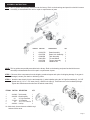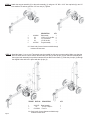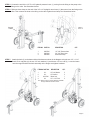
1
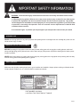
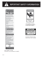
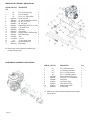
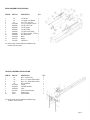
25 TON VERTICAL/HORIZONTAL LOG
SPLITTER
MODEL NO.
401625UB
Owner’s Manual
ASSEMBLY & OPERATING INSTRUCTIONS
This safety alert symbol identifies important safety messages in this manual.
Failure to follow this important safety information may result in serious injury
or death.
LS140-825-0110
Rev. 0
Table of Contents
Page(s)
Important Safety Information.................................................................................................................
1-6
Intended Use .........................................................................................................................
1
Personal Protective Equipment ...............................................................................................
1
Safety Decals .......................................................................................................................
1-2
General Safety ......................................................................................................................
3
Preparation of the Log ...........................................................................................................
3
Work Area ...........................................................................................................................
3
Operation of the Log Splitter ..................................................................................................
3-4
Repair and Maintenance Safety .............................................................................................
4
Hydraulic Safety ..................................................................................................................
5
Fire Prevention .....................................................................................................................
5-6
Towing Safety ......................................................................................................................
6
Assembly Instructions ......................................................................................................................
7-9
Parts Breakdown Illustrations................................................................................................................
10-11
Operating Instructions .......................................................................................................................
12-13
Engine Oil Recommendations ................................................................................................
12
Hydraulic Oil Recommendations ............................................................................................
12
Starting Instructions ...............................................................................................................
12
Operation ..............................................................................................................................
13
Towing ......................................................................................................................................
13
Maintenance ..........................................................................................................................................
13
Warranty and Service Information ........................................................................................................
14
Specifications ......................................................................................................................................... Back Cover
WARNING: Read and thoroughly understand all instructions and safety information before assembling
or operating this log splitter. Failure to do so may cause serious injury or death. Do not allow anyone
to operate this log splitter who has not read this manual. As with all power equipment, a log splitter
can be dangerous if assembled or used improperly. Do not operate this log splitter if you have doubts
or questions concerning safe operation. Call our customer service department at 1-800-525-8322
to address these concerns.
Si no entiende ingles, se prefiere que busque alguien que interprete las instrucciones para usted.
INTENDED USE
NEVER use this log splitter for any other purposes than splitting wood. It is designed for this use only. Any other use can
cause serious injury or death.
PEPER
PERSONAL PROTECTIVE EQUIPMENT
PERPERSONALSONAL PROTECTIVE EQUIPMENT
BEFORE operating this log splitter make sure that you wear safety gear such as goggles or safey glasses, steel toed
shoes and tight fitting gloves (without loose cuffs or draw strings). Always wear a protective hearing device when operating this log splitter.
NEVER wear loose clothing or jewelry that can be caught by moving parts of the log splitter. Keep clothing and hair away
from all moving parts when operating this log splitter.
SAFETY DECALS
Make sure that all safety warning decals are in good condition and readable. Always replace missing or defaced decals.
Contact Special Products Co. at 1-800-525-8322 for replacement decals.
PART NUMBER: 52020000
LOCATION: TOP, FRONT END OF TONGUE
Page 1
PART NUMBER: 52055200
LOCATION: BOTH STRIPPER
PLATES AND CYLINDER
PART NUMBER: 52023200
LOCATION: HYDRAULIC TANK
LOWER TANK, RIGHT CORNER
PART NUMBER: 51018900
LOCATION: TOP OF HYDRAULIC CYLINDER
Page 2
GENERAL SAFETY
Failure to follow these instructions may result in serious injury or death.
ALWAYSEread
the operator’s manual before operation. It is located in the plastic canister on the tongue.
EVER
NEVER allow children to operate this log splitter. NEVER allow adults lacking proper instructions and understanding to
operate this log splitter.
KEEP all people and pets a minimum of 10 feet away from your work area when operating this log splitter. Only the
operator is to be near the log splitter during use.
NEVER actuate the control until all people are clear of the work area.
NEVER operate the log splitter when under the influence of alcohol, drugs or medication.
NEVER allow a person who is tired or otherwise not alert to operate the log splitter.
PREPARATION OF THE LOG
Both ends of the log should be cut as square as possible to help prevent the log from riding out of the splitter during
operation. Do not split logs greater than 26 in. in length.
WORK AREA
NEVER operate the log splitter on slippery, wet, muddy or icy ground.
ONLY operate your log splitter on level ground. Operating on a slope could cause the log splitter to roll over or logs to fall
off.
NEVER operate your log splitter in an enclosed area. Exhaust fumes contain carbon monoxide which can be deadly when
inhaled.
NEVER attempt to move your log splitter over hilly or uneven terrain without a tow vehicle or adequate help.
ALWAYS block the wheels to prevent movement of the log splitter while in operation.
ONLY operate your log splitter in daylight or under good artificial light.
ALWAYS keep the work area clean. Remove split wood around your log splitter immediately so that you don’t stumble
over it.
OPERATION OF THE LOG SPLITTER
ONLY operate the log splitter from the operator zone as
shown in the diagram. The operator has the safest and
most effcient access to the control valve and the beam
in this location.Failure to operate the log splitter in this
position can result in serious injury or death.
ENGINE
TONGUE
FOOT PLATE
BEAM
OPERATOR
ZONE
Page 3
KNOW how to stop the log splitter and disengage the controls before operating it.
NEVER place hands or feet between the log and splitting wedge during forward or reverse stroke. Serious injury or death
could result.
NEVER straddle or step over the log splitter during operation.
NEVER reach or bend over the log splitter to pick up a log.
NEVER try to split two logs on top of each other.
NEVER try to cross split a log.
NEVER attempt to load your log splitter when the ram or wedge is in motion.
ALWAYS use your hand to operate the control lever on the valve. NEVER use your foot, a rope or any extension device.
NEVER move the log splitter while the engine is running. Shut off the engine even if you are leaving the log splitter for a
short period of time.
ALWAYS avoid contact with the muffler and other hot areas of the engine during operation or after running to prevent
burns.
REPAIR AND MAINTENANCE SAFETY
NEVER operate your log splitter when it is in poor mechanical condition or in need of repair.
Periodically check that all nuts, bolts, screws, hydraulic fittings and hose clamps are tight.
NEVER alter your log splitter in any manner. Such alterations may cause your log splitter to be unsafe and will void the
warranty.
Perform all recommended maintenance procedures before using your log splitter.
Replace all damaged or worn parts immediately.
NEVER tamper with the engine to run it at excessive speeds. The maximum engine speed is preset by the manufacturer
and is within safety limits. See Honda engine manual.
ALWAYS remove the spark plug wire before performing any service or repair on your log splitter.
ALWAYS check the level of hydraulic oil and engine oil before operation.
ALL replacement parts must meet manufacturer’s specifications.
Page 4
HYDRAULIC SAFETY
The hydraulic system of your log splitter requires careful inspection along with the mechanical parts. Be sure to
replace frayed, kinked, cracked or otherwise damaged hydraulic hoses or hydraulic components.
NEVER check for leaks of hydraulic fluid with your hand. Fluid escaping from a small hole can be almost invisible.
Escaping fluid under pressure can have sufficient force to penetrate skin causing serious personal injury or even death.
Leaks can be detected by passing a piece of cardboard over the suspected leak and looking for discoloration.
ALWAYS seek professional medical attention immediately if injured by escaping hydraulic fluid. Serious infection or
reaction can develop if proper medical treatment is not administered immediately.
ALWAYS be sure to relieve all pressure by shutting off the engine and moving the valve control handle back and forth
should it become necessary to loosen or remove any hydraulic fitting.
NEVER remove the cap from the hydraulic tank or reservoir while the log splitter is running. The tank could contain hot oil
under pressure which could result in serious injury.
NEVER adjust the hydraulic valve. The pressure relief valve on your log splitter is preset at the factory. Only a qualified
service technician should perform this adjustment.
FIRE PREVENTION
NEVER operate your log splitter near a flame or spark. Hydraulic oil and gasoline are flammable and can explode.
NEVER fill the gas tank while the engine is hot or running. Allow the engine to cool before refueling.
NEVER smoke while operating or refueling your log splitter. Gas fumes can easily explode.
ONLY refuel your log splitter in a clear area with no gas fumes or spilled gas.
ALWAYS use an approved fuel container.
ALWAYS replace the gas cap securely.
If gasoline has spilled, move the log splitter away from the area of the spill and avoid creating any source of ignition until
the spilled gas has evaporated.
ALWAYS take a Class B fire extinguisher with you when operating this log splitter in dry areas as a precautionary
measure against possible flying sparks.
ALWAYS drain the fuel tank prior to storage to avoid the potential fire hazard.
ALWAYS store gasoline in an approved, tightly sealed container. Store the container in a cool, dry place.
NEVER store gasoline in the house or near a heating appliance.
ALWAYS turn the fuel shut off valve on the engine to the “OFF” position before towing the log splitter. Failure to do so
may result in flooding the engine.
Page 5
IMPORTANT NOTE:
This log splitter is equipped with an internal combustion engine and should not be used on or near any unimproved
forest-covered, brush-covered or grass-covered land unless the engine’s exhaust system is equipped with a spark
arrester meeting applicable local or state laws (if any). If a spark arrester is used, it should be maintained in efffective
working order by the operator. In the state of California a spark arrester is required by law. Other states have similar laws.
Federal laws apply on federal lands. A spark arrester muffler (optional by manufacturer) is available as an accessory at
your nearest engine dealer. Always check the legal requirements in your area.
TOWING SAFETY
ALWAYS check all local and state regulations regarding towing, licensing, and lights before towing your log splitter.
ALWAYS check before towing to make sure that the log splitter is correctly and securely attached to the towing vehicle
and that the safety chains are secured to the hitch or bumper of the vehicle with enough slack to allow turning. Always
use a Class I, 2” ball with this log splitter.
NEVER carry any cargo or wood on your log splitter.
NEVER allow anyone to sit or ride on your log splitter.
ALWAYS disconnect your log splitter from the towing vehicle before operating it.
ALWAYS be careful when backing up with your log splitter in tow. It could jackknife.
ALWAYS allow for added length of your log splitter when turning, parking, crossing interesections and in all driving
situations.
NEVER exceed 45 mph when towing your log splitter. Towing the log splitter at speeds higher than 45 mph could result
in loss of control, damage to the equipment , serious injury or death. Adjust towing speed for terrain and conditions.
Be extra cautious when towing over rough terrain especially railroad crossings.
Page 6
ASSEMBLY INSTRUCTIONS
NOTE: This log splitter was partially assembled at the factory. Refer to the drawings and parts list should it become
necessary to disassemble the unit for repair or replacement of parts
ITEM NO.
1
2
3
4
5
PART NO.
401611R0
40127500
40160900
400312B0
40127300
40115400
DESCRIPTION
Beam Assembly
Beam Lock Assembly
Tank Assembly
Tire and Wheel
Tongue Assembly
Hardware Kit
QTY.
1
1
1
2
1
1
NOTE: This log splitter was partially assembled at the factory. Refer to the drawing and parts list should it become
necessary to disassemble the unit for repair or replacement of parts.
STEP 1: Remove all the components from the shipping container.Inspect each piece for shipping damage. If any part is
damaged, contact your dealer or delivering carrier.
STEP 2: Attach the two wheels (2) to the tank assembly (1) wheel spindles using the 3/4” light flat washers(3) , 3/4” NF
slotted nuts (4), 1/8” x 1-1/2” cotter pins (5) and the hub caps (6). These items are in the hardware package.
Tighten the slotted nuts and make sure the wheels rotate freely.
ITEM NO. PART NO. DESCRIPTION
QTY.
1
2
3
4
5
6
1
2
2
2
2
2
40160900 Tank Assembly
400312B0 Wheel Assembly
O/L
3/4” Light Flatwasher
17012000 3/4” Slotted Nut
O/L
1/8” x 1-1/2” Cotter Pin
40033200 Hub Cap
O/L- Obtain locally. Common fasteners available through
hardware and farm stores.
Page 7
STEP 3: Attach the tongue assembly (5) to the tank assembly (1) using two 1/2” NC x 4-1/2” hex cap bolts (2), two 1/2”
lock washers (3) and two and two 1/2” hex nuts (4). Tighten.
ITEM NO. PART NO. DESCRIPTION
QTY.
1
40160900
TankAssembly
1
2
O/L
1/2” NC x 4-1/2 Hex Bolt 2
3
O/L
1/2” Lock Washer
2
4
O/L
1/2” NC Hex Nut
2
5
40127300
Tongue Assembly
1
O/L- Obtain locally. Common fasteners available through
hardware and farm stores.
STEP 4: Stand the beam (1) up on end. Two people may be needed for this step to ensure safety. Make sure that the
beam is stable and on a level surface. Remove the pivot pin (3) and clip pin (2) from the tank assembly.Roll
the tongue/ tank assembly into position between the two tabs on the beam (1). Slide the pivot pin (3) through
the aligned holes and lock in place with the clip pin (2).
ITEM NO. PART NO.
1
2
3
Page 8
DESCRIPTION
401611R0 Beam Assembly
O/L
1/2”-3/4” R Clip Pin
071022WC Pivot Pin
O/L- Obtain locally. Common fasteners available through
hardware and farm stores.
QTY
1
1
1
STEP 5: Connect the end of the 1/2” ID x 44” hydraulic pressure hose (1) coming from the fitting on the pump to the
fitting on the valve. See illustrations below.
STEP 6: Slide one hose clamp on the end of the 3/4” x 44” hydraulic return hose (2 ) that comes from the fitting on the
filter. Then connect the hose to the fitting on the valve.Tighten hose clamp. See illustrations below.
Area of
Detail
STEP 7:
`
DETAIL A
SCALE 1:3
ITEM NO. PART NO.
DESCRPTION
QTY.
1
2
3
1/2” X 38” Pressure Hose
3/4” x 56” Return Hose
Worm Gear Clamp
1
1
3
39027500
39027400
39031600
Attach the latch (3) to the bottom side of the beam as shown in the diagram using the two 1/2” x 1-1/4”
Grade 5 hex cap bolts (4), the two 1/2” lock washers (1) and the two 1/2” hex nuts (2 ). Lower the beam
onto the tongue.Position the latch assembly on the tongue and tighten hardware.
ITEM NO. PART NO.
1
2
3
4
O/L
O/L
40127500
O/L
DESCRIPTION
QTY.
1/2” Lock Washer
1/2” Hex Nut
Beam Lock
1/2” x 1-1/4” Bolt
2
2
1
2
O/L- Obtain locally. Common fasteners available
through hardware and farm stores.
Page
9 9
Page
TANK/ENGINE ASSEMBLY BREAKDOWN
ITEM NO. PART NO.
QTY.
DESCRIPTION
1
2
3
4
5
6
7
8
9
10
10
11
12
13
14
15
16
17
5/16”-18 UNC Nylock Nut
5/16” Flat Washer
5/16” x 1-1/2” GR5 Hex Bolt
Return Line Hose
1/2” x 38” Hydraulic Pressue Hose
3/4” NPT x 3/4” Tube
3/4” Hex Nipple
Straight Fitting, 3/4”NPT to 1/2” Tube
1” ID Suction Hose
Filter Base
Filter Element
Briggs & Stratton 1450/Pump Assy.
Worm Gear Clamp
Tank
Pivot Pin
1/2”-3/4” Hairpin Cotter
Dip Stick/Breather Cap
Filter Element
O/L
O/L
O/L
39027400
39027500
39032000
39034900
39038100
39038900
390604B0
390601A0
39073200
39031600
40118800
071022WC
O/L
3903750
390601A0
4
8
4
1
1
1
1
1
1
1
1
1
3
1
1
1
1
1
10A
O/L- Obtain locally. Common fasteners available through
hardware and farm stores.
PUMP/ENGINE ASSEMBLY BREAKDOWN
ITEM NO. PART NO.
DESCRIPTION
QTY.
1
2
3
4
5
6
7
8
9
10
11
5/16”-18 UNC Nylock Nut
5/16” Regular Lock WAsher
5/16” x 1-1/4”GR5 Hex Bolt
5/16” x 1 UNF GR5 Hex Bolt
Briggs & Stratton 1450 Engine
1/4” Square x 1-1/2” Square Key
Pump Mount
Jaw Coupler 1” Bore
Jaw Coupler 1/2” Bore
Rubber Coupler Spider
16 GPM Pump
4
4
4
4
1
1
1
1
1
1
1
O/L
O/L
O/L
O/L
39054500
40034300
40081800
400825L0
400826L0
400827L0
39070900
O/L- Obtain locally. Common fasteners available through hardware
and farm stores.
Page 10
BEAM ASSEMBLY BREAKDOWN
ITEM NO. PART NO.
DESCRIPTION
1
2
3
4
5
6
7
8
9
10
11
12
13
1/2” Hex Nut
1
1/2” Regular Lock Washer
1
1/2” x 3-1/4” Hex Bolt
1
4.5” x 24” Hydraulic Cylinder 1
3/4” NPT x 3/4” Tube
1
1/2” NPT Nipple
1
1/2” Steel Tubing
1
1/2” Pipe to Steel Tubing
2
45° Fitting, 34” Male, 1/2” Fem. 1
Auto-Return Valve
1
Beam
1
Wedge
1
Cylinder Pin
1
O/L
O/L
O/L
390119B0
39032000
39034300
39034600
39034700
39039000
390406A0
401414R0
40141700
07073100
QTY
O/L- Obtain locally. Common fasteners available through
hardware and farm stores.
TONGUE ASSEMBLY BREAKDOWN
ITEM NO. PART NO.
DESCRIPTION
QTY.
1
2
3
4
5
6
7
8
9
10
M10 x 1.5 Nylock Nut
M10 x 1.5 x 100mm GR5 Hex Bolt
M10 x 1.5 x 120mm GR5 Hex Bolt
M10 Flat Washer
Tongue
Hitch Ball Assembly
Chain
Ground Stand Assembly
Retaining Ring
Spacer Washer
2
1
1
5
1
1
2
1
1
1
O/L
O/L
O/L
O/L
401273A0
40034600
400323A0
40127400
9114-1
9132-1
O/L- Obtain locally. Common fasteners available through
hardware and farm stores.
Page 11
OPERATING INSTRUCTIONS
WARNING: Read and thoroughly understand all instructions and safety information before operating
this log splitter. Failure to do so may cause serious injury or death. Do not allow anyone to operate
this log splitter who has not read this manual. As with all power equipment, a log splitter can be
dangerous if assembled or used improperly. Do not operate this log splitter if you have doubts or
questions concerning safe operation. Call our customer service department at 1-800-525-8322 to
address these concerns.
Si no entiende ingles, se prefiere que busque alguien que interprete las instrucciones para usted.
CAUTION:
DO NOT START OR RUN THE ENGINE BEFORE ADDING OIL IN THE HYDRAULIC RESERVOIR AND OIL IN
THE ENGINE.
STEP 1: The hydraulic reservoir must be filled with oil before operation. AW46 hydraulic oil is recommended when oil is needed. Automatic
transmission fluid can be substituted and should be used instead of hydraulic oil when temperatures are below 32 degrees F. Use only
clean oil and take care to prevent dirt from entering the hydraulic reservoir. Fill the hydraulic tank with approximately 3.5 to 4.0 gallons of
hydraulic fluid
CAUTION:
WHEN TIGHTENING THE BREATHER CAP ON THE TANK, POINT THE HOLE AWAY FROM THE ENGINE
AND THE OPERATOR ZONE.
ENGINE OIL RECOMMENDATIONS
For temperatures above 40 degrees F use an SAE 30W oil. Using mutigrade oil may increase oil consumption. Using SAE 30W oil below 40 degrees
F will resuilt in hard starting and possible engine bore damage.For temperatures below 40 degrees F use an SAE 10W-30 or SAE 5W-30 oil. Oil
capacity is about 1.16 quart (1.1 liter).
STEP 2: After the hydraulic reservoir and the engine crankcase are filled with oil, start the engine. The hydraulic pump should prime itself. With the
engine running, move the hydraulic valve lever toward the foot plate. This will cause the cylinder to extend and expel air. When the cylinder
is fully extended, retract it. Repeat this procedure several times. An erratic movement of the cylinder indicates that there is still air in the
system. Add about 1.0 to 1.5 gallons more. Five gallons will register just above the top fill line on the dip stick.The total capacity of the entire
hydraulic system is 6.5 gallons. NOTE: If the tank is overfilled it will tend to expel oil from the breather cap when the cylinder is retracted.
Cycle the cylinder again until it has a constant speed indicating that all air has been expelled.
STARTING INSTRUCTIONS
Refer to the Briggs & Stratton Owner’s manual for complete information on starting, maintenance and specifications.
1450 Briggs & Stratton Engine
a) Move the throttle lever to “FAST”. Always operate the engine with throttle lever in the “FAST” position
b) Move choke control lever to “CHOKE” position.
c) Grasp rope handle and pull slowly until resistance is felt. Then pull rapidly to start engine and avoid engine kickback.
d) Allow the engine to warm up. If operating in warm weather, move the choke control lever toward “RUN” a short distance at a time over
several seconds. For cold weather operation do this procedure over several minutes. Operate with choke lever in the “RUN” position.
e) To stop engine, move the throttle lever to the “STOP” position.
Page 12
CAUTION: TURN FUEL SHUT OFF VALVE TO THE “OFF” POSITION PRIOR TO TOWING.FAILURE TO DO SO MAY RESULT IN
FLOODING THE ENGINE.
NOTE:
The engine maximum governed speed is preset at the factory at 3600 RPM no load speed. When splitting wood the throttle
should be set at the maximum speed to develop the horsepower required for the pump.
OPERATION
WARNING: See safety information related to operation of the log splitter on page 3 and 4 of this manual. Make sure that you have the
recommended personal protective equipment described on page 1.
1) Set up the log splitter in a clear, level area and block the wheels. Make sure that the suction port on the tank is always on the lower side
of the log splitter.
2) For horizontal operation place a log on the beam against the foot plate. Make sure the the log is securely on the foot plate and up against the
beam.To split wood in the vertical position, release the pin on the beam latch located near the front end of the beam. Carefully tilt the beam up until
the foot plate is sitting squarely on the ground and the log splitter is stable. Place the log on the foot plate up against the beam. When the beam is
returned to the horizontal position make sure the beam latch is securely locked down. See illustrations in Step 7 on page 9.
3) With the engine running, depress the valve handle so that the cylinder will drive the wedge into the log. Extend the cylinder until the log splits or to
the end of its stroke. If the log has not completely split after the cylinder has reached the end of its extension, retract the cylinder.
IMPORTANT: Leaving the valve in the “actuate” position at the end of the stroke may damage the pump. Always use extra care when splitting
logs with unsquare ends.
NOTE:
For operation in wooded areas, obtain a spark arrestor for the exhaust system. See the engine operating and maintenance manual and
check with your authorized Briggs & Stratton service center. See also Fire Prevention on page 5 of this manual.
IMPORTANT:
TO EXTEND THE LIFE OF THE HYDRAULIC CYLINDER, AVOID “BOTTOMING OUT” WEDGE PLATE TO THE FOOT
PIECE. TO CONFORM WITH INDUSTRY SAFETY RECOMMENDATIONS, THE WEDGE STOPS 1.5 INCHES FROM
THE END OF THE STROKE.
TOWING
This log splitter is equipped with pneumatic tires, a Class I coupler (2 in. diameter ball required) and safety chains. Before towing, the safety chains
must be secured to the hitch or bumper of the vehicle. Local regulations should be checked regarding licensing, lights, towing, etc.Turn fuel shut off
valve on the engine to the “Off” position prior to towing. Failure to do so may result in flooding the engine. Do not exceed 45 mph when towing this
log splitter. See also Towing Safety on page 6 of this manual.
MAINTENANCE
1) Consult the operating and maintenance instructions of the engine manufacturer for engine care and maintenance.
2) Always check the oil level of the hydraulic reservoir before operation. Operating the log splitter without an adequate oil supply will cause
severe damage to the pump.
3) Change the oil filter after the first 25 hours of operation. There after change the oil filter every 100 hours or seasonally, whichever comes first.
4) To drain the hydraulic oil, loosen the clamp on the hose coming from the fitting on the bottom of the tank. It is located just to the right of the oil
filter.
5) If the wedge becomes dull or nicked, it can be removed and sharpened. Remove the 1/2 in. diameter bolt that connects the wedge to the cylinder.
hose from the valve. The hose from the valve may need to be removed. Carefully lift the cylinder to allow the wedge to slide forward. The wedge
can now be lifted off and sharpened.
6) Clean the breather cap after 25 hours of operation. Clean it more often when operated in dusty conditions. To clean, remove the breather cap
from the tank and flush with kerosene or liquid detergent to remove the dirt.
7) See also Repair and Maintenance Safety on page 4 of this manual.
8) All replacement parts must meet manufacturer’s specifications.
Page 13
IMPORTANT NOTICE
We, the manufacturer, reserve the right to change the product and/or specifications in this manual without notification.
The manual is for information usage only and the pictures and drawings depicted herein are for reference only.
NOTES
Warranty Repair and Service
Do not return this product to the store for warranty issues or repair. Call 1-800-525-8322 for the location of the
nearest service center.
Record the information below for future reference.
Model No. ____________________
Serial No. _____________________________
Date of Purchase _______________
Place of Purchase _______________________
_______________________
_______________________
_______________________
Page 14
SPECIFICATIONS
Engi ne
Pump
C yli nder
Valve
Bri ggs & Stratton 1450 Engi ne
Two-Stage, 16 gpm
4-1/2 i n. D i ameter x 24 i n. Stroke
Auto-Return
Maxi mum Spli tti ng Force
25 Tons
Maxi mum Log Length
C ycle Ti me*
26 i n.
12 Seconds
Wheels
4.80 x 8 i n.
Wedge
7 i n. Hi gh wi th Spreader Wi ngs
Beam Si ze
Hydrauli c C apaci ty
6 i n. x 9 i n. wi th Bui lt-In Log C radle
6.5 Gallons Maxi mum
Fi lter
Spi n-On Replaceable Fi lter
Hei ght
72 i n. i n Verti cal Posi ti on
42 i n. i n Hori zontal Posi ti on
Length
78 i n.
Wi dth
49 i n.
Shi ppi ng Wei ght
590 lbs.
*Ideal case cycle ti me. Actual cycle ti me wi ll vary dependi ng on
temperature, alti tude, engi ne speed, pump effi ci ency, etc.
AA
Part No. 52070800