1
CardAccess Wireless Locks
ADDENDUM to the
CA3000 USER MANUAL
WIRELESS LOCK HARDWARE GUIDE
DATE:
2 AUGUST 2011
LOCK MODELS:
ALARM LOCK "PDL6100" / CONTINENTAL "CPDL6100"
ALARM LOCK "PL6100" / CONTINENTAL "CPL6100"
DOCUMENT PERTAINS TO:
WIRELESS LOCK LED AND SOUNDER INDICATORS;
WIRING, POWER UP, AND BATTERY REPLACEMENT
PROCEDURES
CardAccess
© Continental 2011
Wireless Lock Hardware Guide
WI1969 8/11
1
FCC WARNING
Changes or modifications to this unit not expressly approved by the party responsible for compliance could void the
user’s authority to operate the equipment.
NOTE
This equipment has been tested and found to comply with the limits for a Class A digital device, pursuant to Part 15 of
the FCC Rules. These limits are designed to provide reasonable protection against harmful interference when the
equipment is operated in a commercial environment. This equipment generates, uses, and can radiate radio frequency
energy and, if not installed and used in accordance with the instruction manual, may cause harmful interference to radio communications. Operation of this equipment in a residential area is likely to cause harmful interference in which
the user will be required to correct the interference at his own expense.
Shielded cables must be used with this unit to ensure compliance with the Class A FCC limits.
"This digital apparatus does not exceed the Class A limits for radio noise emissions from digital apparatus set out in the
Radio Interference Regulations of the Canadian Department of Communications.”
Le present appareil numerique n’ émet pas de bruits radioélectriques dépassant les limites applicables aux appareils
numeriques de la class A prescrites dans le Réglement sur le brouillage radioélectriques edicté par le ministere des
Communications du Canada.
DISCLAIMER
Continental Instruments LLC makes no representations or warranties with respect to the contents hereof and specifically disclaims any implied warranties of merchantability or fitness for any particular purpose. Further, Continental Instruments LLC reserves the right to revise this publication and to make changes from time to time in the content hereof
without obligation of Continental Instruments LLC to notify any person of such revision or changes. If possible, always
refer to the Continental Access website (www.cicaccess.com; click Support) for the latest documentation, as the released CD may not contain the latest documentation.
Copyright © 2011 by Continental Instruments LLC. All rights reserved. No part of this publication may be reproduced, transmitted, transcribed, or stored in a retrieval system, without the prior written permission of Continental Instruments LLC, 355 Bayview Avenue, Amityville, NY 11701. Telephone: 631-842-9400 • FAX: 631-842-9135 • GSA#
GS-07F-0039H.
ProxCard® and ProxKey® are trademarks of the HID© Corporation. Microsoft® and Windows® are trademarks of their
the Microsoft Corporation. Trilogy® is a registered trademark of Alarm Lock. All other trademarks, service marks, and
product or service names described in this manual are for identification purposes only and may be trademarks or registered trademarks of their respective owners.
The absence of a name or logo in this document does not constitute a waiver of any and all intellectual property rights
that NAPCO Security Technologies, Inc. or Continental Instruments LLC has established in any of its product, feature,
or service names or logos.
This document contains proprietary information of NAPCO Security Technologies. Unauthorized reproduction of any
portion of this manual without the written authorization of NAPCO Security Technologies is prohibited. The information
in this manual is for informational purposes only. It is subject to change without notice. Companies, names and data
used in examples herein are fictitious unless otherwise noted. NAPCO Security Technologies assumes no responsibility for incorrect information this manual may contain.
A NAPCO SECURITY TECHNOLOGIES COMPANY
Publicly traded on NASDAQ
Symbol: NSSC
Visit our websites at
http://www.cicaccess.com/
http://www.napcosecurity.com/
http://www.alarmlock.com/
2
Wireless Lock Hardware Guide
Table of Contents
Lock Specifications .................................................................................................................................. 2
Alarm Lock PDL6100 / Continental CPDL6100 ...................................................................................... 4
Overview ......................................................................................................................................... 4
Wiring .............................................................................................................................................. 4
First Time Power Up ...................................................................................................................... 4
Erase All Programming (Manual Default) .................................................................................... 4
Power Re-Applied .......................................................................................................................... 4
Battery Replacement ..................................................................................................................... 5
LED and Sounder Indicators ........................................................................................................ 5
Alarm Lock PL6100 / Continental CPL6100............................................................................................ 6
Overview ......................................................................................................................................... 6
Wiring .............................................................................................................................................. 6
First Time Power Up ...................................................................................................................... 6
Erase All Programming (Manual Default) .................................................................................... 6
Power Re-Applied .......................................................................................................................... 6
Battery Replacement ..................................................................................................................... 7
LED and Sounder Indicators ........................................................................................................ 7
Warranty ..................................................................................................................................................... 8
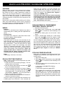
Lock Specifications
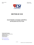
● CPDL6100 - Cylindrical Trilogy® Networx™ Wireless Access Control Lock with built in HID Proximity ID Card Reader, fullmetal digital keypad, integral bi-directional radio, 4 C-cell battery-operated (batteries supplied), serial number ID card,
standard format SCI keyway for manual key override, 4⅞" ASA Strike (included).
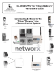
● CPL6100 - Cylindrical Trilogy® Networx™ Wireless Access Control Lock with built in HID Proximity ID Card Reader
(keypad removed for added security), integral bi-directional radio, 4 C-cell battery-operated (batteries supplied), serial
number ID card, standard format SCI keyway for manual key override, 4⅞" ASA Strike (included).
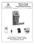
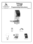
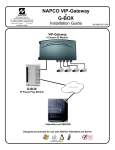
"STAR" (:) Key
Red LED
Green LED
"AL" (;) Key
Card Reader
Red LED
Green LED
Card Reader
Metal Key
Override
Metal Key
Override
PDL6100 / CPDL6100
Wireless Lock Hardware Guide
PL6100 / CPL6100
3
Alarm Lock PDL6100 / Continental CPDL6100
OVERVIEW
When an Alarm Lock door lock is removed from its factory
packaging and powered, it contains Alarm Lock firmware;
this manual will refer to these "factory-fresh" models as
"PDL" or "PL" (for example "PDL6100"). Locks converted to
the CA3000 system have the letter "C" added before the
"PDL" or "PL" letters (for example, an Alarm Lock model
"PDL6100" becomes a "CPDL6100" when converted for use
with CA3000.
Notice that the next section details powering up the factory
Alarm Lock model PDL6100; once the lock is converted to
the CA3000 system, all subsequent sections then detail the
converted Continental lock model CPDL6100.
WIRING
Batteries:
Use four 1.5 volt Alkaline size-C batteries only (either a
sealed battery pack or battery pack with replaceable batteries).
External Power:
Red / Black wires - External 7.5 VDC Power Source must
be used for operation without batteries.
Remote Input / Bypass:
(Two white wires) In the rear of the lock body are two
white wires that, when shorted, cause the lock to unlock,
(thus "unlocking the door" and allowing passage through
the protected door). These two white wires are called
"Remote Input" in Alarm Lock terminology, and called
"Bypass" in Continental terminology. Wire a normallyopen switch to the two white wires; momentarily close to
unlock / allow passage / entry through door. NOTE: By
default, Remote Input is enabled in the Alarm Lock
PDL6100 from the factory and also enabled when
converted to the Continental CPDL6100.
Relay:
COM-Orange / NO-Green / NC-Yellow.
PDL6100 FIRST TIME POWER UP
Note: Failure to follow the exact steps below can result
in erratic lock behavior.
1. Unpack the lock from its factory packaging. The lock
contains Alarm Lock firmware.
2. With the batteries disconnected, hold down the ;
key for 10 seconds and release.
3. Connect the batteries and listen for 3 beeps. Within 5
seconds of hearing the 3 beeps, press and hold ;
until beeping starts. This will clear the lock of all programmed data. Important: If you do not hear these 3
beeps, you must start over at step 2.
4. Listen for another series of beeps and LED flashes followed by 10 seconds of silence.
before the lock receives a full data download from
CA3000 (badge data, etc), only one user code is programmed into the lock ("123456") to allow the lock to
unlock for 6 seconds. Also, Remote Input / Bypass is
enabled (see "WIRING" above).
From this point onward, the text in these instructions
assume the lock has been discovered and converted
to the CA3000 system as a CPDL6100 using the Wireless Lock Integration Guide WI1949 (section "Quick
Start: Add Gateways and Locks").
--------------------------------------------------------------------------
CPDL6100 ERASE ALL PROGRAMMING
(PERFORM A "MANUAL DEFAULT")
1. Disconnect the battery pack.
2. With battery power disconnected, press and hold
down ; for 10 seconds to ensure discharge of all
capacitors.
3. Re-install the battery pack; lock will sound 3 short
beeps.
4. Within 5 seconds after hearing the 3 short beeps,
press and hold ; until the lock begins to beep
slowly (7 red LED flashes with 7 beeps), then release.
All lock configuration data (badge data, access groups,
etc.) have been erased and the lock is now ready to be
discovered and added to the CA3000 system. Before the
lock receives a full data download from CA3000 (badge
data, etc), only one user code is programmed into the
lock ("123456") to allow the lock to unlock for 6 seconds.
Also, Remote Input / Bypass is enabled (see "WIRING"
above).
CPDL6100 POWER RE-APPLIED
When power is re-applied to a lock that has already been
configured and operational (with badge data, etc.), proceed as follows:
1. Disconnect battery pack.
2. With battery power disconnected, press and hold
down ; for 10 seconds to insure discharge of all
capacitors.
3. Re-connect battery pack, do not touch any keys. Observe lock carefully:
•
•
•
3 short beeps sound (NO LED's flashing);
short pause;
3 short beeps sound with 3 green LED's.
The 3 green LED's indicate the lock configuration
data (badge data, etc.) is retained successfully, and
the lock is ready for use. If you see 3 red LED's, this
indicates the lock started without configuration data,
and will automatically request configuration data from
CA3000.
The lock is ready to be discovered and converted to the
CA3000 system as a CPDL6100. Once converted, but
4
Wireless Lock Hardware Guide
Alarm Lock PDL6100 / Continental CPDL6100
CPDL6100 BATTERY REPLACEMENT
Upon a credential presentation (badge or code) when the
batteries are weak, the lock sounder will continuously
beep for the length of the "Door Strike Time" ("Door
Strike Time" is the duration the lock would remain
unlocked when a valid badge is presented). For models
with a replaceable battery pack, use four (4) C-size 1.5
volt alkaline batteries. For models with a sealed battery
pack, contact your Alarm Lock dealer for a replacement
battery pack. Always replace weak batteries as soon as
possible.
1. At the back of the lock, remove the screw at the bottom of the lock housing and remove the cover.
2. Disconnect the battery pack, removing power.
3. With battery power disconnected, press and hold
down ; for 10 seconds to ensure discharge of all
capacitors.
4. Re-connect battery pack, do not touch any keys. Observe lock carefully:
•
•
•
3 short beeps sound (NO LED's flashing);
short pause;
3 short beeps sound with 3 green LED's.
The 3 green LED's indicate the lock configuration
data (badge data, etc.) is retained successfully, and
the lock is ready for use. If you see 3 red LED's, this
indicates the lock started without configuration data,
and will automatically request configuration data from
CA3000.
5. Replace the cover and tighten the screw.
Note: Restarting an operational lock may send a Lock
Startup event to the CA3000 GUI.
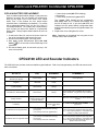
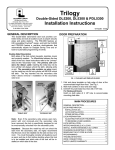
CPDL6100 LED and Sounder Indicators
The CPDL6100 lock provides visual and audible keypad feedback. With a fully charged battery, the LED and sounder feedback is as follows:
ACTIVITY
LED
SOUNDER
COMMENTS
Valid Credential or
Remote Input / Bypass
3 Green Flashes
3 Beeps
Normal Operation
Keypress
1 Red Flash
1 Beep
Invalid Credential
7 Red Flashes
7 Beeps
Card Detection / Reader Disabled
2 Red Flashes
2 Beeps
"Card Detection": Badge presented to lock reader to
test if the badge type is compatible with the system.
"Reader Disabled": Programmed using CA3000 software.
Waiting Indication
Slow green flashes for programmed duration (varies
with reader settings)
--
Used when "Card & Code" or "Two Person Reader" is
enabled
Low Battery
--
Continuous beep for
length of "Door Strike
Time"
See "CPDL6100 BATTERY REPLACEMENT" on this
page above.
Lock Restarts with Configuration Data
• 3 short beeps sound (NO LED's flashing);
• short pause;
• 3 short beeps sound with 3 green LED's.
When power re-applied to a lock that has already
been configured and operational (with badge data,
etc.), or when replacing batteries. Configuration data
retained, no need for data download.
Lock Restarts without Configuration Data
• 3 short beeps sound (NO LED's flashing);
• short pause;
• 3 short beeps sound with 3 red LED's.
When power re-applied to a lock that has already
been configured and operational (with badge data,
etc.), or when replacing batteries. Configuration data
lost or corrupted, lock will automatically request configuration data from CA3000.
Wireless Lock Hardware Guide
5
Alarm Lock PL6100 / Continental CPL6100
OVERVIEW
When an Alarm Lock door lock is removed from its factory
packaging and powered, it contains Alarm Lock firmware;
this manual will refer to these "factory-fresh" models as
"PDL" or "PL" (for example "PL6100"). Locks converted to
the CA3000 system have the letter "C" added before the
"PDL" or "PL" letters (for example, an Alarm Lock model
"PL6100" becomes a "CPL6100" when converted for use
with CA3000.
Notice that the next section details powering up the factory
Alarm Lock model PL6100; once the lock is converted to the
CA3000 system, all subsequent sections then detail the converted Continental lock model CPL6100.
WIRING
Batteries:
Use four 1.5 volt Alkaline size-C batteries only (either a
sealed battery pack or battery pack with replaceable batteries).
External Power:
Red / Black wires - External 7.5 VDC Power Source must
be used for operation without batteries.
Remote Input / Bypass:
(Two white wires) In the rear of the lock body are two
white wires that, when shorted, cause the lock to unlock,
(thus "unlocking the door" and allowing passage through
the protected door). These two white wires are called
"Remote Input" in Alarm Lock terminology, and called
"Bypass" in Continental terminology. Wire a normallyopen switch to the two white wires; momentarily close to
unlock / allow passage / entry through door.
Relay:
COM-Black / NO-White / NC-Yellow.
Erase Memory Leads:
Yellow / Yellow wires - When shunted during power up,
the Lock Program memory is erased (see ERASE ALL
PROGRAMMING below).
PL6100 FIRST TIME POWER UP
Note: Failure to follow the exact steps below can result in
erratic lock behavior.
When powered for the first time but before it is converted
to the CA3000 system as a CPL6100, the PL6100 will remain unlocked.
1. Unpack the lock from its factory packaging.
2. For models with a replaceable battery pack, install
fresh batteries with attention to the correct polarity as
indicated inside the plastic battery pack housing. Do
not connect the batteries yet.
3. With battery power disconnected, short the two white
wires (Remote Input / Bypass wires) together for 10
seconds to ensure discharge of all capacitors. After 10
6
seconds, remove the short.
4. Plug in the (provided) male shunt connector into the
yellow wire female connector (Erase Memory Leads).
5. With shunt connector connected, re-connect the battery pack. The lock will immediately sound 3 short
beeps (if these 3 beeps are not heard, then restart at
step 3).
6. The lock will then sound more slow beeps, 1 beep for
every second it takes to clear the memory.
7. After 2 rapid beeps are heard and 2 green LED flashes
are seen,
8. REMOVE YELLOW MALE SHUNT connector (Erase
Memory Leads).
The lock is ready to be discovered and converted to the
CA3000 system as a CPL6100. Once converted, but before the lock receives a full data download from CA3000
(badge data, etc), and the CPL6100 is unlocked by default.
From this point onward, the text in these instructions
assume the lock has been discovered and converted
to the CA3000 system as a CPL6100 using the Wireless Lock Integration Guide WI1949 (section "Quick
Start: Add Gateways and Locks").
--------------------------------------------------------------------------
CPL6100 ERASE ALL PROGRAMMING
(PERFORM A "MANUAL DEFAULT")
1. At the back of the lock, remove the lock housing screw
and remove the cover.
2. Take out battery pack and remove battery power by
disconnecting the battery pack plug.
3. With battery power disconnected, short the two white
wires (Remote Input / Bypass wires) together for 10
seconds to ensure discharge of all capacitors. After
10 seconds, remove the short.
4. Plug in the (provided) male shunt connector into the
yellow wire female connector (Erase Memory Leads).
5. With shunt connector connected, re-connect the battery pack. The lock will immediately sound 3 short
beeps.
6. The lock will then sound more slow beeps, 1 beep for
every second it takes to clear the memory.
7. REMOVE YELLOW MALE SHUNT connector (Erase
Memory Leads).
With the yellow male shunt connector removed, all lock
configuration data (badge data, access groups, etc.) have
been erased and the lock is now ready to be discovered
and added to the CA3000 system. Before the lock receives a full data download from CA3000 (badge data,
etc), the CPL6100 is unlocked by default.
CPL6100 POWER RE-APPLIED
When power is re-applied to a lock that has already been
configured and operational (with badge data, etc.), and
you wish to retain the Lock Program (such as when movWireless Lock Hardware Guide
Alarm Lock PL6100 / Continental CPL6100
ing an existing lock to a new door, and the lock must be
dismantled and powered down for an extended time period), proceed as follows:
1. Disconnect battery pack connector.
2. With battery power removed, short the two white wires
(Remote Input / Bypass wires) together for 10 seconds to ensure discharge of all capacitors.
Do NOT plug in the yellow wire shunt connector
(Erase Memory Leads--DO NOT CONNECT).
3. Re-connect battery pack (lock will sound 3 short
beeps). If these 3 beeps are not heard, then repeat
steps at step 1. Observe lock carefully:
•
•
•
3 short beeps sound (NO LED's flashing);
short pause;
3 short beeps sound with 3 green LED's.
The 3 green LED's indicate the lock configuration
data (badge data, etc.) is retained successfully, and
the lock is ready for use. If you see 3 red LED's, this
indicates the lock started without configuration data,
and will automatically request configuration data from
CA3000.
CPL6100 BATTERY REPLACEMENT
Upon a badge presentation when the batteries are weak,
the lock sounder will continuously beep for the length of
the "Door Strike Time" ("Door Strike Time" is the duration
the lock would remain unlocked when a valid badge is
presented). For models with a replaceable battery pack,
use four (4) C-size 1.5 volt alkaline batteries. For models
with a sealed battery pack, contact your Alarm Lock
dealer for a replacement battery pack. Always replace
weak batteries as soon as possible.
1. At the back of the lock, remove the screw at the bottom of the lock housing and remove the cover.
2. Disconnect the battery pack, removing power.
3. With battery power removed, short the two white wires
(Remote Input / Bypass wires) together for 10 seconds to ensure discharge of all capacitors.
Do NOT plug in the yellow wire shunt connector
(Erase Memory Leads--DO NOT CONNECT).
4. Re-connect battery pack and observe lock carefully:
•
•
•
3 short beeps sound (NO LED's flashing);
short pause;
3 short beeps sound with 3 green LED's.
The 3 green LED's indicate the lock configuration data
(badge data, etc.) is retained successfully, and the
lock is ready for use. If you see 3 red LED's, this indicates the lock started without configuration data, and
will automatically request configuration data from
CA3000.
5. Replace the cover and tighten the screw.
Note: Restarting an operational lock may send a Lock
Startup event to the CA3000 GUI.
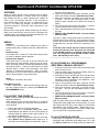
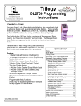
CPL6100 LED and Sounder Indicators
With a fully charged battery, the CPL6100 LED and sounder feedback is as follows:
ACTIVITY
LED
SOUNDER
COMMENTS
Valid Credential or
Remote Input / Bypass
3 Green Flashes
3 Beeps
Normal Operation
Invalid Credential
7 Red Flashes
7 Beeps
Card Detection / Reader Disabled
2 Green Flashes
2 Beeps
"Card Detection": Badge presented to lock reader to test if
the badge type is compatible with the system.
"Reader Disabled": Programmed using CA3000 software.
Waiting Indication
Slow green flashes for programmed duration (varies
with reader settings)
--
Used when "Card & Code" or "Two Person Reader" is
enabled
Low Battery
--
Continuous beep for
length of "Door Strike
Time"
See "CPL6100 BATTERY REPLACEMENT" on this page
above.
Lock Restarts with Configuration Data
• 3 short beeps sound (NO LED's flashing);
• short pause;
• 3 short beeps sound with 3 green LED's.
When power re-applied to a lock that has already been
configured and operational (with badge data, etc.), or
when replacing batteries. Configuration data retained, no
need for data download.
Lock Restarts without Configuration Data
• 3 short beeps sound (NO LED's flashing);
• short pause;
• 3 short beeps sound with 3 red LED's.
When power re-applied to a lock that has already been
configured and operational (with badge data, etc.), or
when replacing batteries. Configuration data lost or corrupted, lock will automatically request configuration data
from CA3000.
Wireless Lock Hardware Guide
7
ALARM LOCK LIMITED WARRANTY
ALARM LOCK SYSTEMS, INC. (ALARM LOCK)
warrants its products to be free from manufacturing
defects in materials and workmanship for 24 months
following the date of manufacture. ALARM LOCK will,
within said period, at its option, repair or replace any
product failing to operate correctly without charge to the
original purchaser or user.
This warranty shall not apply to any equipment, or any
part thereof, which has been repaired by others,
improperly installed, improperly used, abused, altered,
damaged, subjected to acts of God, or on which any
serial numbers have been altered, defaced or removed.
Seller will not be responsible for any dismantling or
reinstallation charges.
THERE ARE NO WARRANTIES, EXPRESS OR
IMPLIED, WHICH EXTEND BEYOND THE
DESCRIPTION ON THE FACE HEREOF. THERE IS
NO EXPRESS OR IMPLIED WARRANTY OF
MERCHANTABILITY OR A WARRANTY OF FITNESS
FOR A PARTICULAR PURPOSE. ADDITIONALLY,
THIS WARRANTY IS IN LIEU OF ALL OTHER
OBLIGATIONS OR LIABILITIES ON THE PART OF
ALARM LOCK.
Any action for breach of warranty, including but not
limited to any implied warranty of merchantability, must
be brought within the six months following the end of
the warranty period. IN NO CASE SHALL ALARM
LOCK BE LIABLE TO ANYONE FOR ANY
CONSEQUENTIAL OR INCIDENTAL DAMAGES FOR
BREACH OF THIS OR ANY OTHER WARRANTY,
EXPRESS OR IMPLIED, EVEN IF THE LOSS OR
DAMAGE IS CAUSED BY THE SELLER'S OWN
NEGLIGENCE OR FAULT.
In case of defect, contact the security professional who
installed and maintains your security system. In order to
exercise the warranty, the product must be returned by
the security professional, shipping costs prepaid and
insured to ALARM LOCK. After repair or replacement,
ALARM LOCK assumes the cost of returning products
under warranty. ALARM LOCK shall have no obligation
under this warranty, or otherwise, if the product has
been repaired by others, improperly installed,
improperly used, abused, altered, damaged, subjected
to accident, nuisance, flood, fire or acts of God, or on
which any serial numbers have been altered, defaced
or removed. ALARM LOCK will not be responsible for
any dismantling, reassembly or reinstallation charges.
This warranty contains the entire warranty. It is the sole
warranty and any prior agreements or representations,
whether oral or written, are either merged herein or are
expressly canceled. ALARM LOCK neither assumes,
8
nor authorizes any other person purporting to act on its
behalf to modify, to change, or to assume for it, any
other warranty or liability concerning its products.
In no event shall ALARM LOCK be liable for an amount
in excess of ALARM LOCK's original selling price of the
product, for any loss or damage, whether direct,
indirect, incidental, consequential, or otherwise arising
out of any failure of the product. Seller's warranty, as
hereinabove set forth, shall not be enlarged, diminished
or affected by and no obligation or liability shall arise or
grow out of Seller's rendering of technical advice or
service in connection with Buyer's order of the goods
furnished hereunder.
ALARM LOCK RECOMMENDS THAT THE ENTIRE
SYSTEM BE COMPLETELY TESTED WEEKLY.
Warning: Despite frequent testing, and due to, but not
limited to, any or all of the following; criminal tampering,
electrical or communications disruption, it is possible for
the system to fail to perform as expected. ALARM
LOCK does not represent that the product/system may
not be compromised or circumvented; or that the
product or system will prevent any personal injury or
property loss by burglary, robbery, fire or otherwise; nor
that the product or system will in all cases provide
adequate warning or protection. A properly installed and
maintained alarm may only reduce risk of burglary,
robbery, fire or otherwise but it is not insurance or a
guarantee that these events will not occur.
CONSEQUENTLY, SELLER SHALL HAVE NO
LIABILITY FOR ANY PERSONAL INJURY,
PROPERTY DAMAGE, OR OTHER LOSS BASED ON
A CLAIM THE PRODUCT FAILED TO GIVE
WARNING. Therefore, the installer should in turn
advise the consumer to take any and all precautions for
his or her safety including, but not limited to, fleeing the
premises and calling police or fire department, in order
to mitigate the possibilities of harm and/or damage.
ALARM LOCK is not an insurer of either the property or
safety of the user's family or employees, and limits its
liability for any loss or damage including incidental or
consequential damages to ALARM LOCK's original
selling price of the product regardless of the cause of
such loss or damage.
Some states do not allow limitations on how long an
implied warranty lasts or do not allow the exclusion or
limitation of incidental or consequential damages, or
differentiate in their treatment of limitations of liability for
ordinary or gross negligence, so the above limitations or
exclusions may not apply to you. This Warranty gives
you specific legal rights and you may also have other
rights which vary from state to state.
Wireless Lock Hardware Guide