1
!
E ATi
L
U ,CADET
71,1
#
22 ant 123
TRACT0
iNTEFINATIONA,
L
E AT
!
®
A
in
u_r _:_
pmr®d
_m _,!eLmi
Lo !e
p y,_u betl;em
urcimrm_amd
_he e@rr.@_
care
a_:,::f ef icfes_
opera[
o
of
Yok:_r Iota]
! _te
Ha_;w)_:R_t
_,
yeur
dealer
Tr_)_
EOr }s4S
:o_ain
afmin_
k_st.r_._cdon
r;_a.f:ni:_:_i_;;_U_: the
r_
_a<
8, r
tkH:-
Disve£;ard
_'}pAi't:}_
:)_£ _ c_d ,.9_'_
c c r r <:{s [H:)tHi w:t}
£o£FT
a_d
:[%];G_IT
driver'
5e_I:,
<h_:: £_Nle
8rawbar
e:_;d of
<w_d
nd
Refere_ce
the.
actor[
i[: is
ui ud,
k:r{!
nLH73-
[[ _ p a _ze _ 0 m wts [c h
cai:<_
tke
1e£[
a_d
right
t:o NkON'F
indR:_,_s
le
the
REAR,
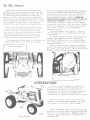
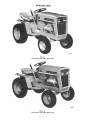
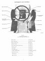
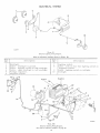
INTRODUCTION
International
Illust. 1
Cub Cadet 122 Tractor.
International
Illust. 1A
Cub Cadet 102 Tractor.
INTRODUCTION
{nternational
Illust. 2
Cub Cadet 71 Tractor.
De scription
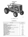
INTRODUC TION ..........................
CONTENTS
...............................
INSTRUMENTS
AND CONTROJ._ ................
BEFORE
OPERATING
YOUR NEW TRACTOR .......
OPERATING
THE ENGINE
...................
FUEL SYSTEM
...........................
DRIVING THE TRACTOR .....................
HITCHING
TRAILING
EQUIPMENT
TO THE TRACTOR
REAR POWER TAKE-OFF
...................
FRONT POWER TAKE-OFF
...................
ENGINE COOLING
AND AIR CLEANER
...........
ELEC TRICAL
SYSTEM ......................
FRONT WHEELS
..........................
PNEU 1ViATIC TIRES ........................
CLUTCH
AND BRAKE
......................
STORING
THE TRACTOR
....................
EXTRA EQUIPMENT
AND ACCESSORIES
.........
TROUBLE
SHOOTING .......................
LUBRIC ATION
...........................
LUBRICATION
TABLE ......................
LUBRICATION
GUIDE
......................
SPECIFICA
TIONS
.........................
INDEX .................................
Page
Inside
No.
cover,
Z
3, 4
1, Z
5, 6
6, 7
8, 9, I0
I0, II
IZ
13
14
14 to 19
ZO
ZO, Zl
21, 22, 23
24
24
25, 26
Z6, 27
27
28 to 32
32 to 34
35
Your
Cub
oughly
acquaint
befoxoe
attempting
Cadet
Tractor
yourself
to
start
has
with
a, ll
been
the
oz.- operate
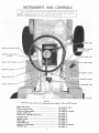
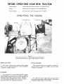
Illust.
Instruments
the
Thorcontrols
tractor,
3
and controls on the International
Brake pedal lock .........................
Choke control button .....................
Clutch and brake pedal .....................
Creeper shift lever ........................
Front power take-off clutch lever ..............
Gearshift lever ..........................
Ignition switch ..........................
Lift handle .............................
Lift handle stop ..........................
Lighting switch button .....................
Throttle lever ...........................
safety
engi_'_eered,
i_strurr_ents
and
Cub Cadet 71, 102, and 122 Tractors.
See pages 8 and 9.
See page 6.
See pages 21 and 22.
See page 9.
See page 13.
See page 9.
See page 14.
See page 11.
See page 11.
See pages 14 and 17.
See page 5.
iNSTRUMENTS AND CONTROLS
BEFORE OPERATING YOUR NEW TRACTOR
Lubrication
......
Tires
..........
Fuel
system
Lubricate
Check
.....
the
the
entire
air
pressure.
Fill the fuel tank
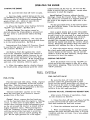
Illust.
Fuel
system
and controls
(international
Cub
Cadet
THROTTLE LEVER
This
When
set
a uniform
lever
controls
with
See pages
See pages
gasoline.
26 to 32.
20 and 21.
See page 6.
5
on International
71,
tractor.
Cub Cadet
102 and 122 Tractors
123 Tractor.
are similar.)
LIFTING THE HOOD
the
speed
of
in a given
position,
engine
speed.
it
will
the
engine.
maintain
hood
is arranged
and forward
to make
readily
accessible.
The
tractor
the engine
to swing
and
up
fuel tank
GOVERNOR
The governor
is set at the time the engine
is assembled
and should
not require
readjustment
unless
the governor
arm
is removed
or
loosened
from
the governor
shaft.
Consult
your
International
Harvester
dealer
if the
governor
does not function
properly.
the
it
To raise
hood
at
upward
the
the
and
hood,
rear,
forward
take
hold
of
pull
outward,
to
its
stop.
each
and
side
raise
of
OPERATING THE ENGINE
STARTING THE ENGINE
Be
sure
the
fuel
shut-off
valve
is
open.
Z. Pull the choke
control button all the way
out {see Illust.
3 or4). More
or less choking
may
be
necessary
due
grade
needed
of
fuel,
when
to
variations
in
temperature,
etc.
Little
or none
the
engine
is warm.
will
be
3. Place
the throttle lever halfway
"SLOW"
and "FAST".
See Illust.
3 or 4.
4.Electric
Starting: The
started
unless
the brake
the way
switch.
down
to
activate
International
Cub
Tractors:
Check
is in the neutral
Cadet
Cub
the
the
cannot
be
is pressed
safety
71,
all
starting
I02,
and
Igg
to see that the gearshift
position.
S,e illust.
3.
International
to see
that
"N"
position.
engine
pedal
between
Cadet
123
speed
control
See Illust. 4.
All Models:
Turn
wise to the "START"
lever
Tractor:
lever
is
Check
in
the
wait
a few
5. After the
brake
pedal
then
engine
starts,
and gradually
try
the
when
Manual Starting: (Tractors without electric
starting). Raise the tractor hood. The retractable starter is mounted
on a support plate at
the front of the engine at the right side of the
tractor.
l°ut the gearshift
lever in the neutral
position and lock the brake.
Turn
the key ignition
switch
clockwise.
Give
starter
or pull
A steady
Always
straight
hold on
slowly.
extended
5.
the ignition key clockposition
and release
it
minutes,
not use
except
a quick
steady
pull on the retractable
handle
to start
the engine.
Do not jerk,
it out to its very
end in a rough
manner.
pull will accomplish
just as much.
pull the handle
so the cord
is in a
line through
the guide.
Maintain
your
the handle
and allow
the cord
to return
Releasing
the handle
when the cable
is
will shorten
the life of the starter.
the
as soon as the engine
starts; however
do not
operate
the motor-generator
for more
than
30 seconds
at any one time.
If the engine
does
not start within this time,
turn the key "OFF"
and
control
button
all the way
in.
Do
choke
to enrich
the fuel
mixture,
necessary
to start
the engine.
After
necessary
engine
starts,
slowly
release
to
start
the
engine.
STOPPING THE ENGINE
Move
again.
slowly
release
push the choke
the
the
clutch
pedal
and
gradually
push
the
choke
control
button
all the way
in.
Do not use
the
choke
to enrich
the fuel
mixture,
except
when
sition
time
"OFF"
the
throttle
lever
and
allow
the
before
stopping.
position.
to
engine
Then
the
"SLOW"
po-
to idle
for
a short
turn
the key
to the
FUEL SHUT.OFF VALVE
FUEL SYSTEM
Be
Fill
the
fuel
grade
gasoline,
day's
laden
use.
air
tank.
with
clean,
preferably
at
fresh,
the
fuel
the
tank
filler
vent
open
flow
of the
cap
at all
fuel.
has
an
times
to
regular
end
This
will
force
out any
and
prevent
condensation
Do not mix oil with the gasoline.
The
Keep
proper
tank
of
each
moisturein the
air
fuel
vent.
Caution!
Never
remove
tank when
near an
til the
stop,
valve
seat
on
to prevent
is in its
shut-off
valve
the gasoline
needle
stem
the
stem
leakage
full-open
on
the
tank
is
(Shut-off
fuel
open.
valve)
un-
is
tight
against
the
or seepage
when
the
position.
CLEANING THE FUEL STRAINER AND SEDIMENT BOWL
assure
the fuel tank
the engine
open flame.
smoke
when
working
around
as the air around
the tractor
the
under
out the
he
or fill the fuel
is hot, or when
sure
strainer
Screw
cap
is running,
Do not
inflammable
fuel,
is mixed
with a
highly explosive
vapor.
When
pouring
fuel,
keep
the container
or hose nozzle
in contact
with the metal
of the fuel tank to avoid the
possibility
of an electric spark
igniting the
gas. Do not spill gasoline
on a hot engine.
After
fuel
every
strainer
Z5 hours
of
as follows:
operation,
clean
i. Close
the shut-off valve. See lllusts.7and 7A).
Loosen
the knurled
nut under
the sediment
bowl and remove
the bowl and screen.
Z.
Clean
the
sediment
bowl
and
screen.
3. When reassembling,
be sure
the gasket
between
the bowl and the main
body is in good
condition
and does not leak.
Use a new gasket
if necessary.
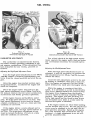
FUEL SYSTEM
Illust. 7
Carburetor and fuel strainer.
(International
Cub Cadet 71 Tractor)
Illust. 7A
Carburetor and fuel strainer.
(International
Cub Cadet 102, 122 and 123 Tractors)
CARBURETOR ADJU STMENTS
The
carburetor
is adjusted
For a final
ment,
operate
any corrections
tion.
at the factory
and under
normal
operating
conditions
it will
not require
readjusting.
If this adjustment
has
been disturbed
for any reason,
proceed
as
follows:
Adjusting
the High-Speed Adjustment
Adjusting the Idle Adjustment Screw
Screw
After
the high speed
adjustment
screw
is
adjusted,
it may be necessary
to readjust
the
idle adjustment screw (IIlusts.
7 and 7A),as each
affects the other.
Turn the high speed
adjustment
screw
(lllusts.
7 and 7A) counter-clockwise
approximately
two
turns from the closed position and start the engine.
After
the
engine
ating
temperature,
check
its
response.
has
reached
accelerate
normal
the
engine
check
of the high speed
adjustthe engine
under
load and make
necessary
for smooth
opera-
Close the idle adjustment
screw to its seat
by turning
it clockwise;
then open it one turn.
Start the engine and operate
it at fast idling
speed (without any load) until thoroughly
warm.
operand
While
the engine
is running
at fast idle
speed,
it is advisable
to screw
in the throttle
stop screw
([llusts.Tand
7A)a few turns
to keep
the engine from stopping when the throttle
lever is moved to the fully retarded "SLOW"
position. The engine will then be idling at a
fairly high speed and the throttle stop screw
can be backed out a littleat a time until the
desired idle speed is obtained.
Place the engine under load and turn the
high speed adjustment
screw (lllusts. 7 and 7A) to
the leanest
mixture
that will allow
satisfactory
acceleration
and steady
governor
operation.
If the engine misses
and backfires
under
load, the high speed mixture
is too lean.
The
high speed adjustment
screw must be turned
counter-clockwise
1/4 turn at a time until the
condition
is corrected.
If the engine
misses
or rolls
while
backing
out the throttle
stop screw,
the idle adjustment
screw
may be adjusted
in or out until
the engine operates
smoothly.
Speed
up the engine
for a few seconds;
then recheck
the idle adjustment.
A slight
adjustment
in or out will
give the smoothest
idle.
If the engine shows a sooty exhaust
and is
sluggish
under
load, the high speed mixture
is
too rich.
The high speed adjustment
screw
must be turned
clockwise
1/4 turn at a time
until the condition
is corrected.
7
PREPARING THE TRACTOR
Fill the fuel tank
run.
See page 6.
Check
the
at the
crankcase
oil if necessary.
Clean
the
See page 14.
FOR EACH DAY'S WORK
end
of each
oil level
and
day's
add
new
See page 26.
air cleaner
Inspect
the
pages 20 and 21.
tires
element
for
if necessary.
general
See
condition.
ADJUSTING THE SEAT
Illust. 8A
Adjusting the seat.
(International
Cub Cadet 102 Tractor.)
Illust. 8B
Adjusting the seat.
(International
Cub Cadet 71 Tractor.)
Illust. 8
Adjusting the seat.
(International Cub Cadet 122 and 123 Tractors)
Before
starting the tractor,
adjust the seat
to the most
comfortable
driving
position by
loosening
the four cap screws
in the seat support (Illust. 8) or seat bracket
(lllust.
SA) or seat
spring
clamping
plate
seat assembly
forward
(Illust. 8B) and
or rearward
position which
operator.
comfortable
Retighten
adjusted.
The
Tractors
forward
ience
rain
is most
the
cap
International
features
over
the
a
screws
sliding
to the
for
after
the
Cub
Cadet
122
and
which
can
be
steering
in adjusting
the
seat
and snow.
See |llust. 8.
wheel,
and
for
to
keep
the
seat
seat
the
is
123
tilted
convenout
Illust.
8C
Brake pedal lock in the engaged position.
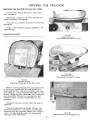
DRIVING THE TRACTOR
(InternationalCub Cadet 71, 102 and 122 Tractors)
CLUTCH AND BRAKE PEDAL
The combination
clutch and brake pedal is
used to disengage the engine from the transmission when shifting gears and to actuate the
brake to stop the tractor. The pedal must be
pressed all the way down to activate the safety
starting switch when starting the engine.
To disengage the clutch, press the pedal
approximately
half way down. To stop the tractor press the pedal all the way down.
Note:Do not rest your foot on the pedal
while driving the tractor, as this will result
in excessive clutch lining wear.
Always be sure
to turn. Under any
attempt
to free the
engine and suddenly
backing
out instead
the rear wheels
are free
adverse
conditions,
do not
tractor
by speeding
up the
engaging
the clutch.
Try
of going forward.
STOPPING THE TRACTOR
all
the
Disengage
the way
neutral
the
down.
position.
clutch
Move
by pressing
the
gearshift
the pedal
lever
to
LOCKING THE BRAKE
Always
lock the brake when the tractor is
parked on a grade. To lock the brake, press
down on the brake pedal; then place the brake
pedal lock in the engaged position. To disengage the lock, press down on the brake pedal
liftthe lock up and place it in the disengaged
position behind the brake pedal as shown
in
Illust. 17A.
GEARSHIFT LEVER
To operate
the tractor
in creeper
drive,
move the creeper
shift lever
(illust. 3) all the
way rearward.
Then select
the speed desired
and proceed
as instructed
under "Starting
the
Tractor".
The
following
able
in each
of
reverse
gear.
STARTING THE TRACTOR
the
The creeper
drive provides
a slower
speed
in each respective
gear,
by a four-to-one
reduction in speed from direct drive.
When the
creeper
shift lever is all the way forward,
it
is in direct drive,
or all the way rearward,
it
is in creeper
drive.
See Illust. 3. Note: Do not
use a mid-point
position
on the creeper
drive
as neutral.
Neutral
position
must be selected
only with the standard
transmission
gearshift
lever.
OPERATING THE CREEPER DRIVE
This lever
is used to select
various
gear
ratios
provided
in the transmission.
There
are three
forward
speeds
and one reverse
speed. See Illust. 3. Refer to "SPECIFICATIONS"
on page 32.
1. Advance
Illust. 3.
CREEPER SHIFT LEVER
throttle
lever
the
table
shows
the
three
forward
Miles
the
clutch
by
the way
down,
pressing
and
move
gearshift
to
speed.
lever
the
desired
the
the
Gear
3. Start
the tractor
in motion
by slowly
releasing
the clutch
pedal
and moving
the
throttle
lever
to the position
where
the engine
operates
best
for the load to be handled.
Note: Do not shift
clutch
is engaged
or
motion.
gears
while
while
the
the tractor
availand the
See
slightly.
Z. Disengage
clutch
pedal
all
speeds
gears
engine
is in
Per
Direct
Drive
Hour
Creeper
Drive
First
Z. 3
Second
3.9
1.0
Third
6.8
1.7
Reverse
Z. 5
.6
.6
DRIVING THE TRACTOR
(InternationalCub Cadet 123 Tractor)
BRAKE PEDAL
The
brake
way
down
When
the
tion
lever
it
Note:
pedal
must
to activate
brake
pedal
automatically
to the
"N"
q_e pressed
the
is
safety
in the
moves
position.
the
all
starting
depressed
speed
pedal
cause
the
switch.
posi-
"N"
Do
not
rest
your
foot on the brake
while driving
the tractor
as this would
the speed
control
lever to return
to the
position.
control
STARTING THE TRACTOR
The
pressing
the
speed
tractor
can
the
pedal
control
be
all
lever
stopped
either
by
the way
in the
down,
or placing
"N"
position.
I.
Illust.
LOCKING THE BRAKE
Advance
the throttle
lever
slightly.
See
4.
g. Depress
the brake
pedal by pressing
the
pedal all the way down,
and move
the towing
lever (Illust.
4) in drive (horizontal)
position,
then move
the throttle lever to the position
Always
lock the brake
when
dismounting
from
the tractor.
To lock the brake,
press
down
on the brake
pedal; then place the brake
pedal lock in the engaged
position.
See lllust.8C.
where
the engine
be handled.
To disengage
the lock, press
down
on the brake
pedal_
lift the lock up and place
it in the disengaged
position behind
the brake
pedal as
shown
inllIust.17A.
3. Start
operates
the tractor
the speed
control
lever
as de scribed
above.
best
for the
in motion
forward
load
to
by moving
or
rearward
RELEASE LEVER
SPEED CONTROL LEVER
This
lever
is used
to select
any
To push
or move
tractor
for
a short
distance
or when
working
on the
engine,
the
release
lever
(Illust. 4) must
be locked
in the
release
(down)
position
and
the speed
control
lever
must
be in the "N"
position.
Gaution:
Do Not
Tow.
speeds
from
a standstill "N" position to eight miles
per hour in the forward
direction
and to four
miles
per hour
in the reverse
direction.
STOPPING THE TRACTOR
Moving
the speed
control
lever forward
provides
increased
forward
speeds,
and moving the lever rearward
provides
the reversed
Move
the
speed
position
or use
always
depress
speeds.
control
the brake.
the brake
lever
Before
pedal.
to the
"N"
dismounting
TRAILING EQUIPMENT TO THE
the
bar.
must be
hole
in
Trailing-type
equipment
tractor
only at the hitch
Seelllusts.
11 and llA.
When
the
tractor
has
(lllusts.
11 and 11A) equipment
a three-point
adaptable
hitched
to
the draw-
to
three-point
hitch is raised
and lowered
with
the lift handle.
The lift handle
can be set to
hold the equipment
at various
positions
by use
of the six notches
in the lift handle
quadrant.
The lower
mounting
bracket
has three
holes
which
are used
for additional
adjustment.
hitch
the
10
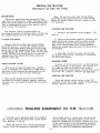
HITCHING TRAILING EQUIPMENT TO THE TRACTOR
Illust.
11A
Drawbar and three-point hitch.
(International Cub Cadet 102, 122 and 123 Tractors)
Illust.
Drawbar
11
and three-point
International
hitch
Cub Cadet
shown
on
71 Tractor.
LIFT HANDLE
Th.is
handle
ment
used
with
release
button
When
position,
operating
depress
is used
to lift
or lower
the tractor.
Depress
to move
the handle.
equipment
the
in
release
be limited
nut,
slide
and
tighten
Refer
hitching
the equipment
is
of the lift
handle
bail
allowed
forward
by the adjustable
stop.
the
stop
to the
required
the nut.
See Illust. 11B.
to the
equipment
instructions.
"FLOAT"
button
the handle
and
move
the wire
of the button.
See Illust. 11B.
When
position
the
manual
equipthe
on
over
top
of
the
top
to float,
the
travel
can
Loosen
position,
for
the
Illust.
proper
Adjustable
11
11B
stop limiting handle travel.
REAR POWER TAKE-OFF
(InternationalCub Cadet 71, 102 and 122 Tractors)
Illust.
Operating
International
If
your
tractor
is
12
Itlust.
the Power Take-off.
Cub Cadet 71 Tractor
equipped
power
take-off,
the following
precautions
should
be carefully
followed.
with
12A
Operating the Power Take-bff.
International Cub Cadet 102 and 122 Tractors
a rear
instructions
studied
and
and
The rear
power
take-off
is started
and
stopped
by the same
engine
clutch
as the
tractor.
Be sure
to disengage
the engine
clutch
before
moving
the power
take-off
shift
er rod (Illust. 12), or shifter
lever
(Illust. 12A).
The shifter
rod should
always
be in the disengaged
(forward)
position
and the shifter
lever
in the disengaged
(rearward)
position
when the power
take-off
is not in use.
4. On the International
Cub Cadet
71
Tractor;
Press
down on the shifter
rod
(Illust. 12) and move
it rearward
to the engaged
position.
Then
release
the shifter
rod and
allow
it to lock in place.
-
On
Tractors;
forward
the
International
move
to the
Cub
Cadet
the
shifter
le_er
engaged
position.
102
(Illust.
and
1ZZ
12A)
Caution! Always
cover
the power
take-off
exposed
shaft
with the guard
when the power
take-off
is not being
used.
5.
Slowly
release
the
clutch
pedal.
OPERATING THE REAR POWERTAKE-OFF
WITH THE TRACTOR STANDING STILL
OPERATING THE REAR POWER TAKE.OFF
WITH TRACTOR IN MOTION
1. The transmission
be in the neutral
position.
gearshift
2.
speed.
lever
the
Move
the
throttle
3. Depress
the
engine
clutch.
clutch
pedal
lever
back
must
to low
Follow
the first
four steps
outlined
above;
then engage
the power
take-off
shifter
rod or
lever.
Keep
your
foot pressed
down on the
clutch
pedal
(in the disengaged
position),
advance
the throttle
lever
and move
the
transmission
gear-shift
lever
to the speed
that
is desired
to run the tractor.
Slowly
release
the clutch
pedal.
This will start
the
tractor
in motion
with the power
take-off
in
operation.
idle
to disengage
IZ
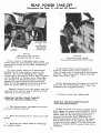
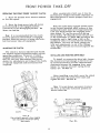
FRONT POWER
OPERATING
THE FRONT POWER TAKE-OFF
After considerable clutch use, it may be
necessary
to readjust the button clearance as
described below to assure proper clutch disengagement.
CLUTCH
i. Move the throttle lever back to medium
or low idle speed.
g.
lever
Move
the
(forward)
front
to the
(rearward)
to
the
Illusts.
3 or 4 and 13A.
power
take-off
engaged
position
disengaged
TAKEo, OFF
clutch
position.
With the clutch fully engaged
(clutch lever
in the forward
position)
place a piece of thin
cardboard
(match
book cover)
approximately
See
1/64 inch thick between
the engaging
lever
wear
button "A" and the pressure
spring
thrust button "B" (lllust.
13),loosen
the jam
nut
Note: It is recommended
that the clutch
lever be placed in the forward or engaged
position when the tractor is being used without front power take-off equipment.
on the turnbuckle
uCu (lllust.
13A), and adjust the
turnbuckle
until a light drag is felt on the
cardboard
when
it is removed
from
between
ADJUSTING THE CLUTCH
The clutch is factory adjusted and should
not require further adjustment under normal
operating conditions. However,
if clutch
slippage should occur.
It is recommended
that you see your International Harvester
dealer for satisfactory servicing of the clutch,
as special equipment
and instructions are
required.
the buttons.
Be sure
1/64 inch adjustment,
all slack, except
the
is out of the linkage.
Then,
tighten
turnbuckle.
nut
the jam
securely
against
the
INSTALLING AND REMOVING DRIVE BELT
To install or remove
the drive belt, loosen
the clutch lever bolt enough so the lever can
be moved forward to provide sufficient belt
clearance between the engaging lever wear
button "A" and the pressure
spring thrust
button "B".
See Illust. 13.
After installing a new belt, move the clutch
lever back onto the clutch lever latch and
tighten the bolt. See Illust. 13.
Note:
It is not
always
necessary
the lever in the fully horizontal
shown
in Illust.
13A.
Illust.
View
with
lever
grille
wear
removed
button
thrust
13
to show engaging
and pressure
button.
spring
Illust.
13
13 A
to place
position
as
ENGINE
AND
AIR CLEANER
ENGINE COOLING
This
tractor
has an air cooled
engine.
Air
must
be able to circulate
freely
around
the
engine,
through
the screen
and shroud,
and
over
the fins of the cylinder
head and cylinder
block.
Keep these
areas
free of accumulated
dirt
and trash
or the engine
will overheat
and
result
in damaged
moving
parts.
......
....
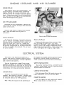
DRY-TYPE AIR CLEANER
Incoming
air for combustion
a dry-type
air cleaner
having
inside
of the cover.
Remove
and
with
a new
noticeable.
clean
one
or
when
is filtered
by
a filter
element
replace
loss
of
the
power
element
is
Illust. 14
Removing the air cleaner filter element.
Cleaning the Element
To
and air
element
cause
paper
Do not
as this
or use
The
tractor
pally
and
Replacing the Element
clean
the element,
remove
the wing nut
cleaner
cover
(Illust. 14) then
remove
the
and tap it lightly
on a flat surface
to
the loose
dirt to fall off.
Handle
the
element
with care
to avoid
perforations.
use compressed
air to remove
the dirt
can rupture
the element.
Do not wash
a solvent.
twelve-volt
with
electric
electrical
starting
system
consists
of a motor-generator,
a twelve-volt
battery.
Use
the
diagrams
the various
electrical
illustrations
17 and
are
clean
and
securely
the
and
Turn
a new
one
if dirt
tighten
the
wing
nut
finger
tight.
The
clutch
the
all
ing
fastened.
safety
or brake
the
engine
starting
pedal,
switch,
serves
activated
to prevent
by the
start-
accidentally.
SWITCH BUTTON
SWITCH
clockwise
to
ignition.
With
electric
actuates
the motor-generator.
be removed
when
in the
starting,
Note:
with
SAFETY STARTING SWITCH
wiring
LIGHTING
IGNITION
element
the engine
has
stalled
and the operator
leaves
the tractor,
the key must
be turned
to the
"OFF"
position
to prevent
battery
discharge.
regulator,
on page 18, as a guide
for
identifying
electrical
units
and
for
tracing
cables
and connections.
Be sure
connections
cover
on a
princi-
voltage
on page
Replace
does
not drop
off easily
or if it is bent,
crushed
or damaged.
When
replacing
the
element
be sure
it fits
snugly
around
the inside
edge
of the
air
cleaner
base.
Then
replace
the
the
When
key
the
engine
turn
not
Pull
the button
(Illust. 17A) out to turn
on
lights
and push it in to turn
off the lights.
the
a further
The
key
position.
"ON"
is
on
operating
turn
cannot
CIGARETTE
the
LIGHTER
Push the lighter to make electrical contact.
When it pops back it is ready for use.
or
14
ELECTRICAL SYSTEM
SPARK PLUG
IGNITION TIMING
Note: Remove
spark
plug before
all dirt from
the base of the
removing
the spark plug.
Remove
the spark plug after every i00
hours of operation for cleaning and checking
the gap. See lllust.
15.When making this adjustment, always bend the outer electrode. Never
bend the center electrode, as it may damage
the insulator. If the gap between the electrodes
is too great, the engine will misfire and be
hard to start.
Illust.
Always
moving
use
or
a spark
reinstalling
plug
the
wrench
when
re-
Adjusting
plug.
the
15A
breaker
points.
Set gap at .020-inch.
Be sure
the gasket
is in good condition,
and screw
the plug in tightly.
Do not tighten
more
than
enough
to compress
the gasket
to
seal the plug and assure
a good heat transfer
between
the plug and the cylinder
head.
Tighten
the plug 1/Z to 3/4 turns
past
finger
tight.
Remove
the breaker
point
cover
after
every
100 hours
of operation
for cleaning
the points
and resetting
the gap (illust. 15A). Replace
badly
pitted
or burned
points.
For more
precise
timing,
a timing light
should
be used.
The engine
has a timing
sight
hole which
is located
in the right
side of the
engine
bearing
plate
on the International
Cub
Cadet
71 Tractor
or in the right
side of the
blower
housing
in the International
Cub Cadet
10Z,
lZZ and lZ3 Tractors.
Seelllusto15B.
With the engine
running
at 1/3 throttle,
or
more,
adjust
the breaker
points
until
the "SP"
mark
on the flywheel
is centered
in the sight
hole.
Note: The "SP"
mark
will appear
Z0
degrees
before
top dead center.
The other
mark
is the top center
mark
and is stamped
with "DC"
below
the mark.
Illust. 15
Checking the spark plug gap.
Set gap at .025-inch.
See
Replace
your
correct
a defective
International
replacement
plug
with
Harvester
a new
dealer
plug.
for
a
plug.
Cleaning the Spark Plug
Sandblasting
is
the
recommended
method
of
cleaning
the
spark
plug.
Never
scrape
or clean
the
insulator
with
anything
which
will
scratch
the porcelain.
Scratched
porcelain
allows
carbon
and
dirt
to accumulate
much
faster.
Illust.
location
(Motor-generator
illustrate
15
15B
of timing sight hole.
has been removed to better
the location).
ELECTRICAL SYSTEM
MOTOR-GENERATOR
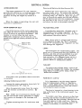
Removing and Replacing the Motor-Generator Belt
The motor-generator
(12-volt,
negative
ground)
will function as a cranking
motor when
the ignition
key is turned to the "START"
position,
driving
the engine by means
of a
belt.
When
function
the engine
is
as a generator.
operating,
the
unit
Replace
the motor-generator
belt when it
becomes
badly
worn.
To remove
the old belt,
loosen
the motor-generator
brace
bolt "A" and
mounting
bolts
"B",
Illust. 17. Move
the generator
in toward
the engine
and slip the old belt
off the pulleys
and over
the crankshaft.
Install
the new belt in the reverse
order
of removal
and adjust
the belt to the proper
tension.
will
BELT
MOTOR-GENERATOR
VOLTAGE
Check the tension
of the motor-generator
belt after the first
10 hours of operation
and
every 50 hours
of operation
thereafter.
The
tension
is correct
when the belt can be
deflected
a maximum
of 1/4-inch
by a ten
pound force applied
midway between
the two
pulleys.
REGULATOR
A satisfactory
generator
charging
maintained
by the voltage
regulator.
regulator
fails to operate
correctly,
International
Harvester
dealer.
rate is
If the
see your
Note: Never place a jumper
lead between,
or accidentally
bridge,
the "BAT" terminal
and the "F" terminal
on the regulator,
as this
will damage the regulator.
Affow _/_ inch
LIGHTS
The headlights
are
parts
are
so constructed
flector,
and lens
are
permanently
and
corrosion.
sealed-beam
that
the
all assembled
sealed
against
If a filament
lights.
The
filament,
rein a unit
dirt,
moisture,
burns
out or
lens
breaks,
the complete
unit
must
placed.
Refer
to "SPECIFICATIONS".
be
a
re-
TAILLIGHT
II_
Correc_
Also follow
is installed.
_6
motor*generator
this
To replace
the taillight
lamp,
lens
from
the taillight
and replace
lamp with a 4 candle
power
lamp.
"SPECIFICATIONS".
be_ )e_iQ_.
procedure
when
a new
belt
FUSE (Electric Lighting)
Adjusting the Motor-Generator Belt
It
Loosen
the motor-generator
brace
mounting
bolts
"B",
Illust. 17.
bolt
and
until
Move
the
engine
See
Illust.
the
generator
tension
on
the
away
belt
from
the
is correct,
"A"
bolts
"B"
and
brace
important
to
use
the
same
capacity
a
The fuse is located in a fuse housing in the
!ine at the back of the instrument panel. See
Illust. 18.
Note: Under
no circumstances
should
a pry
bar.be
used
on the motor-generator
to obtain
belt tension
as damage
to the bearings
will
r e sult.
mounting
is
fuse
for replacement.
Refer
to "Specifications".
If the lights
fail,
check
the fuse.
If
fuse
continually
burns
out,
check
the electrical wiring
for
short
circuits.
16.
Tighten
remove
the
the taillight
Refer
to
To
install
a new
fuse,
press
in
on
the
fuse
housing
cap
and
turn
counterclockwise
to remove
it from
the
fuse
housing.
Remove
the old
fuse
and replace
it with
a new
one.
Then
re-
bolt
assemble
battery
flAIl
16
if
the cap
necessary
to
the housing.
to reach
the
Remove
fuse.
the
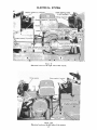
ELECTRICAL SYSTEM
Illust.
Electrical
Electrical
17
units on the right side of the tractor.
Illust. 17A
units on the left side of the tractor.
17
[LECTR!<AL
SYSTEM
2
3
10
5
+H+s+. 18
++++t+im+igh++++w++++n9
+++gr+m+
[_ex 1+ +++++++++
+umb++s sh++,+ +++H+s++18+
De i_c =[p[ion
I
2
5
L gh_ing s_ itch+
m a
_ _;ic s w[ _oh+
C Ms_ e + ightin_;
S++_+,
tch
'r+_l
-+++ }++t
+ +
4
5
6
++++s++
18A
S++ +++++++ ++{+,+m¢+_
n+m_+++ ++ p+g+ +%
i8
8c
£HSh_+
ELECTRICAL SYSTEM
Index to reference numbers shown in Illust.
RofI
De s c ription
Key
ignition
switch.
'.Cable
- ignition
coil
to key
black.
ignition
positive
switch
18.
(+)
"IGN"
terminal
terminal
No.
I
10
11
!Voltage
ICable
1Z
! generator
"A" terminal
!Cable
- regulator
"F"
• generator
"i_'' terminal
_Cable
- voltage
regulator
- yellow.
lower
mounting
rrpink.
ground
-
Description
regulator.
- regulator
"GEN"
3
Cable
13
4
5
switch
"BAT"
terminal
- light green:
Safety
starting switch.
Cable
- safety starting
switch
to key
ignition switch
"ST"
terminal
-
14
iCable
orange.
Cable
- safety starting
switch
to
magnetic
switchorange
w/black
tracer.
15
16
MotorBattery.
17
Magnetic
switch.
Cable
- generator
magnetic
switchCable
- regulator
18
Cable
- battery
positive
magnetic
switch.
Cable
- battery
negative
19
Z0
ground.
iBattery terminal
ilgnition coil.
Z1
[Condenser.
7
8
9
- magnetic
magnetic
switch
to key
ignition
"A" terminal
red.
"BAT"
terminal
switch-
to
to
gray.
STORAGE BATTERY
adds
use
Battery and Cables
cal
See
all
When
replacing
a battery,
being
frayed
make
to prevent
shorting
Caution!
against
receiving
Caution!
filler caps
(-) terminal
to
cover.
battery
fully
but makes
it
charged
available
not
only
for
instant
battery
at least
once
a month
for
Electric
storage
batteries
added
no
"dopes,
give
a steady
off
Do
charge.
not under
any
circumstances
terminals
as this may
result in a spark
or
short circuit which
may
cause
an explosion.
Be careful
to avoid spilling any electrolyte
light coat of vaseline
or chassis
lubricant.
Be
sure the terminals
are clamped
tightly and
that the battery
is fastened
securely
in the battery box. Replace
unserviceable
cable.
Keep
in the battery
to
allow an electric spark
or an open flame
near
the battery.
Do not lay tools across
battery
Occasionally
remove
the battery
cables
and
brighten
the terminal
contact
surfaces
with
wire wool,
and reassemble
them.
Apply
a
holes
Keeping
the
to its life
when
needed.
(+) terminal
highly inflammable
hydrogen
gas when
charging and continue
to do so for some
time after
Cleaning and Servicing the Battery
the vent
generator.
Acid or electrolyte
should
never
be
except
by a skilled battery man.
Under
circumstances
add any special
battery
solutions
or powders.
the
ground
cable is connected
to the negative
(-)
terminal
on the battery.
Be sure the rubber
boot is properly
positioned
over the positive
(+) terminal
on the battery.
Note: Both cables
must
be assembled
with the nuts to the inside
of the terminals
the pedestal.
-
The electrolyte
(acid
and water)
in each
cell
should
be at ring
level
at all times
to prevent battery
failure.
When the electrolyte
is
below
this level,
add pure,
distilled
water.
by
certain
bolt to battery
harness.
Check
the
water
level.
work
has been
completed.
This will prevent
shorting
and damage
to any of the electrical
units. Examine
the electrical
cables
occasionally to be sure they are not
contact
with adjacent
parts.
to
blue.
to
Liquid Level
Before
working
on any part of the electrisystem,
disconnect
the battery
ground
cable at the battery
negative
(-) terminal.
lllust.17. Do not reconnect
this cable until
terminal
- light
terminal
on hands
or
clothing.
For
dependable
battery
International
Harvester
open.
19
service,
dealer.
see
your
"
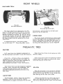
FRONT WHEEL TOE-IN
Illust. 20
Front wheel adjustments.
Illust. 20A
Tie rod and drag llnk ball joints.
The front wheel
toe-in
dimension
is 1-32inch to 1/8-inch
toe-in
(1/3Z-inch
to 1/8-inch
closer
in front than in the rear).
Measure
the
distance
between
two points
"A" and two points
"B" Illust.
20. Points "A" and "B" must be on the
inside
of the wheels
at the outer
edges
and at
the same
height
from
the ground
as the front
wheel
hubs.
tie
To adjust
rod
ball
the
joint
toe-in,
"C"
the
lock
end
in
nut,
or
out
and
as
turn
the
tie
rod
ball
joint
required.
TURNING RADIUS
for
The
left
front
and
wheels
should
have
an
right
turns.
If adjustment
equal
is
angle
nec-
essary,
disconnect
the drag link ball joint "D"
(lllusts.
20 and 20A) loosen
the lock nuts and turn
the drag link ball joint in or out as required.
disconnect
either
(lllusts.
20 and 20A) loosen
REAR TIRES
6-12 rear tires are standard
equipment
on
the International
Cub Cadet
71 and 10Z Tractors.
Keep
destroy
Z3 x 8.50 - IZ Terra-Tires
are standard
equipment
on the International Cub Cadet I_Z
and IZ3 Tractors.
They are also available as
extra equipment when ordered for the
International Cub Cadet 71 and I07 Tractors.
After
using
the tractor
control
work--use
water
icals
that may be on the
The Terra-Tires
provide
maximum
mobility
in sand,
snow,
and soft
soil conditions.
The
reduced
ground
pressure
and low inflation
provides
maximum
protection
for turf,
soil,
and crops.
tires free
rubber.
from
oil and
grease
as both
for spraying--insect
to remove
any chemtires.
INFLATION
Keep
the
Underinflation
and may
also
thus
tea'ring
pneumatic
will
cause
out
the
tires
damage
the tire
tube
properly
the
to
valve
tire
slip
inflated.
cord
body
on the rim,
stem.
CARE OF TIRES
Avoid
hazards.
immediately
stumps,
Cuts
as
in
stones,
deep
ruts
and
tires
should
be repaird
neglect
decreases
the
tire
other
place
loss
life.
Z0
Always
see
that
the tire
and
tightened
securely
of air and
protect
the
valve
caps
to prevent
valve
core
are
in
the
and
stem.
PNEUMATIC TIRES
REAR WHEEL WEIGHTS
OPERATING PRESSUREFOR TIRES
or
Inflate
the
heavy
load
lowing
front
and
rear
operations
as
tires
for
shown
in
Rear
normal
the
table.
Load
Front
Tires
4o 00-8
16 x 6_ 50-8
Rear Tires
6_IZ
23x 8_50_1Z
Heavy
square
8
of
If additional
weights
can
by
using
inch
i0
6
increase
traction
and
weigh
are
bolts,
two
weight
is
be attached
longer
desired,
to each
a second
set
first
weight
bolts.
8
6
6
6
TIRE CHAINS
After mounting
a new
or old tire on the
rim, inflate it to ZO pounds
pressure
to seat
the tire bead on the rim flange and to prevent
ope rating
weights
Load
MOUNTING TIRES ON THE RIM
the tire from
valve.
Then
wheel
reduce
wheel
slippage.
The weights
approximately
Z6 pounds
each.
They
attached
to each
rear
wheel
with
two
lock
washers,
and hex.
nuts.
fol-
Tire
chains
will provide
additional
traction
for wet ground
conditions,
when
plowing
snow,
or pulling heavy
loads.
Rear
wheel
weights
are recommended
when
using
chains.
creeping
and shearing
off the
deflate the tire to the correct
pre s sure.
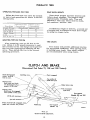
CLUTCH AND BRAKE
(International Cub Cadet 71, 102 and 122 Tractors)
Clutch disengaged:
tractor must be
free to coast.
Clutching zone,
Ff_
%
..............C utch engaged
Top surface of
pedal foot pad
Neutral zone:
Both brake and clutch
are disengaged when
pedal is in this zone.
return stop
movement
Braking zone:
Brake must be engaged
when pedal is in this zone.
(3/16-1nch)
Foot support
(Models 102 and 122)
1- 5/16-inch
3/4-inch
minimum
Brake must be fully engaged
pedal arm reaches this position.
/
Foot support
Pedal stop
(Model
Illust. 21
Clutch and brake adjustments.
Zl
71)
_J
A-84133
CLUTCH AND BRAKE
(InternationalCub Cadet 71, 102 and 122 Tractors)
As the clutch
and brake
are both operated
by the same
pedal,
care must
be taken to
maintain
a neutral
zone so the clutch
is disengaged
when the brake
is applied.
ADJUSTING THE CLUTCH
It
inch
is
be
important
maintained
lever
and
to maintain
have
inch.
the
this
that
a clearance
between
the
clutch
release
clearance,
a free
movement
See Illust. 21. This
at the
point
of
the
front
edge
contact
of the
of
clutch
. 050release
bearing.
the pedal
In order
should
of approximately
measurement
of the pedal
pedal
return
3/16taken
is
arm
stop.
with
The
clutch
pedal
adjustments
are
set at the
factory
and
should
not require
frequent
attention
unless
the
linkage
has
been
disturbed
or
when
the pedal
movement
becomes
less
than
3/16-inch.
When
it is necessary
to adjust
the
clutch,
release
turn
rod
get
proper
the
the
adjusting
(Illust. 22) in
or
nut
out
"A"
on the
as required
clutch
to
measurements.
ADJUSTING THE BRAKE
The brake
should
engage
when the pedal
arm is pressed
down to within
a maximum
of
l-5/16-inches
and a minimum
of 3/4-inch distance above the top of the left foot support,
which serves as the pedal stop. See Illust.
21.
way
It may
down
be possible
to the
pedal
to push
the pedal
stop,
but this
is
concern
as long
as the brake
is
the pedal
arm
is at least
3/4-inch
pedal
stop.
"B"
To adjust
and
turn
the
the
brake,
brake
all the
of no
engaged
above
loosen
the
lever
adjusting
jam
when
the
nut
screw
Illust. 22
"C"
(Illust.
22) in or out as required
to get this
measurement.
The brake
must
not engage
before
the pedal
arm
is within
the maximum
distance
of
1-5/16-inches
above
the
pedal
Clutch and brake adjustments.
stop.
ZZ
BRAKE
(InternationalCub Cadet 123 Tractor)
Speed control lever centering
zone when brake pedal is
Top surfaceof
pedal foot pad
Pedal return stop
Speed control lever is
in "N" position
Braking zone:
Brake must be engaged
when pedal is in this zone.
Foot support
1- 5/16-inch
maxim1
3/4-inch
minimum
Brake must be fully
pedal
arm
engaged
when//
l
reaches this position.
Pedal stop
A-86719
Illust. 23
Brake adjustments.
ADJUSTING THE BRAKE
The
brake
arm
is pressed
1-5/16-inches
tance
which
above
serves
It
way
may
down
If
should
engage
when
the pedal
down
to within
a maximum
and
a minimum
of 3/4-inch
the
top of the
as the
pedal
be possible
to the
pedal
concern
as long
as the brake
is
the
pedal
arm
J s at least
3/4-inch
pedal
stop.
To
adjust
the
brake,
of
1-5/16-inches
If
loosen
engaged
above
the
jam
above
the
see
this
your
wheel
turns
connecting
the jam
adjustment
International
nut
in
the
reverse
rod
"E"
"D".
does
not
Harvester
stop
when
the
nut
pedal
"B"
"C"
stop.
ADJUSTING THE SPEED CONTROL LEVER
Note: The brake
pedal
must
be properly
adjusted
before
beginning
the speed
control
lever
adjustment.
If the tractor
"creeps"
in the "N"
position
or,
if the speed
control
linkage
has
been disassembled
or removed
for any reason,
the following
adjustment
must
be made.
Block
the tractor
so the left rear
wheel
is
off the ground.
Start
the engine
at half throttle
or faster.
Move
the speed
control
lever
to the forward
position.
The rear
wheel
should
rotate
in the
forward
direction.
Depress
the brake
pedal
all
the way down and release.
The speed
control
lever
should
return
to the "N" position
and the
rear wheel
stop turning.
If the rear
wheel
turns
in the forward
direction,
loosen
jam nut "D" and turn
the connecting rod
_'E" counterclockwise
to lengthen
it
until
the wheel
stops
turning.
(See Illust. 23A).
Illust.
23A
Brake adjustments.
23
direction
clockwise.
all the
of no
and
turn
the brake
lever
adjusting
screw
(Illust. 23A)in
or out as required
to get this
measurement.
The
brake
must
not engage
before
the pedal
arm
is within
the maximum
distance
of
dis-
left
foot
support,
stop.
See Illust. 23.
to push
the pedal
stop,
but this
is
the
turn
the
Tighten
"creeping"
dealer.
A
STORAGE
Store your tractor in a dry and protected
place. Leaving your tractor outdoors, exposed to the elements, will result in materially shortening its life.
When
storing the tractor:
I. Wash or clean and completely lubricate
the tractor. See the "Lubrication Guide"
on
pages 28 to 32.
battery
at least once a month
for water
and amount
of charge.
See page 19.
6. On the International
Cub Cadet
71,
10g
and 122 Tractors
press
the clutch
and brake
pedal
all the way down and engage
the brake
pedal
lock.
This will prevent
the clutch
lining
from
sticking
to the pressure
plate.
7.
On
the
Tractors,
2.
until
Drain
the
the fuel
is
fuel
tank
exhausted
tem.
Clean
the
bowl. See page 6.
fuel
and
run the engine
from
the fuel
sys-
strainer
screen
and
glass
down
and
3. After
the engine
has cooled,
remove
the
spark
plug and pour
one table spoonful
of lubricating oil of good quality into the cylinder.
Clean
the
exterior
of
the
engine.
5. Remove
the battery and place it in a cool,
dry place above freezing (+3Z'F.). Check the
Cub
Cadet
123
the
brake
pedal
all
engage
the
brake
pedal
lock.
Fill
the
fuel
the
way
tank.
Z. Install
a fully
charged
sure
the proper
connections
Illusts.
17 and 17A.
battery
and
are
made.
be
See
3. Start the engine and let it run slowly.
Do not accelerate the engine rapidly, or operate it at high speed immediately
after starting.
Crank
the engine
slowly
turning
the generator
belt by hand to distribute
the oil over the cylinder walls.
Then
replace
the spark
plug.
4.
International
press
REMOVING FROM STORAGE
1.
Note: Gum will eventually
form
in the fuel
tank,
line,
and carburetor
if the unit is not
drained.
Gum can be dissolved
with acetone
or a 50-50
mixutre
of alcohol
and benzol.
level
Caution!
Keep
the doors
wide
open
or move
the machine
outside
the storage
room
diately, to avoid danger
from
exhaust
4.
Inflate
pressures.
and 21.
5.
Release
the
See
tires
to
"Pneumatic
the
brake
the
correct
Tires"
pedal
immegas.
operating
on pages 20
lock.
AND
The
types
under
tractor
of work
so many
is used
for
so many
and
is called
on top
different
conditions
riety
of equipment
is available
the
requirements
of the user.
When
you
purchased
your
probably
had
it
completely
to
tractor,
equipped
Type
to
different
operate
that
a va-
adapt
it to
you
for
particular
needs
at the time.
you
may
wish
to obtain
some
or accessories
shown
below.
other
allied
and
installed
de ale r.
equipment
by,
your
However,
later
of the
equipment
These
items
and
can
be purchased
from,
International
Harvester
your
of Equipment
Models
71
Cigarette Lighter ........................................
Charge Indicator ........................................
Creeper
Drive (International Cub Cadet 71, 10Z and 122 Tractors) .......
Detachable
Seat Pad ......................................
Dual Rear Wheels
.......................................
Electric Lighting ........................................
Hydraulic Lift ..........................................
Helper Spring ..........................................
Rear Power
Take-Off (International Cub Cadet 71, 10g, and 122 Tractors}..
Rear Wheel Fenders ......................................
Rear Wheel Weights ......................................
Three-Point
Hitch .......................................
Utility Box
..........................................
24
x
x
x
x
x
x
x
x
x
x
x
x
i x
used
10Z
122
on
123
X
X
X
X
X
X
X
X
X
X
X
X
X
X
X
X
X
X
X
X
X
X
X
X
X
X
X
X
X
X
Ix
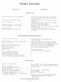
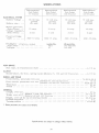
HARD TO START
H,> gaso
h+e
£n :_:_{eI tA:rli
Fu_:I
str_>_er or
Water
in gasoih_e
fuel
o:r c_F
uz_+t+u
t;logg_d
line
............
.....................
Ch+ked
:_+++prope+£y+
Fiooded
engf++e
.........
Defec+< v<+ £gmtiem
+r foes+
wir_mg
.........
De_ec{iVe
S + _ phg
+p++k
ba{_e
ry
dir+y
C_:eck and
.............................
o+
insprop<++
g_p
Cle+++,
............
se+rvh:+;
_dj++:st
s++ +m++i% or _eplact++
_b.i+ g+mp to
+@Z5 in+h,
or
++_a+::e
the pb_g
£NGIHE OPERATES
Er_g: i n+e :i+:+{::'
o r r e c tly
IRR£GULARLY
OR KNOCKS
ti n++
ed ...................
Sp++rk ?_ug d :++y; w _'+Jng gap o+ w veng type .....
P<++}
r o+' ,+re÷_ s?_+k
........................
Ca buretor
seSt£ng incorrect
.........
F+oo_' g:rs_s £¢el <H wate_
£s fse£ ...........
++gir_+
oveN+ca+ h_g .....................
£++g_me valve+
at f+a:uJt ......................
£:+_gi:ne ++++o_e s .........................
%
LACK, OF POW£R
E++%inu
C+M
or
++}++_
rh,aa+t:d
...............
E ng,i_+ overloaded
......................
Governor
n+t work£ng
p,--operly
+ + ..........
Poo+ c+>+_p++ssi+n ......................
Poor £:u++i or fee :lea+ a rmixtm+e ..............
Fuel
_e,
o_ s_r&ine_
@bstyu¢%ed
..........
F+4++ +a++A air v+a_ 61o+ed ...................
A++r clemme+
d, egged
O+ ai+ _+mkage
+e+v++em
carburetor
amd eagis_:
..............
See
++6+:++++buze'_+r
Clea:a}
<++_+n
°+ ++ p++++ + +_d 7+
+++ p+++ ++
t+:'+,e
veto+
¢S:1+A+__he air
Figh_ n t_e
_=
t:h8
Cap+
ete_ner
as
¢arbur_o:r
+ g+++y+++1+P+m++i++++
H++++++++
d+m++t+
in_gr:U,C+ed
+m pro++14+
a_d _,anii'old
TROUBLE SHOOTING
Possible Remedy
Possible Cause
LACK OF: POWER - Continued
See "Breaker
Points and Spark Plug" on pages
15 and 16.
Adjust the free travel of the pedal; seepages21
and 22.
Adjust
the brake;
see pages 21 and22.
Incorrect timing or faultyignition.........
Clutch slipping(Models 71, 10Z and 122) ....
Brake drags .......................
ENGINE OVERHEATS
Insufficient
cool air, dirty air intake screen,
shroud,
or cooling
fins ...............
Keep
the air
See "Engine
on page 14.
intake area and cooling
fins
Cooling
and Air Cleaner"
clean;
CREEPING
Speed control lever out of adjustment(Model
;',"
IZ3) See "Speed Control Lever Adjustment" onpoge23.
See your International
Harvester
dealer.
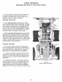
ENGINE OIL
The tractor
with SAE-10W
is shipped
from
the factory
engine
oil in the crankcase.
If
the engine
is to be operated
at temperatures
between
+75 degrees
F and 0 degrees
F, this
oil can be used for the first five hours
of
operation.
this range,
and replace
If the temperatures
are not within
drain the oii from
the crankcase
it with new oil as specified
in the
"Lubrication
Table".
The engine
oil must
be
drained
and replaced
with new oil every
30
hours
of engine
operation
thereafter.
Oils designated
recommended
for
"For
Service
this engine.
MS"
are
To aid starting, the selection of crankcase
lubricating oils should be based on the lowest
anticipated temperature
until the next drain
period.
Check
the oil levels
of the engine
crankcase
and transmission
to see that they are
filled
to the correct
levels.
Note:
Check
the
oil level
only while
the engine
is stopped.
Illust.
Oil
Z6
level
26
gauge.
The
crankcase
oil
filler
cap
_s_
_L_W _ mar_
Erie oil
level.
wiped
clean_
withdr;_wn
an the gauge,
When
checking
Lhe gauge
rn_t
b_ withdrawn
Enen
inserted
at_ the
way
_md
_or
,_ _ru_
-[RANSNJSSIONOiL F|LT'ER
Lh_o: oi_
g_uge
a.tt_.ched
to lto g_,e HJ_,w_ 26, Alway_
th_ _i_ level
between
LtH uF'ULL
_ and
level
keep
Lhe
_c,move
fhe
throw_w_w
(_H_t_ 23A)
_nd
replace
the firs_
10 no_rs
and
and
_tion,
after.
reading.
and
ever},
!0{1
ca_-type
with
_i[_r
na_ars
filter
a _ew [:Liter
50 nrmrs
_f
after
oper
__f _per.a_l<_n
[here-
go met'mow: [h_,z
fil%e_'or_rn [he fil%{_r[;ou_terclo<kwise us}r)_ ,{_amto;_,_,_tive
_pe fil_e_
_
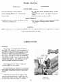
Before
Keep
yot4r
[ut_[y
lean
stappiy
;'lnd
;}f lub_icagi_
free
fre;rn
_il
dust
aR:_#_-
Alw;sy_
_n.stral[{a_
[he lubrication
£ubricato:r,
filter,
apply
_
Thread
[o [ea_
_l'_e
the
ga_._et.
_
en
Loo_
an<[ vcxpe
J_r[
{_@_n
before
app_.y_ng
the
_h_ m_w
eoadng
of oil on the filter
_eL
litter _.m by h_knd t_,nfiltight enough
[_sket
u_e
nta, ct_
_.dditioaa]
three
[k_{n_s
_
f_Rer_
Then
turn
it
u_ti!
_1_
the base.
Fighten
[h,e filter _r_
quarter
[urn, Check for leaks,
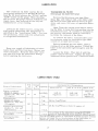
LUBR]:C,A JON TABL£
:?H_
Poi_st
of Lubri<a_
I
on
H
Engine c_
_kc_:_
s
_Z3, sn_nes
[ Z Z eng_.ne s
/180
C, reeper
drive
tsousin_
Models
7[, _OZ, an<{
1ZZ '}h'a¢ _ors
S _:_:e:rn
ear
i_eU
Ste_£n,g
knuc kff_:_s
AN r_e de 1_
£ng
1.0
gru-as'
and :_app[y'
[wo or
auff:[<b:,_t grc, s<÷ tof_'_s_'
Z?
_h_ere strokes
a_ the;
_,lubsj, cator
o<_[old grease and d _[.
0r
,S
f
--@i
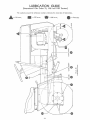
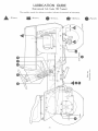
LUBRICATION GUIDE
(InternationalCub Cadet 71, 102 and 122 Tractors)
- - After Every 10 Hours of Operation
Check the oil (with the engine stopped) and add sufficient
new oil to bring it to the "FULL"
mark on the gauge. Do
not overfill. Do not operate the engine if the oil level is
below the "LOW"
mark on the gauge.
1 - Oil filler cap and bayonet-type
oil level gauge.
2- Steering knuckles (2).
3- Front axle pivot pin.
I
lithium
grease
apply or
sufficient
grease
to flush out old
Use IH-Z51
HEP and
grease
equivalent
#2 multi-purpose
grease and dirt.
After Every 30 Hours of Operation
While the oil is warm, remove the drain plug (4)and drain
allof the oil from the crankcase. Replace the drain plug.
Remove the crankcase oilfillercap (I).Refillthe crankcase with new oilup to the "FULL"
mark on the oillevel
gauge. Refer to the "Lubrication Table" for the proper
quantityand viscosityto use.
- Engine crankcase.
After Every 100 Hours of Operation
Use IH-Z51 HEP grease or equivalent #Z multi-purpose
lithium grease and apply two or three strokes of the lubricator to the lubricationfittings.
S-Power take-off shaft bearing
O
--Periodic
Check the oillevel periodically.Keep the lubricantup to
the level plug (6)on the rear of the transmission case.
Change the oilin the transmission case at least once a
year. Remove the drain plug (7)and remove the oillevel
and fillerplug (6)and allow allof the oilto drain out. Replace the drain plug. Refillwith approved lubricant up to
the level plug opening and replace the plug.
Transmission
6- Oil level and filler plug.
7- Oil drain plug.
Check
Creeper drive housing
8 - L.eveI pl ug.
9. Breather and filler plug.
10. Drain plug.
I
_
I
L
the oil level periodically.
Keep
the lubricant up to
the
level plug
on refill
the left
of the
creeper
housing.
Drain (8)
and
theside
housing
each
time drive
the oil is
changed in the transmission
case. To change the oil, remove the drain plug(10) at the bottom of the housing and
allow all the oil to drain. Then replace the drain plug.
Remove
the breather and oil filler plug (9) at the right
of the creeper shift handle on top of the frame assembly,
and remove
the oil level plug (8) . Fill to the level plug
opening with approved lubricant and replace the plugs.
Once a year, apply two strokes of the lubricator, using
IH-Z51 HEP
grease or equivalent #Z multi-purpose
lithium
grease.
Note':To locate the lubrication fitting, turn the front
wheels to the maximum
right turn position.:Then
reach up
under the right side of the tractor frame to locate the
fitting.
11 - Steeringgear housing.
Miscellaneous
l
Lubricate
ten
drops
theengine
clutch oil.
pedal
of
Z9
shaft
and linkage
with
eight
or
113
0,
LUBRICATION GUIDE
(InternationalCub Cadet 123 Tractor)
_--After
Check
1. Oil filler cap and bayonet-type
oil level gauge.
Every 10 Hours of Operation
the
oil
(with
new
oil to bring
not overfill.
Do
below
the
"LOW"
the
engine
stopped)
and
it to the
"FULL"
mark
not operate
the engine
mark
on the
gauge.
2. Steering knuckles (2).
3. Front axle pivot pin.
Use IH-Z51
HEP grease
lithium
grease
and apply
grease
and dirt.
4. Transmission oil filter°
Note: After
and replace
Change
the
of operation
add
sufficient
on the
gauge.
if the
oil level
Do
is
or equivalent
#Z multi-purpose
sufficient
grease
to flush
out old
the first
10 hours
only,
remove
the old filter
with a new filter
as instructed
on page 27.
oil filter
after
50 hours
and every
100 hours
thereafter.
--After Every 30 Hours of Operation
While
the
oil
is
warm,
remove
the
drain
(5)
plug
drain
all of the
oil from
the crankcase.
Replace
plug.
Remove
the crankcase
oil filler
cap
(1).
crankcase
with
new
oil up to the
"FULL"
mark
level
gauge.
Refer
to the
"Lubrication
Table"
proper
quantity
and viscosity
to use.
5. Engine crankcase.
and
the drain
Refill
the
on the oil
for the
--After Every 50 Hours of Operation
Note: After
and replace
Change
the
thereafter.
6. Transmission oil filter.
the first
50 hours
only,
remove
the old filter
with a new filter
as instructed
on page 27.
oil filter
every
100 hours
of operation
Every 100 Hours
_--After
of
Operation
Transmission oil filter.
l
O
Transmission
8. Oil level and filler plug.
Change
instructed
the on
oil page
filter27.
and
replace
with
a new
filter
as
--Periodic
Check
lubricant
mission
the
oil level
up to the
case
cover.
31
periodically
level
plug
(8)
or once
on the
a year.
rear
of
Keep
the
the
trans-
LUBRKAT_ON GUIDE
(h_n_onat
Cub C_&_ I23 T_dod
C_ce
a year_
apply
IH-ZS1
MEP
gloea,e
] thiUr@ grease.
9_ St_e_i_g g÷_
_wo S_rol<eS
or eq_ivakm_
Of the ]ubr[ca[or_
#2 mult
-p_arpo,c
u_h_g
hmmm_mgo
H_
To toca_e
the h_b_ication
fittir_g_
'turn the f:ront
whe_l_
to the :m_×imum
rfgh£ t_,_n pos{
on_ Then
reach
up under the right _ide of the tractor frame _;oloca_ the
S_
C_I
©e¢
a year_ apply
a lfght coa_ing
of _>ZS1
H_P
grea_se or equ[vakmt
#_ :n_flti-purpo_e [ithiun_ grease_
_sing a hand lubricator wHh a fle×ible
e_enskm,
When
applyin_
the lubricant
move the speed control h_ndle
from one extreme
te [he othe_ fe_ mo_e ev,_r:di_£bution,
Li_
Hole: it_ay be necessary to remove [he b_ttery fox
convenience n reaching the lubricationpoin%s0
Lubricate
_he
ten
of
drop_
In
crnadon;_l
Cub Cadet
7
Tractor
brake
engine
Inte_na_.ional
Cub
Cadet
i 0£ Trac£or
pedal
shaft
and
linkage
with
Cub C ade
1ZZ Trac_er
Into r n£t [ona_
Cub C_{de t
1 g5 Tractor
CAPA@TIE5 (APPROX_ATE;o
U,_:5._£ASUR£}
F_ei
ta_k
.............
<_r: r_ <;.i_ ¢
Tr a nsn-lss:[<m
Sb,_e.ring
Cr_eper
TRAHS_
,.,
gear
ho_,_sinf,_
drive hous£r@
SS!ON (THR££
Speed:
3-!/£
.....
.....
7 pt
7 pt
i/4
ib_
I/Z
p_.
g. 5
3.9
6,. 9
g_ 5
mph
mph
rnph
.'nph
t/£
s qt.
qt
pL
3 pt.
7 pt._
I/4
lb.
pt
5PE£DS)
I_;
Znd
................
................
3rd
................
T£ANS_ISS_0H
'Speed
6- 1/_
...........
itase ........
3_9 mph
6.9 rnph
_ 5 mph
(SPE£DS}
Fo p_va_d ............
33
eight
oil,
Z, 3
, 9
6.9
Z. 5
mph
mph
mph
m>h
3 pt°
7 ql,.
i t4 lb,
or
h_te rnacb::n
C _,: Cade[
71 Tr actor
a!
lnte r,natioaai
Cub {3ade _:
[0_ Tractor
]nt;er national
Cub Cadet
:g3 Tracto:
[rite r_a,tion:l
Cub C _det
ENGINE
Make
and
t.nuO_eo
{ele_N°:c
star::aN)o
(w_sual
st_rt:ingl
ibore
S:roke
K 10l_:_ Koider
H 24}AS
K i61T
[
[
Z 7¢8 _n.
3-1/4
:n,
Hohle:
Eohle:
o
-
............
...........
Z-I/2 in.
D] 5 p LaC e:]_ el°K
]b-]
.....
=
ca.
! 000 r p_vs
}{i_h
fdle
s_eeu
Fail
!oa_
......
Valve
coN[]
:e.
:n,
000
E
301AS
Hoh£er
K 301A5
I
[
._.s_'
8 in.
_-174 _n,
:7,- 1 _ :n,
_1).
]
1:::.
Z<A I :u,
In,
_::_
r pn:"_
:000 r pm
i OOO rpm
-pen
rp:n
3800
560(
3800
:p::
36<)0 .:]?:n
Ino
5_OO
360(
:k:_.r3_..nu.
.............
Ignidon
_= 7iS
cu.
HL Z3_g
Kohler
rDm
r_rn
({_ngin<
° UO_ {int_ke)
.017
_exha'ms_,_
. u£tJ [fn:_:t.ke]
}_0 {e;£nau st
, 0l 0 (intake_
fl ZC (e ._ <:u ,: _)
0Z0
{;,_xhaust
)
eh:{c_ric
B a[tey y
, ° .
s_a:r_:ngj
{n_anNa]
_a[[e rv
Batter!
_{t_e r V
_artmg)
(Chan,.pi,._
equiVa[en_
{ChaH_p_on
J-<N or'
}..........
H_ _C _r
- %] ]Iv&le[%KJ,
Breaker
l°irn :
0Z5
_n.
gap
0Z0
:.n.
gap
......
_,uints
......
_0 de_ tees
b<_for e T O(
}_fJ {:. gap
_0 <[e£ :e{e
be{<;H:"
IDI
3Z5 :n gap
OZ{ :n g_:H;_
gO d._g re_ s
before
TDC
O_B in.
0Z0 fn.
gap
HaP
Zg degrees
before! /°I)C
REAR P0_ER TAKE-OF::FSPEED {Cea_terdQe_H_e
The
power
t,ake oo:[iT shaft
15 i ], 6_i::c.h pftch di&n:eter_
sptine:
ch{ned
sions
with
a 30
for outside
are,
_how:n
c_nnec_:ion
te_- _oeth
deg_e_
pressure
diameter
fit,
i. !J!sl!, 33_
$5 a
invoh:e
a.ng_e,
n_aThe
dfmen°
i
k
Jan'
olS$_
Power
take-off
shaft
.................................
govereaed
Dksc[ien
(l®eki:nga_ _,ea_ o_
counts
rciockwi
Center
:rear
tll_:t,
(la_'_'_'_tie[al
C_
Cid_i
of r©lta[iQn
.............
!ine of power takeoof{
a:xl: cente: lh:e...........
speed
5 l,5 :°, p, m.
shaft
above
3o t/4-
se
in,,
IS
7],
End of power _ake_eff shaft in rear
_le
center
Hne ..............
lO2 {nd 122 l_a_lelt),
33
,ofrear
?"i?i
16-1[%.
in _e :zo_:_at_o n :,t
Cu5 Cadet
71 Y_;actor
I:r_Ler na d o _-_
a,1
C_b Cad_<L
i{}£Tractor
In _e r _ a _f an a i
Cub Cadu_t
_Z_) Tracto_
ELECTRICAL SY STE_
S} s teD'_ V{:IIt _gc
]_/v:oi
Volbx
ne B,
LU
Ba%Be _-y ,_ize ....
I:r_ts r _. a [ f o a l
(3ub Ca_et
__ rZ'ac_ur
_'%
g _ O_and
LU - A _)Z
_ ')....
:e regulator
AGC -1O an_p_
( tn'_[,
AGC-
IH 2art
A©C ,. [ 0 a:mp,
No,
FOOT B,RAKK
CLUTCH
E)ot:thb:!--p_a_e,
dry
disc_
:,_;_-Ln_
load_H'i
[#lodcL_.,
10£
;
___ t iiZ
-Frac_c,
rs,
4_' /,/Z.
......
:bs_
WHEELS AND TREAD
Fro:n[
Hear
_vheel_,,
_:n_surna_k tire
wh_;dl:_;,
})rK_u_n;?_t_c
tire
[4.
_,ixk,..............................
_2
, R.iodel_
12.:
_r_
lZ>
lractor_,
............
80/4, 00-S
_%3x8,
Whe<_lba s_ ..................................................
Tread ......................................................
GENERAL
L_n_th,
ovez-al:
!
Hei_,ns,
ove._°oai]
<.]rou_':d c£ea,
Y'urning
ra_c<
r_di,45
OH_e_ _n_a_H_
..................................................
}_[ode]_ 71 ana [uz YrD.ctorP._ ..........................
{Lo tou
r}f sse__-rtn_
wheel)
63
3t-1/4
"_
-'
39-3/4
.........................
....................................................
_e
,12
6-3/4
_eH_b[e,
$geei[_te_[o_s;
are s#_iiec_ te chur_ye
34
wi_[eu_
aedile,,
in.
in,
hl,
6
.............................................
th, e size€
%0
4:3 ia_.
£7 i.n,
in,
['t.
D_
sg." r {ptl_
Adjusting
A6justing
Adjusting,
br ak_: .............
the clutch
...........
hXe neat
...........
Adju_t_ng
Adjusting
t ake- off
the 5oeed
t_
c_utch
................
contro_
lever
{fro_t Rower)
_Page No,
Zg, g:%
£z
8
z3
15
................
Cree.per
shlft
Creepin
e
Z_,
s _,g£eH_
Engine
kmoek_
Engine
opera_ges
.................
eve rhea{
]_e._ul__2!y
shut-off
Fuel
Fuse
s y stem ...............
.....................
lOT
_ nznon
vaiw
..........
ac ce s;_orzes
of
power
lZ
Operatin_
Opera_j,
ng
pressure
the <reepez
Operatin_
the
for'
engine
with
tires
:]rive
. . .
_ . o
..........
equ_pn_en_
P_t_eumatic
[ir<<s
}#rep&r_ng
t_e [raezoy
...........
[3
Zi
lO
5, 6
_c*'_
powe_"
lhres
/n_e¢
[_:_ke-of{
................
w_*]_ht8
[,he
a K_
IZ
........
.........
_F&e_or
2_
_rorfJ
4
.................
s[artin
_mrm_er_
s'w_tch
............
.........
ZO
t
[e
_,{[a,r tin _ ................
Startinm
M:_e _rac[om
Stoppin_
Stoppin_
Storage
3,t
5
Z5
..........
th_ engine
..........
tkm tr;{c_.,_r
........
battery
............
II
Fhro_t!e
[.ever
i4
:n s_d_ cover
15
l0
3g to 34
6
% 10
6
9, t0
19
I6
Tailli[nt ..................
Ter:rns
of h :at-_c._
[o lJ_e
°},
[n _id®:
cover
5
al
. .
[rl 9 id_
.............
[/_ansn':i_>;:_un
Z0
Tro_ble
cover:,
I_
oi_
...........
snoot_:
................
lever
Towi_a
tilter .......
t3
Vle%v
V oltage
"'i
_J_ ....................... Wheels
35
c_{
th__
[yac[o_
regulator
and
Lread
co v_2:
Z6
gS:, _6
£0
! 0
be[_
.............
..............
_I
_O_
*OF
Spark
plug ...............
Spec_d Con[mcd
lever
............
Spe<t ificatio_
s ............
k_tartl:n_
[he
_:_<_ne wlU_ eteetrk
s tar L:ln£ ..................
Sta_E[m_ the erH;_ne
w_th rnaraual
I%
Z@
..............
Intro<Iuc,_{on
...............
Installin_ and rernovina drive
(iron:
power-take
o[f} .......
t_a,n d_e
with
.....
trte f/ro__t[>nwt*.r take-off
.................
S _ie_v
Se_ial
I_side
Lift
.... ff
sLiti
.............
l_flat_on 0 t_re
Lack
tak_
O>eratin_
:iiutch
}{ePz30%,_l_l}2
25
26
inside
cover
_4
...................
swkch
power
atanding
th_ p-wer
ta£e-oi_
t<_ In Tile[ion ........
s11or
Gearshift
lever
.............
Geraer al di_nen_ton8
..........
#]-O v'e_rH} _ ................
[.r_¢
the
[,raC&o_
o_
...........
Fuel
[railing
_he rlr.n ......
©pera_ing
She trat
Rear
Rea:r
ReAr
_6
p,,,swer
take-off
........
wh_{e_s ..............
wmee_ toe-it}
.............
Rt_o:rt
.........
8
}{{ [o ]':9
[4
_6
............
E_4n"_e
serial
nu,H'sher
gx[;r;a eq u]p_r_en_ arid
IO
_6
i6
..........
bek
[4
........
eoohng
a_d
a_r cteaner
specific
ationa
.......
on ................
'_
level
.............
_&rd
Z6,
_7
Z8 to 31
...........
...........
Z6
EY_a_ne
ErLgine
E_g _'_e
gn_me
Mitchlmg
gZ
t0
..........
D,mi_inm the &_t_ctor ..........
D:ry-tV>_: air cleaner ......
}°Font
Front
Front
the
snd
s .................
_ectrlc&[
g '_ide
tahoe
O_er;_ti,t_
7
Z0
[4
........
pedal
lever
..........
?
.......
Ciga:reEe
lig, h_e _
.........
Cleaning
tge
fuel stralner
sedi=:nent
Row]
...........
C}tutch
and _ra_e
...........
and
b'_ake
.................
_6
Moto,[-gene
fagot
MotOr*genera_o_
Mountlng
tire8
o_
o
Carburetor
ad]u_zrnenm
[3are ol tires ..............
Clutch
C_ntenL_
Lubrication
Lubr icat_on
5
[4
.............
button
........
<he hood
switch
...................
hoek_ng
_he bra_e
L_hricatjrm
...............
5
Z5
B,r ake
pedal
.............
Brc' ake r p<ur_[s
...........
Carburetor
hift],ng
Lig,hting
Light
s
_3
.................
B r ak{_
De 6eriD_LOn
............
.............
..........
I,
Z
18
34
MEMORANDA
36
Accidents
prevenfed
with
No accident-prevention
cessful
without
of the person
operation
accident
the wholehearted
who is directly
accident
can be suc-
industrial
co-operation
is at the controls.
responsible
for the
can
reports
be
anticipatinq
is caused
that a large
prevented
or processing,
the
in the
harvest
by
before
something
equipment,
If accidents
field
of their
the
but their combined
it be on
or in the
careless
It is said that
device
to be prewill be
a full measure
responsibility.
the safety engineer
it be
who accept
It is true that the designer,
a single
are
and they can be prevented--it
the
about
whether
whether
the
number
only
result
and doing
transportation
highway,
from all over
the
Jr. No power-driven
vented
plant, can be safer than the man who
clone by the operators
is to be convinced
of accidents
operator
program
of equipment.
To read
country
youK
the manufacturer,
can help; and they will help,
efforts can be wiped
out by
act of the operator.
°'the
is a careful
best
kind
operator.
to be that kind of an operator.
of a safety
"" We ask you