1
Operator's Manual
Model SMU2060 7-½ Digit Digital USB Multimeter
Model SMU2064 7-½ Digit High Work Load USB Digital Multimeter
Signametrics Corporation
June, 2010
Rev 1.70 driver and Rev F Hardware.
CAUTION
In no event shall Signametrics or its Representatives are liable for any consequential damages whatsoever
(including, without limitation, damages for loss of business profits, business interruption, loss of business
information, or other loss) arising out of the use of or inability to use Signametrics products, even if Signametrics
has been advised of the possibility of such damages. Because some states do not allow the exclusion or limitation of
liability for consequential damages, the above limitations may not apply to you.
2004 Signametrics Corp. Printed in the USA. All rights reserved. Contents of this publication must not be
reproduced in any form without the permission of Signametrics Corporation.
Signametrics
2
TABLE OF CONTENTS
1.0 INTRODUCTION .................................................................................................................................................8
1.1 SAFETY CONSIDERATIONS ..........................................................................................................................8
1.2 MINIMUM REQUIREMENTS .........................................................................................................................8
1.3 FEATURE SET .............................................................................................................................................8
2.0 SPECIFICATIONS .............................................................................................................................................10
2.1 DC VOLTAGE MEASUREMENT .................................................................................................................10
2.2 DC CURRENT MEASUREMENT ..................................................................................................................10
2.3 RESISTANCE MEASUREMENTS ..................................................................................................................11
2.3.1 2-wire .....................................................................................................................................11
2.3.2 4-wire .....................................................................................................................................11
2.3.3 6-wire Guarded Resistance Measurement (SMU2064) .........................................................11
2.3.4 Extended Resistance Measurements (SMU2064)...................................................................12
2.3.5 Offset Ohms Measurements (SMU2064)................................................................................12
2.4 AC VOLTAGE MEASUREMENTS ................................................................................................................12
2.4.1 AC Voltage True RMS Measurement .....................................................................................12
2.4.2 AC Peak-to-Peak Measurement (SMU2064) .........................................................................14
2.4.3 AC Crest Factor Measurement (SMU2064) ..........................................................................14
2.4.4 AC Median Value Measurement (SMU2064) ........................................................................15
2.4.5 Average AC Voltage Measurement (2064) ............................................................................15
2.4.6 Low frequency RMS Voltage Measurement (2064) ...............................................................15
2.5 AC CURRENT MEASUREMENT, TRUE RMS ..............................................................................................15
2.6 LEAKAGE MEASUREMENT (SMU2064)....................................................................................................16
2.7 RTD TEMPERATURE MEASUREMENT .......................................................................................................16
2.8 THERMOCOUPLE TEMPERATURE MEASUREMENT .....................................................................................17
2.9 ADDITIONAL COMPONENT MEASUREMENT CAPABILITY ..........................................................................17
2.9.1 Diode Characterization .........................................................................................................17
2.9.2 Capacitance ...........................................................................................................................17
2.9.3 Capacitance, In-Circuit Method (SMU2064) ........................................................................18
2.9.4 Inductance Measurement (SMU2064) ...................................................................................18
2.10 TIME MEASUREMENTS ...........................................................................................................................19
2.10.1 Threshold DAC (SMU2064) ................................................................................................19
2.10.2 Frequency and Period Measurements .................................................................................19
2.10.3 Duty Cycle Measurement .....................................................................................................19
2.10.4 Pulse Width ..........................................................................................................................19
2.10.5 Totalizer (SMU2064) ...........................................................................................................19
2.11 TRIGGER FUNCTIONS ..............................................................................................................................20
2.11.1 External Hardware Trigger (at DIN-7 connector) ..............................................................20
2.11.2 Analog Threshold Trigger....................................................................................................20
2.11.3 Long Trigger (SMU2064 with Option ‘R’) ..........................................................................20
2.11.4 Delayed Hardware Trigger..................................................................................................20
2.12 MEASUREMENT TIMES ...........................................................................................................................20
2.12.1 Measurement Apertures and Read Interval .........................................................................20
2.12.2 Range and Function Transition Times.................................................................................22
2.13 SOURCE FUNCTIONS (2064) ...................................................................................................................22
2.13.1 DC Voltage, Measure DC Voltage.......................................................................................23
2.13.2 Source DC Voltage, Measure DC Current ..........................................................................23
2.13.3 Source AC Voltage, Measure AC Voltage ...........................................................................23
2.13.4 Source DC Current Measure DC Voltage ...........................................................................24
2.13.5 Pulse Generator ...................................................................................................................24
2.14 ACCURACY NOTES .................................................................................................................................24
2.15 OTHER SPECIFICATIONS .........................................................................................................................25
3.0 GETTING STARTED.........................................................................................................................................27
3.1 SETTING UP THE DMM.............................................................................................................................27
3
Signametrics
3.2 INSTALLING THE SOFTWARE.....................................................................................................................27
3.3 INSTALLING THE DMM MODULE .............................................................................................................27
3.4 CALIBRATION FILE ...................................................................................................................................27
3.5 DMM TERMINALS....................................................................................................................................28
3.6 DMM REAR PANEL ..................................................................................................................................30
3.7 STARTING THE CONTROL PANEL ..............................................................................................................30
3.8 USING THE CONTROL PANEL ....................................................................................................................31
4.0 DMM OPERATION AND MEASUREMENTS TUTORIAL.........................................................................34
4.1 VOLTAGE MEASUREMENT ........................................................................................................................34
4.1.1 DC Voltage Measurements ....................................................................................................34
4.1.2 True RMS AC Voltage Measurements ...................................................................................34
4.1.3 AC Peak-to-Peak and Crest Factor (SMU2064) ...................................................................35
4.1.4 AC Median Value Measurement (SMU2064) ........................................................................35
4.1.5 Average AC Voltage Measurement (2064) ...........................................................................35
4.1.6 Low frequency RMS Voltage Measurement (2064) ..............................................................35
4.2 CURRENT MEASUREMENTS ......................................................................................................................36
4.2.1 Extended DC Current Measurements (SMU2064) ................................................................36
4.2.2 Improving DC Current Measurements ..................................................................................36
4.2.3 DC Current Measurements at a specific voltage ...................................................................36
4.3 RESISTANCE MEASUREMENTS ..................................................................................................................36
4.3.1 2-Wire Ohm Measurements ...................................................................................................37
4.3.2 4-Wire Ohm Measurements ...................................................................................................37
4.3.3 Using Offset Ohms function (SMU2064) ...............................................................................38
4.3.4 6-wire Guarded Resistance Measurement (SMU2064) .........................................................38
4.3.5 Extended Resistance Measurements (SMU2064)...................................................................39
4.3.6 Effects of Thermo-Voltaic Offset............................................................................................40
4.3.7 Guarding High Value Resistance Measurements (SMU2064)...............................................41
4.4 LEAKAGE MEASUREMENTS (SMU2064) ..................................................................................................42
4.5 ANATOMY OF MEASUREMENT TIMING ......................................................................................................43
4.5.1 Aperture .................................................................................................................................43
4.5.2 Read Interval..........................................................................................................................43
4.6 RTD TEMPERATURE MEASUREMENT (SMU2064) ...................................................................................44
4.7 INTERNAL TEMPERATURE (SMU2064) ....................................................................................................44
4.8 DIODE CHARACTERIZATION .....................................................................................................................44
4.9 CAPACITANCE MEASUREMENT, CHARGE BALANCE METHOD ...................................................................44
4.10 IN-CIRCUIT CAPACITANCE MEASUREMENT (SMU2064)........................................................................45
Additional considerations ...............................................................................................................45
4.11 MEASURING THE RESISTANCE IN A SERIES RC NETWORK (2064)............................................................45
4.12 INDUCTANCE MEASUREMENT (SMU2064) ............................................................................................46
4.13 CHARACTERISTIC IMPEDANCE MEASUREMENT (SMU2064) ..................................................................47
4.14 TRIGGER OPERATION .............................................................................................................................47
4.14.1 External Hardware Trigger .................................................................................................47
4.14.2 Analog Threshold Trigger....................................................................................................48
4.14.3 Software Initiated Triggered Operations.............................................................................49
4.14.4 External Trigger and Sync Handshake ................................................................................51
4.15 TIME AND FREQUENCY MEASUREMENTS ...............................................................................................51
4.15.1 Threshold DAC (SMU2064) ................................................................................................51
4.15.2 Using the Frequency counter...............................................................................................52
4.15.3 Duty Cycle Measurement (SMU2064) .................................................................................53
4.15.4 Pulse Width (SMU2064) ......................................................................................................53
4.15.5 Totalizer Event Counter (SMU2064) ...................................................................................53
4.16 SOURCE FUNCTIONS (2064) ...................................................................................................................54
4.16.1 DC Voltage Source ..............................................................................................................54
4.16.2 Source DC Voltage and measure DC Current.....................................................................54
4.16.3 AC Voltage Source...............................................................................................................56
4.16.4 DC Current Source ..............................................................................................................56
4.16.5 Source Current - Measure Voltage ......................................................................................57
4.16.6 Pulse Generator ...................................................................................................................57
4.17 INTERFACING TO AN EXTERNAL DEVICE .................................................................................................58
Signametrics
4
4.18 MEASURING THERMOCOUPLES’ TEMPERATURE .....................................................................................59
4.19 AUXILIARY VDC INPUTS (2064) ............................................................................................................60
5.0 WINDOWS INTERFACE ..................................................................................................................................63
5.1 DISTRIBUTION FILES ................................................................................................................................63
5.1.1 Calibration Record ................................................................................................................63
5.2 USING THE SMU2060 DRIVER WITH C++ OR SIMILAR SOFTWARE ..........................................................64
5.3 VISUAL BASIC DMM PANEL APPLICATION ..............................................................................................65
5.3.1 Visual Basic Simple Application ............................................................................................65
5.4 WINDOWS DLL DEFAULT MODES AND PARAMETERS ..............................................................................67
5.5 USING THE SMU2060 DLL WITH LABWINDOWS/CVI.............................................................................67
5.6 WINDOWS COMMAND LANGUAGE ...........................................................................................................67
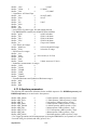
DMMArmAnalogTrigger ................................................................................................................68
DMMArmTrigger............................................................................................................................69
DMMBurstBuffRead .......................................................................................................................70
DMMBurstRead ..............................................................................................................................71
DMMCalibrate................................................................................................................................72
DMMCleanRelay ............................................................................................................................72
DMMClearMinMax ........................................................................................................................73
DMMCloseUSB...............................................................................................................................73
DMMDelayedTrigger .....................................................................................................................74
DMMDisableTrimDAC...................................................................................................................75
DMMDisarmTrigger.......................................................................................................................75
DMMDutyCycleStr .........................................................................................................................76
DMMErrString................................................................................................................................76
DMMFrequencyStr .........................................................................................................................77
DMMGetACCapsR .........................................................................................................................77
DMMGetAperture ...........................................................................................................................78
DMMGetAverageVAC ....................................................................................................................79
DMMGetBufferSize.........................................................................................................................79
DMMGetBusInfo.............................................................................................................................80
DMMGetCalDate............................................................................................................................80
DMMGetdB.....................................................................................................................................82
DMMGetdBStr ................................................................................................................................82
DMMGetCJTemp............................................................................................................................83
DMMGetCounterRange..................................................................................................................83
DMMGetDeviation .........................................................................................................................84
DMMGetDeviatStr..........................................................................................................................84
DMMGetDevLocation.....................................................................................................................85
DMMGetDiffMnMxStr ....................................................................................................................86
DMMGetFuncRange.......................................................................................................................86
DMMGetFunction...........................................................................................................................87
DMMGetGrdVer .............................................................................................................................87
DMMGetHwVer..............................................................................................................................88
DMMGetHwOption.........................................................................................................................88
DMMGetID .....................................................................................................................................89
DMMGetLowFreqVRMS ................................................................................................................89
DMMGetManDate ..........................................................................................................................90
DMMGetMax ..................................................................................................................................90
DMMGetMaxStr .............................................................................................................................91
DMMGetMin...................................................................................................................................91
DMMGetMinStr ..............................................................................................................................92
DMMGetNumDevices .....................................................................................................................93
DMMGetRange ...............................................................................................................................93
DMMGetReadInterval ....................................................................................................................94
DMMGetSourceFreq ......................................................................................................................94
DMMGetStoredReading .................................................................................................................95
DMMGetSourceMode .....................................................................................................................95
DMMGetTCType.............................................................................................................................96
DMMGetTrigger .............................................................................................................................96
5
Signametrics
DMMGetTriggerInfo.......................................................................................................................97
DMMGetType .................................................................................................................................98
DMMGetVer ...................................................................................................................................98
DMMInit .........................................................................................................................................99
DMMIsAutoRange ..........................................................................................................................99
DMMIsInitialized..........................................................................................................................100
DMMIsRelative .............................................................................................................................100
DMMLongTrigger ........................................................................................................................101
DMMLongTrigRead......................................................................................................................102
DMMOpenCalACCaps .................................................................................................................103
DMMOpenTerminalCal................................................................................................................103
DMMOpenUSB .............................................................................................................................104
DMMOutputSync ..........................................................................................................................104
DMMPeriodStr .............................................................................................................................105
DMMQuickInit..............................................................................................................................107
DMMRead.....................................................................................................................................107
DMMReadBuffer...........................................................................................................................108
DMMReadBufferStr ......................................................................................................................109
DMMReadCJTemp .......................................................................................................................109
DMMReadCrestFactor .................................................................................................................110
DMMReadDutyCycle ....................................................................................................................111
DMMReadSR ................................................................................................................................111
DMMReadFrequency....................................................................................................................112
DMMReadHiLoSense ...................................................................................................................113
DMMReadHiSense........................................................................................................................113
DMMReadInductorQ ....................................................................................................................114
DMMReadInductorR.....................................................................................................................114
DMMReadLoSense .......................................................................................................................115
DMMReadMeasurement ...............................................................................................................116
DMMReadMedian.........................................................................................................................116
DMMReadNorm............................................................................................................................117
DMMReadNsamples .....................................................................................................................118
DMMReadPeakToPeak.................................................................................................................118
DMMReadPeriod..........................................................................................................................119
DMMReadStr ................................................................................................................................119
DMMReadTestV............................................................................................................................120
DMMReadTotalizer ......................................................................................................................121
DMMReadWidth ...........................................................................................................................121
DMMReady ...................................................................................................................................122
DMMSetACCapsDelay .................................................................................................................122
DMMSetACCapsLevel ..................................................................................................................123
DMMSetACVSource .....................................................................................................................124
DMMSetAperture..........................................................................................................................125
DMMSetAutoRange ......................................................................................................................125
DMMSetBuffTrigRead ..................................................................................................................126
DMMSetCapsAveSamp .................................................................................................................127
DMMSetCJTemp...........................................................................................................................128
DMMSetCompThreshold ..............................................................................................................128
DMMSetCounterRng.....................................................................................................................129
DMMSetDCISource ......................................................................................................................130
DMMSetDCVSource .....................................................................................................................131
DMMSetFastRMS .........................................................................................................................132
DMMSetFuncRange......................................................................................................................132
DMMSetFunction..........................................................................................................................133
DMMSetInductFreq ......................................................................................................................133
DMMSetOffsetOhms .....................................................................................................................134
DMMSetPLC.................................................................................................................................134
DMMSetPulseGen.........................................................................................................................135
DMMSetRange..............................................................................................................................136
DMMSetReadInterval ...................................................................................................................137
Signametrics
6
DMMSetReference ........................................................................................................................138
DMMSetRelative ...........................................................................................................................138
DMMSetRTD ................................................................................................................................139
DMMSetSensorParams.................................................................................................................139
DMMSetSourceMode....................................................................................................................140
DMMSetSourceRes .......................................................................................................................141
DMMSetSync ................................................................................................................................141
DMMSetTCType ...........................................................................................................................143
DMMSetTempUnits.......................................................................................................................143
DMMSetTrigPolarity ....................................................................................................................144
DMMSetTrigRead .........................................................................................................................144
DMMSetTrimDAC ........................................................................................................................146
DMMStartTotalizer.......................................................................................................................146
DMMStopTotalizer .......................................................................................................................147
DMMTerminate.............................................................................................................................148
DMMTrigger.................................................................................................................................148
DMMTriggerBurst ........................................................................................................................149
DMMUnlockCounter ....................................................................................................................150
DMMWaitForTrigger ...................................................................................................................151
DMMWidthStr...............................................................................................................................151
5.7 CALIBRATION AND SERVICE COMMANDS ...............................................................................................153
AC_zero ........................................................................................................................................153
DMMLoadCalFile.........................................................................................................................154
SetGain..........................................................................................................................................154
GetGain.........................................................................................................................................155
GetOffset .......................................................................................................................................155
SetFcomp ......................................................................................................................................156
SetOffset ........................................................................................................................................157
Linearize_AD ................................................................................................................................157
Read_ADcounts ............................................................................................................................158
WrCalFileToStore.........................................................................................................................158
WrCalStoreToFile.........................................................................................................................159
DMMGetSupplyV..........................................................................................................................159
5.8 SERVICE COMMANDS .............................................................................................................................161
GrdXingTest..................................................................................................................................161
ClearBuffer ...................................................................................................................................162
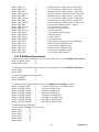
5.9 ERROR CODES ........................................................................................................................................162
5.10 WARNING CODES .................................................................................................................................163
5.11 PARAMETER LIST .................................................................................................................................163
5.11.1 Measurement and Source Functions..................................................................................163
5.11.2 Composite Function-Range ...............................................................................................164
5.11.3 Function Values .................................................................................................................166
5.11.4 Range Values .....................................................................................................................167
5.11.5 Aperture parameters ..........................................................................................................168
5.11.6 Additional parameters .......................................................................................................169
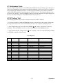
6.0 MAINTENANCE ..............................................................................................................................................170
6.1 PERFORMANCE TESTS ............................................................................................................................171
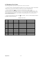
6.2 DC VOLTAGE TEST ................................................................................................................................171
6.3 RESISTANCE TEST, 2-WIRE .....................................................................................................................172
6.4 RESISTANCE TEST, 4-WIRE .....................................................................................................................173
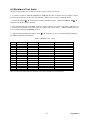
6.5 AC VOLTAGE TEST ................................................................................................................................174
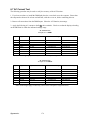
6.6 DC CURRENT TEST ................................................................................................................................175
6.7 AC CURRENT TEST ................................................................................................................................176
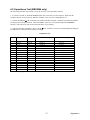
6.8 CAPACITANCE TEST (SMU2064 ONLY)..................................................................................................177
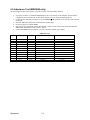
6.8 INDUCTANCE TEST (SMU2064 ONLY)....................................................................................................178
6.9 FREQUENCY COUNTER TEST ( SMU2064 ONLY)....................................................................................179
6.10 CALIBRATION .......................................................................................................................................180
7.0 WARRANTY AND SERVICE.........................................................................................................................182
7
Signametrics
8.0 ACCESSORIES.................................................................................................................................................182
1.0 Introduction
Congratulations! You have purchased a Personal Computer (PC) USB with analog and systems performance that
rivals the best Digital Multimeters on the market. These all-in-one Digital Multimeters (DMM’s) are easy to setup
and use, have sophisticated analog and digital circuitry to provide very repeatable and super accurate measurements,
and are protected to handle any unexpected situations your measurement environment may encounter. To get years
of reliable service from these DMM’s, please take a few moments and review this manual before installing and
using this precision instrument.
This manual describes the SMU2060 and SMU2064 DMMs.
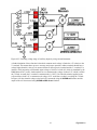
1.1 Safety Considerations
Safety Considerations
The SMU2060 series of USB Digital Multimeters (DMMs) are capable of measuring up to 330 VDC or
330 VAC across the Volt HI and LO terminals, and can also measure common mode signals that "float"
the DMM above EARTH ground by up to 330 VDC or 250 VAC. When making common mode
measurements, the majority of the circuits inside the DMM are at the common mode voltage. These
voltages can be lethal.
The DMM enclosure must not be tempered or disassembled for any reason. Doing so will result in
performance degradation and will present a safety risk. Improper handeling of these products can
result in lethal voltages that may effect the computer this product is connected to.
Warning
No probes or any other wiring should be connected to the DMMs during installation or removal of
the USB to the DMM or to the Computer. Not doing so may apply lethal measurement voltages to
your computer and USB cable, causing electrocution and/or damage to your computer and/or your
DMM.
To avoid shock hazard, connect the USB cable only to a computer that has its power connector
connected to a power receptacle with an earth safety ground.
When making any measurements above 50 VDC or 40 VAC, only use Safety Test Leads. Examples
of these are the Signametrics Basic Test Leads and Deluxe Test Leads, offered as an accessory with the
Signametrics DMM’s.
1.2 Minimum Requirements
These USB DMMs are precision plug-in modules that are compatible with personal computers (PCs). It requires as
a minimum a Pentiums computer. A mouse or a compatible pointing device must be installed when controlling the
DMM from the Windows Control Panel provided with this product. These DMMs comes with a Windows' DLL,
for operation with Windows' Version 95/98/Me/2000/XP and Milenium.
1.3 Feature Set
The base unit, the SMU2060, has traditional 7-1/2 digit features and it can be used as a general purpose DMM,
where accuracy and speed are important. The High Workload Multi Function SMU2064 adds timing, capacitance,
inductance, sourcing , leakage and more speed. With its specialized measurements, it can replace several costly
instruments, shrinking the size and cost of a test system. It is possible to deploy several SMU2060s, SMU2064s and
Signametrics
8
SMU2055 DMMs in a single computer, in any mix. Multiple units add both, overall system throughput and
comlexity.
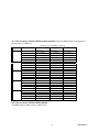
SMU2060 and SMU2064 7½ Digit DMM’s feature table:
Function
SMU2055
SMU2060
SMU2064
DCV five ranges 240mV to 330V
ACV five ranges 240mV to 330V
2-Wire Ohms, six ranges 240 to 24 M
4-Wire Ohms, six ranges 240 to 24 M
DC current, four ranges 2.4 mA to 2.4 A
AC current, four ranges 2.4 mA to 2.4 A
Diode V/I characteristics at 100 A to 1mA
Auto range, Relative
Min/Max, dB and percent deviation functions
On board measurement buffer
External and threshold trigger
Thermocouples types; B, E, J, K, N, R, S, T
High Dynamic range; +24,000,000 counts
Frequency / Period measurement
Measurement rate: (rdngs/sec)
Capacitance, ramp type, eight ranges, 1 nF to 10 mF
RTD types: pt385, 3911, 3916, 3926, Copper, variable Ro
Internal DMM temperature sensor
Component Handler Interface (for volume prouction)
Capacitance, In-Circuit method five ranges, 24nF to 2.4mF
Inductance, six ranges 33 H to 3.3 H
Offset Ohms
Pulse width, pos./neg., & duty cycle
Totalizer/event counter
Variable threshold DAC; all timing measure.
Peak to Peak, Crest factor, Median
Six wire Ohms (with force/sense)
DCV source to ±10.0 V
ACV source 0 to 20 V pk-pk, 0.5 Hz to 200 KHz
DC current source, 1 nA to 12.5 mA
Leakage at ±10.0V, 240nA, 2.4uA and 25uA ranges.
2-Wire Ohms two additional ranges 24 and 240 M
4-Wire Ohms additional range 24
Extended Resistance with V&I limits (to 100G)
DC Current , additional ranges 240nA, 2.4A, 24A, 240A
Two auxiliary VDC inputs
Source 0 - ±10V / Measure to 0 - ±24mA
Stimulate and Measure Load cells and Strain gauges
Average AC Voltage, 240mV, 2.4V, 24V, 240V, 330V (1Hz to 1kHz)
Low frequency true RMS (0.2Hz to 66Hz)
(-330V)
(-330V)
1350
(plus 10mA)
20,000
9
375
Signametrics
2.0 Specifications
The following specifications should be considered under the environment specified.
To meet its specified accuracy specs, allow a warm up for at least one-half hour.
It is important to note that a DMM specified range is expressed as a numeric value indicating the highest
absolute voltage that can be measured. The lowest value that can be detected, or sensitivity is expressed
by the corresponding resolution for the range.
2.1 DC Voltage Measurement
Input Characteristics
Input Resistance 240 mV, 2.4 V Ranges: >10 G, with typical leakage of 50pA
Input Resistance 24 V, 240 V, 330V Ranges: 10.00 M
Accuracy ± (% of reading + Volts) [1]
Range
240 mV
2.4 V
24 V
240 V
330 V
Full Scale
7-½ Digits
240.00000 mV
2.4000000 V
24.000000 V
240.00000 V
330.00000 V
Resolution
10 V
100 V
1 V
10 V
10 V
24 hours
23C 1C
0.003 + 1 V
0.002 + 3 V
0.004 + 120 V
0.003 + 250 V
0.0075 + 550 V
90 Days
23C 5C
0.004 + 1.5 V
0.0025 + 4 V
0.005 + 130 V
0.004 + 300 V
0.01+ 700 V
One Year 23C
5C
0.005 + 2 V
0.003 + 5 V
0.006 + 150 V
0.005 + 0.5 mV
0.015 + 0.8 mV
[1] With Aperture set to ≥ 0.5 Sec, and within one hour from Self Calibration (S-Cal).
For resolution at smaller Apertures, see the following table. Use this table for DC Volts, DC current and
Resistance measurements.
Measurement Aperture
SMU2060, SMU2064
Aperture > 0.5 s
Aperture 10 ms
Aperture 625s
Aperture > 2.5us [2]
Maximum reading
rate
2 / second
100 / second
1200 / second
20,000 / second [2]
Resolution
7-1/2 digits
25 bits
6-1/2 digits
22 bits
5-1/2 digits
18 bits
4 digits
14 bits
[2] Available only with the SMU2064.
DCV Noise Rejection Normal Mode Rejection, at 50, 60, or 400 Hz ± 0.5%, is better than 95 dB for
apertures of 0.160s and higher. Common Mode Rejection (with 1 k lead imbalance) is better than 120
dB for these conditions.
2.2 DC Current Measurement
Input Characteristics
Number of shunts Five in SMU2064, two in the SMU2060
Burden Voltage 240mV max.
Protected with 2.5A Fast blow fuse
Accuracy ± (% of reading + Amps) [1]
Range
240 A [2]
2.4 A [2]
24 A [2]
240 A [2]
2.4 mA
24 mA
240 mA
2.4 A
Full Scale
Reading
240.0000 A
2.400000 A
24.00000 A
240.000 A
2.40000 mA
24.0000 mA
240.000 mA
2.40000 A
Resolution
0.1 pA
1 pA
10 pA
10 A
10 A
100 A
1 A
10 A
Max Burden
Voltage
100 V
100 V
100 V
2.5mV
25mV
250mV
55mV
520mV
24 hours
23C 5C
0.07 + 40pA
0.05 + 70pA
0.05 + 400pA
0.052 + 200 A
0.05 + 300 A
0.05 + 350 A
0.05 + 50 A
0.3 + 60 A
90 Days
23C 5C
0.1 + 45pA
0.08 + 90pA
0.08 + 600pA
0.07 + 300 A
0.06 + 400 A
0.065 + 450 A
0.055 + 60 A
0.4 + 70 A
[1] With Aperture set to ≥ 0.96 Sec, and within one hour from Zero (Relative control).
Signametrics
10
One Year
23C 5C
0.17 + 60pA
0.21 + 150pA
0.13 + 0.8nA
0.1 + 400 A
0.07 + 550 A
0.08 + 550 A
0.065 + 80 A
0.45 + 90 A
[2] Available only with the SMU2064.
2.3 Resistance Measurements
Input Characteristics
Number of Current Sources seven in SMU2064, five in the SMU2060
Burden Voltage 240mV or 2.4V max, depending on range.
Range
24 [1]
240
2.4 k
24 k
240 k
2.4 M
24 M
240 M[1]
Full Scale Reading
24.000000
240.00000
2.4000000 k
24.000000 k
240.00000 k
2.4000000 M
24.0000 M
240.000 M
Resolution
1
10
100
1 m
10 m
100 m
100
1 k
Test current
10 mA
1 mA
1 mA
100 A
10 A
1 A
100 nA
4 nA
Maximum Test Voltage (at Full Scale)
240mV
240mV
2.4V
2.4V
2.4V
2.4V
2.4V
1.0V
[1] Ranges are only available in the SMU2064.
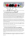
2.3.1 2-wire
Accuracy ± (% of reading + ) [1]
Range
24
240
2.4 k
24 k
240 k
2.4 M
24 M
240 M
24 hours 23C 1C
0.0038 + 1.4 m [2]
0.0037 + 4.5 m [2]
0.0023 + 28 m
0.0025 + 300 m
0.0055 + 3.2
0.018 + 40
0.12 + 400
0.8 + 20 k
90 Days 23C 5C
0.005 + 1.6 m [2]
0.0046 + 5 m [2]
0.004 + 32 m
0.004 + 330 m
0.006 + 4
0.03 + 50
0.13 + 500
1.0 + 30 k
One Year 23C 5C
0.008 + 2 m [2]
0.007 + 6 m [2]
0.006 + 33 m
0.006 + 350 m
0.007 + 5
0.04 + 70
0.2 + 600
1.3 + 50 k
[1] With Aperture set to ≥ 0.5 Sec, and within one hour from Self Calibration (S-Cal).
[2] Use of S-Cal and Relative to improve measurement floor.
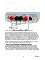
2.3.2 4-wire
Accuracy ± (% of reading + ) [1]
Range
24
240
2.4 k
24 k
240 k
2.4 M
24 M
Maximum Lead
Resistance
50
500
500
5 k
50k
50 k
50 k
24 hours
23C 1C
0.0038 + 0.7 m [2]
0.0037 + 3 m [2]
0.0023 + 28 m
0.0025 + 300 m
0.0055 + 3.2
0.018 + 40
0.12 + 400
90 Days
23C 5C
0.005 + 0.8 m [2]
0.0046 + 4 m [2]
0.004 + 32 m
0.004 + 330 m
0.007 + 4
0.03 + 50
0.13 + 500
One Year
23C 5C
0.008 + 1 m [2]
0.007 + 5 m [2]
0.006 + 33 m
0.006 + 350 m
0.007 + 5
0.04 + 70
0.2 + 600
[1] With Aperture set to ≥ 0.5 Sec, and within one hour from Self Calibration (S-Cal).
[2] Use of Relative to facilitate indicated floor (adder part of spec).
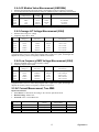
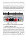
2.3.3 6-wire Guarded Resistance Measurement (SMU2064)
This is an in-circuit forced guard measurement method, as implemented in ICT testers. Add this typical
additional error to the above specification.
Accuracy ± (% of reading + )
Range
24
240
2.4 k
24 k
240 k
24 M
Max Guard forced current
20 mA
20 mA
20 mA
100 A
10 A
1 A
One Year 23C 5C [1] (adder)
0.3 + 4 m
0.003 + 20 m
0.005 + 100 m
0.03 + 1
0.35 + 10
0.85 + 1000
[1] This table should be used in conjunction with the 2-wire and 4-wire table above.
11
Signametrics
2.3.4 Extended Resistance Measurements (SMU2064)
Characteristics
Test Voltage Adjustable between -10V and +10V in 5mV steps
Accuracy ± (% of reading + Amps) [1]
Range
Resol
Current Limit [3]
90 Days
One Year 23C
Measurement range
23C 5C
ution
5C
25µA
0.2 + 50
400k
1k to 100M
10
0.33 + 90
0.3 + 350
4M
10k to 1G
100 2.5µA
0.43 + 550
250nA
0.4 + 3k
40M
100k to 10G
1k
0.55 + 4.5k
[1] With Aperture set to ≥ 0.5 Sec, and within one hour from Zero (Relative control).
[2] Multiply “% of reading” by 1/Voltage Source for applied voltages below 1V
[3] Limit is reached when the test current exceeds the Current Limit, or it is below 0.04% of this value.
2.3.5 Offset Ohms Measurements (SMU2064)
The purpose of Offset Ohms is to compensate for errors due to DC voltages which are in series with the
resistance being measured. DMMSetOffsetOhms() function provides the means to control this
operation. It is disabled by default.
Characteristics
Offset correction range: 240mV or 2.4V depending on selected range
Application: 2-Wire and 4-Wire Ohms
Offset voltage: Depends on head-room; range and measured resistance value.
Range
Measurement limits [2]
Vo limits [1]
-230mV to 230mV
I*R + Vo < +220mV
24 & 240
-2.3V to 2.3V
I*R + Vo < +2.2V
2.4k to 24M
[1] With resistance, R, less than 10% of range.
[2] R – Measured resistance, I – Test current, Voofset – Offset Voltage
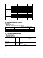
2.4 AC Voltage Measurements
Input Characteristics
Input Resistance 1 M, shunted by < 300 pF, all ranges
Max. Crest Factor 4 at Full Scale, increasing to 7 at Lowest Specified Voltage
AC coupled Specified range: 10 Hz to 100 kHz
Typical Settling time < 0.5 sec to within 0.1% of final value
Typical Settling time, Fast RMS < 0.05 sec to within 0.1% of final value
2.4.1 AC Voltage True RMS Measurement
Range
240 mV
2.4 V
24 V
240 V
330 V
Full Scale 7-½ Digits
240.0000 mV
2.400000 V
24.00000 V
240.0000 V
330.0000 V
Lowest specified Voltage
5 mV [1]
20 mV
200 mV
2V
2.5 V
Resolution
100 V
1 V
10 V
100 V
100 V
[1] Between 5 mV and 10 mV, add 100 V additional errors to the accuracy table below.
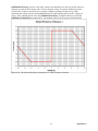
[2] Signal is limited to 8x10⁶ Volt Hz Product. For example, the largest frequency input at 250 V is 32 kHz, or
8x10⁶ Volt x Hz.
ACV Noise Rejection Common Mode rejection, for 50 Hz or 60 Hz with 1 k imbalance in either lead, is better
than 60 dB.
Signametrics
12
AC Volts Accuracy with Fast RMS disabled (default). With Fast RMS disabled, settling time to
rated accuracy is within 0.5s:
Accuracy ± (% of reading + Volts) [1]
Range
240 mV
2.4 V
24 V
240 V
330 V
Frequency
10 Hz - 20 Hz
20 Hz - 47 Hz
47 Hz - 10 kHz
10 kHz - 50 kHz
50 kHz - 100 kHz
10 Hz - 20 Hz
20 Hz - 47 Hz
47 Hz - 10 kHz
10 kHz - 50 kHz
50 kHz - 100 kHz
10 Hz - 20 Hz
20 Hz - 47 Hz
47 Hz - 10 kHz
10 kHz - 50 kHz
50 kHz - 100 kHz
10 Hz - 20 Hz
20 Hz - 47 Hz
47 Hz - 10 kHz
10 kHz - 50 kHz
50 kHz - 100 kHz
10 Hz - 20 Hz
20 Hz - 47 Hz
47 Hz - 10 kHz
10 kHz - 50 kHz
50 kHz - 100 kHz
24 hours
23C 1C
3.0 + 350 V
0.37 + 150 V
0.2 + 100 V
0.25 + 160 V
1.9 + 350 V
3.0 + 2 mV
0.37 + 1.3 mV
0.05 + 1 mV
0.32 + 1.2 mV
1.9 + 1.5 mV
3.0 + 14 mV
0.37 + 12 mV
0.06 + 10 mV
0.18 + 18 mV
1.3 + 30 mV
3.0 + 140 mV
0.37 + 120 mV
0.04 + 100 mV
0.28 + 150 mV
1.4 + 200 mV
3.0 + 200 mV
0.43 + 180 mV
0.07 + 150 mV
0.28 + 200 mV
1.3 + 270 mV
90 Days
23C 5C
3.1 + 380 V
0.38 + 170 V
0.21 + 110 V
0.26 + 200 V
1.95 + 370 V
3.1 + 2.2 mV
0.38 + 1.5 mV
0.055 + 1.1 mV
0.33 + 1.3 mV
2.0 + 1.7 mV
3.1 + 16 mV
0.37 + 14 mV
0.065 + 11 mV
0.2 + 21 mV
1.4 + 35 mV
3.1 + 160 mV
0.38 + 130 mV
0.045 + 110 mV
0.29 + 170 mV
1.5 + 240 mV
3.1 + 160 mV
0.44 + 200 mV
0.08 + 200 mV
0.30 + 250 mV
2.4 + 350 mV
One Year
23C 5C
3.2 + 430 V
0.4 + 200 V
022 + 120 V
0.27 + 230 V
2.0 + 400 V
3.2 + 2.5 mV
0.4 + 1.7 mV
0.065 + 1.2 mV
0.35 + 1.5 mV
2.1 + 2 mV
3.3 + 20 mV
0.4 + 16 mV
0.073 + 13 mV
0.22 + 25 mV
1.5 + 40 mV
3.3 + 200 mV
0.4 + 150 mV
0.06 + 130 mV
0.30 + 200 mV
1.6 + 300 mV
3.3 + 200 mV
0.45 + 250 mV
0.09 + 230 mV
0.32 + 300 mV
1.6 + 400 mV
[1] With Aperture set to ≥ 0.5 Sec
AC Volts Accuracy with Fast RMS enabled.
Fast RMS settles to rated accuracy within 50ms.
13
Signametrics
Accuracy ± (% of reading + Volts) [1]
Range
Frequency
240 mV
24 hours
23C 1C
0.6 + 150 V
0.13 + 100 V
0.55 + 160 V
5.3 + 350 V
0.93 + 1.3 mV
0.068 + 1 mV
0.62 + 1.2 mV
5.1 + 1.5 mV
0.93 + 12 mV
0.065 + 10 mV
0.31 + 18 mV
2.0 + 30 mV
0.93 + 120 mV
0.062 + 100 mV
0.32 + 150 mV
2.5 + 200 mV
1.0 + 180 mV
0.065 + 150 mV
0.34 + 200 mV
2.5 + 270 mV
350 Hz - 800 Hz
800 Hz - 10 kHz
10 kHz - 50 kHz
50 kHz - 100 kHz
350 Hz - 800 Hz
800 Hz - 10 kHz
10 kHz - 50 kHz
50 kHz - 100 kHz
350 Hz - 800 Hz
800 Hz - 10 kHz
10 kHz - 50 kHz
50 kHz - 100 kHz
350 Hz - 800 Hz
800 Hz - 10 kHz
10 kHz - 50 kHz
50 kHz - 100 kHz
350 Hz - 800 Hz
800 Hz - 10 kHz
10 kHz - 50 kHz
50 kHz - 100 kHz
2.4 V
24 V
240 V
330 V
90 Days
23C 5C
0.65 + 170 V
0.14 + 110 V
0.6 + 200 V
5.4 + 370 V
0.96 + 1.5 mV
0.075 + 1.1 mV
0.65 + 1.3 mV
5.2 + 1.7 mV
0.96 + 14 mV
0.068 + 11 mV
0.33 + 21 mV
2.2 + 35 mV
0.96 + 130 mV
0.065 + 110 mV
0.4 + 170 mV
2.8 + 240 mV
1.1 + 200 mV
0.07 + 200 mV
0.45 + 250 mV
2.8 + 350 mV
One Year
23C 5C
0.7 + 200 V
0.15 + 120 V
0.63 + 230 V
5.6 + 400 V
1.0 + 1.7 mV
0.08 + 1.2 mV
0.70 + 1.5 mV
5.3 + 2 mV
1.0 + 16 mV
0.073 + 13 mV
0.35 + 25 mV
2.4 + 40 mV
1.0 + 150 mV
0.08 + 130 mV
0.45 + 200 mV
3.2 + 300 mV
1.1 + 250 mV
0.08 + 230 mV
0.5 + 300 mV
3.2 + 400 mV
[1] With Aperture set to ≥ 0.16 Sec
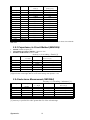
2.4.2 AC Peak-to-Peak Measurement (SMU2064)
Measures the peak-to-peak value of a repetitive waveform.
ACV
Range
240 mV
2.4 V
24 V
240 V
Lowest specified
input voltage (Vp-p)
0.1 V
1.0 V
10 V
100 V
Full Scale [2]
reading (Vp-p)
1.900 V
16.00 V
190.0 V
850.0 V
Typical Accuracy 23C 5C
One Year [1]
0.5 3 mV
0.5 ± 40 mV
0.5 ± 700 mV
0.55 ± 6 V
Resolution
1 mV
10 mV
100 mV
1V
[1] Signal frequency range 30 Hz to 60 kHz.
[2] USB power level greatly effects full scale reading.
2.4.3 AC Crest Factor Measurement (SMU2064)
Measures the crest factor (CF) of a repetitive waveform
ACV
Range
240 mV
2.4 V
24 V
240 V
Lowest specified
input voltage
(Vp-p)
0.1 V
1.0 V
10 V
100 V
Highest specified input
voltages (Vp-p)
Resolution
Typical Accuracy 23C 5C
One Year [1]
1.9 V
16 V
190 V
700 V
0.01
0.01
0.01
0.01
2.2 0.3
2.1 ±0.1
2.0 ±0.1
2.0 ±0.1
[1] Crest factor measurement requires signal frequency of 30 Hz to 60 kHz.
Signametrics
14
2.4.4 AC Median Value Measurement (SMU2064)
Measures the mid-point between the positive and negative peaks of a repetitive waveform
Used to determine the Threshold DAC setting for optimal frequency and timing measurements
ACV
Range
240 mV
2.4 V
24 V
240 V
Lowest specified input
voltage (Vp-p)
0.08 V
0.80 V
8V
80 V
Full Scale
reading
0.95 V
9.5 V
95.0 V
350.0 V
Resolution
Typical Accuracy 23C 5C One Year [1]
1 mV
10 mV
100 mV
1V
2.0% 17 mV
3% ±160 mV
3% ±1.4 V
3% ±12 V
[1] Median measurements require a repetitive signal with frequency range of 30 Hz to 30 KHz.
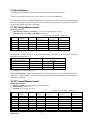
2.4.5 Average AC Voltage Measurement (2064)
Measures the average AC voltage
Frequency range 1Hz to 1kHz
Range
240 mV
2.4 V
24 V
240 V
330 V
Specified input
voltage [1]
240 mV
2.4 V
24 V
240 V
330 V
Full Scale reading:
sine wave
150.0 mV
1.500 V
15.00 V
150.0 V
200.0 V
Resolution
10 µV
100 µV
1 mV
10 mV
10 mV
Typical Accuracy 23C 5C
One Year [2]
1.5% 60 µV
1.2% ± 1 mV
1% ± 15 mV
1% ± 130 mV
1% ± 150 mV
[1] Requires selection of a DC Voltage range, and entry of signal frequency. Signal is repetitive.
[2] Specified for a sine wave. More abrupt signals such as square wave, pulse, and triangle will
degrade the accuracy relative to frequency contents of waveform.
2.4.6 Low frequency RMS Voltage Measurement (2064)
Measures the RMS value of a low frequency voltage
Frequency range 0.2Hz to 66Hz
Range
240 mV
2.4 V
24 V
240 V
330 V
Specified input
voltage [1]
240 mV
2.4 V
24 V
240 V
330 V
Full Scale reading:
sine wave
240.00 mV
2.4000 V
24.000 V
240.00 V
330.00 V
Resolution
10 µV
100 µV
1 mV
10 mV
10 mV
Typical Accuracy 23C 5C
One Year [2]
0.3% 50 µV
0.2% ± 500 µV
0.2% ± 5 mV
0.2% ± 50 mV
0.2% ± 70 mV
[1] Requires selection of a DC Voltage range, and entry of signal frequency. Signal is repetitive.
[2] Specified for a sine wave. More abrupt signals such as square wave, pulse, and triangle will
degrade the accuracy relative to frequency contents of waveform.
2.5 AC Current Measurement, True RMS
Input Characteristics
Crest Factor 4 at Full Scale, increasing to 10 at Lowest Specified Current
Burden Voltage 240mV max.
Protected with 2.5 A Fast Blow fuse
Range
Full Scale 6 1/2 Digits
2.4 mA
24 mA
240 mA
2.4 A
2.400000 mA
24.00000 mA
240.0000 mA
2.400000 A
Lowest Specified
Current
60 A
300 A
3 mA
30 mA
Maximum Burden
Voltage (RMS)
25mV
250mV
55mV
520mV
15
Resolution
1 nA
10 nA
100 nA
1 uA
Signametrics
Accuracy ± (% of reading + Amps)
Range
2.4 mA
24 mA
240 mA
2.4 A
Frequency [1]
24 hours
23C 1C
3.8 + 4 A
0.9 + 4 A
0.04 + 1.5 A
0.12 + 4 A
1.8 + 30 A
0.6 + 30 A
0.07 + 10 A
0.21 + 30 A
1.8 + 400 A
0.6 + 400 A
0.1 + 100 A
0.3 + 300 A
1.8 + 4 mA
0.66 + 4 mA
0.3 + 3.8mA
0.4 + 4mA
10 Hz - 20 Hz
20 Hz - 47 Hz
47 Hz - 1 kHz
1 kHz - 10 kHz
10 Hz - 20 Hz
20 Hz - 47 Hz
47 Hz - 1 kHz
1 kHz - 10 kHz
10 Hz - 20 Hz
20 Hz - 47 Hz
47 Hz - 1 kHz
1 kHz - 10 kHz
10 Hz - 20 Hz
20 Hz - 47 Hz
47 Hz - 1 kHz
1 kHz - 10 kHz
90 Days
23C 10C
2.7 + 4 A
0.9 + 4 A
0.08 + 3 A
0.14 + 4 A
2.6 + 30 A
0.9 + 30 A
0.15 + 20 A
0.3 + 40 A
2.7 + 400 A
0.9 + 400 A
0.17 + 180 A
0.35 + 350 A
2.5 + 4.5 mA
0.8 + 6 mA
0.33 + 3.8 mA
0.45 + 4.5 mA
One Year
23C 10C
2.9 + 4 A
1.0 + 4 A
0.12 + 4 A
0.22 + 4 A
2.8 + 30 A
1.0 + 30 A
0.16 + 30 A
0.4 + 40 A
2.8 + 400 A
1.0 + 400 A
0.2 + 220 A
0.4 + 400 A
2.7 + 5 mA
0.9 + 6 mA
0.35 + 4 mA
0.5 + 5 mA
[1] All AC Current ranges have typical measurement capability of at least 20 kHz.
2.6 Leakage Measurement (SMU2064)
Characteristics
Burden Voltage: < 100 V
Test Voltage: Adjustable between -10V to +10V in 5mV steps
Accuracy ± (% of reading + Amps) [1]
Range
240 A
2.4 A
24 A
Full Scale
6-½ Digits
240.0000 A
2.400000 A
24.00000 A
Resolution
0.1 pA
1 pA
10 pA
24 hours
23C 5C
0.07 + 40pA
0.05 + 70pA
0.05 + 400pA
90 Days
23C 5C
0.1 + 45pA
0.08 + 90pA
0.08 + 600pA
One Year 23C
5C
0.17 + 60pA
0.21 + 150pA
0.13 + 0.8nA
[1] With Aperture set to ≥ 0.5 Sec, and within one hour from Zero (Relative control).
2.7 RTD Temperature Measurement
Ro: Variable 10 to 10 k
Measurement Method: 4-Wire
Temperature units: Selectable oC or oF
RTD Type
0.01C
Temperature
range
-150 to 650C
Temperature Accuracy 23C 5C [1]
One Year
0.06C
500, 1 k
0.01C
-150 to 650C
0.03C
Less than 12
0.01C
-100 to 200C
Higher than 90
0.01C
-100 to 200C
0.18C for temperatures 20C, 0.05C
otherwise
0.10C for temperatures 20C, 0.05C
otherwise
Ro ()
Resolution
pt385, pt3911,
pt3916, pt3926
pt385, pt3911,
pt3916, pt3926
Cu (Copper)
100, 200
Cu (Copper)
[1] With Aperture of 0.5s and higher, using a 4-wire RTD. Measurement accuracy does not include RTD probe
error.
Signametrics
16
2.8 Thermocouple Temperature Measurement
Cold Junction Compensation: By Sensor measurement or soft entry.
Cold Junction Temperature range: 0 oC to 50 oC
Cold Junction Sensor: Use SMX40T or SM40T Isothermal unit, or define sensor equation
Isothermal Block compatibility: SM4022, SM4042, SMX4032, SM40T, SMX40T
Temperature units: Selectable oC or oF
TC Type
B
E
J
K
N
R
S
T
Resolution
0.01C
0.01C
0.01C
0.01C
0.01C
0.01C
0.01C
0.01C
Maximum Temperature
[2]
2200C
1200C
2000C
3000C
3000C
2700C
3500C
550C
Temperature Accuracy 23C 5C [1]
One Year
0.38 C
0.035 C
0.06 C
0.07 C
0.10 C
0.25 C
0.35 C
0.06 C
[1] With Aperture of 0.5s and higher. Measurement accuracy does not include Thermocouple error.
[2] DMM Linearization temperature range may be greater than that of the Thermocouple device.
2.9 Additional Component Measurement Capability
2.9.1 Diode Characterization
Available Test currents 100 A, 1 A, 10 A, 100 A and 1 mA
SMU2064 add variable current of 10 A to 12.5 mA
One Year Current Source Uncertainty 2.5%.+ 2A
One Year Voltage Measurement Uncertainty 0.01% + 50uV
Voltage measurement range 0V to 2.4V
2.9.2 Capacitance
Method Charge Balance.
Speed Very high, for high volume production
Accuracy ± (% of reading + Farads) [1]
Range
1,200 pF
12 F
120 F
1.2 F
12 F
120 F
1.2 mF
12 mF
Full Scale
Reading (SMU2064)
1,199.9 pF
11.999 F
119.99 F
1.1999 F
11.999 F
119.99 F
1.1999 mF
50.000 mF
SMU2060
Resolution
1 pF
10 pF
100 pF
1 nF
10 F
100 F
1 F
10 F
SMU2064
Resolution
0.1 pF
1 pF
10 pF
100 pF
1 F
10 F
100 F
1 F
One Year
23C 5C
1 ± 1 pF [2]
1.2 ± 5 pF [3]
1.0 [3]
1.0 [3]
1.0 [3]
1.0 [3]
1.2 [3]
2 [3]
[1] Within one hour of zero, using Relative control. Specified at DMM input terminals.
[2] Accuracy is specified for values higher than 5% of the selected range.
[3] For values between 200pf and 500pf the floor is 2.5pf rather than 1pf.
This Measurement is independent of set Aperture and Read Interval. If desired, the DMMSetCapsAveSamp()
function may be used to control measurement parameters. It is provided means to fine tune the measurement timing for
the application, trading off accuracy for speed.
Measurement time will vary as function of the set parameters, selected range and measured capacitance. The following are
measurement times associated with the default parameters, as range is selected.
17
Signametrics
Range
Input
1,200 pF
1,200 pF
5% of Scale
Full Scale
5% of Scale
Full Scale
5% of Scale
Full Scale
5% of Scale
Full Scale
5% of Scale
Full Scale
5% of Scale
Full Scale
5% of Scale
Full Scale
5% of Scale
Full Scale
Typical Measurement
Time [1]
Typical Measurement
speed (rps) [1]
19.5 ms
51.3
52.3 ms
19.1
12 F
70.0 ms
14.3
12 F
118ms
8.5
120 F
8.9 ms
112.4
120 F
127 ms
7.9
1.2 F
15.6 ms
64.1
1.2 F
175 ms
5.7
12 F
14.1 ms
70.9
12 F
480 ms
2.1
120 F
17.3 ms
57.8
120 F
50.3 ms
19.9
1.2 mF
52.6 ms
19.0
1.2 mF
151.5 ms
6.6
12 mF
52.8 ms
18.9
12 mF
170 ms
5.9
[1] This time depends on the value measured capacitance. The SMU2060 is about 10 times slower than the
SMU2064.
2.9.3 Capacitance, In-Circuit Method (SMU2064)
Method Variable frequency AC
Adjustable Peak Voltages Stimulus 100mV to 5.0V
Parallel Load Resistance as low as 100
Accuracy ± (% of reading + Farads) [1]
Range
24 F
240 F
2.4 F
24 F
240 F
2.4 mF
Full Scale
3-½ Digits
23.99 F
239.9 F
2.399 F
23.99 F
239.9 F
2.399 mF
Resolution
10 pF
100 pF
1000 pF
10 F
100 F
1 F
One Year
23C 5C [2]
5 ± 200 pF
5 ± 1 F
3 ± 5 F
3 ± 50 F
5 ± 500 F
6 ± 5 F
[1] Within one hour of AC Caps Open Cal operation, and relative correction.
[2] Specified for values higher than 5% of the selected range with Aperture > 0.2s
2.9.4 Inductance Measurement (SMU2064)
Accuracy ± (% of reading + inductance) [1]
Range
Test frequency
33 H
330 H
3.3 mH
33 mH
330 mH
3.3 H
100 kHz
50 kHz
4 kHz
1.5 kHz
1 kHz
100 Hz
Full Scale
4 ½ Digits
33.000 H
330.00 H
3.3000 mH
33.000 mH
330.00 mH
3.3000 H
Resolution
1 H
10 H
100 H
1 H
10 H
100 H
Accuracy 23C 5C
One Year [2]
3.0% + 500 H
2.0% + 3 H
1.5% + 25 H
1.5% + 200 H
2.5 + 3 mH
3 + 35 mH
[1] Within one hour of Zero, and Open Terminal Calibration.
[2] Accuracy is specified for values greater than 5% of the selected range.
Signametrics
18
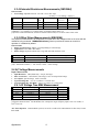
2.10 Time Measurements
2.10.1 Threshold DAC (SMU2064)
The Threshold DAC is used for selecting a detection level, providing optimal frequency and time
measurements even at extreme duty cycle values.
Accuracy ± (% of setting + volts)
Selected VAC
range [1]
Threshold range (DC
level)
240 mV
2.4 V
24 V
240 V
-1.0 V to +1.0 V
-10.0 V to +10.0 V
-100.0 V to 100.0 V
-400 V to 400 V
Threshold
DAC
resolution
0.5 mV
5.0 mV
50 mV
500 V
Highest allowed input
Vp-p
Typical one year setting
uncertainty
1.900 V
19.00 V
190.0 V
850.0 V
0.2% + 4 mV
0.2% + 40 mV
0.2% + 0.4 V
0.2% + 4 V
[1] This table should be used in conjunction with the AC volts section above.
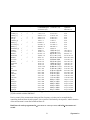
2.10.2 Frequency and Period Measurements
Input Impedance 1 M with < 300 pF for voltage, 0.15 to 10 for current.
Ranging Auto-Ranging (default) or Range-Lock
Maximum acquisition time while in Auto-Ranging mode 7s
Acquisition Time in Range Locked mode 35ms to 2s
Frequency
1Hz – 130Hz
130Hz – 640Hz
640Hz – 2.5kHz
2.5kHz – 40kHz
40kHz – 200kHz
200kHz – 300kHz
One Year accuracy (% of
reading + Hz)
0.025% + 0.0015Hz
0.025% + 0.02Hz
0.03% + 0.075Hz
0.03% + 1.2Hz
0.05% + 7Hz
0.07% + 5Hz
Resolution (Hz)
Minimum amplitued (VRMS)
1 mHz
6.5 mHz
25 mHz
0.4 Hz
2.5 Hz
1.5 Hz
30mV or 5% of range, whichever is
greater
25% of range
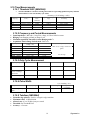
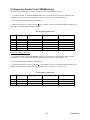
2.10.3 Duty Cycle Measurement
Frequency Range
2 Hz to 100 Hz
100 Hz to 1 kHz
1 kHz to 10 kHz
10 kHz to 100 kHz
Resolution
0.02%
0.2%
2%
20%
Typical Uncertainty is
±0.03% of reading ±
adder shown
Full scale reading
0.03%
0.3%
3%
20%
100.00 %
100.00 %
100.00 %
100.00 %
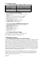
2.10.4 Pulse Width
± (% of reading + sec)
Polarity
Frequency range
Resolution
Width range
Positive or negative pulse
widths
2 Hz to 100 kHz
1 s
2 s to 1 s
Typical
Uncertainty
0.01 +/- 4 s
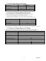
2.10.5 Totalizer (SMU2064)
Selectable edge polarity: Positive or negative edge transition
Maximum count: 10,000,000,000
Allowed rate: 0.2 to 45,000 events per second
Threshold: Set Threshold DAC
Accuracy: ±2 counts
19
Signametrics
2.11 Trigger Functions
2.11.1 External Hardware Trigger (at DIN-7 connector)
Trigger Input voltage level range
Minimum Trigger Pulse Width
Minimum trigger input current
Internal Reading Buffer
Edge
Isolation of trigger input
+3 V to +15 V activates the trigger.
1/Aperture + 50S
1 mA
Circular; 80 or 120 readings depending on resolution.
Selectable positive or negative edge.
±50 V from analog DMM inputs, and from chassis
earth ground.
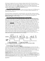
2.11.2 Analog Threshold Trigger
Trigger point: Selectable positive or negative transition of set threshold.
Buffer type: Circular
Captures: up to 120 post-trigger readings for apertures < 625uSec.
Captures: up to 80 post-trigger readings for apertures > 625uSec.
Aperture range: 160ms to 625S (to 2.5S with SMU2064)
Read Interval range: 1/Aperture to 65ms
Post-Trigger readings: Selectable from 0 to buffer size.
Pre-trigger readings: Selectable from 0 to buffer size.
Triggered Sample: Retrievable from DMM.
2.11.3 Long Trigger (SMU2064 with Option ‘R’)
Trigger point: Positive edge on selected trigger source (PXI or DIN-7)
Trigger Pulse Width: Minimum 50s
Samples per Trigger event: 1 to 50,000
Number of Triggers: 1 to 50,000
Sample to Sample delay: 100s to 3,600s
Aperture range: 160ms to 2.5S
Read Interval: Must be set to zero
2.11.4 Delayed Hardware Trigger
This function allows time for the signal to settle after a trigger has occurred.
It allows readings to be delayed up to 65mSec with 1Sec resolution.
It allows readings to be delayed up to 1s with 2s resolutions.
2.12 Measurement Times
2.12.1 Measurement Apertures and Read Interval
Both Aperture and The Read Interval may be set. The range of values depends on the DMM model and its
mode of operation. For example, when using the internal buffer such as in External Trigger mode, the
Read Interval can be set smaller than in Command/Response operation. The time involved in processing
the measurement command and the post processing and transmission of the measurement constitute an
overhead, which limits the minimum Read Interval to a value that is greater than the Aperture. Setting it
to zero, the default, results in fastest measurement rates. The faster SMU2064 has lower overhead and
therefore a shorter minimum Read Interval than the SMU2060. For instance, with Aperture set to 625us
and Read Interval set to zero, in command/response operation the SMU2060 measurement rate is about
1,090/s while that of the SMU2064 is 1,370/s. This indicates overhead of about 300µs for the SMU2060
and 100µs for the SMU2064. Another method of setting the Aperture is by use of the DMMSetPLC(),
which sets the aperture to a multiple of the power line cycle.
The SMU2064 has 31 apertures, and the SMU2060 has 30 available. The following table lists all
available measurement apertures and the corresponding minimum read time (including data transfers
overhead etc..) and measurement rates for the various operations DMMRead(), DMMReadNorm(),
DMMReadNsamples() and triggered operaton.
Signametrics
20
Power Line Rejection
Aperture
5.1200s [1]
5.0666s [1]
2.08s [1]
2.0s [1]
1.06666s [1]
960ms [1]
533.33ms [1]
480ms [1]
266.666ms [1]
160.0ms
133.33ms
80.00ms
66.6667ms
40.00ms
33.333ms
20.00ms
16.6667ms
10ms
8.333ms
5ms
4.16667ms
2.5ms
2.0833ms
1.25ms
1.0417ms
625S
520.83S
312.5S
260.42S
130.21S
2.5S [2]
60Hz
50Hz
400Hz
Single reading
Command/Respon
se time/rate (1/s)
DMMRadNsamples
() time/rate (1/s)
Triggered
operations
time/rate (/s)
5.121s / 0.2
5.0677s / 0.2
2.081s / 0.5
2.001s / 0.5
1.067s / 1
0.9605s / 1
533.6ms / 2
480.2ms / 2
268ms / 4
166ms / 6
137ms / 7.3
83.3ms / 12
70,4ms / 14
43ms / 23
37 ms / 27
22 ms / 45
18 ms / 55
12 ms / 83
10 ms / 100
7 ms / 142
6 ms / 165
4 ms / 250
4 ms / 250
3 ms / 331
3 ms / 333
2 ms / 490
2 ms / 500
2 ms / 500
2 ms / 500
2 ms / 500
2 ms / 500
5.121s / 0.2
5.0677s / 0.2
2.081s / 0.5
2.001s / 0.5
1.067s / 1
0.9605s / 1
533.6ms / 2
480.2ms / 2
268ms / 4
160.2 ms / 6.2
133.5 ms / 7.5
80.19 ms / 12.5
67.11 ms / 14.9
40.19 ms / 24.88
33.56ms / 29.8
20.16 ms / 49.6
16.86 ms / 59.3
10.15 ms / 98.5
8.489 ms / 117.8
5.192 ms / 192.6
4.36 ms / 229.38
2.67 ms / 375
2.25 ms / 444
1.42 ms / 700
1.21 ms / 820
800 s / 1250
690 s /1450
488 s / 2050
430 s / 2350
290 s / 3400
82 s / 12200
N/A
N/A
N/A
N/A
N/A
N/A
N/A
N/A
N/A
160.3 ms / 6
133.5 ms / 8
80.2 ms / 13
66.713 ms / 15
40.32 ms / 24.8
33.38 ms / 30
20.33 ms / 50
16.89 ms / 59
10.25 ms / 97
8.503 ms / 115
5.187 ms / 185
4.274 ms / 220
2.614 ms / 350
2.216 ms / 410
1.380 ms / 625
1.158 ms / 864
728 s / 1,370
622 s / 1,610
414 s / 2,445
358 s / 2,825
217 s / 4,660
45 s / 22,200
[1] Aperture is not available with any of the Triggered modes.
[2] Not available with the SMU2060
Precise control of the measurement timing and line frequency rejection can be accomplished by
controlling the Read Interval and Aperture. Line rejection is determind by the Aperture, and the duration
of the measurement is controlled with Read Interval.
Read Interval can be programmed in s increments for values up to 65ms, and in 20s increments to 1
second.
21
Signametrics
Figure 2-1: Time frame of a single measurement.
2.12.2 Range and Function Transition Times
The transition times between functions, and between ranges are important parameters. Iincluding all
permutations of all functions and ranges could be extensive. therefore, the following are few of the values
for the functions that are used the most. Most of these values depend on the set Aperture, and are
therefore more complex to calculate. It is assumed that the Read Interval is set to 0 (default). The
following numbers may vary from system to system.
Range switching within Volts DC, using DMMSetRange()
The time to switch ranges with the aperture set to 20ms or lower, is equal to 0.2 * Aperture + 15ms. For
all other apertures it is equal to the Aperture + 15.6ms.
Range switching in Resistance (2-W or 4-W), using DMMSetRange()
The time to switch ranges while the set aperture is 33.3ms and higher is equals to the Aperture + 13ms.
For all other apertures it is equal to 0.05 * Aperture + 15.5ms.
Switching between VDC and Resistance, using DMMSetFuncRange()
The transition time is 15.6ms for apertures smaller than 16.6ms, and is equal to the Aperture + 25ms for
all other apertures.
Switching between Ohms and IDC, using DMMSetFuncRange()
For apertures of 66.66ms and higher the function switching time is equal to 45ms + 0.51 * Aperture. For
Apertures of 16.66ms to 40ms it is 0.65 * Aperture. For all other apertures it is 7.8ms.
Switching between VDC and Capacitance, using DMMSetFuncRange()
For apertures smaller than 33.3ms the function switching time is 23.4ms. It is 0.65 * Aperture + 50ms for
all other apertures.
Switching between Ohms and Capacitance, using DMMSetFuncRange()
For apertures of 160ms and higher, the function switching time is 160ms. For Apertures of 33.33ms to
80ms it is 2 * Aperture + 35ms. For all other apertures it is 23.4ms.
Switching ranges within DC Current using DMMSetRange()
This time is 1ms if switching does not include the 240mA and 2.4A. Switching to and from these two
ranges and the other ranges takes 4.2ms for apertures of 40ms and lower, and 15.7ms for all other
apertures.
Switching Capacitance ranges using DMMSetRange()
This time is 12ms regardless of set aperture.
2.13 Source Functions (2064)
Isolated to 300 V DC from the Chassis
DMM Measures output voltage while sourcing.
Multiple SMU2064 units can be placed in series or parallel to increase output Voltage or current
Two auxiliary voltage inputs can be used to monitor UUT DC voltages while in this mode.
Signametrics
22
2.13.1 DC Voltage, Measure DC Voltage
Parameter
Output Voltage range
Typical Current source/sink at 5V output
DAC resolution
Accuracy 23C 10C One Year
Typical settling time
Typical source resistance
Closed Loop [1]
Open Loop
-10.000 V to +10.000 V
5 mA
5 mA
18 bits
12 bits
1.0% ± 35 mV
0.015% ± 350 V
3 S (rate set to 2/s)
1 ms
250
[1] An Aperture set to 133ms or higher is required for the closed loop mode.
2.13.2 Source DC Voltage, Measure DC Current
The following specifications are typical. See source measure limit plot in section 4.
Source resistance of the voltage source is approximately 200 Ohms.
It is required to perform DMMOpenTerminalCal operation prior using this function.
Multiple assertions of the DMMSetDCVSource operation is required to arrive at the specified voltage.
Parameter
Voltage source range [1]
-10.0 V to +10.0 V
DC Current measurement range
0 mA to+/-24mA
Voltage setting resolution
5mV
1% ± 35 mV
Voltage setting accuracy 23C 10C One Year
Typical settling time
3s [2]
DC Current measurement accuracy
0.1% + 1 µA
[1] See the performance envalop for limitations of the voltage and current values.
[2] Issue DMMSetDCVSource operation at least five times to arrive at the specified accuracy. Use aperture of 133ms or higher.
2.13.3 Source AC Voltage, Measure AC Voltage
The AC Voltage source has two ranges. 900 mV range and 8V range. The lower range is capable of
generating 50mV to 900mV RMS, while the higher range can generate 300mV to 7.2V RMS.
Specification 18C to 28C One Year
900mV and 8V
30mV to 7.2 V RMS (0.14 to 20.0V peak-to-peak)
3 mA RMS
10 Hz to 200 kHz
2 mHz
100 ppm ± 2 mHz
60dBc
59dBc
100 µs
250
Closed Loop
Open Loop
DAC resolution
16 bits
12 bits
Amplitude accuracy
ACV spec + 0.1% ± 5 mV
ACV spec + 0.1% ± 20 mV
[1] 166ms or higher Aperture is required for proper closed loop mode.
Parameter
Ranges
Output Voltage, sine wave
Typical Current Drive at 3.5V RMS
Frequency range
Frequency resolution
Frequency stability
SFDR (spurious free dynamic range)
THD (total harmonic distortion)
Typical settling time
Approximate source resistance
23
Signametrics
2.13.4 Source DC Current Measure DC Voltage
Sensing: Selectable, at source terminals or sense inputs (remote)
Range: 10nA to 12.5mA
Voltage Measurement range: 0 to 2.4V
Range
Compliance Voltage [1]
Resolution [2]
Minimum
level
Accuracy 23C 10C One Year
1.25 A
4.2 V
500 pA
10 A
1% + 10 A
12.5 A
4.2 V
5 A
50 A
1% + 100 A
125 A
4.2 V
50 A
100 A
1% + 500 A
1.25 mA
4.2 V
500 A
1 A
1% + 5 A
12.5 mA
1.5 V
5 A
10 A
1% + 50 A
[1] Compliance voltage is the range at which the current source is linear. It does not imply a measurement range. Wile in this
mode, the DMM measures the load voltage ranging from 0V to 2.4V.
[2] Resolution without Trim DAC. The use of the Trim DAC can improve the resolution by a factor of 10, but it has to be set
separately since it is not calibrated.
2.13.5 Pulse Generator
Settable Negative and Positive Pulse widths: 25us to 3s
Resolution: 1s or 100s
Amplitude range: settable 0 to 10V
Pulse Base level: 0V
Modes: 1 to 32,000 burts of pulses or continuous.
Requires driver version 1.60, and Microcode version 1.29 and higher.
Parameter
Range
Typical Resolution
Positive and negative
pulse widths
25s to 65.5ms
1s
65.5ms to 3s
100s
Number of Pulses
1 to 32,000
1
Amplitude
0V to +10V or 0V to -10V
5mV
2.14 Accuracy Notes
Important: all accuracy specifications for DCV, Resistance, DCI, ACV, and ACI apply for the time
periods shown in the respective specification tables. To meet these specifications, Self Calibration must
be performed once a day or as indicated in the specification table. This is a simple software operation that
takes a few seconds. It can be performed by calling Windows command DMMCal(), or selecting S-Cal in
the control panel.
These products are capable of continuous measurement as well as data transfer rates of up to 20,000
readings per second (rps). In general, to achieve 7-1/2 Digits of resolution, the Aperture should be set to
0.5s or a higher value. 6-1/2 digit resolution requires at least 10ms Aperture. For 5-1/2 use at least 625us
Aperture.
Since the DMM is powered via a USB calbe (AM/BM 6’ cable), it is important to make sure it gets the
required 5V supply. Using the right USB cable is very important. Make sure this cable has a 24 AWG
wires for power supply, indicated by marking on the cable such as 28/1P + 24/2C. Be aware that there are
a lot of cables which are marked 28/1P + 28/2C. These have high resistance, and will not be adequate.
Another issue can be with powered USB hubs. Some of the lower quality units can have upwords of 8V
rather than the required 5V +/-5%. On initialization (DMMInint) the DMM measures its internal supply
voltage and returnes an error or warning code if the power is inadequate. See DMMGetSupplyV function.
Signametrics
24
2.15 Other Specifications
Temperature Coefficient over 0C to 50C Range
Less than 0.1 x accuracy specification per C At 23C 5C
Aperture (user selectable)
625s to 2s in 26 discrete values, SMU2060 (approx. 0.5 to 4,500 readings per second)
2.5s to 2s in 31 discrete values, SMU2064 (approx. 0.5 to 20,000 readings per second)
In Triggered modes Aperture is limited to 160ms or shorter.
Read Interval (user selectable)
47s to 65ms, 1s steps in Trigger modes, SMU2064
730s to 65ms, 1us steps in Trigger modes, SMU2060
47s to 1s, 1s steps below 65ms, in command/response modes, SMU2064
916s to 1s, 1s steps below 65ms, in command/response modes, SMU2060
Hardware Interface
Overload Protection (voltage inputs)
Isolation
Maximum Input (Volt x Hertz)
Single USB Port, maximum cable length 6’
330 VDC, 330 VAC
330 VDC, 250 V AC from Earth Ground
8x10⁶ Volt x Hz normal mode input (across Voltage HI &
LO).
1x10⁶ Volt x Hz Common Mode input (from Voltage HI or
LO relative to Earth Ground).
Safety
Calibration
Temperature Range Operating
Temperature Range Storage
Relative Humidity
Designed to IEC 1010-1, Installation Category II.
Calibrations are performed by Signametrics inside a computer
which is at about 23C. All calibration constants are stored in
a text file.
-10C to 65C
-40C to 85C
80% at 37C
Size
SMU2060, SMU2064: 4.5” X 8.5”
DMM Internal Temperature sensor accuracy
1C (SMU2064)
Power
+5 volts, 300 mA maximum
Note: Signametrics reserves the right to make changes in materials, specifications, product functionality, or
accessories without notice.
Accessories
Several accessories are available for the SMU2060 series DMM’s, which can be purchased directly from
Signametrics, or one of its approved distributors or representatives. These are some of the accessories available:
6 ft. USB 2.0 AM/BM cable SMU-CBL6ft
3 ft. USB 2.0 AM/BM cable SMU-CBL3ft
10 ft. USB 2.0 AM/BM cable SMU-CBL10ft
DMM probes SM-PRB
DMM probe kit SM-PRK
Deluxe probe kit SM-PRD
Shielded SMT Tweezers Probes SM-PRSMT
Multi Stacking Double Banana shielded cable 36” SM-CBL36 and 48” SM-CBL48
Mini DIN for Trigger, 6-Wire Ohms and Guarding connector SMU2060-CON7
Lab View VI’s library SMU206X.llb (included).
Extended 3 Year warrantee (does not include calibration).
USB Instrumentation Switching modules: SMU4030, SMU4032
25
Signametrics
PXI Instrumentation Switching modules: SMX4030, SMX4032
IVI-COM driver
Signametrics
26
3.0 Getting Started
After unpacking the DMM, please inspect for any shipping damage that may have occurred, and report
any claims to your transportation carrier.
The package includes the Digital Multimeter; Installation CD, a floppy disk containing the calibration and
verification records, a 6’ USB cable and a Certificate of Calibration.
3.1 Setting up the DMM
The DMM is provided with plug-and-play installation software, and does not require any switch settings,
or other adjustments prior to installation.
3.2 Installing the Software.
Before connecting the DMM Hardware, it is necessary to install the DMM software. Insert the
Signametrics Product Installation CD into your CD drive. A menu will appear automatically on most
computers. Otherwise, double-click on the autorun.exe file in the root directory of the Installation CD.
A menu will appear, allowing you to choose which Signametrics product to install. Select the product
you would like to install, "SMU2055/2060/2064 USB DMMs". A Software Setup Wizard will begin.
Follow the installation process, selecting which components you would like installed, and where they
should be installed. The Hardware Driver and the Front Panel are required components to run and test the
product. On the last page of the wizard, click Install.
After the software has been installed, The Signametrics USB Driver Wizard will appear. Click "next". A
windows message may appear asking if you are sure you wish to install this driver. Continue the
installation. Afterwards, you should now see a screen that indicates the drivers have been sucsessfully
installed on this computer.
3.3 Installing the DMM Module
Warning
To avoid shock hazard, install the DMM only into a personal computer that has its power line connector
connected to an AC receptacle with an Earth Safety ground.
Use extreme care when plugging the DMM module(s) into a USB port on your computer. Make sure no
cable is connected to the front panel of the DMM while you plug it into the USB port.
Connect the SMU2055/2060/2064 to one of the USB ports on your computer. On Windows 2000, XP, or
Vista a "Found New Hardware" Wizard dialog box should appear. On Windows 7, the drivers may
automatically be detected and installed without a Found New Hardware Wizard Appearing.
The Wizard asks "Can Windows connect to Windows Update to search for software?" Select "No, not
this time" and click on "Next". Select "Install the software automatically" and click on "Next". Windows
should be able to find the drivers automatically since they were copied to the system (section 3.2).
Windows may double check whether you want to install the software. If this is the case, click "Continue
Anyways". The Wizard should say "The wizard has finished installing software for: [multimeter product
name]". Click "Finish" to complete the installation.
3.4 Calibration File
The SM60CAL.DAT file supplied with your DMM has a unique calibration record for that DMM (See
"Calibration" at the end of this manual.). In most cases, the installation of the calibration file is handled
automatically by the DMM software.
27
Signametrics
A copy of the calibration file resides on an EEProm on the DMM and is copied to your computer the first
time you use the instrument. A backup copy of the calibration file is included on a diskette that comes
with the DMM.
The default location of the Calibration File is “C:\SM60CAL.DAT”. If your system uses multiple
DMMs, the software will append the Calibration Records of each DMM into a single SM60CAL.DAT
file. The SM60CAL.DAT file is a text file, and can be opened using a text editor such as Notepad, should
it be necessary.
3.5 DMM Terminals
Before using the DMM, please take a few moments and review this section to understand where the
voltage, current, or resistance and other inputs and outputs should be applied. This section contains
important information concerning voltage and current limits. Do not exceed these limits, as
personal injury or damage to the instrument, your computer or application may result.
Figure 3-1. The DMM input terminals include both, four Banana and a DIN-7 connector.
V, 2 + This is the positive terminal for all Volts, 2-Wire Resistance and diode test. When in 4-Wire
resistance measurement mode, it serves as the positive terminal of the current source. The maximum
input across V, 2 + and V, 2 - is 240 VDC or 240 VAC.
V, 2 - This is the negative terminal for all Volts, 2-Wire Resistance and diode test. When in 4-Wire
resistance measurement mode, it serves as the negative terminal of the current source. Do not float this
terminal or any other DMM terminal more than 240 VDC or 240 VAC above Earth Ground.
I , 4 + This is the positive terminal for all Current measurements. While in 4-Wire resistance
measurement mode it is the high sense as well as the SMU2064 6W guarded sense. The maximum
input across I, 4 + and I, 4 - is 2.5 A. Do not apply more than 5 V peak across the I,4+ and I,4terminals. While the SMU2064 is in DCV or DCI source mode this terminal may be used as an additional
voltage measurement input which is limited to of 2.4V range.
I,4 - This is the negative terminal for Current measurements. While in 4-Wire resistance measurement
mode it serves as the low sense. The maximum input across I, 4W + and I, 4W - is 2.5 A. Do not
apply more than 5 V peak across these two terminals!. While the SMU2064 is in DCV or DCI source
mode this terminal may be used as an additional voltage measurement input which is limited to 2.4V
range.
The I,4 - Current function is protected by a 2.5 A, 250 V Fast Blow fuse (PCT type).
TRIG / SYNC / GUARD The Trigger input, Sync output and the two Guard signals are available at the
DIN-7 connector located to the right of the I , 4 + terminal. This group of pins includes the trigger
input (7) line, the Sync output line (2), the Trigger and Sync lines commong (4), and in the case of the
SMU2064, the Guarded Source (1) and Sense (6) signals. The Trigger can be setup to trigger reading(s)
Signametrics
28
into the onboard buffer, or for immediate response. The Sync line can be used to issue or synchronize
operations with an external device, such as Componenet Handlers. The Six Wire Guard signals facilitate
in-circuit resistor measurements by means of isolating a loading node. A mating male DIN-7 plug can be
ordered from Signametrics. The connector is generically referred to as a mini DIN-7 male.
To activate the Trigger input, apply 3.5 V to 12 V (max). Connect the positve to the Trigger pin and the
negative to the Trigger and Sync Common pin.
The Sync output is an open collector capable of upto 20V. Typical current sinking is 0.5mA with a
current limit of 3mA. The width of the Sync signal depends on the selected Aperture. The minimum
width is about 200us when the Aperture is set to 130us. It can be enabled or disabled (default), set to a
positive or negative pulse, be set low or high using functions such as DMMOutputSync and
DMMSetSync
The two 6W guard signals should never have more than 5 V peak across them.
Warning! The DIN connector pins are protected to a maximum of 35 V with respect to the PC chassis.
Do not apply any voltages greater than 35 V to the DIN connector pins. Violating this limit may result in
personal injury and/or permanent damage to the DMM.
DIN-7, Pin number
Function
2
Sync output, referenced to pin 4
7
External Trigger input, Positive
4
Trigger and Sync Common line
1
Guard Source [1]
6
Guard Sense [1]
[1] Available with the SMU2064 model.
Figure 3-2. The DIN-7 connector pinout table.
Figure 3-3. The DIN-7 connector pin diagram as viewed from the front of the DMM.
29
Signametrics
Figure 3-4. The Sync and Trigger lines interface and application
Figure 3-5. Boosting Sync output current with a single external PNP Transistor.
The following functions should be reviewd for use when interfacing to external devices such as Switches,
other DMMs, Component Handlers etc.. They provide a complete handshake facility to make
programming very simple and efficient. Look up functions such as DMMArmTrigger,
DMMOutputSync, DMMWaitForTrigger, DMMGetTrigger DMMArmTrigger, DMMTrigger,
DMMReady, ArmAnalogTrigger, DMMDisarmTrigger, DMMSetSync, DMMSetTrigPolarity, and
DMMGetTriggerInfo.
3.6 DMM Rear Panel
The rear panel includes various compliance and warning text and graphics, the unit serial number, its
modle number and the installed options. The USB connector provides for both, compueter interface and
power to run the DMM..
Figure 3-6. The Rear panel has the USB BF type connector. Compatible with BM cable.
3.7 Starting the Control Panel
You can verify the installation and gain familiarity with the DMM by exercising its measurement
functions using the Windows based Control Panel. To run the control panel, StartSMU2060 Series
MultimetersSMU2064 Multimeter. If you do not hear the relays click, it is most likely due to an
installation error. Another possible source for an error is that the SM60CAL.DAT file does not
correspond to the installed DMM.
When the DMM is started for the first time, it takes a few extra seconds to extract its calibration data from
the on-board memory, and write it to the calibration file C:\SM60CAL.DAT
Signametrics
30
The Control Panel is operated with a mouse. All functions are accessed using the left mouse button.
When the DMM is operated at very slow reading rates, you may have to hold down the left mouse button
longer than usual for the program to acknowledge the mouse click.
Note: The SMU2055 front panelstarts up in DCV, and 240 V range. If the DMM is operated in
Autorange, with an open input, it will switch between the 2.4V and 24V ranges every few seconds, as a
range change occurs. This is perfectly normal wth high end DMM’s such as the SMU2060. This
phenomenon is caused by the virtually infinite input impedance of the 2.4V DC range. On these ranges,
an open input will read whatever charge is associated with the signal conditioning of the DMM. As this
electrical charge changes, the SMU2060 will change ranges, causing the range switching. This is
normal.
3.8 Using the Control Panel
Figure 3-6. The Control Panel for the SMU2064. The three main groups include Measure, Source and
Range buttons. The Range buttons are context sensitive such that only “240m, 2.4, 24, 240 and 330
appear when in AC Voltage Function is selected, and 2.4m, 24m, 240m and 2.4 appear when AC Current
functions is selected, etc.
Note: All of the controls described below correspond to their respective software function, which can be
invoked within your control software or as objects in a visual programming environment. The software
command language of the SMU2060 provides a powerful set of capabilities. Some of the functions are not
included in the control panel, but are in the software.
DC/AC This function switches between DC and AC. This is applicable for the following DMM
functions: Voltage, Current, and Voltage-Source. If Voltage-Source is the function presently in use, the
Source control under the Tools menu can be used to set frequency and amplitude in ACV, and amplitude
only in DCV and DCI.
Relative This is the Relative function. When activated, the last reading is stored and subtracted from all
subsequent readings. This is a very important function when making low-level DCV measurements, or in
2W. For example, when using 2W, you can null out lead resistance by shorting the leads together and
clicking on Relative. When making low level DC voltage measurements (e.g., in the V region), first
apply a copper short to the V, + & - input terminals, allow the reading to stabilize for a few seconds,
and click on Relative. This will correct for any offsets internal to the SMU2060. The Relative button
can also be used in the Percent and dB deviation displays (shown below), which are activated using the
Tools in the top menu.
31
Signametrics
The Min/Max box can be used to analyze variations in terms of Min, Max,
Percent and dBV. This display can be activated by selecting the
Min/Max/Deviation from the Tools menue. For instance, testing a circuit
bandwidth with an input of 1V RMS, activate the Relative function with the
frequency set to 100Hz, than sweep gradually the frequency, and monitor the
percent deviation as well as the dBV error and capture any response anomalies
with the Min/Max display. The left display indicates peaking of 2.468% (0.21
dBV) and maximum peaking in the response of +56.24mV and a notch of –
10.79mV from the reference at 100Hz.
Aperture Box: Controls the SMU2060 reading aperture. As aperture decreases, the measurement noise
increases. For best accuracy set to the longest aperture acceptable for the application. Also consider the
line frequency (50/60 Hz) of operation when setting it, as certain apertures have better noise rejection at
either 50 or 60 Hz. (See “Specifications” for details.). When measuring RMS values, there is no point
setting the Read Interval (1/rate) to a value shorter than 0.16s since the RMS circuitry has a settling time
that is greater.
Range: Can be set to Autorange or manual by clicking on the appropriate range in the lower part of the
Windows panel. Auto ranging is best used for bench top application and is not recommended for an
automated test application due to the uncertainty of the DMM range, as well as the extra time for range
changes. Locking a range is highly recommended when operating in an automated test system, especially
to speed up measurements. Another reason to lock a range is to control the input impedance in DCV.
The 240 mV and 2.4 V ranges have virtually infinite input impedance, while the 24 V and 240 V and 330
V ranges have 10 M input impedance.
S_Cal: This function is the System Calibration that corrects for internal gain, scale factor and zero
errors. The DMM does this by alternatively selecting its local DC reference and a zero input. It is
required at least once every day to meet the SMU2060 accuracy specifications. It is recommended that
you also perform this function whenever the external environment changes (e.g. the temperature in your
work environment changes by more than 5C, or the SMU2064 on board temperature sensor indicates
more than a 5C change). This function takes less than a few seconds to perform. Disconnect all leads to
the DMM before doing this operation. Keep in mind that this is not a substitute for periodic calibration,
which must be performed with external standards.
ClosedLoop: This check box selection is used in conjunction with the AC and DC Voltage-Source
functions of the SMU2064. When checked, the DMM monitors the output level and continuously applies
corrections to the output level. When not checked, the DMM is a 12-bit source vs. 16 bits in the
ClosedLoop mode.
OpenCal: This check box selection is used in conjunction with inductance measurement. It is necessary
to perform Open Terminal Calibration using this control, prior to measuring inductance. This function
characterizes both the internal DMM circuitry as well as the probe cables. To perform OpenCal, attach the
probe cables to the DMM, leaving the other end of the probe cables open circuited. Then, activate the
OpenCal button.
Sources Panel: There are three function buttons in the Source group (SMU2064 only). The V, I, LEAK
buttons select one of three source functions, Voltage (DC and AC), IDC and Leakage. The Sources Panel
is automatically enabled when one of the source functions is enabled. It can also be invoked using the
Sources Panel selection under the Tools menu. This panel allows the entry of values for all of the source
functions, including Leakage.
Signametrics
32
The V-OUT Scroll bar and Text box are used to
set the Voltage for DC and AC Volts as well as
for Leakage. When sourcing ACV, the voltage is
in RMS and the FREQ. Scroll bar and Text box
control the frequency of the source. It is also
used to control inductance frequency. When
sourcing DC current, use the I-OUT set of
controls. When measuring timing or freqeuncy
the THRESH set of controls is used for
comperator threshold. All of the source controls
are context sensitive and will be enabled when
33
Signametrics
4.0 DMM Operation and Measurements Tutorial
Most of the DMM’s measurement functions are accessible from the Windows Control Panel (Figure
above). All of the functions are included in the Windows DLL driver library. To gain familiarity with the
SMU2060 series DMM’s, run the Windows ‘SETUP.EXE’ to install the software, then run the DMM, as
described in the previous section. This section describes in detail the DMM’s operation and measurement
practices for best performance.
4.1 Voltage Measurement
Measures from 0.1 V to 330 VDC or 250 VAC. Use the V,2 + and V, 2 - terminals, being certain to
always leave the I,4+ and I,4- and DIN-7 terminals disconnected. Use the AC/DC button on the
Control Panel to switch between AC and DC.
Making Voltage Measurements is straightforward. The following tips will allow you to make the most
accurate voltage measurements.
4.1.1 DC Voltage Measurements
When making very low-level DCV measurements (<1 mV), you should first place a copper wire shorting
plug across the V, 2 + and V, 2 - terminals and perform Relative function to eliminate zero errors
before making your measurements. A common source of error can come from your test leads, which can
introduce several Volts of error due to thermal voltages. To minimize thermal voltaic effects, after
handling the test leads; you should wait a few seconds before making measurements. Signametrics offers
several high quality probes that are optimal for low-level measurements.
Note: The front panel powers up in DCV, 0.5s aperture, 240 V range. If the DMM is operated in
Autorange, with an open input, The DMM will keep changing ranges. This is perfectly normal with ultra
high impedance DMM’s such as the SMU2060. The virtually infinite input impedance of the 240 mV and
2.4 V DCV ranges causes this phenomenon. On these ranges, an open input will read whatever charge is
associated with the signal conditioning of the DMM. As this electrical charge accumulates, the
SMU2060 will change ranges.
4.1.2 True RMS AC Voltage Measurements
ACV is specified for signals greater than 1mV, from 10 Hz to 100 kHz. The ACV function is AC
coupled, and measures the true RMS value of the waveform. As with virtually all true-RMS measuring
meters, the DMM may not read a perfect zero with a shorted input. This is normal.
In ACV measurements it is important to conenct NEUTRAL or GROUND signal being measured to the
DMM’s V,2 - terminal. This prevents any “Common Mode” problems from occurring (Common Mode
refers to floating the DMM V,2- voltage referenced to Earth Ground.) Common Mode problems can
result in noisy readings, or even cause the PC to hang-up under high V X Hz input conditions. In many
systems, grounding the source to be measured at Earth Ground (being certain to avoid any ground loops)
can give better results.
The settling time and low frequency limits of the RMS functions (AC Voltage and current) are effected
by the state of the Fast RMS control circuit. This function is off as a default. When Fast RMS is selected
(see DMMSetFastRMS), the RMS settling time is about 10 times faster, but the low frequency cutoff point
is increased significantly. For minimum error engage the Fast RMS at signals frequencies higher than
400Hz. Using the Read Interval (DMMSetReadInterval) in conjunction with aperture
(DMMSetAperture) will facilitate accurate control over the settling and measuring times. For instance,
when measuring 1.5V 1kHz signal using the 2.4V ACV range, optimize speed by setting the DMM for
Fast RMS, set Aperture to 66.6ms and the Read Interval to 116.6ms. This will provide the required RMS
processing time of 50ms.
Signametrics
34
Consideration must be given to the selected Aperture. This is particularly important at signal frequencies
lower than 100Hz. Two error sources are suppresssed using the right Aperture, the RMS converter low
frequency cutoff and signal aliasing with the Aperture. At these lower frequencies make sure to set the
Aperture to a value that is at least ten (10) times the period of the measured signal.
4.1.3 AC Peak-to-Peak and Crest Factor (SMU2064)
Measurement of Peak-to-Peak, Crest Factor and AC Median values requires a repetitive waveform
between 30 Hz and 100 kHz. The DMM must be in AC voltage measurement mode, with the appropriate
range selected. Knowing the Peak-to-Peak value of the waveform is useful for setting the Threshold
DAC (described below). This latter function is a composite function, and may take over 10 seconds to
perform.
4.1.4 AC Median Value Measurement (SMU2064)
To better understand the usage of this function, you should note that the DMM makes all AC voltage
measurements through an internal DC blocking capacitor. The voltage is thus “AC coupled” to the
DMM. The measurement of the Median value of the AC voltage is a DC measurement performed on the
AC coupled input signal. This measurement returns the mid-point between the positive and negative peak
of the waveform. The Median value is used for setting the comparator threshold level for best counter
sensitivity and noise immunity. (It is difficult to measure the frequency of a low duty cycle, low
amplitude AC signals since there is DC shift at the comparator input due to the internal AC coupling. The
SMU2064 overcome this problem by allowing you to set the comparator threshold level). For further
information on the usage of AC Median value and Peak-to-Peak measurements, and the Threshold DAC,
see the “Frequency and Timing Measurements” section below.
This function requires a repetitive signal. The DMM must be in AC voltage measurement mode, with the
appropriate range selected.
4.1.5 Average AC Voltage Measurement (2064)
To make average AC voltage measurement, the 2064 model DMM should be set to DC voltage
measurement, and the appropriate range be selected. This is followed by executing the
DMMGetAverageVAC() command, which returns the average value of the input voltage.
Average AC voltage is the mean of the rectified voltage over one period of the waveform. For a
sinusoidal waveform VRMS = 0.707Vpk and VAVG = 0.637Vpk. It is necessary to enter the frequency of the
signal while using DMMGetAverageVAC(). If it is not known, use the DMM’s frequency counter to
measure it prior to performing this measurement. The frequency range of this measurement is from 0.5Hz
to 1kHz. It is important to select the appropriate DC voltage range. For instance, a sinewave with 2V
RMS value has a peak voltage of 2.828V, and therefore the 24V range mus be selected.
The more abrupt the signal, the less stable the measurement will be. Therefore a measurement of a square
wave will be noisier than that of a sine.
This function requires a repetitive signal. Connect the input signal between the V+ and the V- terminals.
4.1.6 Low frequency RMS Voltage Measurement (2064)
A special function is provided to make RMS voltage measurements at low frequencies. To use it, set the
2064 model DMM to DC voltage measurement, and select the appropriate range for the intended input
voltage. Follow this with the executing the DMMGetLowFreqVRMS() command, which returns the
RMS value of the input voltage.
It is necessary to enter the frequency of the signal while using DMMGetLowFreqVRMS (). If it is not
known, use the DMM’s frequency counter to measure it. The frequency range of this measurement is
from 0.1Hz to 66Hz. It is important to select the appropriate DC voltage range. For instance, a sinewave
with 2V RMS value has a peak value of 2.828V, and therefore the 24V range is required.
35
Signametrics
The more abrupt the signal, the less stable the measurement will be. Therefore a measurement of a square
wave will be noisier than that of a sine.
This function requires a repetitive signal. Connect the input signal between the V+ and the V- terminals.
4.2 Current Measurements
The SMU2060 measures AC and DC currents between 100 A and 2.5 A. Use the +I, 4W terminals,
being certain to always leave all other terminals disconnected. Use the AC/DC button to switch between
AC and DC. The AC current is an AC coupled True RMS measurement function. See figure 4-2 for
connection.
The Current functions are protected with a 2.5 A, 250 V fuse internal to the DMM. The 2.4mA and 24mA
ranges utilize a 10 shunt, while the 240mA and 2.4A ranges use a 0.1 shunt. In addition to the shunt
resistors, there is some additional parasitic resistance in the current measurement path associated with the
fuse and the internal wiring. The maximum burden voltage is about 250mV.
4.2.1 Extended DC Current Measurements (SMU2064)
In addition to the 2.4mA, 24mA, 240mA and 2.4A, the SMU2064 has four additional ranges; 240nA,
2.4uA, 24uA and 240uA ranges. The lower three ranges are implemented with a “Virtual Zero Shunt”
technology, commonly associated with specialized Nanoameters. It has an ultra low noise low leakage
electronic shunt that renders it useful for measuring down to few Pico-amperes. This means that super
low currents from such circuits as Current output DACs, commonly found in implanted medical devices
such as heart pace makers and defibrillators, or low semiconductor leakages can be measured with
practically no voltage drop.
In order to measure down to Pico Amperes it may be necessary to guard the terminals as described in the
guarding section of this manual (4.3.8 Guarding High Value Resistance Measurements). It is also a good
idea to zero the measurement function using ‘Relative’ control.
Warning! Applying voltages greater than 35 V to the I+ and/or the I- terminals can cause personal
injury and/or damage to your DMM and computer! Think before applying any inputs to these
terminals!
4.2.2 Improving DC Current Measurements
When making sensitive DC current measurements disconnect all terminals not associated with the
measurement. Use the Relative function while in the desired DC current range to zero out any residual
error. Using the S-Cal (DMMCalibrate ()) prior to activating Relative will improve accuracy further.
Although the SMU2060 family is designed to withstand up-to 2.4A indefinitely, be aware that excessive
heat may be generated when measuring higher AC or DC currents. If allowed to rise this heat may
adversely effect subsequent measurements. In consideration with this effect, it is recommended that
whenever practical, higher current measurements be limited to short time intervals. The lower two ranges
of DC current may be effected by relay contamination. If the measurements seem unstable or high, while
in IDC measurement, apply between 20mA and 50mA DC to the current terminals and clean the K2 relay
using the DMMCleanRelay(0, 2, 200). Repeat this until the measurements are stable.
4.2.3 DC Current Measurements at a specific voltage
The leakage measurement function can be used to measure low-level currents at a specific voltage. This
function uses the top and bottom terminals of the SMU2064. It measures low level DC currents with a
specified DC voltage applied to the DUT.
4.3 Resistance Measurements
The key to resistance measurements is the number of stable current sources available. The SMU2064
utilizes eight, and the SMU2060 has six stable current sources. The V, 2 + provides the positive
terminal and the V, 2- negative terminal of this current source. The DMM measures resistance by
Signametrics
36
forcing a current, and measuring a voltage, which the DMM converts and displays as a resistance value.
Most measurements can be made in the 2-wire mode. The 4-wire ohms is used to make low value
resistance measurements. All resistance measurement modes are susceptible to Thermo-Voltaic (Thermal
EMF) errors. See section 4.3.5 for details.
4.3.1 2-Wire Ohm Measurements
In the 2-Wire resistance measurement the DMM sources current and measure resuting voltage. The
SMU2060 measure Resistance using six ranges; 240 to 24 M. The SMU2064 adds two ranges; 24
and 240 M. It also has a specialized extended resistance measurement of. Connect the resistor to be
measured to the top two terminals; V,2+, V,2-. Disconnect the I,2+ and I,2- terminals in order to
reduce error due to leakage and noise, as well as better safety.
If the resistor to be measured is less than 24 k, you may null out any lead resistance errors by first
shorting the ends of the V,2+ and V,2- test leads together and performing a Relative operation
(DMMSetRelative under program control). Making measurements above 200 k, you should consider
shielded or twisted leads to minimize noise pickup. Further improvement can be achieved using guarding
(section 4.3.5).
It is a good idea to be aware of the test voltages, particularly when measuring a circuite that includes
semiconductors. To reduce this voltage, select a higher resistance range (lower current). For instance,
measuring 10k resistor using the 24k range (100uA), results in 1V test voltage, which will turn on
semiconductor junctions, resulting in lower resistance reading. To avoid this error, select the 240k range
(10uA), which will result in 100mV and will read the 10k a lot more accurately (see section 2.3 for
resistance ranges vs. current). For characterizing semiconductor part types, use the Diode measurement
function.
For applications requiring voltage and current controlled resistance measurements, use the Extended
Resistance Measurement function as well as active guarding is available with the SMU2064.
4.3.2 4-Wire Ohm Measurements
4-wire Ohms measurements are advantageous for making measurements below 200 k, eliminating lead
resistance errors. The V,2+ and V,2- terminals apply a current source stimulus to the resistance, and
the I,4+ and I,4- Input terminals are the sense inputs. The Source + and Sense + leads are connected
to one side of the resistor, and the Source - and Sense - leads are connected to the other side. Both Sense
leads should be closest to the body of the resistor. See Figure 4-1 for the proper connection. The sense
leads should be closest to the body of the resistor. Observe the limits on the lead resistance of the test
current source lines spelled out in section 2.3.2.
4-wire Ohm makes very repeatable low ohms measurements, from 100 (10 for SMU2064) to
240 k. It is not recommended to use 4W when making measurements above 100 k, although 4-wire
ohms measurements are facilitated up to 240 k. 4-wire measurements are disabled above 240 k since
the extra set of leads can actually degrade the accuracy, due to additional leakage and noise paths.
37
Signametrics
Figure 4-1. The I,4- and I,4+ sense leads should be closest to the body of the resistor when making
4W measurements. Mind the lead resistance of the V,2+ and V,2- lines.
4.3.3 Using Offset Ohms function (SMU2064)
There are many cases where the resistance bening measured has a series voltage. This can be while using
multiplexers with high Thermo-Voltaic voltage (due to poor relays). These errors are also associated iwht
measuring devices that by design have a series voltage such as Peltier devices, thermocouples etc.. The
presence of these voltages can cause significant measurement error. These errors effect both 2-Wire and
4-Wire measurements. Engaging the Offset Ohms mode reduces most of this error at the cost of slower
measurement speeds. Note that with this function, the internal resistance of low voltage sources such as
batteries can be measured. This function is disabled by default. The DMMSetOffsetOhms() function
controls the operation of the Offset Ohms mode. To enable it, enter TRUE (1). The result is an effective
measurement rate that is approximately twice as slow. To disable this function enter FALSE (0).
Both negative and positive offset voltages can be corrected for. There are some limits however. For one,
the absolute value of the offset voltage, Vo, must be smaller than 230mV for the 24 and 240 ranges,
and smaller than 2.3V for all other ranges. Also, the value of I*R + Vo must be smaller than 220mV for
the 24 and 240 ranges and 2.2V for other ranges. I is the resistance test current (see sectin 2.3) and R
is the resistance being measured.
Example: Measuring a 20k resistor using the 24k range, provides test current, I = 100µA (section 2.3).
Therefore the maximum positive offset voltage Vo = 2.2V – (100 µA * 20k) = +200mV. The maximum
negative voltage Vo = -2.2V - (100 µA * 20k) = -4.2V, however, since the limit on Vo is -2.3V, (see
section 2.3.5), the most negative value of Vo is only -2.3V.
With aperture times lower than 5ms, an increasing error will be observed. It is therefore recommended to
use this function in conjunction with apertures greater than 5ms.
4.3.4 6-wire Guarded Resistance Measurement (SMU2064)
The 6-Wire Guarded resistance measurement provides means to make resistance measurements incircuite, or where the resistor being measured is connected to other circuite elemens which are loading it.
DMMs not capable of Guarding will exhibit very large errors in this type of measurement, where the
2060 isolates the resistor-under-test by maintaining a guard voltage at a user-defined node. The guard
voltage prevents the shunting of the DMM test current from the resistor-under-test to other components.
The Guard Source and Guard Sense terminals are provided at pins 1 and 6 of the DIN connector
respectively.
Warning! The DIN connector pins are only protected to a maximum of 35 V with respect to the PC
chassis or any other DMM terminal. Do not apply any voltages greater than 35 V to the DIN
Signametrics
38
connector pins. Violating this limit may result in personal injury and/or permanent damage to the
DMM.
Example: Assume a 30 k resistor is in parallel with two resistors, a 510 and a 220 , which are
connected in series with each other. In a normal resistance measurement, the 510 and 220 would
“swamp” the measurement shunting most of the DMM Ohms source current. By sensing the voltage at the
top of the 30 k, and then applying this same voltage to the junction of the 510 and 220 , there is no
current flow through the shunting path. With this “guarding”, the SMU2064 accurately measures the 30
k resistor.
Figure 4-4. 6-wire guarded in-circuit ohms measurement configuration.
The current compliance of the Guard Force is limited to a maximum of 20 mA and is short circuit
protected. The resistor connected between the low of the 4-wire terminals and the guard point is the
burden resistor, or Rb. Due to the limited guard source current, this resistor can not be lower than Rbmin:
Rbmin = Io * Rx / 0.02, where Io is the ohms source current for the selected range, and Rx is the resistance
being measured. For example, selecting the 240 range and measuring a 220 resistor imposes a limit
on Rb of at least 15 or greater. Since the top burden resistor, Ra, does not have this limit imposed on it,
selecting the measurement polarity, Ra can become Rb and vise versa. For cases where this limit is a
problem, simply set the measurement polarity such that Ra is the higher of the two burden resistors.
To measure values greater than 240 k using the 6-wire guarded method, it is necessary to select the 2wire ohms function, and maintain the 6-wire connection as in Figure 4-4 above.
4.3.5 Extended Resistance Measurements (SMU2064)
The Extended Resistance measurement function complements the standard resistance measurement.
While the standard resistance measurement forces a constant current, this function forces a variable
voltage. It is ratiometric in its operation, meaning it is using internal precision resistors to establish
references for the various ranges. The maximum test current is defined by the selected range. A negative
Over-Range is reached when the test current exceeds this limit. Positive Over-Range is declared when the
current is lower than 0.04% of the current limit. The test current is equal to the set test voltage divided by
the measured resistance value.
Ranges are defined in terms of their current limit rather than resistance. The lowest range’s current limit is
set at 24µA, therefore the lowest resistance it can measure with the test voltage programmed to 10V, is
about 400kΩ. With the test voltage set to 0.1V the minimum value is about 4kΩ. The next range’s limit is
39
Signametrics
2.4µA which corresponds with 4MΩ at 10V and 40kΩ with 0.1V. The highest range current is limited to
240nA, which implies that the lowest resistance it can measure with 10V source is 40MΩ and the lowest
resistance it can measure with 0.1V is 400kΩ. The highest range practical measurement limit is as high as
10GΩ. The connection topology with optional active guarding is depicted in Figure 4-5.
Set the test voltage using the DMMSetDCVSource() function. Due to the availability of a higher test
voltages than is available with the normal resistance function, as well as the ratiometric method, this
measurement function is best for high value resistors such as measuring leaky cables. Further benefit in
setting a specific test voltage is to prevent turning on of semiconductor junctions while testing high value
resistors. The combined ability to limit both voltage and current is significant in test applications where
the destruction of a delicate sensor is a concern. The built-in voltage source can be set between -10V and
+10V. Also consider that with lower voltages, there is increase in measurement noise. For instance
measuring 10Meg resistor with 0.1V is noisier than using 1V.
Additional applications include testing high value resistive elements such as cables, transformers, and
other leaky objects such as printed circuit boards, connectors and semiconductors.
Range
400k
4M
40M
Range Code
0
1
2
Measurement range
1k to 100M
10k to 1G
100k to 10G
Resolution
10
100
1k
Voltage Range
±0.02V to ±10.0V
±0.02V to ±10.0V
±0.02V to ±10.0V
Current Limit
25µA
2.5µA
250nA
Figure 4-5. Guarding improves accuracy when measuring high value resistors using the Extended
Resistance measurement method.
4.3.6 Effects of Thermo-Voltaic Offset
Resistance measurements are sensitive to Thermo-Voltaic (Thermal EMF) errors. These error voltages
can be caused by poor test leads, relay contacts and other elements in the measurement path. They affect
all measurement methods, including 2-Wire, 4-Wire, 6-Wire and 3-Wire (guarded 2-Wire ohms). To
quantify this error, consider a system in which signals are routed to the DMM via a relay multiplexing
system. Many vendors of switching products do not provide Thermal EMF specification, and it is not
uncommon to find switches having more than 100 V. With several relay contacts in the path, the error
compounds, which could be much worst in matrix type switches. This error can be measured using the
SMU2060 240mV DC range. To do this, close a channel which is shorted on the application side. Wait
for about 2 minutes, than measure the voltage on the DMM side of the multiplexer. Make sure to short the
DMM leads and set ‘relative’ to clear the DMM offset prior to the measurement. To calculate worst-case
error, count all relay contacts, which are in series with the measurement (V, +, V, - terminals in 2Wire, and I+, I- terminals in 4-Wire mode). Multiply this count by the Thermal EMF voltage. The
SMU2064 can source ten times the test current of most DMMs, resulting in ten fold reduction in error. At 1V the
Signametrics
40
Signametrics SMX4032, SM4022 and SM4020 switching cards have a hundred times lower Thermal EMF than
most other switches. Even the lower grade Signametrics switches will be 10 times better. Ohms law is used to
provide the conversion of the thermal voltage to resistance error. If you can’t tolerate 100m error, you
should consider using the Signametrics SMX4030, SMX4032, SM4022 or SM4042 switches, as well as use the
SMU2064 or SMU2064 DMM.
SMU2064
Range
24
240
2.4 k
24 k
240 k
2.4 M
24 M
240 M
Ohms
Current
10 mA
1 mA
1 mA
100 uA
10 uA
1 uA
100 nA
10 nA
DMM
Resolution
10
100
1 m
10 m
100 m
1
100
10 k
Error due to 10
V EMF
1 m
10 m
10 m
100 m
1
10
100
1 k
Error due to
100 V EMF
10 m
100 m
100 m
1
10
100
1 k
10 k
Error due to
1mV EMF
100 m
1
1
10
100
10
100
100 k
Figure 4-6. Resistance measurement errors contributed by Thermo-Voltaic offset.
4.3.7 Guarding High Value Resistance Measurements (SMU2064)
Measuring high value resistors using the 2-Wire function require special attention. Due to the high
impedances involved during such measurements, noise pickup and leakage could be very significant. To
improve this type of measurement it is important to use good quality shielded cables with a low leakage
dielectric. Even with a good dielectric, if a significant length is involved, an error would result due to
leakage. Figure 4-6 exemplifies this error source. It is important to emphasize that in addition to the finite
leakage associated with the distributed resistance, RL, there must also be a voltage present between the
two conductors, the shield and the center lead, for leakage current to develop. Provided there was a way
to eliminate this voltage, leakage would have been eliminated.
Figure 4-7. Depiction of the error caused the cable leakage, RL.
The SMU2064 provides an active guard signal that can be connected to the shield and prevent the leakage
caused by the dielectric’s finite resistance. With the shield voltage guarded with Vx, as indicated in
Figure 4-7, there is 0V between the shield and the high sense wire, and therefore no current flows through
RL.
41
Signametrics
Figure 4-8. Guarding improves high value resistance measurement accuracy by reducing leakage errors.
4.4 Leakage Measurements (SMU2064)
The SMU2064 measures leakage currents by applying a DC voltage across the device under test, and
measuring the current through it. Three ranges are provided, 240nA, 2.4uA and 24uA. The voltage can be
set between -10V and +10V. See Figures 4-8 for connection. The DC voltage at which leakage is
measured is set using DMMSetDCVSource(). Leakage current is read using DMMRead(),
DMMReadStr() or DMMReadNorm() functions. Use DMMReadTestV to measure precisely the test
voltage being applied.
Signametrics
42
Figure 4-9. Leakage test configuration; reverse diode leakage at 5V.
4.5 Anatomy of measurement timing
4.5.1 Aperture
The SMU2060 and SMU2064 DMM’s have several parameters governing measurement timing, including
Aperture (section 2.12), Read Interval and Overhead time. To maintain low noise and high accuracy, the
DMM shuts down all communications and other operations while converting. All other operations such as
data transfers and command processing are performed while the A/D is not active. The A/D is an
integrating type. The time during which it integrates (averages) the input is the Aperture. It is significant,
particularly when it relates to noise rejections. For instance, in the presence of 60Hz power line
environment, there is significant 60Hz and its harmonics which can contaminate a measurement. Setting
the Aperture time to an integer multiple of this frequency dramatically reduces this interference.
Apertures of 16.667ms, 33.33ms, 66.667ms, etc. provide this rejection.
There are two DMM functions that set the Aperture. The DMMSetAperture() and DMMSetPLC(). The
DMMSetAperture() sets the SMU2064 Aperture to one of 31 possible values between 2.5us and 5.066s,
and the SMU2060 can be to 26 values between 625us and 5.066s. While using the various Trigger modes,
the Aperture time must be set to 160ms or a lower value. The DMMSetPLC() sets the Aperture to a value
that is the multiple of power line cycles. It specifies the power line to be used, 50Hz, 60Hz or 400Hz, and
the number of cycles to integrate (1 to 50).
4.5.2 Read Interval
The Read Interval parameter is the length of time the DMM makes a measurement, including the transfer
of the measurement results. Both the Aperture and Read Interval can be set within their specified limits.
Setting them allows control over measurement timing. Figure 4-10 depicts the various timing elements
associated with each DMM reading cycle. The actual measurement rate is the reciprocal of the actual
Read Interval (RI). The time intervals indicated “Command Reception and Processing” and the “Process
& Transmit Data”, are overhead times. This means that with the Read Interval set to 0, the DMM sets the
Delay to 0, resulting in a minimal Read Interval consisting of the sum of the Aperture and the two
overhead times indicated below. Set the Read Interval value using the DMMSetReadInterval() functions.
Keep in mind that setting it to a value lower than the Minimum Read Interval indicated in the tables
below will result in it being the table value.
43
Signametrics
Figure 4-10. Anatomy of a measurement
4.6 RTD Temperature Measurement (SMU2064)
For temperature measurements, the SMU2064 measure and linearize RTDs. 4-wire RTD can be used by
selecting the appropriate RTD type. Any ice temperature resistance between 25 and 10 k can be set
for the platinum type RTDs. Copper RTDs can have ice temperature resistance values of 5 to 200 .
The highest accuracy is obtained from 4-wire devices, since this method eliminates the error introduced
by the resistance of the test leads. The connection configuration for RTDs is identical to 4-wire Ohms.
4.7 Internal Temperature (SMU2064)
A special on board temperature sensor allows monitoring of the DMM’s internal temperature. This
provides the means to determine when to run the self-calibration function (S-Cal) for the DMM, as well
as predicting the performance of the DMM under different operating temperatures. When used properly,
this internal temperature measurement can enhance the accuracy and stability of various measurements. It
also allows monitoring of the PC internal temperature, which is important for checking other instruments
in a PC-based test system. To use this function use DMMSetFunction() with the TEMP_LCL (43)
parameter, followed by a read function (DMMRead, DMMReadNorm or DMMReadStr).
4.8 Diode Characterization
The Diode measurement function is used for characterizing semiconductor part types. This function is
designed to display a semiconductor device’s forward or reverse voltage. The DMM forces a current and
measures voltage drop. The available source currents for diode I/V characterization include five DC
current values, 100 A, 1 A, 10 A, 100 A and 1 mA. The SMU2064 have an additional 10 mA range.
The SMU2064 also has a variable current source that may be used concurrently with DCV measurement
(see “Source Current / Measure Voltage”). This allows a variable current from 10 A to 12.5 mA. The
maximum diode voltage compliance is approximately4 V.
Applications include I/V characteristics of Diodes, LEDs, Low voltage Zener diodes, Band Gap devices,
as well as IC testing and polarity checking. Typical current level uncertainty for diode measurements is
1%, and typical voltage uncertainty is 0.02%.
4.9 Capacitance Measurement, Charge Balance method
The DMMs measure capacitance using a differential charge balance method, where variable currents are
utilized to stimulate a dV/dt response. This method is very fast, and will adapt for the best speed and
accuracy at a given range and capacitance value. With the exception of the 1,200 pF range, which
measures down to 0pf, all ranges have a reading span from 5% of range to full scale. Capacitance values
less than 5% of the selected range indicate zero. Since some large value electrolytic capacitors have
significant inductance, as well as leakage and series resistance, the Auto ranging function may not be
practical. Because Capacitance measurement is sensitive to noise, keep the measurement leads away from
noise sources such as computer monitors. For best measurement accuracy at low capacitance values, zero
the DMM using the ‘Relative’ while in the 1,200 pF range. The effect of the cable quality, stability and
total capacitance is profound particularly on low value capacitors. For testing surface mount parts, use the
optional Signametrics SMT Tweeter probes. You may trade off accuracy for speed in the SMU2064 by
using the DMMSetCapsAveSamp() function. See figure 4-11 for connection.
Signametrics
44
Figure 4-11. Measuring capacitors or inductors is best handled with low capacitance shielded probes.
4.10 In-Circuit Capacitance Measurement (SMU2064)
A second method for measuring capacitance is the AC based method. This function consists of six ranges,
24nF to 24mF. Though not as accurate or fast as the above function, it is able to measure capacitance
which is burdened with low parallel impedance. This function is more comlex for use, and should only be
used if the Charge Balance method does not work. The default stimulus is set at 0.45V peak, preventing
semiconductor junctions to conduct. It is also possible to control the stimulus voltage. This test function
operates by measuring the complex impedance and extracting from it both, the capacitance and resistance.
The measurement is practical down to a few hundred Pico Farads, and up to several thousands micro
Farads, with parallel resistances as low as 20 depending on range. Following the selection of this
function (DMMSetFunction(0, 82)), use DMMRead(), DMMReadStr() and DMMReadNorm() to
measure the capacitance value. The resistive component can be read using DMMGetACCapsR()
following a reading. It is necessary to calibrate each range prior to making measurements. This is done by
selecting the desiered range (DMMSetRange()) and performing open terminal calibration using
DMMOpenCalACCaps() function. Make sure nothing is connected to the test leads while doing this.
This process will calibrate only the selected range. It is best to use the default stimulus level. However, if
this level is changed (DMMSetACCapsLevel()), repeate the open terminal calibration. The calibration
factors are preserved, for each range as long as the driver (DLL) remains loaded. The
DMMSetACCapsDelay() is provided to allow control over the internal measurement delay, as well as
range limits. A delay value of 0 to 10s can be set (it has little effect on the three upper ranges). To remove
range limits (i.e. measure 5uF while in the 2.4uF range), the delay is set to a negative value. For instance
setting it to -0.1 will result in 100ms delay and no range limits. With the test leads connected to the DMM
terminals, use the Relative function (DMMSetRelative()) to take out any offset due to cables. The
stimulus frequency may be read using the DMMGetSourceFreq() function. The default frequencies,
starting at the lowest range are: 100kHz, 10KHz, 1kHz, 100Hz, 20Hz and 4Hz. For best results Set the
DMM Aperture for 33ms or higher. Or use the delay in conjuncton with a smaller aperture. An additional
modifier to this function is the DMMSetSourceRes() function.
Additional considerations
Lead resistance (overall path resistance, including swithing and interconnects) should be kept below 1
Ohm. The selected aperture must be an integer value multiple of 1/test frequency. When testing polarized
capacitors the DMM’s positive terminal must be connected to the corresponding terminal of the capacitor.
Capacitors with high ESR will read lower than their nominal value.
4.11 Measuring the resistance in a series RC network (2064)
A method for measuring the resistance of a series RC network is provided, which comlements the two
Capacitance measurement methods. The value of the resistor (ESR) is measured using an AC source in a
ratiometric method, which relies on a calibrated and characterized internal source resistance. To perform
this measurement use the following sequence of commands:
45
Signametrics
1) Set the DMM for this measurement: DMMSetFunction(nDmm, ESR); (ESR = 100).
2) Set the Aperture to the desiered value: DMMSetAperture(); (should be 160ms or greater)
3) The default test amplitude is 0.5V RMS. It is best to keep this value. If you must change it use
DMMSetDMMSetACVSource(). (the frequency value entered is ingnored in this mode). Stimulus level
can be set between 30mV and 900mV RMS. Change in stimulus level with requires Open Compensation
DMMOpenCalACCaps().
4) Perform Open Compensation using DMMOpenCalACCaps() with open test leads. This operation is
only required onece. The parameter generates remain valid while the DMM is active.
5) Read the resistance using DMMReadSR(nDmm, C, R). Entering the nominal value of C will improve
measurement accuracy. This calue can be a previously measured, or some nominal value. If C is not
known, set it to 0.0. The returned resistance value is stored at a location pointed to by R.
For shortest measurement time, measure the values of all capacitors associated with a network using the
Charge Balanced method (CAPS = 44) due to its superb accuracy and speed. Follow it with
DMMReadSR() to measure all resistors associated with each network.
The DMMSetSourceRes() function can modify the source impedance of the 2064, which will effect the
measurement. It may be used with a reference RC network as a way to improve accuracy.
Figure 4-12. Measuring R in a series RC network..
4.12 Inductance Measurement (SMU2064)
The SMU2064 measures inductance using a precision AC source with a frequency range of 100Hz to
100kHz depending on selected range. Since inductors can vary greatly with frequency, you may wish to
override the default frequency and adjust the test frequency using DMMSetInductFreq(). Following an
inductnace measurement operation (DMMRead, DMMReadNorm, DMMReadStr), you may retrieve
the value of the inductor’s Q using DMMReadInductorQ. The inductor’s series equivalent resistnace
can also be read using the DMMReadInductorR function.
The use of a high quality coaxial or at least a shielded cable is highly recommended. For best accuracy,
perform the Open Terminal Calibration DMMOpenTerminalCal function within an hour of inductance
Signametrics
46
measurements. The Open Terminal Calibration function must be performed with the test cable plugged
into the DMM, and open at the application side. This process characterizes the signal path including
both, DMM and cable. Set the Aperture to 160ms or to higher for better accuracy.
Particularly for low inductor values (<300uH), it is important to zero the DMM by using the ‘Relative’
function (DMMSetRelative()) while the leads shorted. This must be done following Open Terminal
Calibration operation. This Relative action measures and removes the inductance of the DMM signal path
and that of the application cable. The following is the general proceedure to accomplish the above:
1) Select Inductance: DMMSetFunction(nDmm, INDUCTANCE);
2) With cable open at its test end perform Open compensation: DMMOpenTerminalCal(nDmm);
3) Select a range: DMMSetRange(nDmm, _33uH); // 33uH range
4) Perform Short compensation: DMMRead(); DMMRead(); DMMSetRelative(nDmm,TRUE);
5) You are now ready to measure inductance.
Range
Range symbol
Range selection code Default test frequency
33µH
_33uH
0
100kHz
330µH
_330uH
1
50kHz
3.3mH
_3300uH
2
4kHz
33mH
_33mH
3
1.5kHz
330mH
_330mH
4
1kHz
3.3H
_3300mH
5
100Hz
Figure 4-12. Inductance measrement function default frequencies.
4.13 Characteristic Impedance Measurement (SMU2064)
To measure transmission line’s characteristic impedance, measure the cable’s capacitance C (with the end
of the cable open) and then its inductance L (with the end of the cable shorted). The cable’s impedance
equals the square root of L/C. Be certain the cable is long enough such that both the capacitance and
inductance are within the specified measurement range of the SMU2064.
4.14 Trigger Operation
Several trigger functions are provided; some are by means of an input signal to the trigger input, and
others by means of input level. The Trigger functions provide for a stand-alone capture of measurements. The
on-board controller supervises the operation, and when conditions are valid, it captures data into its circular buffer,
or sends it back to the PC bus. The aperture must be set to a value equal or smaller to 160ms for all trigger
operations.
4.14.1 External Hardware Trigger
The External Hardware Trigger inputs are isolated high and low input lines available at pins 7 (+) and 4 () of the DIN-7 connector. The External Trigger operation may be aborted using the
DMMDisarmTrigger(). Read about these functions in the Windows Command Language section (5.6) for
details.
Warning! The DIN connector pins are only protected to a maximum of 35 V with respect to the PC
chassis or any other DMM terminal. Do not apply any voltages greater than 35 V to the DIN
connector pins. Violating this limit may result in personal injury and/or permanent damage to the DMM.
4.14.1.1 Edge Triggered Operation
In this mode of operation, the DMM takes between 1 and 120 (or 1 and 80 if high resolution)
measurements in response to the currently set edge. Once armed, the DMM waits for this Trigger event
until it occurs, or the process is aborted (DMMDisarmTrigr()). While waiting for the selected trigger
edge, the DMM continuously makes measurements and stored them to the internal buffer, utilizing the
whole buffer. Depending on the length of time prior to the trigger event, this circular buffer may or may
not be filled / over-written. For additional information a counter is provided to counts the number of times
the buffer fills up while waiting for the trigger event. On reception of the trigger, the DMM takes the
number of readings specified in the DMMArmTrigger() command and indicates it is ready
(DMMReady() = TRUE). These post trigger readings are stored in subsequent locations of the circular
buffer. At the end of the capture process the internal buffer pointer points to the beginning of the buffer.
47
Signametrics
Following the completion of the process, subsequent readings from the buffer will return 120-n pretrigger readings, followed by n post trigger readings. In the case where trigger occurred before the buffer
is filled, there will be some NULL readings in the buffer, followed by pre-trigger and post-trigger
readings. Following capture use the DMMGetTriggerInfo() function to retrieve information such as the
number of NULL readings, Pre-Trigger samples and buffer fill cycles.
4.14.1.2 Delayed Triggered Operation
In this trigger mode of operation, following the reception of the selected trigger edge, the DMM waits for
the specified delay, and then it takes from 1 to 120 (or 1 to 80 if high resolution) measurements. The
delay can be set from 10us to 1s.
The specified number of measurements is stored in the buffer. At the end of this operation, the internal
buffer pointer points to the beginning of the buffer, such that reading the buffer starts with the first sample
taken. To read all samples resulting from this operation, use one of the buffer read functions. See
DMMDelayedTrigger() function for details.
4.14.1.3 Long Trigger Operation (SMU2064 with ‘R’ option installed)
In this hardware trigger mode the DMM can handle multiple trigger events. The DMMLongTrigger()
function provides the facility to receiv multiple trigger pulses, responding to each with multiple samples
taken at precise times relative to the trigger. The trigger signal source can be selected from either one of
the PXI trigger inputs or from the DIN-7 source at the panel of the SMU2064 DMM. The hardware
responds to a positive edge on the trigger input. The trigger pulse must be at least 50µs wide. The Long
Trigger function will accept one to 50,000 trigger events (Tc), responding to each trigger it takes 1 to
50,000 samples (Sc), or a total of Tc * Sc samples (1 to 2.5e9). The time from the positive edge of the
trigger signal to the first sample, and the sample to sample time interval, (Td), can be a value between
100us and 3,600s, settable in increments of 1µs. The total time required for acquisition following each
trigger event is Sc * Td. To prevent timing conflicts and data over-runs, set Td to a value greater than the
Aperture plus the time to transmit the measurements and the overhead time to process each measurement.
The latter is specified in the manual as overhead time. The DMM Sync output may be activated to
monitor and observe these relations. To prevent overrun errors it is required that readings are retrieved in
real time, as they become available. This is particularly important when running fast and long. To
improve performance use a tight reading loop and set a high Thread priority. Apperture must be set to
160ms or lower value. Read Interval must be set to zero (default).
Figure 4-13. DMMLongTrigger timing diagram.
4.14.2 Analog Threshold Trigger
This mode of operation is entered by issuing the DMMArmAnalogTrigger() command. In this mode,
while waiting for a trigger event, the DMM makes repeated measurements and places them in the internal
buffer, as to provide pre-trigger samples. All measurements are made using the currently set range,
function, Aperture and Read Interval. Trigger event occurs when the input value transverses through the
set Threshold (dThresh) value, in the currently set directions dictated by Edge (see
DMMSetTrigPolarity()). Following the trigger point, if enabled, the Sync output is activated (see
DMMSetSync()), and iPostSamples measurements are taken. At the end of this process the Sync output
is deactivated. This mode may be aborted by issuing the Disarm command (DMMDisarmTrigger()). Use
DMMArmAnalogTrigger(int nDmm, int iPostSamples, double *dThresh). In addition to triggering on a
value, this function may be used as a zero-crossing detector, where the Sync may be used as a flag.
Signametrics
48
The dThresh value is in base units, and must be within the selected measurement range. For example,
while in the 240 mV range, dThresh must be within -0.24 and +0.24. In the 24k, range it must be set
between 0.0 and 24000.0.
Use the DMMReady to monitor completion of this operation. When ready, read up-to the above buffer
size, using DMMReadBuffer or DMMReadBufferStr functions. Once DMMReady returns TRUE, it
should not be used again prior to reading the buffer, since it initializes the buffer for reading when it
detects a ready condition.
Read Interval must be set between 0 (default) and 65ms. Aperture must be set between 160ms and 2.5us.
The value of iPostSamples must be set between 1 and the buffer size. The buffer size is 80 for Apertures
of 160ms to 1.4ms, and 120 for Apertures in the range of 2.5µs to 625us. The highest Aperture allowed
for this operation is 160ms. Aperture and Read Interval are set using the DMMSetAperture and
DMMSetReadInteval functions, respectively.
Figure 4-14. Analog Threshold Trigger operation with Positive Edge and Sync enabled.
4.14.3 Software Initiated Triggered Operations
There are several software trigger functions. They can commend the DMM to make a predefined number
of readings, with a specified number of settling readings. These include DMMSetBuffTrigRead,
DMMSetTrigRead, DMMTrigger, DMMBurstRead and DMMBurstBuffRead. Read about these
functions in the Windows Command Language section (5.6) for details.
4.14.3.1 Burst Read Operation
In response to the DMMBurstRead(nDmm, iSettle, iSamples) command, the DMM enters a tight
measurement loop, where it samples the input and returns measurements to the calling S/W. For each
measurement sent, it takes iSettle + 1 sample, sending only the last sample. A total of iSamples * (iSettle
+ 1) are taken by the DMM, and iSamples are sent back. With the Read Interval set to 0, the total time
per measurement is (iSettle + 1) * Aperture time plus the time it takes to transmit the data back. The last is
equal to 132µ for Aperture times greater than 625µs, and 88µs for other apertures. For instance, if iSettle
is set to 3, and the Aperture is set to 10ms, the total time per sample will be 4 * 10ms + 132us =
40.132ms. iSettle may be set to a value of 0 to 250. The total number of measurements, iSamples, must be
between 1 and 60,000. Setting the Read Interval can help with fine tuning of the sampling timing. Failing
to read the measurements at the rate they become available, or not reading all of the readings will result in
communication overrun. Aperture must be set to 160ms or lower value. The Sync output line maybe
turned on to synchronize external devices (DMMSetSync(0, Yes, 1)).
To retrieve the readings, following the issue of the DMMBurstRead command, use the
DMMReadMeasurement. For proper operation, you must retrieve iSamples readings.
i = DMMBurstRead(0, 2, 1000)
‘Take two settling readings per sample, make 1000 measurements
For i = 0 To 1000 – 1
'Tight read loop, need to get them as fast as they come. Read 1000
While DMMReadMeasurement(0, rd(i)) = No ‘ wait for readings to be ready, and pick them
49
Signametrics
Wend
Next
4.14.3.2 Multiple Trigger Capture Operation
In response to the DMMSetBuffTrigRead (nDmm, iSettle, iSamples, iEdge) command, the DMM waits
for hardware trigger edge of iEdge polarity to make measurements. For each trigger input it makes a
measurement(s), storing the results in its on-board buffer. For each measurement is made up of iSettle + 1
samples, saving only the last sample. A total of iSamples trigger input pulses are required to complete the
capture process, and iSamples are saved to the buffer. With the Read Interval set to 0, the total time per
measurement is (iSettle + 1) * Aperture plus the time it takes to save the data to the buffer. The last is
equal to 130µ for Aperture times greater than 625µs, and 117µs for other apertures. iSettle may be set to a
value from 0 to 250. The total number of measurements, iSamples, must be between 1 and 80 for
Aperture greater than 625µs, 120 otherwise. Setting the Read Interval can help with fine tuning of the
sampling timing. Use the DMMReady() function to monitor completion. Aperture time must not exceed
160ms.
i = DMMSetBuffTrigRead(0, 2, 50, LEADING) ‘two settling readings, 50 samples and positive Edge.
While DMMReady (0) = No
‘ wait for completion
Wend
For i = 0 To Samp - 1
'Read measurements from buffer.
DMMReadBuffer 0, rd(i)
Next
4.14.3.3 Burst Capture to Buffer
The DMMBurstBuffRead function is similar to the soft Trigger function, DMMTrigger. In response to
the DMMBurstBuffRead (nDmm, iSettle, iSamples) command, the DMM captures iSamples and stores
them to the on-board buffer. For each measurement saved it takes iSettle + 1 samples, saving the last one.
With the Read Interval set to 0, the total time per measurement is (iSettle + 1) * Aperture time plus the
time it takes to save the data to the buffer. The last is equal to 130µ for Aperture times greater than 625µs,
and 117µs for other apertures. iSettle may be set to a value of 0 to 250. The total number of
measurements, iSamples, must be between 1 and 80 for Aperture greater than 625µs, 120 otherwise.
Setting the Read Interval can help with fine tuning of the sampling timing. Use the DMMReady()
function to monitor completion. Aperture time must not exceed 160ms.
i = DMMBurstBuffRead(0, 2, 50)
‘two settling readings, 50 samples and positive Edge.
While DMMReady (0) = No
‘ wait for completion of capture process
Wend
For i = 0 To 50 - 1
'Read measurements from on-board buffer.
DMMReadBuffer 0, rd(i)
Next
4.14.3.4 Triggered Burst Capture
This function is similar to the Burst Read operation above. In response to the DMMSetTrigRead
(nDmm, iSettle, iSamples, iEdge) command, the DMM enters a tight loop, where it responds to a trigger
edge. On each of these edges triggers the DMM to capture and send back a measurement. The total of
trigger edges and measurement being equal to iSamples. For each hardware trigger edge, the DMM takes
iSettle + 1 measurements, sending the last one. The S/W must keep up and read those samples as they
come. iSettle may be set to a value from 0 to 250. The total number of measurements, iSamples, must be
between 1 and 30,000. Setting the Read Interval can help with defining the sampling timing. Use the
DMMReady() function to monitor completion. Aperture time must not exceed 160ms. The amount of
time it takes the DMM to transmit the data back depends on the selected Aperture. It is about 132µ for
Aperture times greater than 625µs, and 88µs for other apertures.
i = DMMSetTrigRead(0, 2, 500, LEADING)
‘Two setteling readings per sample, 500 measurements
For i = 0 To 500 – 1
'Tight read loop, need to get them as fast as they come. Read 500
Signametrics
50
While DMMReadMeasurement(0, rd(i)) = No
Wend
Next
‘ wait for readings to be ready, and pick them
4.14.4 External Trigger and Sync Handshake
The Trigger and Sync signals, in conjunction with their commands provide means to synchronize
operation, yealding a fast and accurate handshake with external devices. These devices may include
switching modules, or a Component handler in a manufacturing environment. The DMM initiates an
operation by generating a short Sync pulse to the Handler (DMMOutputSync()), causing it to go move
to its first position (an off position, or a component). When it is in position, the Handler acknowledges by
sending the DMM a Trigger pulse. The DMM waits for this pulse (DMMWaitForTrigger()), and
responds to it by making a measurement. The DMM generates the next Sync pulse, and this process
repeats for as many steps as required.
Figure 4-15. Interface timing diagram of a Component Handler interface and a DMM. The DMM is the
master, or the controlling device.
4.15 Time and Frequency Measurements
While the maximum RMS reading is limited to the set range, you can use most of the timing functions
even if the RMS voltage reading indicates over range. This is true as long as the input peak-to-peak value
does not exceed 3 times the selected range.
4.15.1 Threshold DAC (SMU2064)
All timing measurements utilize the AC Voltage path, which is AC coupled. You need to select the
appropriate ACV range prior to using the various frequency and timing measurement functions. The
SMU2064 hase a novel feature to accurately make these measurements for all waveforms. Unlike
symmetrical waveforms such as a sine wave and square wave, non-symmetrical waves may produce a
non-zero DC bias at the frequency counter’s comparator input. Other DMM’s have the comparator hardwired to the zero crossing, and therefore cannot handle asymmetrical wave such as a very low duty cycle
signal. The SMU2064 have a bipolar, variable Threshold DAC that enables these DMM’s to performance
of these measurements. Functions affected by the Threshold DAC include frequency, period, pulse-width,
duty-cycle and the Totalizer/Event Counter.
The Threshold DAC has 12 bits of resolution. Depending on the selected ACV range, this bipolar DAC
can be set from a few mV to several hundred volts, positive or negative. See the Specifications sections
for the limits of AC Median Value measurements and Threshold DAC settings.
The best setting of the Threshold DAC is based on the AC Median Value and Peak-to-Peak measurement
described earlier. For example 5 V logic level signal with 10% duty cycle. This input has a median value
of 2 V. A 90% duty cycle signal will have a –2 V median value. Setting the Threshold DAC to the
appropriate median value will result in reliable and accurate timing measurements in each case.
51
Signametrics
Figure 4-15. AC coupled timing measurements with Threshold DAC.
In Figure 4-15, the DMM is set to the 2.4 ACV range, while the input is a 10% duty-cycle wave with 5 V peak-topeak. Due to AC coupling, the input at the comparator is between –0.5 V to + 4.5 V. The Median Value is +2.0 V,
which would be the optimal Threshold value.
Figure 4-16. Comparator and Threshold DAC Settings
4.15.2 Using the Frequency counter
Both frequency and period measurements are available when the DMM is in ACV or ACI functions.
Frequencies between 2 Hz to 300 kHz can be measured. Use the DMMReadFrequency.
DMMFrequencyStr DMMReadPeriod and DMMPeriodStr functions to read the frequency and
period. Following the execution of one of these functions, the frequency counter range is automatically
adjusted to optimize it for the measurement. It may take up to six measurements before the correct
frequency range is auto-selected. Once within range, the next frequency measurement is made at the last
selected range. Measurement time can vary from about 0.2s to 1s unless the Range lock feature is used.
For applications where frequency measurement speed is required, select the frequency range by using
DMMSetCounterRng. This function locks the frequency counter range to the ranges indicated in Fugyre
4,17, preventing it from auto-ranging. The benefit is that it makes it much faster by eliminating the time
necessary for the counter to range. A significant improvement in counter speed can be realized by
selecting a range lower than the signal frequency. The tradeoff in in counter resolution. For instance, to
Signametrics
52
improve frequency counter speed while measuring 100Hz to 500Hz, set it to COUNTER_20HZ. The
result is a measurement time of 16ms at 500Hz and 31ms at 100Hz. Doing this increases the peak to peak
measurement error to 0.2% and 0.07% respectively.
To return to the frequency counter to its normal, auto ranging mode, issue DMMUnlockCounter
ccommand, or select VAC. Counter ranges are defined in USBDMMUser.h file.
Range Symbol
COUNTR_20HZ
COUNTR_130HZ
COUNTR_640HZ
COUNTR_2500HZ
COUNTR_10kHZ
COUNTR_40kHZ
COUNTR_200kHZ
COUNTR_500kHZ
Range
Value
Frequency Range
Period Range
0
1
2
3
4
5
6
7
1.9 Hz to 19.9 Hz
19.9 Hz to 128.8 Hz
128.8 Hz to 640 Hz
640 Hz to 2.56 kHz
2.56 kHz to 10.24 kHz
10.24 kHz to 40.96 kHz
40.96 kHz to 200 kHz
200 kHz to 500 kHz
50.3 ms to 526 ms
7.76 ms to 50.3 ms
1.563 ms to 7.76 ms
390.6 µs to 1.563 ms
97.66 µs to 390.6 µs
24.41 µs to 97.66 µs
5 µs to 24.41 µs
2 µs to 5 µs
Figure 4.17. Frequency counter range definition.
The selected frequency range is the indicator of the maximum frequency that range can measure. When
selecting/locking a range, the frequency the range can indicate is between the lowest indicated for that
range, but above the upper limit of the range. For instance, while in the 20Hz range, the lowest frequency
that can be measured 1.9 Hz, while at the high end frequencies as high as 10 kHz can be measured,
provided the diminished resolution at that frequency is acceptable.
Both Frequency and Period measurement performance can be improved by properly setting the SMU2064
Threshold DAC. See “Threshold DAC”, “AC Median Value”, and “Peak-to-Peak” measurements for
further details.
4.15.3 Duty Cycle Measurement (SMU2064)
Duty Cycle of signals from 2 Hz to 100 kHz can be measured. The minimum positive or negative pulse
width of the signal must be at least 19s. When measuring duty cycle precisely, the voltage at which the
measurement is made is important, due to finite slew rates of the signal. With the SMU2064, the
Threshold voltage can be set for precise control of the level at which duty cycle is measured. For best
measurement results, set the Threshold DAC to the Median value. This is particularly important for
signals with low duty-cycle and small amplitude relative to the selected scale.
4.15.4 Pulse Width (SMU2064)
User selectable positive or negative pulse widths may be measured for signal frequencies of 2 Hz to 25
kHz and minimum pulse widths of 19 s. The Threshold DAC feature allows measurements at a predefined signal level. See Threshold DAC above for more details.
To measure pulse width, the DMM must be in the AC volts range appropriate for the input voltage.
Keeping the peak-to-peak amplitude of the measured signal below 5.75 times the set range will guarantee
the signal is within the linear region of the AC circuitry and gives the best performance.
4.15.5 Totalizer Event Counter (SMU2064)
The Totalizer can be selected while the DMM is in the ACV mode. It is capable of counting events such
as over-voltage excursions, switch closures, decaying resonance count, etc. The active edge polarity can
be set for a positive or negative transition. A count of up to 109 may be accumulated. The maximum rate
of accumulation is 30,000 events per second. Use DMMStartTotalized to start it, DMMReadTotalizer
to read the accumulated count, and DMMStorTotalizer to terminate the accumulation.
The Threshold DAC can be set for a negative or positive voltage value. See Threshold DAC above for
more details.
Example One: To monitor and capture the AC line for positive spikes which exceed 10% of the nominal
120 V RMS value, first select ACV 250 V range, than set the Threshold DAC to 186.7 V. This value is
the peak value of 120 V RMS plus 10% (120V + 10%) X 2 ). Enable the Totalizer and read it
periodically to get the number of times this value was exceeded.
53
Signametrics
Example Two: Defects in coils, inductors, or transformers can be manifested as an increased decay, or
greatly attenuated resonance when stimulated with a charged capacitor. The Totalizer function can be
utilized to count transitions above a preset Threshold voltage as in the Figure 4-14 below.
Figure 4-18. Testing inductor Q by counting the number of transitions of decaying resonance.
It should be taken in considerations that the signal being measured is AC coupled. This means that the
wave shape and its duty cycle can affect the DC average of the signal, and the effective value of the
threshold DAC which is being utilized. See section 4.15.1 (Threshold DAC) and figure 4.15 for details.
4.16 Source Functions (2064)
The SMU2064 adds a number of sourcing functions, giving greater versatility for a variety of
applications. All of the available sources, VDC, VAC, IDC, are isolated (floating with respect to the PC
chassis). This allows sourcing with a significant common mode voltage as well as the ability to connect
several SMU2064 units in parallel for increased DC current, or in series for increased DC voltage.
Two digital-to-analog converters (DACs) are used for the source functions, a 12-bit DAC, and a Trim
DAC. The last augments the 12-bit DAC to form a 16 bit composite DAC and adds an additional 8 bits of
resolution. For functions requiring high precision, use both DACs by selecting the ClosedLoop mode,
otherwise only the 12-bit DAC is utilized. DCI source is limited to the 12-bit DAC only.
All three source functions use the V,+, and the V,- terminals of the SMU2064.
4.16.1 DC Voltage Source
The SMU2064 has a fully isolated bipolar DC voltage source with span of -10V to +10V. Its current
output is limited to about 5mA, and it has a source impedance of about 120Ω. This source is very fast,
setteling in less than 10µs. Its resolution is 12 bits or about 5mV. For a more accurate DCV source, select
the Closed-Loop mode. Int this mode the aplitude is monitored and adjusted using an additional DAC
(trim dac) resulting in 18 bits of resolution. It is necessary to perform repetitive measurements while in
this mode. Use DMMRead or DMMReadNorm to allow the DMM to make the adjustments. The trade
off is setteling time, which is reduced to a couple of seconds. Use an Aperture of 160ms or higher when in
the Closed-Loop mode. Maximum drive of the VDC source is 10 mA. The output source resistance of the
DCV source is approximately 220 . The source voltage is available at V,2Ω+ and V,2Ω- terminals.
It is possible to improves the voltage accuracy delivered to the load by use of a Kelvin connection. This
eliminates the effect of the source lead wires resistance. To do this, connect the I,4Ω+ and I,4Ω- terminals
to the load and use DMMReadHiLoSense to monitor the voltage level at the load. Read about this
measurement function it in section 4.19.
4.16.2 Source DC Voltage and measure DC Current
Select this function by using DMMSetFunction(nDmm, SrceV_MsrI). While in this function, perform
open calibration using DMMOpenTerminalCal(), which calibrates the source resistance. Set the voltage
using DMMSetDCVSource(). Repeat the DMMSetDCVSouce() for at least five times in order to arrive
at the correct voltage. Using DMMRead() or DMMReadNorm() will read the DC current through the
load. The Voltage can be set from 0 to +/-10.0V, but the available current is limited depending on the set
voltage, as depicted in figure 4-20 below. It is necessary to repeat both DMMRead() and
Signametrics
54
DMMSetDCVSource() since the value of the voltage is incrementaly set to the load. It takes about 10
iterations to reach the final voltage value. If a more accurate voltage is required, calibrate the source
resistace (Rs). Connect a resistor and set a voltage (within the operation envalop below), while
monitoring the voltage with an external DMM. Repeatedly make readings and set the DC voltage (as
above), while adjusting the Rs value using DMMSetSourceRes(). Using this function overrides the
DMMOpenTermianlCal() operation above. The nominal value for Rs is between 150 and 300.
Figure 4-20. The allowed Envalop of operation for V-source/I-measure funciton.
55
Signametrics
Figure 4-21. Connection topology, and symbolic diagram of the V-source/I-measure function.
4.16.3 AC Voltage Source
The AC voltage source is fully isolated. Both amplitude and frequency can be set. The frequency range is
10 Hz to 200kHz with 2mHz frequency resolution. The amplitude can be set from 30mV RMS to 7.2V
RMS by selecting one of two ranges. The source voltage and frequency settle in less than 10µs and its
amplitude setting provides 12 bits of resolution, or about 5mV steps. In the Closed-Loop mode of
operation the amplitude is monitor and adjusted while measurements are made, achving an effective
resolution of 18 bits or less than 200µV. In this mode it is necessary to perform measurements using
DMMRead or DMMReadNorm. This result is a very accurate output but a much longer setteling time of
about 2s. While in the Closed-Loop mode the Aperture should be set to a value that is higher than 160ms.
The maximum peak current is 10 mA. The source impedance is approximately 120 . The source voltage
is available at V,2Ω+ and V,2Ω- terminals.
4.16.4 DC Current Source
The SMU2064 has a fully isolated unipolar DC current source with five ranges. It uses the internal DAC
to control current level. This source function is useful for parametric component measurements as well as
for system verification and calibration, where a precise DC current is necessary to calibrate current
sensing components. Use the DMMSetDCISource to set the value of the current.
For improved resolution of the current source, use the Trim DAC. It has to be set separately, since it is
not included in the calibration record, or the control software. Use DMMSetTrimDAC() command with a
parameter of 0 to 100. Further details are in section 6.
When in OPEN_LOOP (see DMMSetSourceMode()), the voltage generated by the current source is
measured at the source terminals (upper two terminals). When set to CLOSED_LOOP the voltage is
measured by the sense terminals (lower two terminals) of the DMM, allowing remote voltage sense. The
last provides a true 4-Wire voltage sensing at the load, which improves accuracy by eliminating the effect
of lead wires. The source current is available at V,2Ω+ and V,2Ω- terminals.
Signametrics
56
4.16.5 Source Current - Measure Voltage
When sourcing current and measuring voltage, there are two connection configurations: 1) Four wire
connection, where the current sourcing terminals and the voltage sense terminals are connected to the
load, as in 4-wire Ohms measurement function; and 2) Two wire connection, where the current source
terminals also serve as voltage sense probes as in the 2-wire Ohms measurement configuration. The first
method eliminates lead resistance errors. One application is in semiconductor diode characterization
discussed in Component Testing above. See Current Source Output for range details. The source
compliance voltage is limited to 4V in both configurations. The maximum measurable voltage is ±2.4V.
Figure 4-19. Sourcing DC current and measuring voltage in the two-wire configuration. This function
can be used for semiconductor parametric tests.
Figure 4-20. Sourcing DC current and measuring voltage in the four-wire configuration eliminates the
error due to lead voltage drop.
4.16.6 Pulse Generator
For applications requiring a low frequency pulses at specific width use the built in pulse generator. It can
generate a burst of one to 32,000 pulses, or run continuously. To generate pulses use the
DMMSetFunction(Pulse_Gen), followed by DMMSetPulseGen(). Once in Pulse generator mode,
DMMSetPulseGen can be repeated to adjust the pulse parameters. DMMSetPulseGen sets the positive
57
Signametrics
and negative widths of the pulse, as well as the number of pulses to be generated. Use
DMMSetDCVSource to set the pulse amplitude. The latter can be set to a level of -10V to +10V. The
inactive (or negative) portion is always at 0V while the active (positive width) is set to the specified level.
The widths can be set between 25µs and 3s. The widths values are set in base units (i.e. 0.05 for 50ms).
To stop the generator, issue DMMDisableTrimDAC command. The pulse generator function requires
Driver version 1.60 and Microcode version 1.29 or higher.
Figure 4-21. Generating pulses is straight forward. It can be used for various test applications.
While the DMM is in this mode, it is possible to make DC voltage measurements. Using DMMRead will
measure the average DC at the generator output. DMMReadHiSense, DMMReadLoSense and
DMMReadHiLoSense will measure the lower two terminals.
4.17 Interfacing to an external device
The SMU2060 series of Digital Multimeters are designed to interface to various external devices, be it
Multiplexers or component Handlers. A complete handshake can be established with either devices
triggering the other, with a response scheme. The following section describes both, the hardware interface
and the software functions required to implement a synchronized operation.
The SMU2060 series can provide a complete handshake with external devices such as SMU4030 series
Relays Scanners/Multiplexers, a component Handlers or another SMU2060 series DMM. The interface
can be as simple as a single line. For instance, connecting the SMU4032 TrigOut line to the SMU2060
Trigger input. The SMU4032 is setup to provide a ready signal, indicating to the DMM it can take a
measurement. The interface can also be a two way handshake, where the a DMM Sync pulse steps the
Scanner to the next point in it’s Scan List, and the SMU4032 generates a ready signal after the relays are
stable, indicating to the DMM to make a measurement etc.. The SMU2060 series can accept a trigger
input from many sources, and send out s Sync pulse of variable width. The trigger input can be setup as
positive or negetive edge or level. Due to the limited current the Sync output can provide, it may be
necessary to boost it with a single NPN or PNP transistor (see Figure 22).
Signametrics
58
Figure 4-22. A DMM two-way handshake with a component handler requires current boos due to
handler’s high current requirements, to drive its optically-insolated input.
Figure 4-23. Two DMM two way handshake interface.
4.18 Measuring Thermocouples’ Temperature
The SMU2060 series of Digital Multimeters have built in linearization for eight thermocouple types
including B, E, J, K, N, R, S and T. In addition the DMM has means for both, entering and measuring the
reference (cold) junction temperature. The DMMSetTemperatureUnits() selects between oC and oF.
Once selected, all subsequent temperature functions should consider the set temperature units.
DMMSetTCType() selects the type of thermocouple being measured. It can be used as frequently as
needed when measuring several types. Prior to measuring a Thermocouple it is important to set the
reference, or cold junction temperature. This can be done as often as necessary as to keep track of
variations in this temperature. Once set, all subsequent thermocouple measurements will use and
compensate for this temperature. One way to set this temperature is to simply pass it to the DMM using
the DMMSetCJTemp(). Make sure to set it to the currently set temperature units. The cold junction
temperature range is 0oC to 50oC. If using the SM4042 or SM4040 to multiplex the thermocouples, and
the SM40T screw terminal block is being utilized to connect the thermocouples, DMMReadCJTemp()
should be used to measure the cold junction. Make sure to select and connect the “D” to the “A” bus of
the SM4000 switching. The third method of measuring and entering the cold junction temperature is by
measuring a user provided sensor. Provided this sensor have an output between –3.3V and +3.3V, and it
59
Signametrics
can be characterize by the equation used by the DMMReadCJTemp(); tcj = b + (Vcjs – a) / m, the
parameters can be set using DMMSetSensorParams(). Vcjs is the sensor generated voltage, a, b and m
are the coefficients which are entered using DMMSetSensorParams() and tcj the cold junction
temperature. Once set, use DMMReqadCJTemp() to measure the sensor temperature.
4.19 Auxiliary VDC inputs (2064)
In addition to the main voltage input terminals (V+ and V-), the SMU2064 provides two auxiliary voltage
measurement inputs, see Figure 4.25. While the DMM is in 2-Wire Ohms, DCI source or DCV source
functions, invoking one of the standard measurement functions (DMMRead, DMMReadStr or
DMMReadNorm) results in voltage measurement of the top two terminals (V+ and V-). In cases where
additional voltage measurement points are required while in these operations, the I+ and I- terminals can
also be measured by using the DMMReadHiSense function, which returns the voltage present at the I+
terminal relative to the V- terminal. The DMMReadLoSense function returns the voltage present at the Iterminal referenced to the V- terminal when the DMM is set for 2-Wire or 4-Wire Ohms. The
DMMReadHiLoSense function reads the differential voltage between the I+ and I- terminals. The range
of measurements is limited to of ±2.4V. The accuracy is the same as is specified for the 2.4VDC range.
For higher voltages, it is necessary to provide an external divider network (Figure 4.26). When not in the
above functions, make sure these terminals are disconnected from the application.
Figure 4.24. Testing Amplifier gain and offset using the Auxiliary inputs.
Signametrics
60
Figure 4.25. Extending voltage range of auxiliary inputs by using external attenuator.
A further limitation of these function is that their common mode voltage is limited to ±3V relative to the
V- terminal. This means that to preserve accuracy and proper operation, neither terminals should have a
voltage higher than this value as it is measured between the respective terminal and the V- terminal. For
instance, while measuring a differential output voltage of 10mV of a load cell, which is stimulated by the
DMM internal DCV source, both terminals as at a common mode voltage of about 2.5V, which is within
the 3V limit. Actually the I+ terminal’s common mode is 2.505V. Provided the stimulus applied to the
cell would have been 10V, a common mode voltage of 5V would have resulted, exceeding the 3V limit.
In Figure 4.26 the stimulus voltage to the load cell is measured using the DMMRead function and the
output of the cell is measured using DMMReadHiLoSense function.
61
Signametrics
Figure 4.26. A load cell application maintains common mode limits on I+ and I-.
The table below (Fig. 4-28) lists which of the above auxiliary DCV terminals and measurement functions
are available for use during various measurement and sourcing operations. It is important to adhere to the
following since an unavailable terminal implies that is likely to be shorted to the V,Ω- terminal.
SMX2064 Function DMMReadHiSense()
DMMReadLoSense()
DMMReadHiLoSense()
VDC
Diode Test
2-Wire Ohms
VDC Source
VAC Source
IDC Source
Leakage
Extended Ohms
Caps
Inductance
Figure 4.28. Auxiliary DCV measurement functions availability during various DMM operations.
Signametrics
62
5.0 Windows Interface
The SMU2060 Windows interface package provided, contains all required componenets for the following
products: SMU2055, SMU2060 and SMU2064. It is a 32bit DLL based modules, which includes
windows Kernel driver. This package is sufficient for most windows based software applications.
5.1 Distribution Files
The distribution CD contains all the necessary components to install and run the DMM on computers
running any of the Microsoft® Windows™ operating systems. It also provides means for various
software packages to control the DMM. Before installing the DMM or software, read the “Readme.txt”
file. To install this software "Run Program" menu select ‘autorun.exe’ from the provided CD by doubleclick. Most files on this CD are compressed, and are automatically installed by running ‘autorun’, which
in turn executes the setup.exe file located on the CD in the respective product directory.
The DLL is a protected-mode Microsoft® Windows™ DLL that is capable of handling up to ten
Signametrics DMM’s. Also provided are samples Visual Basic™ front-panel application and a C++
sample, to demonstrate the DMM and the interface to the DLL. Check the README.TXT file for more
information about the files contained on the diskette. Some important files to note are:
File
Description
SM60CAL.DAT
File containing calibration information for each DMM. Do not write
into this file unless you are performing an external calibration! This file
is normally placed at the C:\ root directory the first time the DMM is
used. It may contain calibration records for several DMM’s.
SMU2060.LIB
The Windows import library. Install in a directory pointed to by your
LIB environment variable.
SMU2060.DLL
The 32-bit driver DLL. This should be installed either in your working
directory, in the Windows system directory, or in a directory on your
PATH. The installation program installs this file in your Windows
system directory (usually C:\WINDOWS\SYSTEM for Win98/95 or
at C:\WINNT\SYSTEM32 for Windows NT).
SMU2060.H
Driver header file. Contains the definitions of all the DMM’s function
prototypes for the DLL, constant definitions, and error codes. Install in
a directory pointed to by your INCLUDE environment variable.
USBDMMUser.H
Header file containing all of the necessary DMM’s function, range, rate
definitions to be used with the various measure and source functions.
File
Description
SMU2064.exe
Soft control panel executable
5.1.1 Calibration Record
The file SM60CAL.DAT contains calibration information for each DMM, and determines the overall
analog performance for that DMM. You must not alter this file unless you are performing an external
63
Signametrics
calibration of the DMM. This file may contain multiple records for several DMMs. Following
installation, starting the DMM via the provided graphical user interface, or by executing DMMInit()
operation, this calibration record is extracted from the on-board none volatile store, and written to the
above file. Each record starts with a header line, followed by calibration data.
card_id 8123
type 2064 calibration_date
06/25/2008
ad
; A/D compensation
72.0
20.0
1.0
vdc
; VDC 240mV, 2.4V, 24V,… 330V ranges. 1st entry is Offset the 2nd is gain parameters
-386.0 0.99961
-37.0 .999991
-83.0 0.999795
-8.8 1.00015
-2.3
1.00001
vac
; VAC 1st line - DC offset. Subsequent lines: 1st entry is Offset the 2nd is gain, 3rd freq. comp
5.303
; starting with the 240mV range, and last line is for the 330V range.
0.84
1.015461 23
0.0043
1.0256
23
0.1
1.02205
2
0.4
1.031386 1
3.0
1.034601 2
idc
; IDC 240nA to 2.5A ranges. 1st entry is offset, 2nd is gain parameter
-1450.0 1.00103
-176.0 1.00602
-1450.0 1.00482
-176.0 1.0
-10.0 1.00083
-16.0 1.00222
-50.0 1.0034
-176.0 1.0
iac
; IAC 2.4mA to 2.4A ranges, offset and gain
1.6 1.02402
0.0 1.03357
1.69 1.00513
0.0 1.0142
2w-ohm ; Ohms 24, 240, 2.4k,...,240Meg ranges, offsetUand gain
12700.0
1.002259 ;in the SMUX2060 1st and last lines are placeholders
1256.0
1.002307
110.0
1.002665
0.0
1.006304
0.0
1.003066
0.0
1.001848
0.0
0.995664
0.0
1.00030
…
The first line identifies the DMM and the calibration date. The "card-id" is stored on each DMM. During
initialization the driver reads it from the DMM and matches it to that in the calibration record. A qualified
technician may modify individual entries in the calibration file, then reload them using the
DMMLoadCalFile command.
DMMInit() function loads the calibration factors for the DMM from this file to initialize the DMM.
DMMInit accepts the calibration file name and path parameter. The default file name is SM60CAL.DAT,
and the dafault path is C:\: root directory. The first time the DMM is run, it extract the calibration record
from its on-board storage, and saves it to this file. Subsequent invocations of the DMM driver will search
for a calibration record in this file.
During initialization (DMMInit()), the driver reads various parameters such as DMM type
(SMU2060/64), and serial number, and then reads the corresponding calibration information from the
5.2 Using the SMU2060 Driver With C++ or Similar Software
Signametrics
64
Install the SMU2060.H and USBDMMUser.h header file in a directory that will be searched by your
C/C++ compiler for header files. This header file is known to work with Microsoft Visual C++™. To
compile using Borland, you will need to convert the SMU2060.DEF and SMU2060.LIB using
ImpDef.exe and ImpLib.exe, provided with the compiler. Install SMU2060.LIB in a directory that will
be searched by the linker for import libraries. The SMU2060 software must be installed prior to running
any executable code. Install the SMU2060.DLL in a location where either your program will do a
LoadLibrary call to load it, or on the PATH so that Windows will load the DLL automatically.
In using the SMU2060 driver, first call DMMInit which read the calibration information, performs self
test and auto-calibration. Call DMMSetFunction to set the DMM to a measurement function. The DMM
function constants are defined in the USBDMMUser.h header file, and have names that clearly indicate
the function they invoke. Use DMMSetAperture and DMMSetReadInterval to set the reading rate
defined in the header file.
Two functions are provided to return DMM readings. DMMRead returns the next reading as a scaled
double-precision (double) result, and DMMReadStr returns the next reading as a formatted string
ready to be displayed.
All functions accept a DMM-number parameter. This value, nDmm, is used to identify the DMM number
in a multiple DMM system. This value will be 0,1,2.. n. Most functions return an error or warning code,
which can be retrieved as a string using DMMErrStr().
5.3 Visual Basic DMM Panel Application
The Visual Basic front panel application, SMU2064.EXE, is an interactive control panel for the
SMU2060 DMM. When it loads it will take a few seconds to initialize and self calibrate the hardware
before the front panel is displayed.
The push buttons labeled V, I, etc. control the DMM function. As you push a function, the front panel
application will switch the DMM to the selected range and function. Autorange mode is selected by
pushing the AutoRange check box. The S-Cal box recalibrates the DMM, leaving the DMM in the same
state prior to operation. (This is an internal calibration only, and is different from the external calibration,
which writes to the SM60CAL.DAT file. S-Cal is used to correct for any internal offset and gain drifts
due to changes in operating temperature).
The freq and per check boxes are context sensitive and appear in ACV and ACI. When freq is enabled,
the frequency and amplitude are shown at the same time. In this mode, the reading rate is slower than
indicated. When per is enabled, the period is shown. The SMU2064 panel has additional capabilities,
which are disabled if an SMU2060 is detected.
The source code file GLOBAL.BAS (in the V_BASIC directory of the distribution diskette) contains the
function declarations and the various ranges, rates and other parameters that are required. These
definitions are the duplicates of the “C” header files required to write Visual Basic applications which
interact with the driver DLL, along with some global variables required for this particular front-panel
application.
5.3.1 Visual Basic Simple Application
The following is a simple panel application for Visual Basic, which includes two files, Global.Bas and
SimplePanel.frm. It has a panel that contains two objects, a Text Box to display the DMM readings, and a
Command Button that acts as a reading trigger.
Global.bas module file contents:
Option Explicit
' Declare all functions we are going to be using: From SMU2060.H file.
Declare Function DMMInit Lib "SMU2060.dll" (ByVal nDmm as long, ByVal calFile As String) As Long
65
Signametrics
Declare Function DMMSetAperture Lib "SMU2060.dll" (ByVal nDmm As Long, ByVal nAperture As Long) _
As Long
Declare Function DMMSetFunction Lib "SMU2060.dll" (ByVal nDmm As Long, ByVal nFunc As Long) As Long
Declare Function DMMSetRange Lib "SMU2060.dll" (ByVal nDmm As Long, ByVal nRange As Long) As Long
Declare Function DMMRead Lib "SMU2060.dll" (ByVal nDmm As Long, dResult As Double) As Long
' Definitions from USBDMMUser.h
' for DMMSetFunction()
Global Const VDCFunc = 0
Global Const VACFunc = 4
Global Const Ohm2Func = 21
Global nDmm as Long
' for DMMSetRange()
Global Const Range0 = 0
Global Const Range1 = 1
Global Const Range2 = 2
Global Const Range3 = 3
'Measurement Apertures for use with DMMSetAperture()
Global Const APR_1p0666s = 4
'1.07s
Global Const APR_p96s = 5
'960ms Aperture
Global Const APR_p5333s = 6
'533ms
Global Const APR_p48s = 7
'480ms
Global Const APR_p2666s = 8
'266ms
Global Const APR_p16s = 9
'160ms
Global nDmm As Long
' Global store for the DMM number
SimplePanel.frm Form file contents:
Private Sub Form_Load()
'Fomr_Load allways gets executed first.
Dim i As Long
nDmm = 0
‘Set to first DMM in the system
i = DMMInit(nDmm,"C:\SM60CAL.dat") 'Initialize and load cal file
i = DMMSetFunction(nDmm, VDCFunc) 'Set DMM to DCV function
i = DMMSetRange(nDmm, Range2)
'Select the 24V range
i = DMMSetAperture(nDmm, APR_p16s)
'Set measurement Aperture to 160ms
End Sub
Private Sub ReadBotton_Click()
Dim i As Long
Dim dReading As Double
i = DMMRead(nDmm, dReading)
TextReading.Text = dReading
End Sub
Signametrics
'Read Botton Click action.
'Any time this botton is pressed
'the DMM takes a reading and displays it.
'Take a reading
'display it in a Text box.
66
5.4 Windows DLL Default Modes and Parameters
After initialization, the Windows DLL default modes and parameters on your DMM are set up as follows:
Auto ranging: Off
Counter Auto Ranging: On
Function: DC Volts
Range: 240V
Relative: Off
Measurement Aperture:160ms
Read Interval: 0ms
Temperature units set to ºC
Offset Ohms: Off
In-Circuit Caps level: 0.45V Peak.
Source mode: OPEN_LOOP
Trigger polarity: Positive Edge
Sync output polarity: Positive
Sync output: Disabled
Fast RMS: off
Thermocouple type: ‘K’
5.5 Using the SMU2060 DLL with LabWindows/CVI
When using the SMU2060 DLL with LabWindows/CVI, you should read the LabWin.txt file included
with the software diskette.
An example application of SMU2060 DLL calls from LabWindows/CVI is shown below. It contains
functions measure_ohms() and measure_vdc(), with sample calls to the SMU2060.
NOTE: Although these measurement functions use LabWindows/CVI and the LabWindows/CVI(R) Test
Executive, they are not necessarily coded to LabWindows instrument driver standards.
/* function: measure_ohms, purpose: measure 2-wire ohms */
int measure_ohms(double OHMreading) {
short ret, i;
DMMSetFunctions (0, OHMS2W);
DMMSetAutoRange (0, TRUE);
/* to settle auto-range and function changes ignore three readings */
for( i = 0 ; i < 4 ; i++ ) ret = DMMReadNorm (0, & OHMreading);
return ret;
}
/* function: measure_vdc, purpose: measure DC Volts */
int measure_vdc(double Vreading) {
short ret, i;
DMMSetFunctions (0, VDC);
DMMSetAutoRange (0, TRUE);
/* to settle auto-range and function changes ignore three readings */
for( i = 0 ; i < 4 ; i++ ) ret = DMMReadNorm (0, &Vreading);
return ret; }
5.6 Windows Command Language
The following section contains detailed descriptions of each function of the Windows command
language. Those commands that pertain to only the SMU2060 are indicated. Most functions return an
error code. The code can either be retrieved as a string using DMMErrString function, or looked up in
the SMU2060.H header file. The USBDMMUser.h file contains all the pertinent definitions for the
DMM ranges functions etc. The following description for the various functions is based on “C” function
declarations. Keep in mind that the Windows DLL containing these functions assumes all int values to be
windows 32bit integers (corresponds to VisualBasic long type). In C++, TRUE = 1 and FALSE = 0
(which is different from VisualBasic where True is –1 and False is 0).
Grayed out functions are either, untested or unimplemented.
67
Signametrics
DMMArmAnalogTrigger
2060 SMU2064
Arm DMM for analog level trigger operation.
Description
#include "SMU2060.h"
int DMMArmAnalogTrigger(int nDmm, int iPostSamples, double *dThresh)
This function is usable for VDC, VAC, Ohms, IAC IDC and Leakage. It sets up the
DMM for analog level trigger operation. In response to this command the DMM
continuously makes measurements, storing them to a circular buffer. A trigger event
occurs when a measured value crosses the threshold, dThresh, in the transition direction
specified by the currently set Edge. The Edge polarity is set using the
DMMSetTrigPolarity function. At the trigger point the DMM makes additional
iPostSamples measurements and stores them to the circular buffer. Following completion
of the capture process, use the DMMGetTriggerInfo function to get information related
to the operation, such as the total number of pre trigger measurements.
Remarks
The dThresh value is in base units, and must be within the selected measurement range.
For example, in the 240 mV range, dThresh must be within -0.24 and +0.24. In the
24k, range it must be set between 0.0 and 24000.0.
Prior to executing this operation set the measurement function, range, Aperture, Read
Interval and Edge polarity. Between the time this function is issued and the time the
buffer is read, no other command should be sent to the DMM. Two exceptions are the
DMMReady and DMMDisarmTrigger commands.
Read Interval must be set between 0 (default) and 65ms. Aperture must be set between
160ms and 2.5us. The value of iPostSamples must be set between 1 and the buffer size.
The buffer size is 80 for Apertures of 160ms to 1.4ms, and 120 for Apertures in the range
of 2.5µs to 625us. The highest Aperture allowed for this operation is 160ms. Aperture
and Read Interval are set using the DMMSetAperture and DMMSetReadInteval
functions, respectively.
Use the DMMReady to monitor completion of this operation. When ready, read up-to
the above buffer size, using DMMReadBuffer or DMMReadBufferStr functions. Once
DMMReady returns TRUE, it should not be used again prior to reading the buffer, since
it initializes the buffer for reading when it detects a ready condition.
Parameter
Type/Description
nDmm
int Identifies the DMM. DMMs are numbered starting with zero.
iPostSamples
int The number of samples the DMM takes following a trigger pulse.
This number must be between 1 to 80 and 1 to 120. See above details.
dThresh
Return Value
Example
Signametrics
double Analog level trigger threshold value
The return value is one of the following constants.
Value
Meaning
DMM_OKAY
Operation successfully terminated
Negative value
Error code.
double Buffer[80];
68
DMMArmAnalogTrigger(0,80,1.5);
while( ! DMMReady(0));
// Wait for capture
for(i=0; i < 80 ; i++)
j = DMMReadBuffer(0, &Buffer[i]);
DMMArmTrigger
2060 SMU2064
Arm DMM for external trigger operation.
Description
#include "SMU2060.h"
#include "SMU2060.h"
int DMMArmTrigger(int nDmm, int iPostTrig)
Setup the DMM for external hardware trigger mode (input at DIN7 connector).
Following reception of this command the DMM continuously makes measurements,
storing them in a circular buffer, while waiting for the for the selected trigger edge. All
measurements are made at the currently set Aperture and Read Interval. On reception of
the selected trigger edge the DMM makes iPostTrig samples at the currently function and
range, storing them to the buffer. The result is a buffer containing both, pre-trigger and
iPostTrig post-trigger samples. The total number of which is limited to the buffer size
(120 or 80 depending on set Aperture. See DMMArmAnalogTrigger for details). With
the exception of the DMMReady and DMMDisarmTrigger commands, following the
issue of the DMMArmTrigger command, no other function should be sent to the DMM
prior to reading the captured data. This function is usable for none composite
measurements such as VDC, VAC, Ohms, IAC, RTD and IDC and Leakage. Following
completion of the capture process, Use the DMMGetTriggerInfo function to get
information related to the operation. The Trigger Edge polarity can be set with the
DMMSetTrigPolarity function.
Remarks
The width of the trigger input must be at least as wide as the selected Aperture and/or
Read Interval, whichever is greater.
Following DMMArmTrigger, use the DMMReady to monitor completion of the
capture process. When the DMM is ready read the buffer using DMMReadBuffer or
DMMReadBufferStr functions. Make 120 or 80 read operations to read both, the pretrigger and post-trigger (iPostTrig) samples. Following trigger operation, once
DMMReady returns TRUE, it should not be called again since it prepares the buffer for
reading when it detects a ready condition. Other related functions include,
DMMReadBufferStr, DMMSetReadInterval, DMMSetSync, and DMMSetAperture.
Parameter
Type/Description
nDmm
int Identifies the DMM. DMMs are numbered starting with zero.
iPostTrig
int The number of samples the DMM takes following a trigger. This
value must be between 1 and 80 or 120 depending on set resolution.
The return value is one of the following constants.
Return Value
Value
Meaning
DMM_OKAY
Operation successfully terminated
Negative Value
Error code.
69
Signametrics
Example
double Buffer[70];
DMMArmTrigger(0,70);
// Setup to capture 70 post trigger samp.
while( ! DMMReady(0));
// wait for ready
for(i=0; i < 70 ; i++)
// read measurements from internal buffer
j = DMMReadBuffer(0, &Buffer[i]);
DMMBurstBuffRead
2060 2064
Setup the DMM for Triggered operation.
Description
#include "SMU2060.h"
#include "USBDMMUser.h"
int DMMBurstBuffRead(int nDmm, int iSettle, int iSamples)
Following reception of this command the DMM enters a burst read mode, taking a total
of iSamples measurements at the currently set measurement function, range, Aperture
and Read Interval. Those readings are saves to the on-board buffer. Each measurement I
preceded by iSettle readings, which are discarded. Therefore for each sample saved
iSettle + 1 readings are taken. The last reading is saved. This process repeats for
iSamples. No other DMM command should be issued until the process is complete, and
the contents of the buffer are read. One exception is the DMMDisarmTrigger
command, which terminates the process. No auto ranging is allowed in this mode. This
function is usable for VDC, VAC, Ohms, IAC, IDC and RTD measurements.
Measurement Aperture should be set to 160ms or lower. The total time it takes to
complete this process is approximately iSamples * ( iSettle + 1) * Aperture (or Read
Interval, if set).
Remarks
Use the DMMReady to monitor if the has completed the operation, and is ready. When
ready, read up to iSamples, using DMMReadBuffer or DMMReadBufferStr functions.
Once DMMReady returns TRUE, it should not be used again until the buffer is read,
since it clears some flags in preparation for buffer reading when it detects a ready
condition.
Parameter
Type/Description
iDmm
int Identifies the DMM. DMMs are numbered starting with zero.
iSettle
int The number of setteling measurements, prior to read value. Must
be set between 0 and 250.
iSamples
int The number of samples the DMM takes following the same
number of trigger pulses. This number must be between 1 and 80 or
120 depending on set Aperture.
The return value is one of the following constants.
Return Value
Example
Signametrics
Value
Meaning
DMM_OKAY
Operation successfully terminated
Negative Value
Error code.
double Buffer[50];
DMMBurstBuffRead(0, 4, 50); // 4 settling readings for each //
measurement, and take 50 readings
while( ! DMMReady(0) );
// wait for completion
70
for(i=0; i < 50 ; i++)
// read 50 readings from buff.
j = DMMReadBuffer(0, &Buffer[i]);
DMMBurstRead
SMU2060 M2064
Setup the DMM for multiple readings operation, sending back measurements as they
come.
Description
#include "SMU2060.h"
#include "USBDMMUser.h"
int DMMBurstRead(int nDmm, int iSettle, int iSamples)
On execution of this command the DMM enters a tight loop, where it takes multiple
measurements, sending them back as they come. This function is similar to the
DMMSetTrigRead function, with the exception that it does not wait for a hardware
trigger to start the process. For each reading returned the DMM takes iSettle + 1 samples,
sending the last sample back. All samples are taken at the set Measurement function,
Aperture and Read Interval currently set. This process repeats for iSamples. Following
the issue of this command and until iSampels measurements are read back, it is
necessary to keep up with the DMM and read all iSample measurements as fast as they
come. Failing to do so will result in communication overrun. Use the
DMMReadMeasurement command to read these measurements. The DMM
communication channel has a limited size FIFO which helps a bit. No auto ranging is
allowed in this mode. The advantage of this function is that it makes measurements with
a consistent sampling rate. Use it carefully and only in cases where this feature is
necessary. It is usable for VDC, Ohms and IDC measurements. Measurement Aperture
should be set to 160ms or lower. The total time it takes to complete this process is equal
to (iSamples * ( iSettle + 1) * Aperture or * Read Interval if it is not set to 0.
Remarks
Use the DMMReadMeasurement to monitor when reading becomes available, and to
read the data. Read as many samples as iSamples to guarantee proper conclusion of this
capture process.
Parameter
Type/Description
nDmm
int Identifies the DMM. DMMs are numbered starting with zero.
iSettle
int The number of settling measurements, prior to read value. Must
be set between 0 and 250. Recommended value is 4.
iSamples
int The number of samples the DMM takes following the same
number of trigger pulses. This number must be between 1 and 60,000,
inclusive.
The return value is one of the following constants.
Return Value
Example
Value
Meaning
DMM_OKAY
Operation successfully terminated
Negative Value
Error code.
double Reading[250];
DMMBurstRead(0, 2, 250); // take 2 measurements prior to each
// sample. Take a total of 250 samples
for(i=0; i < 250 ; i++) // read them as as they come
while( ! DMMReadMeasurement(0 , Reading[i]) );
71
Signametrics
DMMCalibrate
SMU2060 SMU2064
Internally calibrate the DMM.
Description
#include "SMU2060.h"
int DMMCalibrate(int nDmm)
This function performs self calibration of the various components of the DMM, as well
as an extensive self test. At the end of this operation it returns the DMM to the current
operating mode. Using this function periodically, or when the DMM internal temperature
varies, will enhance the accuracy of the DMM. Using this function does not remove the
requirement to perform periodic external calibration.
Remarks
Parameter
Type/Description
nDmm
int Identifies the DMM. DMMs are numbered starting with zero.
The return value is one of the following constants.
Return Value
Value
Meaning
DMM_OKAY
DMM is OK.
Negative Value
Error
Example
status = DMMCalibrate(0); /* a quick internal cal.*/
Comments
This performs an internal DMM calibration and is the same as the S-Cal command in the
VB Control Panel. It is not related to the external calibration represented in the
SM60CAL.DAT file.
DMMCleanRelay
SMU2060 SMU2064
Clean specified relay.
Description
#include "SMU2060.h"
int DMMCleanRelay(int nDmm, int iRelay, int iCycles)
This function cleans iRelay by vibrating the contact iCycles times. This function is useful
for removing oxides and other deposits from the relay contacts. DC Current
measurements are particularly sensitive to K2 contact resistance and therefore should be
cleaned periodically. It is also useful for making sound in computer without a speaker.
Remarks
Parameter
Type/Description
iRelay
int The relay to clean. 1 for K2, 2 for K2 and 3 for K3.
iCycles
int The number of times the relay contact is shaken. 1 to 1000.
nDmm
int Identifies the DMM. DMMs are numbered starting with zero.
Integer error code..
Return Value
Value
Signametrics
Meaning
72
DMM_OKAY
Operation successfully completed.
Negative Value
Error code
Example
int status = DMMCleanRelay(0, 2, 100); // Shake K2 1000
DMMClearMinMax
SMU2060 SMU2064
Clears the Min/Max storage.
Description
#include "SMU2060.h"
int DMMClearMinMax(int nDmm)
This function clears the Min/Max values, and initiates a new Min/Max detection. See
DMMGetMin for more details.
Remarks
Parameter
Type/Description
nDmm
int Identifies the DMM. DMMs are numbered starting with zero.
Integer error code..
Return Value
Value
Meaning
DMM_OKAY
Operation successfully completed.
Negative Value
Error code
Example
int status = DMMClearMinMax(0);
DMMCloseUSB
SMU2060 SMU2064
Close the USB DMM for communications. Not for user application.
Description
#include "SMU2060.h"
int DMMCloseUSB(int nDmm)
This function is provided for servicing the DMM. It has no use in normal DMM
operation since DMMTerminate() takes care of device closing. See also
DMMOpnenUSB() function.
Remarks
Parameter
Type/Description
nDmm
int Identifies the DMM. DMMs are numbered starting with zero.
Integer error code.
Return Value
Value
Meaning
DMM_OKAY
Operation successfully completed.
73
Signametrics
Negative Value
Example
Error code
int status = DMMCloseUSB(0);
DMMDelayedTrigger
SMU2060 SMU2064
Arm DMM for delayed external trigger operation.
Description
#include "SMU2060.h"
#include "SMU2060.h"
int DMMDelayedTrigger(int nDmm, double dDelay, int iSamples)
Setup for delayed external trigger capture mode (off the DIN7 connector). Following
reception of this command the DMM enters a wait state, waiting for trigger edge
currently selected (see DMMSetTrigPolarity()). At the detection of the selected polarity,
the DMM waits for dDelay prior to making iSamples samples. The value of dDelay can
be set between 0 and 1s. The samples are taken using the currently set function, range,
Aperture (DMMSetAperture) and Read-Interval (DMMSetReadInterval). iSamples are
stored in the DMM’s internal buffer. With the exception of the DMMReady and
DMMDisarmTrigger commands, following the issue of DMMDelayedTrigger command,
no other function should be used prior to reading the captured data. This function is
usable in VDC, VAC, Ohms, IAC, RTD and IDC.
Remarks
Read Interval must be set between 0 (default) and 65ms. Aperture must be set between
160ms and 2.5us. The value of iPostSamples must be set between 1 and the buffer size.
The buffer size is 80 for Apertures of 160ms to 1.4ms, and 120 for Apertures in the range
of 2.5µs to 625us. The highest Aperture allowed for this operation is 160ms. Aperture
and Read Interval are set using the DMMSetAperture and DMMSetReadInteval
functions, respectively.
Following DMMDelayedTrigger, use the DMMReady to monitor completion of the
capture process. When the DMM is ready read the buffer using DMMReadBuffer or
DMMReadBufferStr functions. Read iSamples measurements from the buffer. Once
DMMReady returns TRUE, it should not be called again since it prepares the buffer for
reading when it detects a ready condition. Other related functions include; DMMReady,
DMMReadBuffer, DMMReadBufferStr, DMMSetReadInterval, DMMSetSync,
DMMSetTrigPolarity, DMMDisarmTrigger.
Example
Signametrics
Parameter
Type/Description
nDmm
int Identifies the DMM. DMMs are numbered starting with zero.
dDelay
double This post-trigger delay value can be 0.0 to 1.0
iSamples
int The number of samples the DMM takes following a trigger. This
value must be between 1 and 80 or 120 depending on set resolution.
double Buffer[50]; //Delay 0.1s, take 50 samples
DMMDelayedTrigger(0, 0.1, 50);
while( ! DMMReady(0) ); // wait for completion
for(i=0;i<50;i++) DMMReadBuffer(nDmm, Buffer[i]); // read
74
DMMDisableTrimDAC
SMU2060
Terminate the operation of the Trim DAC.
Description
#include "SMU2060.h"
int DMMDisableTrimDAC(int nDmm)
This function disables the Trim DAC. Since usage of the Trim DAC consumes the
on-board microcontroller’s resources it must be turned off with this function when not in
use. See DMMSetTrimDAC, DMMSetDCVSource and DMMSetACVSource for
more details.
Remarks
Parameter
Type/Description
nDmm
int Identifies the DMM. DMMs are numbered starting with zero.
Integer error code.
Return Value
Example
Value
Meaning
DMM_OKAY
Operation successfully completed.
Negative Value
Error code
DMMDisableTrimDAC(0); // Remove Trim DAC from operation
DMMDisarmTrigger
SMU2060 SMU2064
Abort trigger operation.
Description
#include "SMU2060.h"
int DMMDisarmTrigger (int nDmm)
This function sends the DMM a trigger termination command. If the DMM is waiting
Remarks
for a trigger, following one of the Triggered operations, it will terminate the operation
and will be ready for a new operation. It can be used following an external hardware or
analog level trigger arm command (DMMArmAnalogTrigger, DMMArmTrigger, or
DMMTrigger ).
Return Value
Parameter
Type/Description
nDmm
int Identifies the DMM. DMMs are numbered starting with zero.
Integer error code
Value
Meaning
DMM_OKAY
Operation successfully completed.
Negative Value
Error code
75
Signametrics
DMMDutyCycleStr
SMU2060 SMU2064
Return percent duty cycle of an AC signal in string format.
Description
#include "SMU2060.h"
int DMMDutyCycleStr(int nDmm, LPSTR lpszReading)
This function is the string version of DMMReadDutyCycle. The measurement result is
stored at the location pointed to by lpszReading. See DMMReadDutyCycle for more
details.
Remarks
Parameter
Type/Description
nDmm
int Identifies the DMM. DMMs are numbered starting with zero.
lpszReading
LPSTR Points to a buffer (at least 64 characters long) to hold the
result.
The return value is one of the following constants.
Return Value
Value
Meaning
Negative Value
Error code
Positive Value < 100
The length of the returned string
Postive Value ≥ 100
Warning code
Example
char cBuf[64]; int status = DMMDutyCycleStr(0, cBuf);
DMMErrString
SMU2060 SMU2064
Return the string describing the warning or error code.
Description
#include "SMU2060.h"
int DMMErrString(int iErrorCode, LPSTR lpszError, int iBuffLength)
This function returns a string containing the error or warning description which
corresponds to the iErrorCode. The string is placed at lpszError. Error codes are
negative numbers, while warning codes are positive numbers.
Remarks
Parameter
Type/Description
iErrorCode
int Error code.
iBuffLength
int The maximum available length of the string buffer
lpszError
LPSTR Points to a buffer (at least 64 characters long) to hold the
error/warning string.
The return value is the length of the error string or one of the following constants.
Return Value
Value
Signametrics
Meaning
76
Negative Value
Error code
Positive Value < 100
The length of the returned string
Postive Value ≥ 100
Warning code
Example
char cBuf[64];
int length = DMMErrString( -3, cBuf, 48);
DMMFrequencyStr
SMU2060 SMU2064
Return the next DMM frequency reading, formatted for printing.
Description
#include "SMU2060.h"
int DMMFrequencyStr(int nDmm, LPSTR lpszReading)
This function makes frequency measurement and returns the result as a string formatted
for printing. The print format is fixed to six digits plus units, e.g., 05.001 Hz. If the
DMM is in Autorange, be certain to take an amplitude reading before using this
command. It may take several calls to DMMFrequencyStr() to get the measured
frequency, because the DMM frequency counter uses a frequency ranging scheme which
gets activated only when a frequency or period reading function is received. If the
previously measured frequency was 2 Hz and the frequency being measured is 300 kHz
(or vise versa), it might take as many as six calls to DMMFrequencyStr() or any of the
other frequency measurement functions, to read the correct frequency. To improve this
use the DMMSetCounterRng() is function requires the DMM to be in either VAC or
IAC function and at the appropriate range.
Remarks
Parameter
Type/Description
nDmm
int Identifies the DMM. DMMs are numbered starting with zero.
lpszReading
LPSTR Points to a buffer (at least 64 characters long) to hold the
converted result.
The return value is one of the following constants.
Return Value
Example
Value
Meaning
Negative Value
Error code
Positive Value < 100
The length of the returned string
Postive Value ≥ 100
Warning code
char cBuf[64];
int status;
status = DMMFrequencyStr(0, cBuf);
DMMGetACCapsR
SMU2060 SMU2064
77
Signametrics
Return the resistance component of the last AC Caps measurement.
Description
#include "SMU2060.h"
int DMMGetACCapsR(int nDmm, double *lpdResult)
This function retrieves the resistive component from last reading of the In Circuit (AC
based) Capacitance measurement. It performs all scaling and conversion required, and
returns the result as a 64-bit double-precision floating-point number in the location
pointed to by lpdResult. Returned result is a value in ohms. Read about In-Circuit
Capacitance Measurements section of this manual.
Remarks
Parameter
Type/Description
nDmm
int Identifies the DMM. DMMs are numbered starting with zero.
lpdResult
double * Points to the location to hold the resistance value.
The return value is one of the following constants.
Return Value
Value
Meaning
DMM_OKAY
DMM initialized successfully.
Negative Value
Error code
OVER_RNG
Over range occurred, implying a very high parallel resistance value.
Example
double d;
int status;
status = DMMGetACCapsR(0, &d);
DMMGetAperture
SMU2060 SMU2064
Get DMM reading rate
Description
#include "SMU2060.h"
int DMMGetAperture(int nDmm, double *lpdAperture)
This function returns a double floating point value of the currently selected Aperture. It is
not available with the SMX2055 DMM.
Remarks
Parameter
Type/Description
nDmm
int Identifies the DMM. DMMs are numbered starting with zero.
lpdAperture
double * Pointer where the aperture is saved to.
Integer value version code or an error code.
Return Value
Example
Signametrics
Value
Meaning
Negative Value
Error code
int status; double aperture;
status = DMMGetAperture(0, & aperture);
78
DMMGetAverageVAC
SMU2060 SMU2064
Measure average of an AC voltage
Description
#include "SMX2060.h"
int DMMGetAverageVAC(int nDmm, double dFrequency, double *lpdAvg)
This function returns a double floating value of the AC average voltage of a signal. The
Signale is converted to its absolute value (rectified) and averaged over one or more
periods. The DMM must be in the DC voltage measurement mode, and the appropriate
range selected. The signal frequency dFrequency, must be entered.
Remarks
Parameter
Type/Description
nDmm
int Identifies the DMM. DMMs are numbered starting with zero.
dFrequency
Double The signal frequency
lpdAvg
double * Pointer where the AC Average is saved at.
Integer value version code or an error code.
Return Value
Value
Meaning
Negative Value
Error code
Example
int status; double ACAverage;
status = DMMGetAverageVAC(0, 60.0, & ACAverage);
DMMGetBufferSize
SMU2060 SMU2064
Return the currently selected internal buffer size.
Description
#include "SMU2060.h"
#include "USBDMMUser.h"
int DMMGetBufferSize(int nDmm, int * lpiLength)
This function returns the currently set buffer size. This value can be 80 or 120. The value
depends on the settings of the Aperture value.
Remarks
Parameter
Type/Description
iDmm
int
lpiLength
Int * Pointer at which the buffer length is stored.
The return value is one of the following constants.
Return Value
Example
Identifies the DMM. DMMs are numbered starting with zero.
Value
Meaning
Value
int Error or Warning code
int length;
79
Signametrics
DMMGetBufferSize(0, & length); // read buffer size
DMMGetBusInfo
SMU2060 SMU2064
Returns the PCI Bus and Slot numbers for the selected DMM.
Description
int DMMGetBusInfo(int nDmm, int *bus, int *slot)
This function reads the PCI bus and slot numbers for the selected DMM. . It provides
means to relate the physical card location to the nDmm value by detecting the location of
a DMM in the PCI system tree. This function scans the hardware for this informaiton.
Remarks
Parameter
Type/Description
nDmm
int Identifies the DMM. DMMs are numbered starting with zero.
bus
int * a pointer to integer at which the bus number is stored (0 to 255)
slot
int * A pointer to an integer where the slot number is stored (0 to
15)
The return value is one of the following constants.
Return Value
Value
Meaning
DMM_OKAY
Operation was successful.
Negative number
Error code
Example
int bus, slot; // Find on which bus, and slot the DMM is at
DMMGetBusInfo(3, &bus, &slot); // DMM#3
DMMGetCalDate
SMU2060 SMU2064
Return the calibration date string from the DMM.
Description
int DMMGetCalDate(int nDmm, LPSTR lpszCalDate)
This function reads the calibration date string from the structure. This is the date the
DMM was calibrated last.
Remarks
Parameter
Type/Description
nDmm
int Identifies the DMM. DMMs are numbered starting with zero.
lpszCalDate
LPSTR Points to a buffer (at least 64 characters long) to hold the
cal date string.
The return value is one of the following constants.
Return Value
Signametrics
Value
Meaning
Negative Value
Error code
Positive Value < 100
The length of the returned string
80
Postive Value ≥ 100
Example
Warning code
char cBuf[64];
int status;
status = DMMGetCalDate(0, cBuf);
81
Signametrics
DMMGetdB
SMU2060 SMU2064
Get dB deviation from the reading at the time relative was activated.
Description
#include "SMU2060.h"
int DMMGetdB(int nDmm, double *lpdDev)
This function returns a double floating value that is the dB deviation relative to the
reading made just before the relative function was activated. This function is useful in
determining measurement errors in dB. It can be used for bandwidth measurements or
DC evaluation.
Remarks
Parameter
Type/Description
nDmm
int Identifies the DMM. DMMs are numbered starting with zero.
lpdDev
double * Pointer where the dB value is to be saved.
Integer error code..
Return Value
Value
Meaning
DMM_OKAY
Operation successfully completed.
Negative Value
Error code
Example
double dB; int status = DMMGetdB(0, &dB);
DMMGetdBStr
SMU2060 SMU2064
Get dB deviation from the reading at the time relative was activated.
Description
#include "SMU2060.h"
int DMMGetdBStr(int nDmm, LPCSTR lpszDB)
This function is the same as the DMMGetdB(), with the exception that it returns a string.
See DMMGetdB() for more details.
Remarks
Signametrics
Parameter
Type/Description
nDmm
int Identifies the DMM. DMMs are numbered starting with zero.
lpszDB
LPCSTR Points to a buffer (at least 64 characters long) to hold the
result. The return value will consist of a leading sign a floating-point,
and a ‘dB’ units specifier
82
Integer string length if successful, or an error code..
Return Value
Example
Value
Meaning
Negative Value
Error code
Positive Value < 100
The length of the returned string
Warning code
Postive Value ≥ 100
char cBuf[64]; int strLength = DMMGetdBStr(0, cBuf);
DMMGetCJTemp
SMU2060 SMU2064
Retrieve the currently set cold junction temperature.
Description
#include "SMU2060.h"
int DMMGetCJTemp(int nDmm, double *lpdTemp)
Get the currently set cold junction temperature. For more details see
DMMSetCJTemp() function.
Remarks
Parameter
Type/Description
nDmm
int Identifies the DMM. DMMs are numbered starting with zero.
lpdTemp
double * Points to the location to hold the temperature.
The return value is one of the following constants.
Return Value
Example
Value
Meaning
DMM_OKAY
Operation successfully terminated
Negative Value
Error code.
DMMGetCJTemp(0, &temp);
DMMGetCounterRange
SMU2060 SMU2064
Description
Returns the currently set frequency counter range.
#include "SMU2060.h"
#include "USBDMMUser.h"
int DMMGetCounterRange(int nDmm)
Remarks
This function returns the currently set frequency counter range. Look up the frequency
counter reange definitions in the USBDMMUser.h file.
Parameter
Type/Description
83
Signametrics
int Identifies the DMM. DMMs are numbered starting with zero.
nDmm
The return value is one of the following constants.
Return Value
Value
Meaning
0 to 7
Valid DMM frequency range.
Other value
Error code
Example
int fRange; // Find on which bus, and slot the DMM is at
DMMGetCounterRange(0); // Get range
DMMGetDeviation
SMU2060 SMU2064
Get percent deviation from the reading at the time relative was activated.
Description
#include "SMU2060.h"
int DMMGetDeviation(int nDmm, double *lpdDev)
This function returns a double floating value that is the percent deviation relative to the
reading made just before the relative function was activated (DMMSetRelative). This
function is useful in quantifying measurement errors. It can be used for bandwidth
measurements or DC evaluation, or percent variation of a device under test over
temperature. The absolute value of lpdDev can be used as a pass/fail window for
production. Another function effecting DMMGetDeviation is DMMSetReference.
Unlike DMMSetRelative, which uses the current measurement as a reference,
DMMSetReference provides the facility to set this reference.
Remarks
Parameter
Type/Description
nDmm
int Identifies the DMM. DMMs are numbered starting with zero.
lpdDev
double * Pointer where the deviation value is to be saved.
Integer error code..
Return Value
Example
Value
Meaning
DMM_OKAY
Operation successfully completed.
Negative Value
Error code
double error;
int status = DMMGetDeviation(0, &error);
DMMGetDeviatStr
SMU2060 SMU2064
Description
Get percent deviation from the reading at the time relative was activated.
#include "SMU2060.h"
int DMMGetDeviatStr(int nDmm, LPCSTR lpszDev)
Signametrics
84
This function is the same as the DMMGetDeviation(), with the exception that it returns
a string. See DMMGetDeviation() for more details.
Remarks
Parameter
Type/Description
nDmm
int Identifies the DMM. DMMs are numbered starting with zero.
lpszDev
LPCSTR Points to a buffer (at least 64 characters long) to hold the
result. The return value will consist of a leading sign a floating-point,
and a % units specifier
Integer string length if successful, or an error code.
Return Value
Value
Meaning
Negative Value
Error code
Positive Value < 100
The length of the returned string
Postive Value ≥ 100
Warning code
Example
char cBuf[64];
int strLength = DMMGetDeviatStr(0, cBuf);
DMMGetDevLocation
SMU2060 SMU2064
Get a string containing the location of the DMM in the USB structure.
Description
#include "SMU2060.h"
int DMMGetDevLocation(int nDmm, LPCSTR lpszLoc)
This service function retrieves the location of the USB DMM specified by nDmm in the
USB bus. A zero terminated string of length 8 is returned in lpszLoc. This function must
be used prior to opening the DMM. That is, prior to initializing or opening it by
DMMInit() or DMMOpenUSB().
Remarks
Parameter
Type/Description
nDmm
int Identifies the DMM. DMMs are numbered starting with zero.
lpszLoc
LPCSTR Points to a buffer (at least 8 characters long) to hold the
result.
Integer string length if successful, or an error code.
Return Value
Example
Value
Meaning
Negative Value
Error code
Positive Value < 100
The length of the returned string
Postive Value ≥ 100
Warning code
char cBuf[8];
int i = DMMGetDevLocation(0, cBuf);
85
Signametrics
DMMGetDiffMnMxStr
SMU2060 SMU2064
Returns the difference between the max and min values as string.
Description
#include "SMU2060.h"
int DMMGetDiffMnMxStr (int nDmm, LPSTR lpszReading)
This function return the difference between the current Max. and Min values, which is
the peak-to-peak range of recent readings. It returns the result as a string formatted for
printing. The print format is determined by the range and function.
Remarks
Parameter
Type/Description
nDmm
int Identifies the DMM. DMMs are numbered starting with zero.
lpszReading
LPSTR Points to a buffer (at least 64 characters long) to hold the
result.
The return value is one of the following constants, or the string length is OK.
Return Value
Value
Meaning
Negative Value
Error code
Positive Value < 100
The length of the returned string
Postive Value ≥ 100
Warning code
Example
char cBuf[64];
int status = DMMGetDiffMnMxStr(0, cBuf);
DMMGetFuncRange
SMU2060 SMU2064
Get DMM range code.
Description
#include "SMU2060.h"
#include "USBDMMUser.h"
int DMMGetFuncRange(int nDmm)
This function returns the combined DMM function/range code. See USBDMMUser.h
for the complete set of codes.
Remarks
Signametrics
Parameter
Type/Description
nDmm
int Identifies the DMM. DMMs are numbered starting with zero.
86
Integer value corresponding to the currently set DMM function/range, or an error code.
The following are a few examples of the returned value.
Return Value
Value
Meaning
Positive value
See USBDMMUser.h for function/range codes.
Negative Value
Error code
Example
if(DMMGetFuncRange == VDC_300mV) printf("Lowest VDC range
selected");
DMMGetFunction
SMU2060 SMU2064
Get DMM function code.
Description
#include "SMU2060.h"
#include "USBDMMUser.h"
int DMMGetFunction(int nDmm)
This function returns the DMM function code. The codes are defined in the
USBDMMUser.h file.
Remarks
Parameter
Type/Description
nDmm
int Identifies the DMM. DMMs are numbered starting with
zero.
Integer value corresponding to the current function, or an error code.
Return Value
Value
Meaning
Positive value
See USBDMMUser.h for function/range codes.
Negative Value
Error code
Example
if(DMMGetFunction == VDC) printf("VDC Function selected");
DMMGetGrdVer
SMU2060 SMU2064
Get DMM firmware version.
Description
#include "SMU2060.h"
int DMMGetGrdVer(int nDmm)
This function returns the DMM firmware version of the on-board controller.
Remarks
Parameter
Type/Description
nDmm
int Identifies the DMM. DMMs are numbered starting with zero.
87
Signametrics
Integer value. The return value is the version value or an error code.
Return Value
Value
Meaning
Positive Value
Version
Negative Value
Error code
Example
firmwarever = DMMGetGrdVer(0);
DMMGetHwVer
SMU2060 SMU2064
Get the hardware version of the DMM.
Description
#include "SMU2060.h"
int DMMGetHwVer(int nDmm)
This function returns the hardware version. A returned value of 0 corresponds to Rev_, 1
corresponds to Rev_A, 2 to Rev_B etc.
Remarks
Parameter
Type/Description
nDmm
int Identifies the DMM. DMMs are numbered starting with zero.
DMM hardware code or an error code.
Return Value
Value
Meaning
Positive value
Hardware version code
Negative Value
Error code
Example
int HWVer = DMMGetHwVer(0);
DMMGetHwOption
SMU2060 SMU2064
Get the hardware option installed in the DMM.
Description
#include "SMU2060.h"
int DMMGetHwOption(int nDmm)
This function returns the hardware options installed. It returns a single character value
corresponding to the option. For instance, if option ‘R’ in installed, 0X12, the ASCII
equivalent or the letter ‘R’ is returned.
Remarks
Signametrics
Parameter
Type/Description
nDmm
int Identifies the DMM. DMMs are numbered starting with zero.
88
DMM hardware code or an error code.
Return Value
Value
Meaning
Positive value
Hardware version code
Negative Value
Error code
Example
int HWOption = DMMGetHwOption(0);
DMMGetID
SMU2060 SMU2064
Get DMM ID code.
Description
#include "SMU2060.h"
int DMMGetID(int nDmm)
This function returns the DMM identification code. Each DMM has a unique ID code
that must match the calibration file card_ID field in SM60CAL.DAT. This code must
reflect the last digits of the DMM serial number.
Remarks
Parameter
Type/Description
nDmm
int Identifies the DMM. DMMs are numbered starting
with zero.
Integer value card ID code (serial number) or an error code.
Return Value
Value
Meaning
DMM_E_DMM
Invalid DMM number.
Example
int id = DMMGetID(0);
DMMGetLowFreqVRMS
SMU2060
SMU2064
Measure average of an AC voltage
Description
#include "SMX2060.h"
int DMMGetLowFreqVRMS(int nDmm, double dFrequency, double *lpdVRMS)
This function returns a double floating value of a low frequency RMS voltage. The
DMM must be in the DC voltage measurement mode, and the appropriate range selected.
The signal frequency dFrequency, must be entered.
Remarks
Parameter
Type/Description
nDmm
int Identifies the DMM. DMMs are numbered starting with zero.
dFrequency
Double The signal frequency
lpdVRMS
double * Pointer where the RMS result is saved at.
89
Signametrics
Integer value version code or an error code.
Return Value
Value
Meaning
Negative Value
Error code
Example
int status; double VRMS;
status = DMMGetLowFreqVRMS(0, 10.0, & VRMS);
DMMGetManDate
SMU2060 SMU2064
Get Manufacturing date stamp from the DMM hardware
Description
#include "SMU2060.h"
int DMMGetManDate(int nDmm, int *month, int *day, int *year)
This function returns the DMM manufacturing date which is read from the hardware.
The month, day and year are returned as integers. This is used to track the DMM to a
specific manufacturing date.
Remarks
Parameter
Type/Description
nDmm
int Identifies the DMM. DMMs are numbered starting
with zero.
month
int * A pointer to an integer where the month is stored
day
int * A pointer to an integer where the day is stored
year
int * A pointer to an integer where the year is stored
Integer error code or.
Return Value
Value
Meaning
DMM_OKAY
Operation was successful.
DMM_E_DMM
Invalid DMM number.
Example
int month, day, year, status
status = DMMGetManDate(0, &month, &day, &year);
DMMGetMax
SMU2060 SMU2064
Description
Get Maximum reading history.
#include "SMU2060.h"
int DMMGetMax(int nDmm, double *lpdMax)
Remarks
Signametrics
This function returns a double floating value that is the maximum (of the Min/Max
function) value since either a function change, range change or call to the
90
DMMClearMinMax function was made. This value is updated every time a
measurement is performed using DMMRead, DMMReadStr or DMMReadNorm.
Parameter
Type/Description
nDmm
int Identifies the DMM. DMMs are numbered starting with zero.
lpdMax
double * Pointer where the Max value is to be saved.
Integer error code..
Return Value
Value
Meaning
DMM_OKAY
Operation successfully completed.
Negative Value
Error code
Example
double
Mx; int status = DMMGetMax(0, &Mx);
DMMGetMaxStr
SMU2060 SMU2064
Returns the maximum as a formatted string.
Description
#include "SMU2060.h"
int DMMGetMaxStr(int nDmm, LPSTR lpszReading)
This function is the string version of DMMGetMax. It returns the result as a string
formatted for printing. The print format is determined by the range and function. See
DMMGetMax for more details.
Remarks
Parameter
Type/Description
nDmm
int Identifies the DMM. DMMs are numbered starting with zero.
lpszReading
LPSTR Points to a buffer (at least 64 characters long) to hold the
result.
The return value is one of the following constants, or the string length is OK.
Return Value
Value
Meaning
Negative Value
Error code
Positive Value < 100
The length of the returned string
Postive Value ≥ 100
Warning code
Example
char cBuf[64];
int status = DMMGetMaxStr(0, cBuf);
DMMGetMin
SMU2060 SMU2064
Description
Get Minimum reading history.
#include "SMU2060.h"
91
Signametrics
int DMMGetMin(int nDmm, double *lpdMax)
This function returns a double floating value that is the minimum (of the Min/Max
function) value since either a function change, range change or a call to the
DMMClearMinMax() function was made. This value is updated every time a
measurement is performed using DMMRead, DMMReadStr or DMMReadNorm.
Remarks
Parameter
Type/Description
nDmm
int Identifies the DMM. DMMs are numbered starting with zero.
lpdMax
double * Pointer where the Min value is to be saved.
Integer error code..
Return Value
Value
Meaning
DMM_OKAY
Operation successfully completed.
Negative Value
Error code
double Min; int status = DMMGetMin(0, &Min);
Example
DMMGetMinStr
SMU2060 SMU2064
Returns the minimum as a formatted string.
Description
#include "SMU2060.h"
int DMMGetMinStr(int nDmm, LPSTR lpszReading)
This function is the string version of DMMGetMin. It returns the result as a string
formatted for printing. The print format is determined by the range and function. See
DMMGetMin for more details.
Remarks
Parameter
Type/Description
nDmm
int Identifies the DMM. DMMs are numbered starting with zero.
lpszReading
LPSTR Points to a buffer (at least 64 characters long) to hold the
result.
The return value is one of the following constants, or the string length is OK.
Return Value
Example
Signametrics
Value
Meaning
Negative Value
Error code
Positive Value < 100
The length of the returned string
Postive Value ≥ 100
Warning code
char cBuf[64];
int status = DMMGetMinStr(0, cBuf);
92
DMMGetNumDevices
SMU2060 SMU2064
Get the number of USB DMM devices connected to the USB structure.
Description
#include "SMU2060.h"
int DMMGetNumDevices(int * nDevices)
This function retrieves the number of USB DMM devices connected to the USB bus. The
number of devices is saved at a location pointed to by nDevices. This function must be
used prior to opening the DMM. That is, prior to initialized or opening it by DMMInit()
or DMMOpenUSB(). See also DMMGetDevLocation().
Remarks
Parameter
Type/Description
nDevices
* int Points to a location at which the number of devices is saved.
Integer string length if successful, or an error code.
Return Value
Value
Meaning
Negative Value
Error code
Positive Value < 100
The length of the returned string
Postive Value ≥ 100
Warning code
Example
int I; int number;
I = DMMGetNumDevices(& number);
DMMGetRange
SMU2060 SMU2064
Get DMM range code.
Description
#include "SMU2060.h"
#include "USBDMMUser.h"
int DMMGetRange(int nDmm)
This function returns the DMM range code. The range codes are in the sequence of 0, 1,
2, 3, … where 0 is the lowest range.
Remarks
Parameter
Type/Description
nDmm
int Identifies the DMM. DMMs are numbered starting
with zero.
Integer value corresponding to the currently set DMM range, or an error code.
Return Value
Value
Meaning
93
Signametrics
Zero or positive value
Range; zero being the lowest
Negative Value
Error code
Example
int id;
if(DMMGetRange == 0) printf("Lowest range selected");
DMMGetReadInterval
SMU2060 SMU2064
Get Read Interval value.
Description
#include "SMU2060.h"
int DMMGetReadInterval(int nDmm, double *lpdRI)
This function returns a double floating value that is the currently set A/D Read Interval.
Remarks
Parameter
Type/Description
nDmm
int Identifies the DMM. DMMs are numbered starting with zero.
lpdDev
double * Pointer where the Read Interval is saved.
Integer error code..
Return Value
Value
Meaning
DMM_OKAY
Operation successfully completed.
Negative Value
Error code
Example
double dRI; int status = DMMGetReadInterval(0, &dRI);
DMMGetSourceFreq
SMU2060 SMU2064
Get the currently set ACV Source frequency.
Description
#include "SMU2060.h"
int DMMGetSourceFreq(int nDmm, double *lpdFreq)
This function returns a double floating value that is the currently set ACV source
frequency of the SMU2064. It can be used to display or verify the default frequency of
the stimulus for the various Inductance and AC based capacitance measurement ranges.
Remarks
Parameter
Type/Description
nDmm
int Identifies the DMM. DMMs are numbered starting with zero.
lpdFreq
double * Pointer where the frequency value is to be saved.
Integer error code..
Return Value
Value
Signametrics
Meaning
94
DMM_OKAY
Operation successfully completed.
Negative Value
Error code
Example
double
f; int status = DMMGetSourceFreq(0, &f);
DMMGetStoredReading
SMU2060 SMU2064
Get a single stored reding.
Description
#include "SMU2060.h"
int DMMGetStoredReading(int nDmm, int iIndex, double *lpdRdng)
User this function to retrieve readings previously captured by DMMReadNsamples.
Return a double precision reading number iIndex by placing it at a location pointed to by
lpdRdng. iIndex can have a value between 0 and the total number of measuremens taken
by DMMReadNsamples minus 1 (iN – 1).
Remarks
Parameter
Type/Description
nDmm
int Identifies the DMM. DMMs are numbered starting with zero.
iIndex
int Index to the stored reading, can be 0 to the total of number of
readings taken mins 1.
lpdRdmg
double * Pointer where the reading value is to be saved.
Integer error code..
Return Value
Value
Meaning
DMM_OKAY
Operation successfully completed.
Negative Value
Error code
Example
double
v;
int status = DMMGetStoredReading(0, 0, &v); // get the 1st
reading
DMMGetSourceMode
SMU2060 SMU2064
Get the operation mode of the source.
Description
#include "SMU2060.h"
#include "USBDMMUser.h"
int DMMGetSourceMode(int nDmm)
This function returns the currently set source mode.
Remarks
Parameter
Type/Description
nDmm
int Identifies the DMM. DMMs are numbered starting with zero.
95
Signametrics
Source mode code.
Return Value
Value
Meaning
‘O’
OPEN_LOOP mode is selected
‘C’
CLOSED_LOOP mode is selected
Negative Value
Error code
Example
if(DMMGetSourceMode(0) == CLOSED_LOOP)
Mode = 4Wire;
DMMGetTCType
SMU2060 SMU2064
Get the themocouple type currently selected.
Description
#include "SMU2060.h"
#include "USBDMMUser.h"
int DMMGetTCType(int nDmm)
This function returns the Themocouple type currently selected.
Remarks
Parameter
Type/Description
nDmm
int Identifies the DMM. DMMs are numbered starting with zero.
DMM type Integer or an error code.
Return Value
Example
Value
Meaning
Btype to TType
Type of thermocuple as specified in USBDMMUser.h file
Negative Value
Error code
int TCtype = DMMGetTCType(0);
DMMGetTrigger
SMU2060 SMU2064
Description
Get the logic level of the external Trigger input line.
#include "SMU2060.h"
int DMMGetTrigger(int nDmm)
Remarks
This function returns the logic level of the external Trigger line. Iit returns 0 wen the line
is at a low logic level or unenergized, it returns 1 if the line is energized, or at a voltage
that is higher than 3.5V. This function provide means to handshake with external devices
such as Component Handlers and other instruments. See also DMMOutputSync() and
DMMWaitForTrigger()
Parameter
Signametrics
Type/Description
96
int Identifies the DMM. DMMs are numbered starting
with zero.
nDmm
Integer error code or.
Return Value
Value
Meaning
0
Trigger line is at a low logic level (< 0.7V).
1
Trigger line is at a high logic level (> 3.5V).
Negative value
If an error detected.
Positive value > 100
If warning
Example
status = DMMGetTrigger(0);
DMMGetTriggerInfo
SMU2060 SMU2064
Get Capture Infromation following Trigger operation.
Description
#include "SMU2060.h"
int DMMGetTriggerInfo(int nDmm int * iNullCount, int * iPreTrig, int *iBufCycles)
This function returns various parameters associated with previous trigger operation. For
instance, if the trigger event occurred soon after DMMArmTrigger command is issued,
the buffer does have a chance to fill. That is the total number of pre trigger samples plus
post trigger samples is less than the size of the buffer. The iNullCount is the number of
these “empty” samples at the beginning of the buffer. These empty samples should be
ignored when reading the buffer by reading and discarding iNullCount samples. The
iPreTrig value is the number of valid samples taken prior to the trigger event. If the
circular buffer fills at least once, or “wraps”, the value of iBufCycles will be greater than
0. Than the sum of iPreTrig and iPostTrig samples is equate to the size of the buffer.
The amount of time the trigger event occurred following the issue of the command may
be calculated using the following relation:
Remarks
tTriggDelay = iReadInterval * ( (iBufCycles * 120) + iPreTrig)
Other related functions include; DMMArmTrigger, DMMGetTriggerInfo,
DMMReadBuffer, DMMReadBufferStr, DMMSetReadInterval,
DMMSetSync, DMMSetTrigPolarity, DMMDisarmTrigger.
Parameter
Type/Description
nDmm
int Identifies the DMM. DMMs are numbered starting with zero.
97
Signametrics
DMM type Integer or an error code.
Return Value
Value
Meaning
iNullCount
The number of empty buffer location can be 0 to 120 or 80 depending on
set conversion resolution.
iPreTrig
The number of available pre-trigger samples. This value can be be 0 to 1
or 80 depending on set conversion resolution.
iBufCycles
The number of times the buffer filled prior to trigger. This value can be 0
0 to 65,280.
Negative Value
Error code
Example
DMMGetTriggerInfo(0, &Empty, &Pre, &wraps);
DMMGetType
SMU2060 SMU2064
Get the type of the DMM.
Description
#include "SMU2060.h"
int DMMGetType(int nDmm)
This function returns a value representing the DMM model.
Remarks
Parameter
Type/Description
nDmm
int Identifies the DMM. DMMs are numbered starting with zero.
DMM type Integer or an error code.
Return Value
Value
Meaning
2060
SMU2060 is at nDmm slot
2064
SMU2064 is at nDmm slot
Negative Value
Error code
Example
int DMMtype = DMMGetType(0);
DMMGetVer
SMU2060 SMU2064
Get DMM software driver version.
Description
#include "SMU2060.h"
int DMMGetVer(int nDmm, double *lpfResult )
This function returns the DMM software driver version, which is a double floating value.
Remarks
Signametrics
Parameter
Type/Description
nDmm
int Identifies the DMM. DMMs are numbered starting with zero.
98
double * Pointer to the location which holds the version.
lpfResult
Integer error code.
Return Value
Value
Meaning
Negative Value
Error code
Example
int status; double ver;
status = DMMGetVer(0, &ver);
DMMInit
SMU2060 SMU2064
Initialize a DMM.#include "SMU2060.h"
Description
int DMMInit(int nDmm, LPCSTR lpszCal)
This function must be the first function to be executed. It opens the driver for the
specified DMM. The first DMM being 0, the second 1, etc.. It also initializes the DMM
hardware and does extensive self test to the DMM hardware. It then initializes the
software and reads the appropriate calibration record for the respective DMM from the
file specified by lpszCa. If a calibration file is not found or it is invalid, it reads the
calibration record from its on-board store and also saves it to a file specified in lpszCal.
Following, it performs self calibration. If the calibration record is outdated, it returns an
error as well as display a warning window indicating this. If any error is detected, an
error code is returned.
Remarks
Parameter
Type/Description
nDmm
int Identifies the DMM. DMMs are numbered starting with zero.
lpszCal
LPCSTR Points to the name of the file containing the calibration
constants for the DMM. Calibration information is normally read
from the file named SM60CAL.DAT located in the current directory.
Return Value
The return value is one of the following constants.
Value
Meaning
DMM_OKAY
DMM initialized successfully.
Negative Value
Error code
Example
/* initialize DMM */
int i = DMMInit(0,"C:\\SM60CAL.dat");
// Initialize the first DMM
DMMIsAutoRange
SMU2060 SMU2064
Description
Get the status of the autorange flag.
#include "SMU2060.h"
int DMMIsAutoRange(int nDmm)
Remarks
This function returns the DMM autorange flag state.
99
Signametrics
Parameter
Type/Description
nDmm
int Identifies the DMM. DMMs are numbered starting with zero.
TRUE, FALSE or an error code.
Return Value
Value
Meaning
TRUE
Autoranging mode is selected.
FALSE
Autoranging mode is not selected.
DMM_E_DMM
Invalid DMM number.
Example
int autorange = DMMIsAutoRange(0);
DMMIsInitialized
SMU2060 SMU2064
Get the status of the DMM.
Description
#include "SMU2060.h"
int DMMIsInitialized(int nDmm)
This function returns the status of the DMM. If TRUE, the DMM has been initialized and
is active. If FALSE the DMM is not initialized. To use the DMM, it must be initialized
using DMMInit or DMMQuickInit functions. This function is used for maintenance
and is not needed under normal operation.
Remarks
Parameter
Type/Description
nDmm
int Identifies the DMM. DMMs are numbered starting with zero.
TRUE, FALSE or an error code.
Return Value
Example
Value
Meaning
TRUE
DMM is initialized and active.
FALSE
DMM is not initialized.
DMM_E_DMM
Invalid DMM number.
int active = DMMIsInitialzied(0);
DMMIsRelative
SMU2060 SMU2064
Description
Get the status of the Relative flag.
#include "SMU2060.h"
int DMMIsRelative(int nDmm)
Remarks
Signametrics
This function returns the DMM Relative flag state.
100
Parameter
Type/Description
nDmm
int Identifies the DMM. DMMs are numbered starting with zero.
Integer TRUE, FALSE or an error code.
Return Value
Value
Meaning
TRUE
Relative mode is selected.
FALSE
Relative mode is not selected.
Negative Value
Error code
Example
int rel = DMMIsRelative(0);
DMMLongTrigger
SMU2060 SMU2064 SMU2064-R
Arm DMM for long trigger operation. Only available with Option ‘R’
Description
#include "SMU2060.h"
int DMMLongTrigger(int nDmm, int iTrigCnt, int iSampl, double dTd)
This function sets up the DMM for hardware trigger operation. The trigger source can be
from either the front panel (DIN-7 connector) or from the selected PXI trigger bus. In
response to this command the DMM enters a wait state for trigger. In response to a
positive trigger edge, it takes iSampl samples, spaced by dTd seconds from each other.
This is repeated for a total of iTrigCnt trigger events. All measurements are sent back
from the DMM to the PCI bus as soon as they become available. Failure to retrieve all
samples sufficiently fast will result in communication error. The value of iTrigCnt and
iSampl must be between 1 and 50,000. The time delay between samples, dTd, should be
set to a value that is greater than the set aperture and up to 3,600s. All samples must be
read using the DMMLongTrigRead() function. The total number of samples is iTrigCnt
* iSampl. The minimum trigger period must be greater than the set aperture or dTd.
Remarks
This trigger mode is usable for VDC, VAC, Ohms, IAC IDC and Leakage. The DMM
Read Interval must be set to zero (default) during this operation. Aperture must be set
between 160ms and 2.5us. Use the DMMLongTrigRead() too monitor completion of
this operation, as sell as read the samples.
Parameter
Type/Description
nDmm
int Identifies the DMM. DMMs are numbered starting with zero.
iTrigCnt
int The number of trigger events the DMM will respond to. This
number must be between 1 and 50,000.
iSampl
int The number of samples the DMM takes following each trigger
event. This number must be between 1 and 50,000.
dTd
Return Value
Value
double Sample to sample delay time in seconds.
The return value is one of the following constants.
Meaning
101
Signametrics
Example
DMM_OKAY
Operation successfully terminated
Positive value > 100
Warning code.
Negative value
Error code.
double Buffer[3000];
DMMSetAperture(0, APR_625us);
DMMSetReadInterval(0, 0.0); // Must be zero to use this function
DMMLongTrigger(0, 100, 30, 0.01 ); //expect 100 triggers, take 30 samples
// for each trigger, space samples by 10ms.
for(i=0 ; i < 3000 ; i++){
// read a total of iTrigCnt * iSampl samples.
while( ! DMMLongTrigRead(0, &r)); // Wait and read 3000 samples
Buffer[i] = r ;
}
DMMLongTrigRead
SMU2060 SMU2064 SMU2064-R
Read samples generated by DMMLongTrigger operation. Available with Option ‘R’
Description
#include "SMU2060.h"
int DMMLongTrigRead(int nDmm, double * lpdReading)
This function does two things, it checks for the availability of a sample resulting from a
DMMLongTrigger operation, as well as reading it. If a sample is not ready a FALSE (0)
is retunred, if it is available it returns TRUE (1) as well as save the sample at a location
pointed to by lpdReading. Therefore, when ready is indicated the reading must be read
from this location and saved in a buffer. Failing to do so will result in this value being
overwritten by a subsequent sample. Use a tight loop to check for samples availability
and saving the sample at a safe location. All triggered samples must be read using this
function. The total number of samples is equal to iTrigCnt times iSampl. Look up these
parameters in the DMMLongTrigger() description above.
Remarks
Parameter
Type/Description
nDmm
int Identifies the DMM. DMMs are numbered starting with zero.
double * The location at which the reading is saved when TRUE is
returned.
The return value is one of the following constants.
lpdReading
Return Value
Example
Signametrics
Value
Meaning
TRUE
A sample is ready. It is located at location lpdReading
FALSE
Not ready. A reading is available yet.
Positive value
Warning code
Negative value
Error code.
double Buffer[3000];
DMMLongTrigger(0, 100, 30, 0.01 ); //expect 100 trigger pulses, take 30 samples
// for each trigger, space samples by 10ms.
102
for(i=0 ; i < 3000 ; i++){
// read a total of iTrigCnt * iSampl (3000) samples.
while( ! DMMLongTrigRead(0, &r)); // Wait for a sample
Buffer[i] = r ;
}
DMMOpenCalACCaps
SMU2060 SMU2064
Calibrate the AC based in circuit capacitance function.
Description
#include "SMU2060.h"
int DMMOpenCalACCapsl(int nDmm)
This function characterizes the selected range of the AC Capacitance measurement path
and source, which is required prior to making measurements. For better accuracy it
should be performed frequently. It should be performed without test leads. This function
characterizes the stimulus source at the specific frequency associated with the selected
range. It takes about fifteen seconds to complete the process. Make sure to perform this
operation for each range you intend to use.
Remarks
Parameter
Type/Description
nDmm
int Identifies the DMM. DMMs are numbered starting with zero.
Integer error code.
Return Value
Example
Value
Meaning
DMM_OKAY
Operation successfully completed.
Negative Value
Error code
int status = DMMOpenCalACCaps(0);
DMMOpenTerminalCal
SMU2060 SMU2064
Description
Calibrate the Inductance measurement function with open terminals.
#include "SMU2060.h"
int DMMOpenTerminalCal(int nDmm)
Remarks
This function characterizes the Inductance measurement path and source, which is
required prior to making inductance measurements. It should be performed within one
hour, before using the inductance measurements. For better accuracy it should be
performed more frequently. The Open Terminal calibration should be performed with the
test leads open. The DMMOpenTerminalCal sweeps the inductance stimulus source
across the full bandwidth, and makes measurements at several points. It takes about
twenty seconds to complete the process. For a complete characterization of the
Inductance measurement system it is also necessary to perform the inductance zero
operation with the inductance range and frequency selected, using the Relative function
and with the probes shorted.
103
Signametrics
Parameter
Type/Description
nDmm
int Identifies the DMM. DMMs are numbered starting with zero.
Integer error code.
Return Value
Value
Meaning
DMM_OKAY
Operation successfully completed.
Negative Value
Error code
Example
int status = DMMOpenterminalCal(0);
DMMOpenUSB
SMU2060 SMU2064
Open the USB DMM for communications. Not for user application.
Description
#include "SMU2060.h"
int DMMOpenUSB(int nDmm)
This function is provided for servicing the DMM. It has no use in normal DMM
operation since DMMInit() takes care of device opening. See also DMMCloseUSB()
function.
Remarks
Parameter
Type/Description
nDmm
int Identifies the DMM. DMMs are numbered starting with zero.
Integer error code.
Return Value
Example
Value
Meaning
DMM_OKAY
Operation successfully completed.
Negative Value
Error code
int status = DMMOpenUSB(0);
DMMOutputSync
SMU2060 SMU2064
Description
Generate as Sync output pulse or level.
#include "SMU2060.h"
int DMMOutputSync(int nDmm int iMode, double dWide )
Remarks
Signametrics
This function has three modes. It sets the Sync output line low (iMode=0), it can set it
high (iMode=1) or generate a pulse of dWide in width (iMode = 2). In modes 0 and 1 the
value of dWide is ignored. If iMode = 2 the polarity of the Sync pulse is determined by
its previously setting by the DMMSetSync() function. The pulse width (dWide) can be
set from 100us to 1.04s. In all three modes the Sync pulse gets set regardless if it was
enabled by DMMSetSync(). The sync can also be activated to synchronize
104
measurements with other instruments. The DMMOutputSync enhances this capability by
providing full control over is behavior.
High setting, implies the Open Collector Sync line is turned off.
Low setting high, implies the Open Collector Sync line is turned on.
Parameter
Type/Description
nDmm
int Identifies the DMM. DMMs are numbered starting with zero.
iMode
int Identifies the operation, be it setting high or low or generation a
pulse.
dWide
Double Sets the width of the pulse in mode 2. Can take a value from
100e-6 to 1.04. Ignored in modes 0 and 1.
Integer error code.
Return Value
Example
Value
Meaning
DMM_OKAY
Operation successfully completed.
Negative Value
Error code
Positive Value
Warning code
int status = DMMOutputSync(0, 2, 10e-6); // Generate a 10ms pulse
DMMPeriodStr
SMU2060 SMU2064
Return the next DMM period reading, formatted for printing.
Description
#include "SMU2060.h"
int DMMPeriodStr(int nDmm, LPSTR lpszReading)
This function makes a period measurement and returns the result as a string formatted for
printing. The print format is fixed to five digits plus units, e.g., 150.01 ms. See
DMMFrequencyStr() for more details.
Remarks
Parameter
Type/Description
nDmm
int Identifies the DMM. DMMs are numbered starting with zero.
lpszReading
LPSTR Points to a buffer (at least 64 characters long) to hold the
converted result. The return value will consist of a leading sign, a
floating-point value in exponential notation, and a units specifier.
The return value is one of the following constants.
Return Value
Value
Meaning
Negative Value
Error code
Positive Value < 100
The length of the returned string
105
Signametrics
Postive Value ≥ 100
Example
Signametrics
Warning code
char cBuf[64];
int status;
status = DMMPeriodStr(0, cBuf);
106
DMMQuickInit
SMU2060 SMU2064
Initialize a DMM without tests.
Description
#include "SMU2060.h"
int DMMQuickInit(int nDmm, LPCSTR lpszCal)
It is not recommended to use this function for initialization since it is a short cut and does
not do all that is necessary for proper initialization. Use DMMInit instead. This function
or DMMInit() must be the first functions to be executed. It opens the driver for the
specified DMM. The first DMM being 0, the second 1, etc... It also initializes the DMM
hardware. This function is designed for speed and therefore does not perform the various
self tests and calibration performed by the DMMInit functions. It initializes the software
and reads the appropriate calibration record for the DMM from the file specified by
lpszCal. Depending on the operating system, the execution of this function can be under
100ms.
Remarks
Parameter
Type/Description
nDmm
int Identifies the DMM. DMMs are numbered starting with zero.
lpszCal
LPCSTR Points to the name of the file containing the calibration
constants for the DMM. Calibration information is normally read
from the file named SM60CAL.DAT located in the current directory.
Return Value
The return value is one of the following constants.
Value
Meaning
DMM_OKAY
DMM initialized successfully.
Negative Value
Error code
Example
/* initialize DMM */
int i = DMMQuickInit(0,"C:\SM60CAL.dat"); // Quickly initialize the first DMM
DMMRead
SMU2060 SMU2064
Description
Return the next floating-point reading from the DMM.
#include "SMU2060.h"
int DMMRead(int nDmm, double *lpdResult)
107
Signametrics
Executing the DMMRead function triggers the DMM to perform a single measurement
and retrieve the result. The DMM, performs all scaling and conversion required, and
returns the result as a 64-bit double-precision floating-point number in the location
pointed to by lpdResult. It can read all the Primary functions (those that can be selected
using DMMSetFunction() and DMMSetRange() ). Returned result is a scaled value
which is normalized to the selected range. That is . That is, it returns 200 for 200mV
input in the 240 mV range, and 100 for 100 k input in the 240k range. Alternatively
use the DMMReadNorm() function for base units read function, or DMMReadStr() to
return the results as formatted string of the DMMRead().Very large values are indication
of over range condition.
Remarks
Parameter
Type/Description
nDmm
int Identifies the DMM. DMMs are numbered starting with zero.
lpdResult
double * Points to the location to hold the next reading.
The return value is one of the following constants.
Return Value
Value
Meaning
DMM_OKAY
DMM initialized successfully.
Negative Value
Error code
Positive Value
Warning code, including over range.
Example
double dResults[100];
int status;
For(i=0; I < 100; i++) DMMRead(0, &dResults[i]);// Read to a buffer
DMMReadBuffer
SMU2060 SMU2064
Return the next double floating-point reading from the DMM internal buffer.
Description
#include "SMU2060.h"
int DMMReadBuffer(int nDmm, double *lpdResult)
Read the next measurement from the DMM internal buffer, pointed to by an internal
buffer pointer, and increment the pointer. Store the measurement as a 64-bit doubleprecision floating-point number in the location pointed to by lpdResult. Limit using this
operation to the number of samples (size) of the buffer. See DMMArmAnalogTrigger()
functions for more information about the buffer size.
Remarks
Signametrics
Parameter
Type/Description
nDmm
int Identifies the DMM. DMMs are numbered starting with zero.
lpdResult
double * Points to the location which holds the stored measuremnt.
108
The return value is one of the following constants.
Return Value
Value
Meaning
DMM_OKAY
Operation successfully completed.
Negative Value
Error Code
Example
double Buffer[10];
int status;
DMMArmTrigger(0,10);
// Set up for 10 triggered samples
while( ! DMMReady(0));
for(i=0; i < 10 ; i++)
status = DMMReadBuffer(0, &Buffer[i]);
DMMReadBufferStr
SMU2060 SMU2064
Return the next reading, formatted for printing.
Description
#include "SMU2060.h"
int DMMReadBufferStr(int nDmm, , LPSTR lpszReading)
The same as DMMReadBuffer() except the reading is formatted as a string with units.
Measurements are stored as a null terminated string at the location pointed to by
lpszReading.
Remarks
Parameter
Type/Description
nDmm
int Identifies the DMM. DMMs are numbered starting with zero.
lpszReading
LPSTR Points to the location which holds the formatted reading
string. Allow minimum of 64.
The return value is one of the following constants.
Return Value
Example
Value
Meaning
Negative Value
Error code
Positive Value < 100
The length of the returned string
Postive Value ≥ 100
Warning code
char Buf[64];
DMMArmTrigger(0,1);
// take a single triggered sample
while( !DMMReady(0));
DMMReadBufferStr(0, Buf);
DMMReadCJTemp
SMU2060 SMU2064
Description
Read cold junction temperature for thermocouple measurement.
#include "SMU2060.h"
int DMMReadCJTemp(int nDmm, double *lpdTemp)
109
Signametrics
Read the cold junction temperature sensor for subsequent thermocouple measurements.
When measuring temperature using thermocouples it is necessary to establish a reference
or cold junction temperature. This is the temperature at which the thermocouple wires are
connected to the DMM or to the switching card’s cooper wires. One way to do this is by
measuring the cold junction sensor using this function. DMMReadCJTemp() function
reads the sensor output voltage (0 to +/-3.3V), and converts it to cold junction
temperature using the built in equation Temp = b + (Vcjs – a)/m. The default values of a,
b and m are designed specifically for the temperature sensor of the SM40T terminal
block. The value of the cold junction temperature is saved internally for subsequent
thermocouple measurements as well as return at the location pointed to by lpdTemp.
Remarks
Parameter
Type/Description
nDmm
int Identifies the DMM. DMMs are numbered starting with zero.
lpdTemp
double * Points to the location to hold the temperature.
The return value is one of the following constants.
Return Value
Value
Meaning
DMM_OKAY
Operation successfully terminated
Negative Value
Error code.
Example
DMMReadCJTemp(0, &temp);
DMMReadCrestFactor
SMU2060 SMU2064
Return ACV signal’s Crest Factor.
Description
#include "SMU2060.h"
int DMMReadCrestFactor(int nDmm, double *lpdResult)
To use this function the DMM must be in ACV measurement function, and a valid range
must be selected. A double-precision floating-point Crest Factor is stored in the location
pointed to by lpdResult. This measurement is a composite function, utilizing several sub
functions, and could take over 10 seconds to perform. See the Crest Factor measurement
section of the manual for more detail.
Remarks
Signametrics
Parameter
Type/Description
nDmm
int Identifies the DMM. DMMs are numbered starting with zero.
lpdResult
double * Points to the location to hold the Crest Factor.
110
The return value is one of the following constants.
Return Value
Example
Value
Meaning
DMM_OKAY
Operation successfully completed.
Negative Value
Error code
double CF; int status = DMMReadCrestFactor(0, &CF);
DMMReadDutyCycle
SMU2060 SMU2064
Return percent duty cycle of ACV signal.
Description
#include "SMU2060.h"
int DMMReadDutyCycle(int nDmm, double *lpdDcy)
To use this function the DMM must be in AC measurement mode, and a valid range must
be selected. It returns percent duty cycle of the signal. It is stored as double-precision
floating-point numbers in the location pointed to by lpdDcy. The measured duty cycle is
effected by the setting of the Threshold DAC.
Remarks
Parameter
Type/Description
nDmm
int Identifies the DMM. DMMs are numbered starting with zero.
lpdDcy
double * Points to the location which holds the duty cycle.
The return value is one of the following constants.
Return Value
Value
Meaning
DMM_OKAY
Operation successfully completed.
Negative Value
Error code
Example
double dcy; int state; state = DMMReadDutyCycle(0, &dcy);
DMMReadSR
SM2060 SM2064
Description
Measure the value of a resistor which is in series with a capacitor.
#include "SMX2060.h"
#include "DMMUser.H"
int DMMReadSR(int nDmm, double dC, double *lpdR)
111
Signametrics
This function makes a single resistance reading. The funciton uses the value of C to help
measure the resistance in series with it. If C is unknown enter 0.0 for C. The
measurement result is stored as double-precision floating-point numbers in the location
pointed to by lpdR. The DMM must be set to the ESR function during this operation. It
assumes that an DMMOpenCalACCaps() was performed prior to using this funciton.
Note: Avilable with DLL Version 1.52 and higher.
Remarks
Parameter
Type/Description
nDmm
int Identifies the DMM. DMMs are numbered starting with zero.
dC
double Phas the nominal value of the capacior. Can be set to a value
between 0 and 1uF (1.0e-6).
lpdDcy
double * Points to the location which holds the duty cycle.
The return value is one of the following constants.
Return Value
Value
Meaning
DMM_OKAY
Operation successfully completed.
Negative Value
Error code
double R;
Example
DMMReadSR(0, 47e-9, &R); // Read the resistor in series with
47nF
DMMReadFrequency
SMU2060 SMU2064
Return the next double floating-point frequency reading from the DMM.
Description
#include "SMU2060.h"
int DMMReadFrequency(int nDmm, double *lpdResult)
This is function, that is the DMM must be in ACV measurement function, and a valid
range must be selected for proper operation. If the frequency counter is not engaged,
select it. Make a single frequency measurement, and store the result as a 64-bit doubleprecision floating-point number in the location pointed to by lpdResult. See
DMMFrequencyStr() for more details. In cases where the of frequency being measured
is approximately known, use DMMSetCounterRng to select the appropriate range. This
will eliminate the self ranging of the counter, resulting in a single measurement to
acquire the frequency.
Remarks
Parameter
Type/Description
nDmm
int Identifies the DMM. DMMs are numbered starting with zero.
lpdResult
double * Points to the location to hold the frequency.
The return value is one of the following constants.
Return Value
Signametrics
Value
Meaning
DMM_OKAY
Operation successfully completed.
112
DMM_E_INIT
DMM is uninitialized. Must be initialized prior to using any function.
DMM_E_DMM
Invalid DMM number.
Example
double d;
int status = DMMReadFrequency(0, &d);
DMMReadHiLoSense
SMU2060 SMU2064
Measure the differential voltage present between the I+ and I- termials.
Description
#include "SMU2060.h"
int DMMReadHiLoSense(int nDmm, double *lpdRead)
This function returns a double floating-point reading indicating the voltage present
between the I- and the I+ terminals. It is valid while the DMM is in 2-Wire Ohms, VDC
or IDC source modes. The returned value is in base units. That is in the range of range of
±2.4V. Very large values are indication of over range condition. See also
DMMReadLoSense.
Remarks
Parameter
Type/Description
nDmm
int Identifies the DMM. DMMs are numbered starting with zero.
lpdRead
double * Pointer to a location where the reading is saved.
Integer value version code or an error code.
Return Value
Example
Value
Meaning
POS_FS, NEG_FS
Positive or Negative Full Scale, or overrange
Negative Value
Error code
DMM_OKAY
Valid return.
double reading; int status = DMMReadHiLoSense(0, &reading);
DMMReadHiSense
SMU2060 SMU2064
Description
Measure the voltage present at the I+ termial.
#include "SMU2060.h"
int DMMReadHiSense(int nDmm, double *lpdRead)
Remarks
This function returns a double floating-point reading indicating the voltage present
between the V- and the I+ terminal. It is valid while the DMM is in 2-Wire, VDC or IDC
source modes. The returned value is in base units. That is in the range of range of ±2.4V.
Very large values are indication of over range condition. See also DMMReadLoSense.
Parameter
Type/Description
113
Signametrics
nDmm
int Identifies the DMM. DMMs are numbered starting with zero.
lpdRead
double * Pointer to a location where the reading is saved.
Integer value version code or an error code.
Return Value
Value
Meaning
POS_FS or NEG_FS
Positive or Negative Full Scale, or overrange
Negative Value
Error code
DMM_OKAY
Valid return.
Example
double reading; int status = DMMReadHiSense(0, &reading);
DMMReadInductorQ
SMU2060 SMU2064
Return inductor’s Q value.
Description
#include "SMU2060.h"
int DMMReadInductorQ(int nDmm, double *lpdResult)
To use this function the DMM must be in the Inductance measurement mode, and a valid
inductance value must have been read prior to using this function. Resulting Q is stored
as double-precision floating-point number in the location pointed to by lpdResult. To
read the inductors series resistance use DMMReadIndcutorR.
Remarks
Parameter
Type/Description
nDmm
int Identifies the DMM. DMMs are numbered starting with zero.
lpdResult
double * Points to the location to hold the inductor’s Q.
The return value is one of the following constants.
Return Value
Example
Value
Meaning
DMM_OKAY
Operation successfully completed.
Negative Value
Error code
double Q;
int status = DMMReadInductorQ(0, &Q);
DMMReadInductorR
SMU2060 SMU2064
Description
Return inductor’s Rs value.
#include "SMX2060.h"
int DMMReadInductorR(int nDmm, double *lpdResult)
Signametrics
114
To use this function, the DMM must be in the Inductance measurement mode, and a valid
inductance value must have been read prior to using this function. Resulting series
resistance (Rs) is stored as double-precision floating-point number in the location pointed
to by lpdResult. See also DMMReadInductorQ.
Remarks
Parameter
Type/Description
nDmm
int Identifies the DMM. DMMs are numbered starting with zero.
lpdResult
double * Points to the location to hold the inductor’s Rs.
The return value is one of the following constants.
Return Value
Value
Meaning
DMM_OKAY
Operation successfully completed.
Negative Value
Error code
Example
double Rs;
int status = DMMReadInductorR(0, &Rs);
DMMReadLoSense
SMU2060 SMU2064
Measure the DC voltage present at the I+ termial.
Description
#include "SMU2060.h"
int DMMReadLoSense(int nDmm, double *lpdRead)
This function returns a double floating-point reading indicating the voltage present
between the V- and the I- terminals. It is valid while the DMM is in 2-Wire Ohms, VDC
or IDC source mode. The returned value is in base units. That is in the range of range of
±2.4V. Values above this are an indication of over range condition. See also
DMMReadHiSense.
Remarks
Parameter
Type/Description
nDmm
int Identifies the DMM. DMMs are numbered starting with zero.
lpdRead
double * Pointer to a location where the reading is saved.
Integer value version code or an error code.
Return Value
Example
Value
Meaning
POS_FS or NEG_FS
Positive or Negative Full Scale, or overrange
Negative Value
Error code
DMM_OKAY
Valid return.
double reading; int status = DMMReadLoSense(0, &reading);
115
Signametrics
DMMReadMeasurement
SMU2060 SMU2064
Return a reading which is the result of DMMSetTrigRead operation.
Description
#include "SMU2060.h"
int DMMReadMeasurement(int nDmm, double *lpdRead)
This measurement reading function is designed to read triggered measurements from the
DMM. It returns FALSE if reading is not ready to be read. If a reading is ready, TRUE
is returned, and the result in the form of a 64-bit double-precision floating-point number
is placed at the location pointed to by lpdRead.The returned value is in base units,
meaning it returns 0.3 for a 300mV input and 1e6 for 1.0 Mohm measurement. This
function is designed to read bursting measurements form the DMM, resulting from
DMMSetTrigRead and DMMBurstRead operations. For proper communications with
the DMM this function must read the same number as is set by the burst or trigger
functions above.
Remarks
Parameter
Type/Description
nDmm
int Identifies the DMM. DMMs are numbered starting with zero.
lpdRead
double * Pointer to a location where the reading is saved.
Integer value version code or an error code.
Return Value
Example
Value
Meaning
TRUE
Measurement was read into *lpdRead
FALSE
No measurement is available
TIMEOUT
Communication timeout. No reading available within 9s.
OVERRUN
Communication overrun. PC did not keep up with DMM transmission.
Other Negative Value
Error code.
double Reading[150];
DMMBurstRead(0, 4, 150); // 4 settle., 150 samples
for(i=0; i < 150 ; i++) // read 150 measurements
while( DMMReadMeasurement(0 , Reading[i]) == FALSE );
// wait for all measurements to be ready, and read them.
DMMReadMedian
SMU2060 SMU2064
Description
Return ACV signal’s Median value.
#include "SMU2060.h"
int DMMReadMedian(int nDmm, double *lpdResult)
Signametrics
116
To use this function the DMM must be in ACV measurement function, and a valid range
must be selected. A double-precision floating-point Median voltage result is stored in the
location pointed to by lpdResult. This measurement is a composite function which
utilizes several sub functions, and could take over 10 seconds to perform. See the
Median measurement section of the manual for more detail.
Remarks
Parameter
Type/Description
nDmm
int Identifies the DMM. DMMs are numbered starting with zero.
lpdResult
double * Points to the location to hold the median voltage.
The return value is one of the following constants.
Return Value
Value
Meaning
DMM_OKAY
Operation successfully completed.
Negative Value
Error code
Example
double Median; int status = DMMReadMedian(0, &Median);
DMMReadNorm
SMU2060 SMU2064
Take a reading that is in base value.
Description
#include "SMU2060.h"
int DMMReadNorm(int nDmm, double *lpdRead)
This function returns a double floating-point reading. Unlike DMMRead() the returned
value is in base units. That is, it returns 0.2 for a 200 mV input and 1e6 for a 1.0 M.
Very large values are indication of over range condition.
Remarks
Parameter
Type/Description
nDmm
int Identifies the DMM. DMMs are numbered starting with zero.
lpdRead
double * Pointer to a location where the reading is saved.
Integer value version code or an error code.
Return Value
Example
Value
Meaning
POS_FS or NEG_FS
Positive or Negative Full Scale, or overrange
Negative Value
Error code
DMM_OKAY
Valid return.
double reading; int status = DMMReadNorm(0, &reading);
117
Signametrics
DMMReadNsamples
SMU2060 SMU2064
Take a reading that is in base value.
Description
#include "SMU2060.h"
int DMMReadNsamples(int nDmm, int iN)
In response to this command the DMM take iN measurements, and sends them back to
the USB bus. In order not to loose any, and cause overrun, use
DMMGetStoredReading() in a tight loop. Measurements are made using the currently
selected function, range and aperture.
Remarks
Parameter
Type/Description
nDmm
int Identifies the DMM. DMMs are numbered starting with zero.
iN
Int The number of measurements to be taken. This value must be
between 2 and 10,000.
Integer value version code or an error code.
Return Value
Value
Meaning
POS_FS or NEG_FS
Positive or Negative Full Scale, or overrange
Negative Value
Error code
DMM_OKAY
No error
Example
int status = DMMReadNsamples(0, 100);
DMMReadPeakToPeak
SMU2060 SMU2064
Return ACV signal’s peak-to-peak value.
Description
#include "SMU2060.h"
int DMMReadPeakToPeak(int nDmm, double *lpdResult)
To use this function, the DMM must be in ACV measurement function, and a valid range
must be selected. A double-precision floating-point peak-to-peak voltage result is stored
in the location pointed to by lpdResult. This measurement is a composite function which
utilizes several sub functions, and could take over 10 seconds to perform.
Remarks
Return Value
Signametrics
Parameter
Type/Description
nDmm
int Identifies the DMM. DMMs are numbered starting with zero.
lpdResult
double * Points to the location to hold the Peak-to-Peak value.
The return value is one of the following constants.
118
Value
Meaning
DMM_OKAY
Operation successfully completed.
Negative Value
Error code
Example
double ptp; int status = DMMReadPeakToPeak(0, &ptp);
DMMReadPeriod
SMU2060 SMU2064
Description
Return the next double floating-point period reading from the DMM.
#include "SMU2060.h"
int DMMReadPeriod(int nDmm, double *lpdResult)
Remarks
To use this function the DMM must be in ACV measurement mode, and a valid range must be
selected for this operation. It makes a single period measurement, and stores the result as a
double-precision floating-point number in the location pointed to by lpdResult. See
DMMFrequencyStr() for more details.
Parameter
Type/Description
nDmm
int Identifies the DMM. DMMs are numbered starting with zero.
lpdResult
double * Points to the location which holds the period.
The return value is one of the following constants.
Return Value
Value
Meaning
DMM_OKAY
Operation successfully completed.
Negative Value
Error code
Example
double d;
int status;
status = DMMReadPeriod(0, &d);
DMMReadStr
SMU2060 SMU2064
Description
Return the next reading from the DMM formatted for printing.
#include "SMU2060.h"
int DMMReadStr(int nDmm, LPSTR lpszReading)
Remarks
This function is the string version of DMMRead(). It reads the next measurement result,
performs all scaling and conversion required, and returns the result as a string formatted
for printing. The print format is determined by the range and function. See DMMRead()
for more details.
119
Signametrics
Parameter
Type/Description
nDmm
int Identifies the DMM. DMMs are numbered starting with zero.
lpszReading
LPSTR Points to a buffer (at leaset 64 characters long) to hold the
converted results. The return value will consist of a leading sign, a
floating-point value in exponential notation, and a untis specififer.
The return value is one of the following constants.
Return Value
Value
Meaning
Negative Value
Error code
Positive value < 100
The length of the returned string.
Positive value > 100
Warning code
Example
char cBuf[64];
int status = DMMReadStr(0, cBuf);
DMMReadTestV
SMU2060 SMU2064
Return the exact voltage applied during Leakage test.
Description
#include "SMU2060.h"
int DMMReadTestV(int nDmm, double *lpdTestV)
This is function requires the DMM to be in LEAKAGE measurement. It measres the
voltage applied to the device during leakage measurement, placing the double-precision
floating-point result in a location pointed to by lpdTestV. The starndard measurement
functions, DMMRead(), DMMReadStr() and DMMReadNorm() return the value of
the leakage.
Remarks
Parameter
Type/Description
nDmm
int Identifies the DMM. DMMs are numbered starting with zero.
lpdTestV
double * Points to the location which holds the result.
The return value is one of the following constants.
Return Value
Example
Signametrics
Value
Meaning
DMM_OKAY
Operation successfully completed.
Positive Value
Warning code
Negative Value
Error code
double Vt; int state; state = DMMReadTestV(0, &Vt);
120
DMMReadTotalizer
SMU2060 SMU2064
Read the totalized value accumulated by the Totalizer function.
Description
#include "SMU2060.h"
int DMMReadTotalizer(int nDmm, int * lpiTotal)
This function reads the total value accumulated by the Totalizer function. For details see
DMMStartTotalize.
Remarks
Parameter
Type/Description
nDmm
int Identifies the DMM. DMMs are numbered starting with zero.
lpiTotal
int * Pointer at which the totalized accumulated value is stored.
The return value is the totalized count, or if negative one of the following constants.
Return Value
Example
Value
Meaning
Negative Value
Error code
int val; int err = DMMReadTotalizer(0, &val);
DMMReadWidth
SMU2060 SMU2064
Description
Return the pulse width of the input signal.
#include "SMU2060.h"
int DMMReadWidth(int nDmm, int iPol, double *lpdWidth)
Remarks
This is function requires the DMM to be in ACV measurement range appropriate for the
input signal amplitude. It makes a Positive or Negative signal width measurements,
depending on the value of iPol, placing the double-precision floating-point result in a
location pointed to by lpdWidth . The measured widths are affected by the setting of the
Threshold DAC.
121
Signametrics
Parameter
Type/Description
nDmm
int Identifies the DMM. DMMs are numbered starting with zero.
iPol
int 0 indicates to the DMM to measure the negative part of the signal,
1 indicates the positive width.
lpdNwid
double * Points to the location which holds the negative width.
The return value is one of the following constants.
Return Value
Value
Meaning
DMM_OKAY
Operation successfully completed.
Negative Value
Error code
Example
double w; int state; state = DMMReadWidth(0, 1, &w);
DMMReady
SMU2060 SMU2064
Return the ready state of the DMM following trigger operation.
Description
#include "SMU2060.h"
int DMMReady(int nDmm)
Following the completion of a triggered measurement event, be it hardware or software,
the DMMReady function is used to detect completion. The DMMReady function
checks the DMM and returns TRUE (1) if ready, and FALSE (0) otherwise. Once a
TRUE status is returned, the DMMReady function should not be used again since the
DMMReady function clears some flags in preparation for data transfer when it detects a
ready state. See DMMArmAnalogTrigger, DMMArmTrigger, DMMTrigger, and
DMMReadBuffer for more details on this function.
Remarks
Parameter
Type/Description
nDmm
int Identifies the DMM. DMMs are numbered starting with zero.
The return value is one of the following constants.
Return Value
Example
Value
Meaning
TRUE
DMM is done and buffer is ready to be read.
FALSE
DMM is not ready.
Negative Value
Error code
double Buffer[10];
DMMTrigger(0,10);
while( ! DMMReady(0) );
for(i=0; i < 10 ; i++) j = DMMReadBuffer(0, &Buffer[i]);
DMMSetACCapsDelay
SMU2060 SMU2064
Signametrics
122
Set the measurement delay of AC based Capacitance.
Description
#include "SMU2060.h"
#include "USBDMMUser.h"
int DMMSetACCapsDelay(int nDmm, double ldDelay)
This function sets the AC based capacitance measurement delay, which is the time the
measurement system settles. The default value is 0s. This function can set this value
from 0.0 to 10.0 seconds. Since the DMM is optimized for the defalut value, it is possible
that changing this value will introduce additional error. A negative delay value causes the
range limits to be disabled, making it possible to measure values greater than defined by
the selected range. For instance a value of -0.01 will set the delay to 0.01s and remove
the range limit. The default is hat range limits are enabled.
Remarks
Parameter
Type/Description
nDmm
int Identifies the DMM. DMMs are numbered starting with zero.
ldDelay
double The time the DMM is allowed to settle the measurement.
Can be set beetween -10.0 and 10.0 seconds. A negative value
disables range limits.
Integer error code.
Return Value
Value
Meaning
DMM_OKAY
Operation successfully completed.
Negative Value
Error code
Example
DMMSetACCapsDelay(0, 0.25); // Set measurement delay to 0.25s
DMMSetACCapsLevel
SMU2060 SMU2064
Set the level of the AC voltage source for a peak value during In-Circuit caps.
Description
#include "SMU2060.h"
#include "USBDMMUser.h"
int DMMSetACCapsLevel(int nDmm, double ldVolts)
This function sets the AC peak voltage level for the In-Circuit Capacitance measurement
function. This value is used on any of the AC Caps calibration and measurement.
Following setting of this function, it is necessary to perform open calibration of the AC
Capacitance ranges to be used. Since the DMM is optimized for the default value, it is
recommended not to use this function, maintaining the default 0.45V peak value.
Remarks
Return Value
Parameter
Type/Description
nDmm
int Identifies the DMM. DMMs are numbered starting with zero.
ldVolts
double
Peak value of AC voltage to be set. Can be 0.1V to 5.0V
Integer error code.
123
Signametrics
Value
Meaning
DMM_OKAY
Operation successfully completed.
Negative Value
Error code
Example
DMMSetACCapsLevel(0, 0.35); // Set stimulus to 0.35V peak
DMMSetACVSource
SMU2060
SMU2064
Set the ACV source output level and frequency.
Description
#include "SMU2060.h"
#include "USBDMMUser.h"
int DMMSetACVSource(int nDmm, double ldVolts, double ldFreq)
This function sets the AC voltage source to RMS amplitude of ldVolts, and the frequency
to ldFreq. The DMM must be in VAC_SRC operation for this function to execute
properly. Reading the DMM (DMMRead, DMMReadStr) will return the measurement
of the output voltage. This function acts on the main 12 bit source DAC. Two ranges are
available in VAC_SRC mode, the 0.9 V and the 7 V.
Remarks
Parameter
Type/Description
nDmm
int Identifies the DMM. DMMs are numbered starting with zero.
ldVolts
double
AC RMS voltage to be set. Range: 0.05 to 7.25 V RMS
ldFreq
double
Frequency to be set; 0.5Hz to 200 kHz
Integer error code.
Return Value
Example
Signametrics
Value
Meaning
DMM_OKAY
Operation successfully completed.
Negative Value
Error code
double reading; int I;
DMMSetACVSource(0, 7.0, 1000.0); // source 7V and 1kHz
DMMSetSourceMode(0, CLOSED_LOOP); // Closed loop mode
for(I=0;I<100;I++) DMMRead(0,&reading); // update 100 times
124
DMMSetAperture
SMU2060 SMU2064
Set the measurement Aperture.
Description
#include "SMU2060.h"
#include "USBDMMUser.h"
int DMMSetAperture(int nDmm, int iAperture)
This function sets the measurement Aperture. This is the the integration time of the A/D
or the timer during which the A/D makes a measurement. The allowed values are defined
in the USBDMMUser.h file. Depending on DMM model and mode of operation, the
highest Aperture can be set as high as 5.066s (APR_5p066s) and the lowest 2.5µs
(APR_2p5us). See sections 2.11 and 4.4 for details. See also DMMSetPLC() function.
Remarks
Parameter
Type/Description
nDmm
int Identifies the DMM. DMMs are numbered starting with zero.
iAperture
int A pre-defined constant corresponding to the desired integration
time.
The return value is one of the following constants.
Return Value
Value
Meaning
DMM_OKAY
DMM initialized successfully.
Negative Value
Error code
ERR_APERTURE
Invalid aperture value.
Example
status = DMMSetAperture(0, APR_16p67ms);
// Set to 16.66ms
DMMSetAutoRange
SMU2060 SMU2064
Enable/Disable autorange operation of DMM
Description
#include "SMU2060.h"
int DMMSetAutoRange(int nDmm, int bAuto)
This function enables or disables autorange operation of the DMM.
Remarks
Parameter
Type/Description
nDmm
int Identifies the DMM. DMMs are numbered starting with zero.
bAuto
int Determines whether or not autoranging is done. The value TRUE
(1) enables autoranging, FALSE (0) disables it.
125
Signametrics
The return value is one of the following constants.
Return Value
Example
Value
Meaning
DMM_OKAY
Function succeeded.
Negative Value
Error code
status = DMMSetAutoRange(0, TRUE); /* enable autoranging */
DMMSetBuffTrigRead
SMU2060 SMU2064
Setup the DMM for Triggered operation.
Description
#include "SMU2060.h"
#include "USBDMMUser.h"
int DMMSetBuffTrigRead(int nDmm, int iSettle, int iSamples, int iEdge)
Setup the SMU2060 for external hardware trigger operation. Following reception of this
command the DMM enters a wait state. After reception of an external trigger edge of
iEdge polarity, the DMM takes iSettle + 1 readings at the set measurement function,
range, Aperture and Read Interval; and stores the last reading in the in an internal buffer.
This process is repeated for iSamples. This function is particularly useful in conjunction
with a triggering instruments such as the SM4042 or SMX4032 relay scanner. No
autoranging, function or ranges changes allowed while the DMM is waiting for triggers.
The number of trigger edges must be equal or greater than iSamples to properly terminate
this mode. Any trigger received following iSamples is ignored. Between the time this
command is issued and the time the buffer is read, no other command should be sent to
the DMM with the exception of DMMDisarmTrigger command, which terminates this
mode, and DMMReady which monitors readyness. This function is usable for VDC,
VAC, Ohms, IAC, IDC and RTD measurements.
Remarks
Use the DMMReady to monitor when the DMM is ready (following trigger(s) and the
reading of iSamples). When ready, you can read up to iSamples, using
DMMReadBuffer or DMMReadBufferStr functions. Once DMMReady returns
TRUE, it should not be used again prior to reading the buffer, since it prepares the buffer
for reading when it detects a ready condition.
Return Value
Signametrics
Parameter
Type/Description
nDmm
int Identifies the DMM. DMMs are numbered starting with zero.
iSettle
int The number of setteling measurements, prior to read value. Must
be set between 0 and 250.
iSamples
int The number of samples the DMM takes following the same
number of trigger pulses. This number must be between 1 and 80 or
120 depending on aperture.
iEdge
Int The edge polarity of the trigger signal. 1 for Positive, or leading
edge, and 0 for negative or trailing edge trigger.
The return value is one of the following constants.
126
Value
Meaning
DMM_OKAY
Operation successfully terminated
Negative Value
Error code.
Example
double Buffer[120];
DMMSetBuffTrigRead(0, 4, 50, 0); // Negative edge, 4
//setteling readings, and 50 samples/trigger
while( ! DMMReady(0) );
// wait for completion
for(i=0; i < 50 ; i++)
// read buffer
j = DMMReadBuffer(0, &Buffer[i]);
DMMSetCapsAveSamp
SMU2060 SMU2064
Tunes the capacitance measurement function parameters for higher measurement speed.
Description
#include "SMU2060.h"
Int DMMSetCapsAveSamp(int nDmm, int iAverage, int iSamples)
This function should be used carefully since it modifies the capacitance function basic
measurement parameters; the averages value, iAverage, and the number of points
sampled, iSamples. This function is provided only for cases where it is necessary to
improve measurement speed. When using this function keep in mind that the accuracy
specification provided for capacitance is not guaranteed. Also, modifying these values
could have profound efect on the operation of the function. Any time a capacitance range
is change, these values are set to the default values. For instance, values of 1 and 3 for
iAverage, and iSamples will reduce measurement time on the 12nF range from 0.8s to
about 50ms.
Remarks
Parameter
Type/Description
nDmm
int Identifies the DMM. DMMs are numbered starting with zero.
iAverage
int The average value, must be set between 1 and 100.
iSamples
int The number of samples must be set to at least 3.
The return value is one of the following constants.
Return Value
Example
Value
Meaning
DMM_OKAY
Valid return.
Negative Value
Error code
int status = DMMSetCapsAveSamp(0,1,3);
127
Signametrics
DMMSetCJTemp
SMU2060 SMU2064
Set cold junction temperature for thermocouple measurement.
Description
#include "SMU2060.h"
int DMMSetCJTemp(int nDmm, double dTemp)
This function sets the cold junction temperature for subsequent thermocouple
measurements. When measuring temperature using thermocouples it is necessary to
establish a reference or cold junction temperature. This is the temperature at which the
thermocouple wires are connected to the DMM or to the switching card’s cooper wires.
One way to do this is by simply entering this value using this function. Another is by
measuring using a temperture sensor located at the connection point. dTemp must be
entered using the currently set temperature units. See DMMSetTempUnits function for
details.
Remarks
Parameter
Type/Description
nDmm
int Identifies the DMM. DMMs are numbered starting with zero.
dTemp
double The cold junction temperature. Must be set between 0oC and
50oC or the corresponding oF.
The return value is one of the following constants.
Return Value
Example
Value
Meaning
DMM_OKAY
Operation successfully terminated
Negative Value
Error code.
DMMSetCJTemp(0, 22.5);
DMMSetCompThreshold
SMU2060 SMU2064
Description
Set the Threshold DAC level.
#include "SMU2060.h"
#include "USBDMMUser.h"
int DMMSetCompThreshold(int nDmm, double ldThreshold)
Remarks
This function sets the output of the Threshold DAC. To use this function, the DMM must
be in AC volts. This function sets the detection threshold of the AC comparator. It is
compared by the comparator to the AC coupled input voltage. This function efffects the
following functions: Totalizer, Frequency counter, Period, Pulse width and Duty Cycle
measurements. ldThreshold range is determined by the selected ACV range. For instance,
when the 240 V AC range is selected, the allowed range of ldThreshold is –500 V to
+500 V. See the specification section for more details.
Parameter
Signametrics
Type/Description
128
nDmm
int Identifies the DMM. DMMs are numbered starting with zero.
ldThreshold
double DC voltage to be set. Allowed range depends on selected
ACV range.
Integer error code.
Return Value
Example
Value
Meaning
DMM_OKAY
Operation successfully completed.
Negative Value
Error code
DMMSetCompThreshold(0,28.5); // Set comp. threshold to 28.5V
DMMSetCounterRng
SMU2060 SMU2064
Description
Set the frequency counter to a specific range.
#include "SMU2060.h"
#include "USBDMMUser.h"
int DMMSetCounterRng(int nDmm, int fRange)
Remarks
This function locks the auto-ranging frequency counter to a specific range, fRange. Use
this function if the approximate frequency to be measured is known. This eliminate the
time necessary for the counter to autorange to the optimal range for the input frequency.
This function can also be used to trade off counter resolution for higher measurement
speed. For instance, to improve frequency counter speed while measuring 500Hz, set it to
COUNTER_20HZ. This funciton locks the counter to the selected range. In order to
return to the normal/default autoraning mode use the DMMUnlockCounter function.
Couner ranges are defind in USBDMMUser.h file. Entering VAC also unlocks the
range-lock.
fRange Symbol
fRange
COUNTR_20HZ
0
1.9 Hz to 19.9
COUNTR_130HZ
1
19.9 Hz to 128.8 Hz
COUNTR_640HZ
2
128.8 Hz to 640 Hz
COUNTR_2500HZ
3
640 Hz to 2.56 kHz
COUNTR_10kHZ
4
2.56 kHz to 10.24 kHz
COUNTR_40kHZ
5
10.24 kHz to 40.96 kHz
COUNTR_200kHZ
6
40.96 kHz to 200 kHz
COUNTR_500kHZ
7
200 kHz to 500 kHz
Parameter
Frequency Range
Type/Description
129
Signametrics
nDmm
int Identifies the DMM. DMMs are numbered starting with zero.
fRange
int The range to be set is a value between 0 and 7. See
USBDMMUser.h
Integer error code.
Return Value
Value
Meaning
DMM_OKAY
Operation successfully completed.
Negative Value
Error code
Example
DMMSetCounterRng(0, COUNTR_640HZ); // Set counter to measure a
frequency between 130Hz to 640Hz
DMMSetDCISource
SMU2060 SMU2064
Set the DCI source output level.
Description
#include "SMU2060.h"
#include "USBDMMUser.h"
int DMMSetDCISource(int nDmm, double ldAmps)
This function sets the DC current source to ldAmps. The DMM must be in IDC_SRC,
and an valid range must be selected for this function to execute properly. Reading the
DMM (DMMRead or DMMReadStr) will return the voltage measurement at the
terminals. This function acts on the main source DAC. If better resolution is required it
can be accomplished by setting the Trim DAC by using the DMMSetTrimDAC
function. There are five current source ranges. The DMM reads the output (load) voltage
using the 2.4 V range at either the source terminals or the sense terminals, depending on
the state of the mode flag (see DMMSetSourceMode).
Remarks
Parameter
Type/Description
nDmm
int Identifies the DMM. DMMs are numbered starting with zero.
ldAmps
double
Integer error code.
Return Value
Example
Signametrics
DC current to be set. Can be 0 to 1.25 X the selected range
Value
Meaning
DMM_OKAY
Operation successfully completed.
Negative Value Error code
DMMSetRange(0, _1uA)
DMMSetDCISource(0, 1.1e-6);
130
// Select 1uA source range
// Set source to 1.1uA
DMMSetDCVSource
SMU2060 SMU2064
Set the DCV source output level.
Description
#include "SMU2060.h"
#include "USBDMMUser.h"
int DMMSetDCVSource(int nDmm, double ldVolts)
This function sets the DC voltage source output to ldVolts. The DMM must be in
VDC_SRC. Reading the DMM (DMMRead or DMMReadStr) will return the
measurement of the output voltage at the DMM terminals. This function acts on the main
12 bit source DAC. If better accuracy is needed it can be accomplished by selecting the
ClosedLoop mode (DMMSetSourceMode). This mode engages the Trim DAC, which
augments the 12 bit DAC to produce 18 effective bits. In ClosedLoop mode, the source
level is adjusted every time the DMM is read, making small corrections until the reading
is equal to ldVolts. However, for the ClosedLoop mode to update the source level, it is
necessary to read the DMM multiple times. Aperture should be set to 160ms or higher,
with Read Interval set to 0 when using the Closed Loop mode. The DMM reads voltages
using the 24 V range.
Remarks
Parameter
Type/Description
nDmm
int Identifies the DMM. DMMs are numbered starting with zero.
ldVolts
double
Integer error code.
Return Value
Example
DC voltage to be set. Can be –10.5 to 10.5 V
Value
Meaning
DMM_OKAY
Operation successfully completed.
Negative Value
Error code
double reading; int I;
DMMSetDCVSource(0, 1.25); // Set source to 1.25V
DMMSetSourceMode(0, CLOSED_LOOP); // Closed loop mode
for(I=0;I<100;I++) DMMRead(0,&reading); // update 100 times
131
Signametrics
DMMSetFastRMS
SMU2060 SMU2064
Set the DMM RMS filter response time.
Description
#include "SMU2060.h"
int DMMSetFastRMS(int nDmm, int bFast)
This function selects between the fast and slow filter of the RMS measurement function.
The default is FALSE, or slow RMS. Setting bFast TRUE (1) selects the fast responding
filter, which provides for fast 25ms settling time, and limits the low frequency bandwidth
to 400Hz. FALSE (0) selects the slow 500ms settling time, and limits the low frequency
bandwidth to 10Hz.
Remarks
Parameter
Type/Description
nDmm
int Identifies the DMM. DMMs are numbered starting with zero.
bRelative
int TRUE (1) to enter relative mode, FALSE (0) to clear mode.
The return value is one of the following constants.
Return Value
Value
Meaning
DMM_OKAY
DMM mode changed successfully.
Negative Value
Error code
Example
status = DMMSetFastRMS(0, TRUE);
// Set to fast RMS
DMMSetFuncRange
SMU2060 SMU2064
Set the DMM function and range.
Description
#include "SMU2060.h"
#include "USBDMMUser.h"
int DMMSetFuncRange(int nDmm, int nFuncRnge)
This function provies the ability to set both, function and range in a single instruction.
Using it could save some execution time. The table of values is defined as VDC_240mV,
VAC_2400mV, etc.. The definitions are in the USBDMMUser.h file.
Remarks
Signametrics
Parameter
Type/Description
nDmm
int Identifies the DMM. DMMs are numbered starting with zero.
nFuncRnge
int A pre-defined constant corresponding to the desired function and
range.
132
The return value is one of the following constants.
Return Value
Value
Meaning
DMM_OKAY
DMM initialized successfully.
Negative Value
Error code
DMM_E_FUNC
Invalid DMM function.
Example
status = DMMSetFuncRange(0, VDC_3V);
DMMSetFunction
SMU2060 SMU2064
Set the DMM function.
Description
#include "SMU2060.h"
#include "USBDMMUser.h"
int DMMSetFunction(int nDmm, int nFunc)
This function sets the function used by the DMM. The USBDMMUser.h file contains a
table of values defined as VDC, VAC, IAC, IDC, OHMS4W, OHMS2W etc... Not all
functions are available for all DMM types. USBDMMUser.h lists the specific function
values.
Remarks
Parameter
Type/Description
nDmm
int Identifies the DMM. DMMs are numbered starting with zero.
nFunc
int A pre-defined constant corresponding to the desired function.
The return value is one of the following constants.
Return Value
Example
Value
Meaning
DMM_OKAY
DMM initialized successfully.
Negative Value
Error code
DMM_E_FUNC
Invalid DMM function.
status = DMMSetFunction(0, INDUCTANCE);
DMMSetInductFreq
SMU2060 SMU2064
Description
Set the frequency of the Inductance Source.
#include "SMU2060.h"
int DMMSetInductFreq(int nDmm, double lpdFreq)
Remarks
This function sets the frequency of the Inductance measurement source. The value of the
frequency should be between 20 Hz and 100kHz. This function overrides the default
frequency for each of the inductance ranges. Therefore, setting a new Inductance
133
Signametrics
measurement range changes this frequency, and may result in higher error than that at the
default value. Use this function after setting the range.
Parameter
Type/Description
nDmm
int Identifies the DMM. DMMs are numbered starting with zero.
lpdFreq
double
Frequency to be set.
Integer error code.
Return Value
Value
Meaning
DMM_OKAY
Operation successfully completed.
Negative Value
Error code
Example
int status = DMMSetInductFreq(0, 10e3); // Set source to 10kHz
DMMSetOffsetOhms
SMU2060 SMU2064
Enable/Disable Offset Ohms operation
Description
#include "SMU2060.h"
int DMMSetOffsetOhms(int nDmm, int bState)
This function enables or disables the Offset Ohms compensation function. The default
value is FALSE, or no Offset Ohms compensation. When set to TRUE the measurement
rate reduced by about a factor of 2 from the set value.
Remarks
Parameter
Type/Description
nDmm
int Identifies the DMM. DMMs are numbered starting with zero.
bState
int Determines whether or not Offset Ohms is enabled. The value
TRUE enables, FALSE disables it.
The return value is one of the following constants.
Return Value
Example
Value
Meaning
DMM_OKAY
Function succeeded.
Negative Value
Error code
status = DMMSetOffsetOhms(0, TRUE); /* enable OffsetOhms */
DMMSetPLC
SMU2060 SMU2064
Description
Set the Aperture to a power line multiple
#include "SMU2060.h"
int DMMSetPLC(int nDmm, int iLineFreq, int iMultiple)
Signametrics
134
This function sets the Aperture to an integer multiple, iMultiple, of the specified power
line cycle. The line frequency, iLineFreq, can be 50Hz, 60Hz or 400Hz. The multiple
range can be 1 to 50. Also see DMMSetAperture().
Remarks
Parameter
Type/Description
nDmm
int Identifies the DMM. DMMs are numbered starting with zero.
iLineFreq
int Identifies the powr line frequnecy. Can take a value of 50, 60 or
400.
bMultiple
int Defines the Aperture value as a multiple of power line cycles.
Can be set between 1 and 50.
The return value is one of the following constants.
Return Value
Example
Value
Meaning
DMM_OKAY
Function succeeded.
Negative Value
Error code
status = DMMSetPLC(0, 60, 10); /* Set aperture to 166.667ms */
DMMSetPulseGen
2060 2064
Description
Set the parameter of the pulse generator output.
#include "SMX2060.h"
#include "DMMUser.H"
int DMMSetPulseGen(int nDmm, double dPwidth, double dNwidth, int nPulses)
Remarks
This function sets the parameters of the pulse generator source. dPwidth sets the positive,
or active width portion of the of the pulse, dNwidth sets the negative (0V) portion of the
pulse. nPulses sets the number of pulses to be generated, as well as the mode. Both
dPwidth and dNwidth are in seconds. dPwidth and dNwidth can be set between 25µ
(25.0e-6) and 3s (3.0). The value of nPulses can be set between 0 to 32,000. A value of
0 sets the pulse generator to a free running mode. Other values set the number of pulses
in a burst. The DMM must be set to the PULSE_GEN function prior to using this
function. The DMMSetDCVSource function controls the amplitude of the pulse (-10V
to +10V) while in pulse generator mode. If either dNwidth or dPwidth are greater than
0.0655s, the width resolution becomes 100us, and the minimum value of dNwidth and/or
dPwidth is 1.5ms. This function requires Driver version 1.60 and Microcode version 1.29
or higher.
135
Signametrics
Parameter
Type/Description
nDmm
int Identifies the DMM. DMMs are numbered starting with zero.
dPwidth
double Sets the width of the active part of the pulse in seconds.
dNwidth
double Sets the width of the (0V) portion of the pulse in secondss.
nPulses
int Sets the generation mode and pulse count to be issued.
The return value is one of the following constants.
Return Value
Value
Meaning
DMM_OKAY
DMM initialized successfully.
Negative Value
Error code
Positive Value
Warning code
Example
DMMSetFunction(0, PULSE_GEN);
DMMSetPulseGen(0, 0.0005, 0.0005, 0); // 1kHz square wave
DMMSetDCVSource(0, 5.0); // 5V amplitued (0V to 5V)
DMMSetRange
SMU2060 SMU2064
Set the DMM range for the present function.
Description
#include "SMU2060.h"
int DMMSetRange(int nDmm, int nRange)
This function sets the range used by the DMM for the present function. The table of
values is defined by the _240mV, _2400uA, etc. In general, the lowest range is 0, next is
1 etc. Each function has a pre defined number of ranges as specified in the specification
section of this manual. Not all ranges are available for all DMM types. For instance the
SMU2064 has a 24 Ohms and 240Meg range, while the SMU2060 and does not.
Remarks
Parameter
Type/Description
nDmm
int Identifies the DMM. DMMs are numbered starting with zero.
nRange
int A pre-defined constant corresponding to the desired range.
The return value is one of the following constants.
Return Value
Example
Signametrics
Value
Meaning
DMM_OKAY
DMM initialized successfully.
Negative Value
Error code
DMM_E_RNG
Invalid DMM range value.
status = DMMSetRange(0, _240mA);
136
DMMSetReadInterval
SMU2060 SMU2064
Set the measurement cycle time parameter.
Description
#include "SMU2060.h"
#include "USBDMMUser.h"
int DMMSetReadInterval(int nDmm, double dReadInterval)
This function sets the reading interval (the time it takes to make a single reading). For
Apretures between 625us and 5.066s it may be set between 0 to 1s. For Aperture values
between 2.5us and 521us it can be set between 0 to 65ms. This value effects most
measurement functions including the various triggered modes. The default of this
parameter is set to 0, resulting in the fastest measurement rate at the selected Aperture.
Use this function where precise control over the measurement time is necessary.
Remarks
Parameter
Type/Description
nDmm
int Identifies the DMM. DMMs are numbered starting with zero.
iReadInterval
doulbe This value can be from 0 to 1.0 depending on selected
Aperture and operating mode..
Integer error code.
Return Value
Example
Value
Meaning
DMM_OKAY
Operation successfully completed.
Negative Value
Error code
DMMSetReadInerval(0, 0.002); //Set read-interval to 2ms
137
Signametrics
DMMSetReference
SMU2060 SMU2064
Set measurement reference value for deviation measurements.
Description
#include "SMU2060.h"
int DMMSetReference(int nDmm, double dRef)
This function sets a measurement reference. Unlike DMMSetRelative, which uses the
current measurement as a reference, DMMSetReference provides the facility to set the
reference to dRef. Once set, it is subtracted or divided from subsequent measurements. It
effects both, normal measurements and percent diviation measurements using
DMMRead and DMMGetDeviation functions respectively. The latter can be used for
production sorting. For instance, to reject 1.00k reistors that diviate by 0.5%, set the
reference to 1,000.0. While measuring resistance, ascertain that absolute values returned
by DMMGetDeviation are smaller than 0.5 (0.5%). To cancell the effect of this fuction,
set relative to FALSE using the DMMSetRelative function.
Remarks
Parameter
Type/Description
nDmm
int Identifies the DMM. DMMs are numbered starting with zero.
dRef
double Reference value.
Integer error code..
Return Value
Example
Value
Meaning
DMM_OKAY
Operation successfully completed.
Negative Value
Error code
double error;
int status = DMMSetReferebce(0, 1000.0); // set 1k reference
DMMSetRelative
SMU2060 SMU2064
Description
Set the DMM relative reading mode for the present function
#include "SMU2060.h"
int DMMSetRelative(int nDmm, int bRelative)
Remarks
Signametrics
This function selects relative or absolute reading mode for the DMM. If the bRelative
parameter value is TRUE (1), the DMM will change to relative reading mode. If
FALSE, the DMM will change to absolute reading mode.
138
Parameter
Type/Description
nDmm
int Identifies the DMM. DMMs are numbered starting with zero.
bRelative
int TRUE (1) to enter relative mode, FALSE (0) to clear mode.
The return value is one of the following constants.
Return Value
Value
Meaning
DMM_OKAY
DMM mode changed successfully.
Negative Value
Error code
Example
status = DMMSetRelative(0, TRUE);
DMMSetRTD
SMU2060 SMU2064
Set the RTD parameters.
Description
#include "SMU2060.h"
#include "USBDMMUser.h"
int DMMSetRTD(int nDmm, double ldRo)
This function sets the RTD parameters. The DMM must be in RTD measurement
function for this function to execute properly. Connect your RTD using a 4-wire
connection. ldRo sets the RTD Ro (Ice point resistance). Since it modifies the default Ro
parameter for the selected RTD, this function must follow the selection of the basic RTD
type, using DMMSetRange.
Remarks
Parameter
Type/Description
nDmm
int Identifies the DMM. DMMs are numbered starting with zero.
ldRo
double
type.
Integer error code.
Return Value
Example
Ro resistance. See specs for allowed range for each RTD
Value
Meaning
DMM_OKAY
Operation successfully completed.
Negative Value Error code
DMMSetFunction(0, RTD);
// RTD measurement function
DMMSetRange(0, _pt385);
// Select RTD
DMMSetRTD(0, 1000.0); // Set Ro = 1k Ohms
DMMSetSensorParams
SMU2060 SMU2064
139
Signametrics
Set the cold junction temperature sensor equation parameters.
Description
#include "SMU2060.h"
int DMMSetSensorParams(int nDmm, double lda, double ldm, double ldb)
This function sets the parameters of the temperature sensor. It effects the cold junction
termerature reading which is defined by ((Vcjs - lda) / ldm) + ldb, where Vcjs is the cold
junction sensor output voltage. This function set the paramters for the sensor as to allow
a wide range of sensors to be used. The default parameters are designed to work with the
Signametrics Temperature sensor found on the SM40T and SMX40T screw terminals.
The cold junction temperature is calculated by converting the sensor’s voltage to
temperature. For more information read about DMMReadCJTemp().
Remarks
Parameter
Type/Description
nDmm
int Identifies the DMM. DMMs are numbered starting with zero.
lda
double
the ‘a’ parameter.
ldm
double
the ‘m’ parameter.
ldb
double
the ‘b’ parameter.
Integer error code.
Return Value
Example
Value
Meaning
DMM_OKAY
Operation successfully completed.
Negative Value
Error code
DMMSetSensorParams(0, 0.558, -0.002, 22.0);// set parameters
DMMSetSourceMode
SMU2060 SMU2064
Description
Set the DCV and ACV sources to ClosedLoop, or OpenLoop mode.
#include "SMU2060.h"
#include "USBDMMUser.h"
int DMMSetSourceMode(int nDmm, int iMode)
Remarks
Signametrics
This function sets the DC voltage sources to either OPEN_LOOP (‘O’, default) or
CLOSED_LOOP (‘C’). In CLOSED_LOOP the sources use the main 12 bit source
DAC. In CLOSED_LOOP the Trim DAC is also used, which augments the 12 bit DAC
to produce 18 effective bits. Open loop updates are very quick. In ClosedLoop mode the
source level is adjusted every time the DMM is read, making small corrections until the
reading is equal to the set voltage. However, for the ClosedLoop mode to update the
source level, it is necessary to read the DMM multiple times. See DMMSetDCVSource
for more details. Another function effected by this function is the DC Currents souce.
When in OPEN_LOOP, the voltage generated by the DC current source is measured at
the source terminals (upper two), when in CLOSED_LOOP the voltage is measured at
the sense terminals (lower two) of the DMM. This allows a 2-Wire or 4-Wire
measurement of the current source.
140
Parameter
Type/Description
nDmm
int Identifies the DMM. DMMs are numbered starting with zero.
iMode
int Source adjustment mode: CLOSED_LOOP or OPEN_LOOP
Integer error code.
Return Value
Value
Meaning
DMM_OKAY
Operation successfully completed.
Negative Value
Error code
Example
DMMSetSourceMode(0, CLOSED_LOOP); // Select closed loop mode
DMMSetSourceRes
2060 2064
Set the value of the DMM’s source resistance.
Description
#include "SMX2060.h"
#include "DMMUser.H"
int DMMSetSourceRes(int nDmm, double ldRs)
This function sets the value of the DMM’s source impedance. This value is used by
various source and measurement function. It is normally measured by
DMMOpenTerminalCal() function. This provides an external means to calibrate some of
the measurements such as ESR (DMMReadSR()) and the Sosurce V / Measure I
function, resulting in improved accuracy. The nominal value of ldRs is about 200. It
can be set from 1 to 400. See also DMMReadSR() and the SRC_V_MSR_I function.
Remarks
Parameter
Type/Description
nDmm
int Identifies the DMM. DMMs are numbered starting with zero.
ldrS
double
The value of the source resistance. Can be 0 to 400 (Ohms)
Integer error code.
Return Value
Value
Meaning
DMM_OKAY
Operation successfully completed.
Negative Value
Error code
Positve Value
Value over 100 is a warning code
Example
DMMSetSourceRes(0, 199.0); // Set source resistance to 199 Ohms
DMMSetSync
SMU2060 SMU2064
141
Signametrics
Enables and sets polarity of Sync output line.
Description
#include "SMU2060.h"
int DMMSetSync(int nDmm, int bEnable, int iPolarity)
This function enables or disables the Sync output (available at the DIN7). To enable it,
set bEnable TRUE (1), or FALSE (0) to disable. iPolarity effects the sync output level.
iPolarity set to 0 causes low going pulse, and 1 sets to high or positive pulse. This signal
can be used as a busy signal or to synchronize the DMM to other instruments. The
default is a disabled output, and active low. When enabled, all measurement funcitons
generate a pulse corresponding to their measurement cycle.
Remarks
Parameter
Type/Description
nDmm
int Identifies the DMM. DMMs are numbered starting with zero.
bSync
int Determines whether or not the Sync output is enabled. TRUE
enables and FALSE disables it. The default is FALSE.
iPolarity
int Determines the polarity of the output. 0 sets it to active low and 1
to active high level.
The return value is one of the following constants.
Return Value
Example
Signametrics
Value
Meaning
DMM_OKAY
Function succeeded.
Negative Value
Error code
int status = DMMSetSync(0, TRUE, 1); //positive sync
142
DMMSetTCType
SMU2060 SMU2064
Set Thermocouple type.
Description
#include "SMU2060.h"
#include "USBDMMUser.h"
int DMMSetTCType(int nDmm, int iType)
This function selects the thermocouple type to be measured and linearized. It must be one
of the following: B, E, J, K, N, R, S or T. See the definitions for these parameters in the
USBDMMUser.h file. The default type is ‘K’.
Remarks
Parameter
Type/Description
NDmm
int Identifies the DMM. DMMs are numbered starting with zero.
iTempUnits
int The thermocouple type to be selected. This value can be set from
BTyppe to TType as defined in the USBDMMUser.h file.
The return value is one of the following constants.
Return Value
Value
Meaning
DMM_OKAY
Function succeeded.
Negative Value
Error code
Example
int status = DMMSetTCType(0, NType) // select N type TC
DMMSetTempUnits
SMU2060 SMU2064
Set temperature units to C or F.
Description
#include "SMU2060.h"
#include "USBDMMUser.h"
int DMMSetTempUnits(int nDmm, int iTempUnits)
This function sets the temperature units to either C or F. This is applicable to both the
on-board temperature sensor and the RTD measurements.
Remarks
Parameter
Type/Description
nDmm
int Identifies the DMM. DMMs are numbered starting with zero.
iTempUnits
int Temperature units can be either DEG_F for F, or DEG_C for C.
The default is C.
143
Signametrics
The return value is one of the following constants.
Return Value
Value
Meaning
DMM_OKAY
Function succeeded.
Negative Value
Error code
int status = DMMSetTempUnits(0, DEG_F) // set units to F
Example
DMMSetTrigPolarity
SMU2060 SMU2064
Sets the polarity of the trigger input.
Description
#include "SMU2060.h"
int DMMSetTrigPolarity(int nDmm, int iPolarity)
This function sets the external hardware and soft trigger polarity. For negative edge set
iPolarity to 0, and 1 for positive edge. The default is negative polarity. This effects the
various hardware trigger operations.
Remarks
Positive Edge is imlied by a transition from 0V to a voltage over 3.5V at the Trigger
input line. Negative edge is implied by transition from a voltage over 3.5V to 0V.
Parameter
Type/Description
nDmm
int Identifies the DMM. DMMs are numbered starting with zero.
iPolarity
int Determines the polarity of the inut edge. 0 sets it to negative and 1
to positive edge.
The return value is one of the following constants.
Return Value
Example
Value
Meaning
DMM_OKAY
Function succeeded.
Negative Value
Error code
int status = DMMSetTrigPolarity(0, 1); //set positive edge trigger
DMMSetTrigRead
SMU2060 SMU2064
Description
Setup the DMM for mutiple Triggered readings operation.
#include "SMU2060.h"
#include "USBDMMUser.h"
int DMMSetTrigRead(int nDmm, int iSettle, int iSamples, int iEdge)
Signametrics
144
Setup for external hardware trigger operation. Following reception of this
command the DMM enters a wait state. In response to the detection of the
selected iEdge polarity on its external trigger, the DMM makes iSettle + 1
readings and sends the last reading to the PC. It does it at the currently set
measurement function, range, Aperture and Read Interval. This process is
repeated for iSamples times. Therefore, iSamples Trigger pulses must be issued
to complete this process. This function is particularly useful in conjunction with
triggering instruments such as the SM4042 relay scanner. No auto ranging is
allowed in this mode. Following the issue of this command and until iSampels
Remarks
measurements are read back, it is necessary to keep up with the DMM and read all
iSample measurements as fast as they come. Failing to do so will result in
communication overrun. The DMM has a small FIFO to reduce the likelihood of an
overrun. This function is usable for VDC, VAC, Ohms, IAC, IDC and RTD
measurements. Use the DMMReadMeasurement to monitor for data
availability, and to read this data.
Parameter
Type/Description
nDmm
int Identifies the DMM. DMMs are numbered starting with zero.
iSettle
int The number of setteling measurements, prior to read value. Must
be set between 0 and 250.
iSamples
int The number of samples the DMM takes following the same
number of trigger pulses. This number must be between 1 and 30,000.
iEdge
Int The edge polarity of the trigger signal. 1 for Positive, or leading
edge, and 0 for negative or trailing edge trigger.
The return value is one of the following constants.
Return Value
Example
Value
Meaning
DMM_OKAY
Operation successfully terminated
Error code.
Negative Value
double Reading[100];
DMMSetTrigRead(0,4,100,0);// neg. edge, 4setteling readings
// and 100 samples/triggers
for(i=0;i<100;i++)
// read measurement buffer
while( ! DMMReadMeasurement(0, Reading[i]);
145
Signametrics
DMMSetTrimDAC
SMU2060 SMU2064
Set the Trim DAC level.
Description
#include "SMU2060.h"
#include "USBDMMUser.h"
int DMMSetTrimDAC(int nDmm, int iValue)
This function sets the Trim DAC to a value between 0 and 100. The trim DAC can be set
to augment the main 12 bit DAC, whenever it is not automatically performed, such as in
VDC and VAC source while OPEN_LOOP mode is selected. An example would be in
DCI source, or when setting the Comparator Threshold. This function consumes a lot of
the on-board microcontroller’s resources and must be turned off when not in use. Use
DMMDisableTrimDAC to turn it off. With the Trim DAC the effective resolution of the
composite DAC is increased to 16 bits. See DMMSetDCVSource and
DMMSetACVSource for more details.
Remarks
Parameter
Type/Description
nDmm
int Identifies the DMM. DMMs are numbered starting with zero.
iValue
int Amplitude can be set from 0 to 100, corresponding to 0% to
100% Trim DAC level.
Integer error code.
Return Value
Example
Value
Meaning
DMM_OKAY
Operation successfully completed.
Negative Value
Error code
DMMSetDCVSource(0, 5.0); // Set source to 5V
DMMSetTrimDAC(0, 50);
// add about 2.5mV to output
DMMStartTotalizer
SMU2060 SMU2064
Description
Clear the totalized value and start the totalizer.
#include "USBDMMUser.h"
#include "SMU2060.h"
int DMMStartTotalizer(int nDmm, int Edge)
Remarks
Signametrics
To use this function the DMM must be in ACV measurement function, and a valid range
must be selected. This function clears the Totalized count, sets the edge sense, and starts
the Totalizer. The totalized value can be read during the accumulation period. However,
it could affect the count by the interruption. If no reads are performed during
accumulation, the input rate can be as high as 30,000 events per second. If reads are
performed during the accumulation period, this rate could be as low as 20,000 events per
second. The Threshold DAC sets the threshold at which signals are counted. During
accumulation, no other command (except DMMReadTotalizer) should be used. When
done, this function must be turned off using DMMStopTotalizer. After the Totalizer is
stopped, the accumulated result can be read using DMMReadTotalizer. A normal
procedure would be to set the DMM to the ACV function, select voltage range, set the
146
Threshold DAC, start the totalizer, after the required time stop and read the accumulated
count. The total number of events is limited to 1,000,000,000. The SMU2064 product
allows up to 90 kHz input, but reduces the resolution of the count.
Parameter
Type/Description
nDmm
int Identifies the DMM. DMMs are numbered starting with zero.
Edge
int Identifies the edge of the counter. If TRAILING (0) count
negative edges, if LEADING (1) count positive edges
Integer error code.
Return Value
Value
Meaning
DMM_OKAY
Operation successfully completed.
Negative Value
Error code
Example
int status = DMMStartTotalizer(0, LEADING);
DMMStopTotalizer
SMU2060 SMU2064
Description
Terminate the accumulation process of the Totalizer.
#include "SMU2060.h"
int DMMStopTotalizer(int nDmm)
This function stops the accumulation process. Following this function, the totalized value
can be read. For details see DMMStartTotalizer.
Remarks
Parameter
Type/Description
nDmm
int Identifies the DMM. DMMs are numbered starting with zero.
The return value is one of the following constants.
Return Value
Example
Value
Meaning
DMM_OKAY
Operation was successful.
Negative Value
Error code
int status = DMMStopTotalizer(0);
147
Signametrics
DMMTerminate
SMU2060 SMU2064
Terminate DMM operation (DLL)
Description
#include "SMU2060.h"
int DMMTerminate(int nDmm)
Removes DMM number nDmm. This routine is used only where it is needed to terminate
one DMM and start a new one at the same nDmm location. Otherwise, it is not
recommended to use this function.
Remarks
Parameter
Type/Description
nDmm
int Identifies the DMM to be suspended.
The return value is one of the following constants.
Return Value
Example
Value
Meaning
TRUE
DMM Terminated
FALSE
DMM was not initialized, termination is redundant.
DMMTerminate(0); /* Terminate DMM # 0 */
DMMTrigger
SMU2060 SMU2064
Description
Software Trigger the DMM. Take iSamples.
#include "SMU2060.h"
int DMMTrigger(int nDmm, int iSamples)
Remarks
Signametrics
Following reception of this function takes iSamples readings at the currently set function
and range, and stores them in an internal buffer at the currenly set Aperture and Read
Interval. No autoranging is allowed during this operation. Read Interval must be set
between 0 (default) and 65ms. Aperture must be set between 160ms and 2.5us. The
value of iSamples should be between 1 and 80 for an Aperture of 1.4ms to 160ms. It
can be set between 1 and 120 for Apertures in the range of 625us to 2.5us. The highest
Aperture allowed is 160ms. Between the times the DMMTrigger command is issued and
the time the buffer is read, no other command should be sent to the DMM, with the
exception of DMMReady function, which monitors the completion of the capture
process. When DMMReady returns TRUE, the buffer can be read one reading at a time
using DMMReadBuffer. The value of the Aperture is set using the DMMSetAperture
function, and that of the Read Interval is set using the DMMSetReadInteval.
148
Parameter
Type/Description
nDmm
int Identifies the DMM. DMMs are numbered starting with zero.
iSamples
int The number of samples the DMM takes following a trigger pulse.
This number must be between 1 and 80 or 1 and 120. See above.
The return value is one of the following constants.
Return Value
Example
Value
Meaning
DMM_OKAY
Operation successfully terminated.
DMM_E_INIT
DMM is uninitialized. Must be initialize prior to using any function.
DMM_TRIG_N
Measurement count is out of allowed range.
DMM_E_DMM
Invalid DMM number.
double Buffer[60];
int state;
DMMTrigger(0,60);
while( ! DMMReady(0));
for(i=0; i < 60 ; i++)
state = DMMReadBuffer(0, &Buffer[i]);
DMMTriggerBurst
SMU2060 SMU2064
Description
Hardware multi sample trigger operation.
#include "SMU2060.h"
int DMMTriggerBurst(int nDmm, int iSamples, int iEvents, int iEdge)
Remarks
Setup for external hardware trigger operation. Following reception of this
command the DMM enters a wait state. In response to the detection of the
selected iEdge polarity on its external trigger, the DMM makes iSamples
readings and sends them back. It does it at the currently set measurement
function, range, Aperture and Read Interval. This process is repeated for iEvents
times. Therefore a total of iEvents Trigger pulses must be received, and iEvents *
iSample measurements should be read to complete this process. This function is
useful in conjunction with triggering instruments such as the SM4042 or
SMX4032 relay scanner. No auto ranging is allowed in this mode. Until all
measurements are read back, it is necessary to keep up with the DMM and read all
measurements as fast as they become available. Failing to do so will result in
communication overrun. The DMM has a small FIFO to reduce the likelihood of an
overrun. This function is usable for VDC, VAC, Ohms, IAC, IDC and RTD
measurements. Use the DMMReadMeasurement to monitor for data
availability, and to read this data
149
Signametrics
Parameter
Type/Description
nDmm
int Identifies the DMM. DMMs are numbered starting with zero.
iSamples
int The number of samples to take following a Trigger events.
Allowd range is 1 to 250.
iEvents
int The number of Trigger events to expect. Range 1 to 30,000.
iEdge
Int The edge polarity of the trigger signal. 1 for Positive, or leading
edge, and 0 for negative or trailing edge trigger.
The return value is one of the following constants.
Return Value
Value
Meaning
DMM_OKAY
Operation successfully terminated
Negative Value
Error code.
Example
double Reading[150];
DMMTrigBurst(0, 10, 100, 0); // Negative edge, 10 samples
//per trigger event, total of 100 events
for(i=0; i < 150 ; i++)
// read buffer
while( ! DMMReadMeasurement(0 , Reading[i]) );
DMMUnlockCounter
SMU2060 SMU2064
Return the indicated pulse width in string format.
Description
#include "SMU2060.h"
int DMMUnlockCounter(int nDm)
This function unlocks the freqency counter range, allowing it to autorange. This is the
default mode of operation for the frequency coutner. User this function to release the
range lock which was caused by using the DMMSetCounterRange function.
Remarks
Parameter
Type/Description
nDmm
int Identifies the DMM. DMMs are numbered starting with zero.
The return value is one of the following constants.
Return Value
Example
Signametrics
Value
Meaning
Negative Value
Error code
Positive Value < 100
The length of the returned string
Postive Value ≥ 100
Warning code
int status = DMMUnlockCounter(0);
150
DMMWaitForTrigger
SMU2060 SMU2064
Put the DMM in a wait state which gets relesed on trigger event.
Description
#include "SMU2060.h"
int DMMWaitForTrigger(int nDmm)
Setup the DMM for external hardware trigger (Trigger input DIN7 connector).
Following reception of this command the DMM enters a wait state. It waits until the
selected trigger edge, previously defined by DMMSetTrigPolarity() is detected. During
the wait, no other command except for DMMReady() or DMMDisarmTrigger() should
be issued. Prior to issuing this command the DMM may be set up for a composit
function such as Capacitance or any other measurement mode. Monitor readyness using
the DMMReady() command. While no trigger is received, it will return a FALSE (0). If
trigger event occured it will returne a TRUE (1). It is possible to terminate the wait for
trigger by issuing DMMDisarmTrigger() command. Also see DMMArmTrigger(),
DMMDisarmTrigger() and DMMSetTrigPolarity().
Remarks
Positive Edge is imlied by a transition from 0V to a voltage over 3.5V at the Trigger
input line. Negative edge is implied by transition from a voltage over 3.5V to 0V.
Parameter
Type/Description
nDmm
int Identifies the DMM.
The return value is one of the following constants.
Return Value
Value
Meaning
Negative Value
Error code
DMM_OKAY
Normal response
Postive Value
Warning code
Example
int status = DMMWaitForTrigger(0);
DMMWidthStr
SMU2060 SMU2064
Return the indicated pulse width in string format.
Description
#include "SMU2060.h"
int DMMWidthStr(int nDmm, int iPol, LPSTR lpszNeg)
This function is the string equivalent of DMMReadWidth. The measurement results are
stored at the location pointed to by lpszWidth. See DMMReadWidth for more details.
Remarks
Parameter
Type/Description
nDmm
int Identifies the DMM. DMMs are numbered starting with zero.
151
Signametrics
iPol
Int This value indicates the polarity of the pulse to be measured. 1
indicates positive, 0 negative.
lpszWidth
LPSTR Points to a buffer (at least 64 characters long) to hold the
positive width result.
The return value is one of the following constants.
Return Value
Example
Signametrics
Value
Meaning
Negative Value
Error code
Positive Value < 100
The length of the returned string
Postive Value ≥ 100
Warning code
char W[64]; int status = DMMWidthStr(0, 0, W);
152
5.7 Calibration and Service Commands
AC_zero
SMU2060 SMU2064
Disable AC measurement zero funciton.
Description
#include "SMU2060.h"
#include "USBDMMUser.h"
int AC_zero(int nDdmm, int bACZero )
ith bACZero FALSE, the AC zero function is disabled. If TRUE it is enabled. The
default value is TRUE. Diabeling the AC Zero funciton allows the derivation of the value
to be set as offset parameter for the selected ACV range. This function is used during
calibration.
Remarks
Parameter
Type/Description
iDmm
Identifies the DMM. DMMs are numbered starting with zero.
bACZero
Forces the AC zero to be active or inactive. Allowed values are TRUE
of FALSE.
The return value is one of the following constants.
Return Value
Value
Meaning
DMM_OKAY
Valid return.
Negative Value
Error code
Example
int err;
Err = AC_zero(0, FALSE); // disable AC Zero.
EraseCalStore
SMU2060 SMU2064
Service function that wipes the Calibration record off the internal memory.
#include "SMU2060.h"
Description
int EraseCalStore(int nDmm)
This function reformats the none volatile calibration store on-board the DMM, preparing
it for storing a calibration record. This function will remove the currently stored
calibration record and is not necessary during calibration.
Remarks
Parameter
Type/Description
nDmm
int Identifies the DMM. DMMs are numbered starting with zero.
Integer error code.
Return Value
Value
Meaning
153
Signametrics
Any value
int Eror or warning code.
int i = EraseCalStore(0); // Erase/Format cal store EEProm
Example
DMMLoadCalFile
SMU2060 SMU2064
Reload calibration record from file.
Description
#include "SMU2060.h"
int DMMLoadCalFile(int nDmm, LPCSTR lpszCal)
This function provides the capability to reload the calibration record. This is useful in
making limited calibration adjustments, and verifying them. By having a copy of the
original calibration file ‘SM60CAL.DAT’ open with an editor, modifying calibration
parameters and then reloading using DMMLoadCalFile, one can instantly verify the
corrections made. Make sure the ‘SM60CAL.DAT’ file itself is not altered since that
will void the calibration.
Remarks
Parameter
int Identifies the DMM. DMMs are numbered starting with zero.
nDmm
LPCSTR Points to the name of the file containing the calibration
constants for the DMM.
lpszCal
Return Value
Example
Type/Description
The return value is one of the following constants.
Value
Meaning
DMM_OKAY
Cal record loaded successfully.
Negative Value
Error code
/* Load a modified copy of the original calibration file to
verify correction made to a specific entry */
int i = DMMLoadCalFile(0, "C:\CAL_A.dat");
SetGain
SMU2060 SMU2064
Description
Set currently set gain during service.
#include "SMU2060.h"
#include "UseroDMM.h"
int SetGain(int nDmm, doulbe Gain)
Remarks
Signametrics
This function sets the currently set gain,. Sets the gain of the the currently selected
function and range. The gain is returned as double-precision floating-point number
Gaint. This function is useful while performaing calibration. Set GetGain() function for
additional details.
154
Parameter
Type/Description
iDmm
Identifies the DMM. DMMs are numbered starting with zero.
The return value is one of the following constants.
Return Value
Value
Meaning
lpdGain
double the gain.
DMM_OKAY
Valid return.
Negative Value
Error code
Example
SetGain(0, 1.00023); // set gain
GetGain
SMU2060 SMU2064
Retrieve currently set gain.
Description
#include "SMU2060.h"
#include "USBDMMUser.h"
int GetGain(int nDmm, doulbe * lpdGain)
This function returns the currently set gain,. This is the gain associated with the currently
selected function and range. The value should be the same as that set in the calibration
record for this function and range. The gain is returned as a 64-bit double-precision
floating-point number in the location pointed to by lpdGaint. This function is useful
while performaing calibration. Set SetGain() function for additional details.
Remarks
Parameter
Type/Description
iDmm
Identifies the DMM. DMMs are numbered starting with zero.
The return value is one of the following constants.
Return Value
Value
Meaning
lpdGain
double * Points to the location to hold the gain.
DMM_OKAY
Valid return.
Negative Value
Error code
Example
double gain;
GetGain(0, &gain); // read gain
GetOffset
SMU2060 SMU2064
155
Signametrics
Retrieve currently set gain.
Description
#include "SMU2060.h"
#include "USBDMMUser.h"
int GetOffset(int nDmm, doulbe * lpdOffset)
This function returns the currently set offset,. This is the offset associated with the
currently selected function and range. The value should be the same as that set in the
calibration record for this function and range. The offset is returned as a 64-bit doubleprecision floating-point number in the location pointed to by lpdOffsett. This function is
useful while performaing calibration. Set SetOffset() function for additional details.
Remarks
Parameter
Type/Description
iDmm
Identifies the DMM. DMMs are numbered starting with zero.
The return value is one of the following constants.
Return Value
Value
Meaning
lpdOffset
double * Points to the location to hold the offset.
DMM_OKAY
Valid return.
Negative Value
Error code
Example
double offst;
GetOffset(0, &offst); // read gain
SetFcomp
SMU2060 SMU2064
Set the ACV Frequency compensation factor
#include "SMU2060.h"
Description
int SetFcomp(int nDmm, int iFcomp)
This function sets the value of the ACV frequency compensation DAC. It is used for
calibration the ACV bandwidth..
Remarks
Parameter
Type/Description
nDmm
int Identifies the DMM. DMMs are numbered starting with zero.
iFcomp
int Freqeuncy Compnensation DAC value to be set. Allowed value is
between 0 and 31.
Integer error code.
Return Value
Value
Signametrics
Meaning
156
DMM_OKAY
Operation successfully completed.
Negative Value
Error code
Example
SetFcomp(0, 12); // set the frequency compensation
SetOffset
SMU2060 SMU2064
Set the the offset correction factor
Description
#include "SMU2060.h"
int SetOffset(int nDmm, double dOffset)
This function sets the value of the offset correction factor for the currently set function
and range..
Remarks
Parameter
Type/Description
nDmm
int Identifies the DMM. DMMs are numbered starting with zero.
dOffset
double Offset value to be set.
Integer error code.
Return Value
Example
Value
Meaning
DMM_OKAY
Operation successfully completed.
Negative Value Error code
SetOffset(0, 11212.0); // Assert the offset factor
Linearize_AD
SMU2060 SMU2064
Activate/Deactivate A/D linearization correction.
Description
#include "SMU2060.h"
#include "USBDMMUser.h"
int Lineaize_AD(int nDdmm, int bLinerize )
If bLinerize is set to FALSE disables the A/D Linearization correction. The default value
is TRUE. Diabeling allows for the derivation of the parameters for calibration purposes.
This function is used during calibration.
Remarks
Parameter
Type/Description
iDmm
Identifies the DMM. DMMs are numbered starting with zero.
bACZero
Forces the AC zero to be active or inactive. Allowed values are TRUE
of FALSE.
The return value is one of the following constants.
Return Value
Value
Meaning
157
Signametrics
DMM_OKAY
Valid return.
Negative Value
Error code
Example
int err;
Err = Linearize_AD(0, FALSE); // disable AC Zero.
Read_ADcounts
SMU2060 SMU2064
Read A/D offset counts.
#include "SMU2060.h"
Description
int Read_ADcounts(int nDmm)
This function returnes the A/D raw counts. It is useful for retrieving the offset parameter
for various functions, including VDC, 2-W and 4-W ohms and DC current. It is limited
for service use.
Remarks
Parameter
Type/Description
nDmm
int Identifies the DMM. DMMs are numbered starting with zero.
Integer error code.
Return Value
Value
Meaning
Any value
int Offset reading.
int i = Read_ADcounts(0); // read offset parameter
Example
WrCalFileToStore
SMU2060 SMU2064
Transfer the contents of a cal file to the on-board cal store.
#include "SMU2060.h"
Description
int WrCalFileToStore (int nDmm,LPCSTR lpszCal)
This function copies the specified calibration file, pointed to by lpszCal, to the on-board
none volatile store of the DMM. This is appropriate following calibration operation. The
currently stored on-board record is replaced with the contents of the speified file. Make
sure that the calibration file only contains only one record, for the specified DMM.
Remarks
Parameter
Type/Description
nDmm
int Identifies the DMM. DMMs are numbered starting with zero.
lpszCal
LPCSTR Points to the name of the file containing the calibration
constants for the DMM. Calibration information is normally read
from the file named SM60CAL.DAT located in the C:\ root directory.
Integer error code.
Return Value
Signametrics
Value
Meaning
Any value not 0
int Eror or warning code
158
int i = WrCalFileToStore (0, "C:\\SM60CAL.dat");
Example
WrCalStoreToFile
SMU2060 SMU2064
Transfer the contents of the on-board cal store to a file.
#include "SMU2060.h"
Description
int WrCalStoreToFile (int nDmm,LPCSTR lpszCal, int mode)
This function copies the calibration record stored in the on-board none volatile memory
of the DMM to the specified calibration file, pointed to by lpszCal. If mode is ‘a’ and a
file exists, the record is appended to the end of this file. If mode is ‘w’, a new file is
created, wiping out the old if it exists.
Remarks
Parameter
Type/Description
nDmm
int Identifies the DMM. DMMs are numbered starting with zero.
mode
int Sets the file creation mode.
lpszCal
LPCSTR Points to the name of the file containing the calibration
constants for the DMM. Calibration information is normally read
from the file named SM60CAL.DAT located in the C:\ root directory.
Integer error code.
Return Value
Value
Meaning
Any value not 0
int Eror or warning code
int i = WrCalStoreToFile (0, "C:\\SM60CAL.dat", ‘a‘);
Example
DMMGetSupplyV
SMU2060 SMU2064
Returns the one of the DMM supplies voltages.
Description
#include "SMU2060.H"
int DMMGetSupplyV(int nDmm, , double *lpdVoltage)
This function makes a measurement of one of the DMM power supplies voltages as an
indication of the USB supply voltage level. The nominal value is -12V. The USB
interconnect and some off the shelve hubs can make this voltage higher or lower than is
required. The acceptable value should be -10.5 to -13.5V. Voltages higher than -13.5V
may damage the SMU2055 and voltages below -9.0 are inadequate for proper operation,
and is usually indicative of poor USB cable. The value of this voltage is stored at a
double precision location pointed to by lpdVoltage.
Remarks
Parameter
Type/Description
nDmm
int Identifies the DMM. DMMs are numbered starting with zero.
lpdVp;tage
LPSTD Points to a double to hold the result.
159
Signametrics
The return value is one of the following constants, or the string length is OK.
Return Value
Example
Signametrics
Value
Meaning
DMM_OKAY
Valid return.
Negative Value
Error code
Positive Value
Warning code
double v;
int status = DMMGetSupplyV(0, @v);
160
5.8 Service Commands
GrdXingTest
SMU2060 SMU2064
Perform the specified test
#include "SMU2060.h"
Description
int GrdXingTgest(int nDmm, int iNumber, int iTest)
Perform the specified test as indicated by iTest. Repeat it for iNumber times. This
function is used to perform basic H/W tests.
Remarks
Parameter
Type/Description
nDmm
int Identifies the DMM. DMMs are numbered starting with zero.
iTest
int Test type. 0: Basic Read/Write. 1: Toggle Reset line iNumber
times. 2: High Speed Guard Crossing stimulation. 3: Guarded
controller communication test. 4: Guard Crossing loopback test. 5:
High Speed Guard Crossing test (SMU2064).
iNumber
int Number of tests to be repeated.
Integer error code.
Return Value
Example
Value
Meaning
DMM_OKAY
Operation successfully completed.
Negative Value
Error code
int i = GrdXingTest(0, 1, 3); // Test Guarded controller
161
Signametrics
ClearBuffer
SMU2060 SMU2064
Clears the contents of the internal buffer.
Description
#include "SMU2060.h"
int DMMClearBuffer(int nDmm, int iNumber, int iValue)
This function fills the internal buffer with iValue. It is useful when testing the various
trigger functions. Novmally iVlaue is set to zero.
Remarks
Parameter
Type/Description
iValuet
int Value to fill into the buffer. Normally zero. Can be any value from
0 to 255 (0XFF)
nDmm
int Identifies the DMM. DMMs are numbered starting with zero.
Integer error code..
Return Value
Value
Meaning
DMM_OKAY
Operation successfully completed.
Negative Value
Error code
Example
int status = DMMClearBuffer(0, 0);
5.9 Error Codes
Operation of the DMM may be impaired, should be aborted or is not possible following an Error. Use the
DMMErrString() function, to retrieve the string describing the error. There values are included in the
SMU2060.H file.
DMM_OKAY
DMM_E_INIT
DMM_E_CAL_R
DMM_ERR_AD_HW
DMM_NO_CAL_RECORD
DMM_TRIG_ERR
DMM_GUARD_COM
DMM_TIMEOUT
DMM_GUARD_XING
DMM_WRONG_TYPE
DMM_UNKNOWN_ERROR
DMM_CANT_OPEN_USB
DMM_GENERAL_ERR
DMM_CAL_STORE
DMM_CREAT_CAL_FILE
DMM_OPEN_CAL_FILE
DMM_CREAT_CAL_RCRD
DMM_ERROR_EEPROM_DTYPE
DMM_ERROR_READBYTES
DMM_ERROR_WRITEBYTES
Signametrics
0
-1
-2
-3
-4
-5
-6
-7
-8
-9
-10
-11
-12
-13
-14
-15
-16
-17
-18
-19
// no error
// Dmm not initialized
// cannot find valid calibration record
// A/D does not respond. H/W error
// can't find cal record for DMM
// Trigger circuit error
// Microcontroller communication error
// process timed out Error
// Guard crossing is broken
// Wrong Cal record for DMM type
// Undefined Error
// Can't open USB device. Already open
// General Error
// Error reading Cal record from local storage
// Can't create named cal file to write to
// Can't open cal file for reading cal record
// Can't create on-board Cal Record
// Invalid dmm type in EEProm
// unexpected number of bytes read
// unexpected number of bytes written
162
DMM_ERROR_DTYPE
DMM_ERROR_READ_EEPROM
DMM_ERROR_USB_IO
DMM_ERROR_USB_PWR
DMM_MCU_COM_ERROR
DMM_USB_DEV_COUNT
-20
-21
-22
-23
-24
-25
// invalid input, bad DMM Type parameter
// invalid data on the EEPROM
// I/O error from USB bus
// USB 5V supply is too low
// Microcontroller communication error
// Wrong USB number of Devices encountered
5.10 Warning Codes
Following a warning, the DMM will continue to run normally with the exception of the fault indicated by
the warning code. Use the DMMErrString() function, to retrieve the string describing the warning. This
string may be used to notify the user. Based on it, an action may be taken to correct the source of the
warning. Several of the warning codes are part of a normal operation. Such are DMM_CNT_RNG, which
indicates that the counter requires more additional, or the POS_FS and NEG_FS are indication that the
signal level is too high for the selected range, which is normal.
DMM_APERTR_TOO_HIGH
DMM_E_FUNC
DMM_E_RNG
DMM_CNT_RNG
DMM_E_IS_INIT
DMM_CAP_RATE_ERR
DMM_ERR_FUNC
DMM_ERR_APERTURE
DMM_TRIG_SAMPL_ERR
DMM_ERR_PARAMETER
DMM_UN_CALIBRATED
DMM_TOO_COLD
DMM_TOO_HOT
DMM_BAD_TC_TYPE
DMM_MC_STOP
DMM_POS_FS
DMM_NEG_FS
DMM_BUSY
DMM_FUNC_INACTIVE
DMM_READ_INTERVL
DMM_FAIL_OPEN_CAL
DMM_CAL_2usOffset
DMM_CAL_2usGain
DMM_USB_LOW_POWER
DMM_USB_HIGH_POWER
DMM_WRONG_GRD_VER
101
102
103
104
105
106
107
108
109
110
111
112
113
114
115
116
117
118
119
120
121
122
123
124
125
126
// Aperture is too high (code too low) for this Operation
// Invalid function value used
// Invalid range value used
// DMM counter out of range
// Dmm is already initialized: in use
// Can't change Aperture or Read Interval in Cap mode.
// Illegal function selection
// Wrong Aperture selected, see rate definition
// Wrong number of Trigger samples
// wrong parameter value
// Expired Calibration. Needs service
// Temperature too low
// Temperature too high
// Wrong TC type
// Microcontroller was stopped/interruped during an operation
// Positive Over Range
// Negative Over Range
// DMM is busy, wait for ready
// Function can not be selected, or not available for this model
// Read Interval value incompatible with Aperture,
// Failed to perform Open-Cal operation
// Failed to Cal offset in 2.5uS Aperture
// Failed to Cal gain in 2.5uS Aperture
// USB supply is too low for this opereation
// USB supply is too high
// MCU Firmwhare does not support operation
5.11 Parameter List
The following definitions are from the USBDMMUser.h file.
5.11.1 Measurement and Source Functions
The following list contains values that set the DMM functions. Use the DMMSetFuncction() function to
set these values. Use DMMGetFunction() to retrieve the value of the currently set function
#define
#define
#define
#define
VDC
VAC
IAC
IDC
0
5
10
14
DC Volts
AC Volts
AC Current
DC Current
163
Signametrics
#define OHMS4W
#define OHMS2W
#define DIODE
#define TEMP_LCL
#define CAPS
#define RTD
#define VDC_SRC
#define VAC_SRC
#define IDC_SRC
#define LEAKAGE
#define INDUCTANCE
#define VDCSRC_IDCSNS
#define EXTEND_OHMS
#define SYNTH_OHMS
#define THERMO_COUPLE
#define AC_CAPS
#define RinMeasure
#define SRC_V_MSR_I
#define MsrER
22
29
37
43
44
52
57
58
60
65
68
63
75
78
81
82
91
98
100
2-Wire resistance
4-Wire resistance
Diode test
DMM Internal temperature
Capacitance
4-Wire RTD
Source DC Voltage
Source AC Voltage
Source DC Current
Leakage test
Inductance
Source Voltage, Measure Current
Extended Ohms
Synthesized Resistance (not implemented yet)
Thermocouple Temperature
In-Circuit Capacitance
10Meg High V ranges input resistance measure (open terminals)
Source VDC to +/-10V & measure IDC to +/-24mA
Measures the resistance in a series RC network
5.11.2 Composite Function-Range
The following list contains values that set composite function and range. Use the DMMSetFuncRange()
function to set these values. DMMGetFuncRange() will retrieve the value of the currently set composite
function-range parameter. This function is useful when there is a need to switch the measurement
function, and select a specific range. Using this function is a faster alternative to using both,
DMMSetFunction() and DMMSetRrange(), to set a function and a range. Keep in mind that some
functions only have a single range and therefore there is no advantage in using DMMSetFuncRgange()
for those.
/* VDC */
#define VDC_240mV
#define VDC_2400mV
#define VDC_24V
#define VDC_240V
#define VDC_330V
/* VAC */
#define VAC_240mV
#define VAC_2400mV
#define VAC_24V
#define VAC_240V
#define VAC_330V
/* IAC */
#define IAC_2400uA
#define IAC_24mA
#define IAC_240mA
#define IAC_2400mA
/* IDC */
#define IDC_240nA
#define IDC_2400nA
#define IDC_24uA
#define IDC_240uA
#define IDC_2400uA
#define IDC_24mA
#define IDC_240mA
Signametrics
0
1
2
3
4
// Volts DC 240mV range
// Volts DC 2.4 range
// Volts DC 24V range
// Volts DC 240V range
// Volts DC 330V range
5
6
7
8
9
// Volts AC 240mV range
// Volts AC 2.4 range
// Volts AC 24V range
// Volts AC 240V range
// Volts AC 330V range
10
11
12
13
// Current AC 2.4mA range
// Current AC 24mA range
// Current AC 240mA range
// Current AC 2.4A range
14
15
16
17
18
19
20
// Current DC 240nA range (2064 models)
// Current DC 2.4uA range (2064 models)
// Current DC 24uA range (2064 models)
// Current DC 240uA range (2064 models)
// Current DC 2.4mA range
// Current DC 24mA range
// Current DC 240mA range
164
#define IDC_2400mA
21
// Current DC 2.4A range
/* 4-Wire Ohms */
#define OHM_4W_24
22
// 4 Wire 24 Ohms range
#define OHM_4W_240 23
// 4 Wire 240 Ohms range
#define OHM_4W_2400
24
// 4 Wire 2.4k Ohms range
#define OHM_4W_24K
25
// 4 Wire 24k Ohms range
#define OHM_4W_240K
26
// 4 Wire 240k Ohms range
#define OHM_4W_2400K
27
// 4 Wire 2.4M Ohms range
#define OHM_4W_24MEG
28
// 4 Wire 24M Ohms range
/* 2-Wire Ohms */
#define OHM_2W_24
29
// 2 Wire 24 Ohms range
#define OHM_2W_240 30
// 2 Wire 240 Ohms range
#define OHM_2W_2400
31
// 2 Wire 2.4k Ohms range
#define OHM_2W_24K
32
// 2 Wire 24k Ohms range
#define OHM_2W_240K
33
// 2 Wire 240k Ohms range
#define OHM_2W_2400K
34
// 2 Wire 2.4M Ohms range
#define OHM_2W_24MEG
35
// 2 Wire 24M Ohms range
#define OHM_2W_240MEG 36
// 2 Wire 240M Ohms range
/* Diodes */
#define DIODE_100n
37
//Test current = 100nA
#define DIODE_1u
38
// 1uA
#define DIODE_10u
39
// 10uA
#define DIODE_100u
40
// 100uA
#define DIODE_1m
41
// 1mA
#define DIODE_10m
42
// 10mA (2064 only)
// All functions below are only for 2064 type DMM.
// Module internal temperature sensor
#define LOCAL_TEMP
43
// Internal temperature measurement
/* Ramp type Capacitance */
#define CAPS_1200p
44
// 1,200pF range
#define CAPS_12n
45
// 12,000pF range
#define CAPS_120n
46
// 0.12uF range
#define CAPS_1200n
47
// 1.2uF range
#define CAPS_12u
48
// 12uF range
#define CAPS_120u
49
// 120uF range
#define CAPS_1200u
50
// 1,200uF
#define CAPS_12m
51
// 12,000uF
// RTD Types. Resistance 4 wire config. Set Ro parameters
// to be set using DMMSetRTD(nDmm, Rzero)
#define pt385
52
// pt385 RTD
#define pt3911
53
// pt3911 RTD
#define pt3916
54
// pt3916 RTD
#define pt3926
55
// pt3926 RTD
#define cu
56
// 10 or 100 Ohms Copper RTD
// VDC source
#define VDCSource
57
// VDC source 0 to +/-10V
// VAC source
#define VACSrc900mV
58
// VAC source 0 to 3.3V RMS
#define VACSrc8V
59
// VAC source 0 to 7.25 RMS (20V p-p)
// DC Current source ranges. User DMMSetIDCSource() to set value
#define IDCSource1200n
60
// IDC source 1.25uA
#define IDCSource12u
61
// IDC source 12.5uA
#define IDCSource120u
62
// IDC source 125uA
#define IDCSource1200u
63
// IDC source 1.25mA
#define IDCSource12m
64
// IDC source 12.5mA
165
Signametrics
// Leakage test with variable Voltage
#define Leak240n
65
// Leakage 240nA range, 0 to +/-10V source
#define Leak2400n
66
// Leakage 2.4uA range, 0 to +/-10V source
#define Leak24u
67
// Leakage 24uA range, 0 to +/-10V source
// Inductance Function
#define Induct33u
68
// 33uH range for inductors
#define Induct330u
69
// 330uH range for inductors
#define Induct3300u
70
// 3.3mH range for inductors
#define Induct33m
71
// 33mH range for inductors
#define Induct330m
72
// 330mH range for inductors
#define Induct3300m
73
// 3.3H range for inductors
//
#define VsourceIsense
74
// Source +/-5V, measure current (<20mA)
//
// Extended Ohms ranges using the three internal shunts as current limiters
#define ExOhms400k
75
// 400k range with 24uA current limit
#define ExOhms4M
76
// 4Meg range with 2.4uA current limit
#define ExOhms40M
77
// 40Meg range with 240nA current limit
//
// Synthesized Resistance using the three internal shunts as references
#define SynthRes400k
78
// Synthesized Resistance, 400k range with 24uA limit
#define SynthRes4M
79
// 4Meg with 2.4uA limit
#define SynthRes40M
80
// 40Meg with 240nA limit
//
#define ThermoCouple
81
// Thermocouples
// AC based capacitance measurement function
#define AC_Cap24n
82
// AC based capacitance 24nF range
#define AC_Cap240n
83
// AC based capacitance 240nF range
#define AC_Cap2400n
84
// AC based capacitance 2.4uF range
#define AC_Cap24u
85
// AC based capacitance 24uF range
#define AC_Cap240u
86
// AC based capacitance 240uF range
#define AC_Cap2400u
87
// AC based capacitance 2,400uF range
#define MsrRin
91
// Measure 10Meg input divider. Open all terminals for this.
5.11.3 Function Values
The following list contains values that set the measurement or source functions. Use the
DMMSetFunction() function to set these values. DMMGetFunction() will retrieve the value of the
currently set function parameter.
#define
#define
#define
#define
#define
#define
#define
#define
#define
#define
#define
#define
#define
#define
#define
VDC
VAC
IAC
IDC
OHMS4W
OHMS2W
DIODE
TEMP_LCL
CAPS
RTD
VDC_SRC
VAC_SRC
IDC_SRC
LEAKAGE
INDUCTANCE
Signametrics
0
5
10
14
22
29
37
43
44
52
57
58
60
65
68
//DC Volts
//AC Volts
//Current
//Current
//2-Wire resistance
//4-Wire resistance
//Diode test
//DMM Internal temperature
//Capacitance
//4-Wire RTD
//Source DC Voltage
//Source AC Voltage
//Source DC Current
//Leakage test
//Inductance
166
#define VDCSRC_IDCSNS
#define EXTEND_OHMS
#define SYNTH_OHMS
#define THERMO_COUPLE
#define AC_CAPS
#define RinMeasure
74
75
78
81
82
91
// V Source I Sense (for future implementation)
//Extended Ohms
// Synthesized Resistance (for future implementation)
//Thermocouple Temperature
//In-Circuit Capacitance
//10Meg input resistance measure (w / open terminals)
5.11.4 Range Values
The following list contains the allowed values for range setting with DMMSetRange() function. Use the
DMMGetRange() function to retrieve the currently set range
// AC and DC Volts
#define _240mV
0
#define _2400mV
1
#define _24V
2
#define _240V
3
#define _330V
4
// AC Current
#define _2400uAAC
0
#define _24mAAC
1
#define _240mAAC
2
#define _2400mAAC
3
// DC Current
#define _240nA
0
#define _2400nA
1
#define _24uA
2
#define _240uA
3
#define _2400uA
4
#define _24mA
5
#define _240mA
6
#define _2400mA
7
// 2 Wire and 4 Wire Ohms
#define _24
0
#define _240
1
#define _2400
2
#define _24k
3
#define _240k
4
#define _2400k
5
#define _24MEG
6
#define _240MEG
7
// Diode test
#define _D100n
0
#define _D1u
1
#define _D10u
2
#define _D100u
3
#define _D1m
4
#define _D10m
5
// Capacitance: Standard Ramp type
#define _1200p
0
#define _12n
0
#define _120n
1
#define _1200n
2
#define _12u
3
// five DCV ranges
// 2.4mA
// 24mA
// 2.4A
// 240nA (2064 only)
// 2.4uA (2064 only)
// 24uA (2064 only)
// 240uA (2064 only)
// 2.4mA
// 24mA
// 240mA
// 2.4A
// 24 Ohms range (2064 only)
// Two Meg range
// 2-Wire
// 2-Wire (2064 only)
//Test current = 100nA
// 1uA
// 10uA
// 100uA
// 1mA
// 10mA test current (2064 only)
// 1,200pF range
// 12nF
// 120nF
// 1.2uF
// 12uF
167
Signametrics
#define _120u
4
// 120uF
#define _1200u
5
// 1,200uF
#define _12m
6
// 12,000uF
// Capacitance: AC Based Caps.
#define _10n
0
// 0.01uF (10nF)
#define _100n
1
// 0.1uF
#define _1u
2
#define _10u
3
// 10uF
#define _100u
4
#define _1m
5
#define _10m
6
// 4-wire RTDs: five basic types. No auto-ranging allowed
// Use DMMSetRTD to modify the default Ro form 100 Ohms
#define _pt385
0
// pt385 100 ohms
#define _3911
1
// pt3911 100 ohms
#define _3916
2
// pt3916 100 ohms
#define _3926
3
// pt3926 100 ohms
#define _cu
4
// cooper 9.035 Ohms
// VAC Source two ranges
#define _900mVsrc
0
// selectes the 900mV range
#define _8Vsrc
1
// select the 8V range
// IDC Source five ranges
#define _1uA
0
#define _10uA
1 // 10uA source (to 12.5uA)
#define _100uA
2
#define _1mA
3
#define _10mA
4
// 10mA source (to 12.5mA)
// Inductance measurements: six ranges
#define _33uH
0
#define _330uH
1
#define _3300uH
2
#define _33mH
3
#define _330mH
4
#define _3300mH
5
// Extended Resistance and Synthesized Resistance ranges
#define _400k
0
#define _4M
1
#define _40M
2
5.11.5 Aperture parameters
The following list contains the definitions for the available Apertures. Use DMMSetAperture() and
DMMGetAperture() to set and retrieve the apertures.
#define APR_5p066s
0
// 5.0666s apreture, 60Hz rejection (~0.2rps)
#define APR_5p12s
1
// 5.1200s aperture, 50Hz rejection (~0.2rps)
#define APR_2s
2
// 2.0s aperture, 60Hz rejection (~0.5rps)
#define APR_2p08s
3
// 2.080s aperture, 50Hz rejection (~0.5rps)
#define APR_1p0666s
4
// 1.06666s aperture, 60Hz rejection (~1rps)
#define APR_p96s
5
// 960ms aperture, 50Hz rejection (~1rps)
#define APR_p5333s
6
// 533.33ms aperture, 60Hz rejection (~2rps)
#define APR_p48s
7
// 480ms aperture, 50Hz rejection (~2rps)
#define APR_p2666s
8
// 266.666ms aperture, 60Hz rejection (~4rps)
// For Trigger Operations and all measurements involving the DMM buffer, use Apertures to a value
// between APR_p16s (160ms) and APR_2p5us (2.5us)
Signametrics
168
#define APR_p16s
#define APR_p1333s
#define APR_80ms
#define APR_66p67ms
#define APR_40ms
#define APR_33p33ms
#define APR_20ms
#define APR_16p67ms
#define APR_10ms
#define APR_8p333ms
#define APR_5ms
#define APR_4p167ms
#define APR_2p5ms
#define APR_2p08ms
#define APR_1p25ms
#define APR_1p04ms
#define APR_625us
#define APR_521us
#define APR_313us
#define APR_260us
#define APR_130us
#define APR_2p5us
9
10
11
12
13
14
15
16
17
18
19
20
21
22
23
24
25
26
27
28
29
30
// 160.0ms aperture, 50Hz rejection (~6rps) 8PLC
// 133.33ms aperture, 60Hz rejection (~8rps) 8PLC
// 80.00ms aperture, 50Hz rejection (~13rps) 4PLC
// 66.6667ms aperture, 60Hz rejection (~15rps) 4PLC
// 40.00ms aperture, 50Hz rejection (~25rps) 2PLC
// 33.333ms aperture, 60Hz rejection (~30rps) 2PLC
// 20.00ms aperture, 50Hz rejection (~50rps) 1PLC
// 16.6667ms aperture, 60Hz rejection (~60rps) 1PLC
// 10ms aperture, 400Hz rejection (~100rps)
// 8.333ms aperture (~120rps)
// 5ms aperture, 400Hz rejection
// 4.16667ms aperture
// 2.5ms aperture, 400Hz rejection
// 2.0833ms aperture
// 1.25ms aperture,
// 1.0417ms aperture
// 625us aperture minimum aperture of SMU2060
// 520.83us aperture SMU2064 only.
// 312.5us aperture SMU2064 only.
// 260.42us aperture SMU2064 only.
// 130.21us aperture SMU2064 only.
// 2.5us aperture SMU2064 only.
5.11.6 Additional parameters
// Setting source mode to closed loop or open loop, for VDCSource. Use with DMMSetSourceMode()
#define CLOSED_LOOP
'C'
#define OPEN_LOOP
'O'
// Temperature units for RTD, Thermocouples and On-board temp. Use with DMMSetTempUnits().
#define DEG_F
'F'
#define DEG_C
'C'
/* Totalizer and trigger related parameter */
#define LEADING
1
#define TRAILING
0
/* Frequency counter Range definitions for use with DMMSetCounterRng() function */
#define COUNTR_20HZ
0
// 1.9 Hz to 19.9Hz range (select 20Hz range)
#define COUNTR_130HZ
1
// 19.9 Hz to 128.8Hz range
#define COUNTR_640HZ
2
// 128.8Hz to 640Hz range
#define COUNTR_2500HZ
3
// 640Hz to 2.56kHz range
#define COUNTR_10kHZ
4
// 2.56kHz to 10.24kHz range
#define COUNTR_40kHZ
5
// 10.24kHz to 40.96kHz range
#define COUNTR_200kHZ
6
// 40.96kHz to 200 kHz range
#define COUNTR_500kHZ
7
// 200.0kHz to 500 kHz range
// Thermocouple type definitions:
// for use with the DMMSetTCType() function.
#define BType
'B'
#define EType
'E'
#define JType
'J'
#define KType
'K'
#define NType
'N'
#define RType
'R'
169
Signametrics
#define SType
#define TType
'S'
'T'
6.0 Maintenance
Warning
These service instructions are for use by qualified personnel only. To avoid electric shock, do not perform
any procedures in this section unless you are qualified to do so.
This section presents maintenance information for the DMM.
Test equipment recommended for calibration is listed below. If the recommended equipment is not available,
equipment that meets the indicated minimum specifications may be substituted. In general, the calibration
equipment should be at least three times more accurate than the DMM specifications.
Recommended Test Equipment
Instrument Type
Minimum Specifications
Recommended Model
DC Voltage Range: 0-300 V
Voltage Accuracy: 4 ppm
AC Voltage Range: 0-250 V
Voltage Accuracy: 0.007%
Multi-Function Calibrator
Resistance Range: 0-240 M
Resistance Accuracy: 12 ppm
DC Current Range: 0-2.5 A
Current Accuracy: 0.004%
AC Current Range: 50 uA – 2.5 A
Current Accuracy: 0.025%
Capacitance Range: 10 F – 10 mF
Capacitance Accuracy: 0.19%
Signametrics
170
Fluke 5700A
6.1 Performance Tests
This test compares the performance of the SMU2060/64 DMM with the specifications given in Section 2.
The test is recommended as an acceptance test when the instrument is first received, and as a verification
after performing the calibration procedure. To ensure proper performance, the test must be performed
with the SMU2060 installed in a personal computer, with the covers on. The ambient temperature must
be between 18C and 28C. Allow the DMM to warm up at least one-half hour before performing any of
the tests. The default reading rate of the DMM should be used in each test.
6.2 DC Voltage Test
The following procedure may be used to verify the accuracy of the DCV function:
1. If you have not done so, install the DMM and place the covers back on to the computer. Ensure that
the computer has been on for at least one-half hour, with the covers on, before conducting this test.
2. Apply a high quality copper wire short to the DMM V, + & - inputs. Select the DCV function,
Autorange. Allow the DMM to settle for several seconds, and perform the Relative function.
3. Apply the following DC voltages to the V, + & - terminals. Check to see that the displayed reading
on the DMM is within the indicated range.
DC Voltage Test
Step
Range
Input
1
2
3
4
5
6
7
8
9
10
11
12
13
14
15
240 mV
240 mV
240 mV
2.4 V
2.4 V
2.4 V
24 V
24 V
24 V
240 V
240 V
240 V
330 V
330 V
330V
0V (short)
200 mV
- 200 mV
0V (short)
2V
-2V
0V (short)
20 V
- 20 V
0V (short)
200 V
-200 V
0V (short)
300 V
-300V
Minimum Reading
- 0.0020000 mV
199.98800 mV
- 200.01200 mV
1.9999900 V
1.9999300 V
- 2.0000700 V
19.999700 V
19.998700 V
- 20.001300 V
199.99950 V
199.98750 V
- 200.01250 V
299.99930 V
299.95430 V
- 300.04570 V
171
Maximum Reading
0.0020000 mV
200.01200 mV
- 199.98800 mV
2.0000100 V
2.0000700 V
- 1.999930 V
20.000300 V
20.001300 V
- 19.998700 V
200.00050 V
200.01250 V
- 199.98750 V
300.00070 V
300.04570 V
- 299.95430 V
Signametrics
6.3 Resistance Test, 2-wire
The following procedure may be used to verify the accuracy of the 2-wire function.
1. If you have not done so, install the SMU2060/64 and place the covers back on to the computer. Ensure that the
computer has been on for at least one-half hour, with the covers on, before conducting this test.
2. Connect the SMU2060/64 V, + & - terminals to the calibrator HI & LO Outputs. Output
0 from the calibrator. Allow the DMM to settle for a few seconds, and perform the Relative function. (This
effectively nulls out the lead resistance of your cabling. If you are using a Fluke 5700A or 5520A Calibrator, the
2-wire Compensation feature will give a more accurate 2-wire ohms measurement. See the Fluke Operator's
Manual for further instructions.)
3. Apply the following Resistance values to the V, + & - terminals . Check to see that the displayed reading on
the DMM is within the indicated range.
Resistance Test, 2-wire
Step
1
2
3
4
5
6
7
8
9
10
11
12
13
14
15
16
Range
24.000000
24.000000
240.00000
240.00000
2.4000000 k
2.4000000 k
24.000000 k
24.000000 k
240.00000 k
240.00000 k
2.4000000 M
2.4000000 M
24.0000 M
24.0000 M
240.000 M
240.000 M
Input
00.000000
10.000000
000.00000
100.00000
0.0000000 k
1.0000000 k
00.000000 k
10.000000 k
000.00000 k
100.00000 k
0.0000000 M
1.0000000 M
00.0000 M
10.0000 M
000.000 M
100.000 M
Minimum Reading
00.000000
09.997200
000.00000
099.98700
0.0000000 k
0.9999070 k
00.000000 k
09.999050 k
000.00000 k
099.98800 k
0.0000000 M
0.9995300 M
00.0000 M
00.0998 M
0.00000 M
098.650 M
Maximum Reading
00.002000
10.002800
000.00600
100.01300
000.00003 k
1.0000950 k
00.000350 k
10.000950 k
000.00500 k
100.01200 k
0.0000700 M
1.0004700 M
00.0006 M
10.0206 M
000.050 M
101.350 M
Note: Some ranges apply to 2064 only. Please refer to chapter 2.0 (Specification).
Signametrics
172
6.4 Resistance Test, 4-wire
The following procedure may be used to verify the accuracy of the 4-wire function.
1. If you have not done so, install the SMU2060/64 DMM and place the covers back on to the computer. Ensure
that the computer has been on for at least one-half hour, with the covers on, before conducting this test.
2. Connect the DMM V, + & - terminals to the calibrator HI & LO Output. Connect the DMM’s I, 4W + & terminals to the HI & LO Sense terminals.
3. Select the 4W function on the DMM, Autorange. Set the calibrator to 0 . Be certain that the calibrator is set
to external sense ("EX SNS" on the Fluke 5700A or “4-Wire Comp” on the 5520A). Allow the DMM to settle for
a few seconds, and perform the Relative function.
4. Apply the following Resistance values to the V, + & - terminals. Check to see that the displayed reading on
the DMM is within the indicated range.
Table 9-4 Resistance Test, 4-wire
Step
1
2
3
4
5
6
7
8
9
10
11
12
13
14
Range
24.000000
24.000000
240.00000
240.00000
2.4000000 k
2.4000000 k
24.000000 k
24.000000 k
240.00000 k
240.00000 k
2.4000000 M
2.4000000 M
24.0000 M
24.0000 M
Input
00.000000
10.000000
000.00000
100.00000
0.0000000 k
1.0000000 k
00.000000 k
10.000000 k
000.00000 k
100.00000 k
0.0000000 M
1.0000000 M
00.0000 M
10.0000 M
Minimum Reading
00.000000
09.98200
000.00000
099.98800
0.0000000 k
0.9999070 k
00.000000 k
09.999050 k
000.00000 k
099.98800 k
0.0000000 M
0.9995300 M
00.0000 M
00.0998 M
Maximum Reading
00.001000
10.001800
000.00500
100.01200
000.00003 k
1.0000930 k
00.000350 k
10.000950 k
000.00500 k
100.01200 k
0.0000700 M
1.0004700 M
00.0006 M
10.0206 M
Note 1: Some ranges apply to 2064 only. Please refer to chapter 2.0 (Specification).
Note 2: The use of 4-wire Ohms for resistance values above 300 k is not recommended.
173
Signametrics
6.5 AC Voltage Test
The following procedure may be used to verify the accuracy of the ACV function:
1. If you have not done so, install the SMU2060/64 DMM and place the covers back on to the computer. Ensure
that the computer has been on for at least one-half hour, with the covers on, before conducting this test.
2. Apply the following AC voltages to the V, + & - terminals. Check to see that the displayed reading on the
DMM is within the indicated readings range.
Mid-Frequency AC Voltage Tests
All inputs are a sine wave at 1 KHz.
Step
Range
Input
Minimum Reading
009.86500 mV
1
240 mV
10 mV
189.59500 mV
2
240 mV
190 mV
0.0987350 V
4
2.4 V
100 mV
1.8975650 V
5
2.4 V
1.9 V
0.9862700 V
6
24 V
1V
18.973130 V
7
24 V
19 V
9.8640000 V
8
240 V
10 V
9
240 V
190 V
189.75600 V
10
330V
10V
9.7620000 V
11
330V
300V
299.53000 V
Note: Some ranges apply to 2064 only. Please refer to chapter 2.0 (Specification).
Maximum reading
010.13500 mV
190.40500 mV
101.26500 V
1.9024350 V
1.0137300 V
19.026870 V
10.136000 V
190.24400 V
10.238000 V
300.47000 V
High-Frequency AC Voltage Tests
All inputs are at 50 kHz.
Step
Range
Input
Minimum Reading
009.0400 mV
1
240 mV
10 mV
178.96000
mV
2
240 mV
190 mV
0.0927000 V
4
2.4 V
100 mV
1.7973000 V
5
2.4 V
1.9 V
0.9360000 V
6
24 V
1V
18.504000 V
7
24 V
19 V
9.3800000 V
8
240 V
10 V
9
240 V
190 V
183.62000 V
10
330V
10V
9.2800000 V
11
330V
300V
290.00000 V
Note: Some ranges apply to 2064 only. Please refer to chapter 2.0 (Specification).
Signametrics
174
Maximum reading
010.9600 mV
201.0400 mV
0.1073000 V
2.0027000 V
1.0640000 V
19.496000 V
10.620000 V
196.38000 V
10.720000 V
310.00000 V
6.6 DC Current Test
The following procedure may be used to verify the accuracy of the DCI function:
1. If you have not done so, install the DMM and place the covers back on to the computer. Ensure that the
computer has been on for at least one-half hour, with the covers on, before conducting this test.
2. Remove all connections from the DMM inputs. Select the DCI function and range. Allow the DMM to settle for
a second, and perform the Relative function.
3. Apply the following DC currents to the I,4 + & - terminals. Check to see that the displayed reading on the
SMU2060 is within the indicated readings range. For zero input, remove all connections from the DMM.
DC Current Test
Step
Range
Input
Minimum Reading
Maximum reading
240.0000 A
000.0000 A
-000.0600 A
1 [1]
240.0000 A
200.0000 A
199.6000 A
2 [1]
240.0000 A
-200.0000 A
-200.4000 A
3 [1]
2.400000 A
0.000000 A
-0.000150 A
4 [1]
2.400000 A
2.000000 A
1.995650 A
5 [1]
2.400000 A
-2.000000 A
-2.004350 A
6 [1]
24.00000 A
0.000000 A
-0.000800 A
7 [1]
24.00000 A
20.00000 A
19.97320 A
8 [1]
24.00000 A
-20.00000 A
-20.03680 A
9 [1]
240.000 A
0.000000 A
-0.400000 A
10 [1]
240.000 A
240.000 A
199.4000 A
11 [1]
240.000 A
-240.000 A
-200.6000 A
12 [1]
2.40000 mA
0.00000 mA
-0.00055 mA
13
2.40000 mA
2.00000 mA
1.99805 mA
14
2.40000 mA
- 2.00000 mA
-2.00195 mA
15
24.0000 mA
0.00000 mA
-0.00055 mA
16
24.0000
mA
20.0000
mA
19.98345 mA
17
24.0000
mA
20.0000
mA
-20.01655
mA
18
240.000 mA
0.00000 mA
-0.00008 mA
19
240.000 mA
200.000 mA
199.790 mA
20
240.000 mA
-200.000 mA
-200.210 mA
21
2.40000 A
0.00000 A
-0.00009 A
22
2.40000 A
2.00000 A
1.99091 A
23
2.40000 A
-2.00000 A
-2.00909 A
24
[1] Note: Some ranges apply to 2064 only. Please refer to chapter 2.0 (Specification).
175
000.0600 A
200.4000 A
-199.6000 A
0.000150 A
2.004350 A
-1.995650 A
0.000800 A
20.03680 A
-19.97320 A
0.400000 A
200.6000 A
-199.4000 A
0.00055 mA
2.00195 mA
-1.99805 mA
0.00055 mA
20.01655 mA
-19.98345 mA
0.00008 mA
200.210 mA
-199.790 mA
0.00009 A
2.00909 A
-1.99091 A
Signametrics
6.7 AC Current Test
The following procedure may be used to verify the accuracy of the ACI function:
1. If you have not done so, install the DMM and place the covers back on to the computer. Ensure that
the computer has been on for at least one-half hour, with the covers on, before conducting this test.
2. Remove all connections from the DMM inputs. Select the ACI function, Autorange.
3. Apply the following AC currents to the I,4 + & - terminals. Check to see that the displayed reading
on the SMU2060 is within the indicated readings range.
AC Current Test
All Inputs are at 400Hz
Step
1
2
3
4
5
6
7
8
Range
Input
Minimum Reading
Maximum reading
2.4 mA
0.1 mA
0.095710 mA
0.104290 mA
2.4 mA
1 mA
0.993100 mA
1.006900 mA
24 mA
1 mA
0.995400 mA
1.004600 mA
24 mA
10 mA
9.981000 mA
10.01900 mA
240 mA
10 mA
9.760000 mA
10.24000 mA
240 mA
100 mA
99.58000 mA
100.4200 mA
2.4 A
100 mA
0.09565 A
0.10435 A
2.4 A
1A
0.99250 A
1.00750 A
Note: Some ranges apply to 2064 only. Please refer to chapter 2.0 (Specification).
AC Current Test
All Inputs are at 10KHz
Step
Range
Input
Minimum Reading
1
2
3
4
5
6
7
8
2.4 mA
2.4 mA
24 mA
24 mA
240 mA
240 mA
2.4 A
2.4 A
0.1 mA
1 mA
1 mA
10 mA
10 mA
100 mA
100 mA
1A
0.093800 mA
0.993800 mA
0.956000 mA
9.992000 mA
9.560000 mA
99.20000 mA
0.09450 A
0.99000 A
Maximum reading
0.106200 mA
1.006200 mA
1.044000 mA
10.08000 mA
10.44000 mA
100.8000 mA
0.10550 A
1.01000 A
Note: Some ranges apply to 2064 only. Please refer to chapter 2.0 (Specification).
Signametrics
176
6.8 Capacitance Test (SMU2064 only)
The following procedure may be used to verify the accuracy of the Capacitance function.
1. If you have not done so, install the DMM and place the covers back on to the computer. Ensure that the
computer has been on for at least one-half hour, with the covers on, before conducting this test.
2. Connect the DMM V, + & - terminals to the calibrator HI & LO Outputs. Attach the test leads to the DMM,
leaving the other end open circuited. Allow the DMM to settle for a few seconds, and perform the Relative
function. (This effectively nulls out the lead capacitance of your cabling.
3. Apply the following Capacitance values to the V, + & - terminals. Check to see that the displayed reading on
the SMU2064 is within the indicated range of readings.
Capacitance Test
Step
Range
Input
Minimum Reading
Maximum reading
1,200 pF
100 pF
0099.6 pF
0100.4 pF
1
1,200 pF
1,000 pF
0998.3 pF
1001.8 pF
2
12 F
1 F
10.994 F
01.620 F
3
12 F
10 F
09.938 F
10.017 F
4
120 F
10 F
009.90 F
010.10 F
5
120 F
100 F
099.00 F
101.00 F
6
1.2 F
0.1 F
0.0990 F
0.1010 F
7
1.2 F
1.0 F
0.9900 F
1.0100 F
8
12 F
1 F
00.990 F
01.010 F
9
12 F
10 F
09.900 F
10.100 F
10
120
F
10
F
009.90
F
010.10 F
11
120 F
100 F
099.00 F
101.00 F
12
1.2 mF
0.1 mF
0.0988 mF
0.1020 mF
13
1.2 mF
1 mF
0.9880 mF
1.0200 mF
14
12 mF
1 mF
00.988 mF
01.020 mF
15
12 mF
10 mF
09.880 mF
10.200 mF
16
Note: Some ranges apply to 2064 only. Please refer to chapter 2.0 (Specification).
177
Signametrics
6.8 Inductance Test (SMU2064 only)
The following procedure may be used to verify the accuracy of the Capacitance function.
1.
2.
3.
4.
5.
6.
Step
If you have not done so, install the DMM and place the covers back on to the computer. Ensure that the
computer has been on for at least one-half hour, with the covers on, before conducting this test.
Connect the test leads that you plan to use for the DMM V, +&- terminals. Leave the other end of the test
leads open.
Select the Inductance measurement function and a suitable range.
Perform an Open-Cal with the DMM.
After Open-Cal is completed, connect the test leads to a short circuit. Observe how much inductance the
DMM reads, and then turn on the “relative” button.
Connect the DMM to the test inductor you wish to measure, and take your reading
Range
24 H
1
24 H
2
240 H
3
240 H
4
2.4 mH
5
2.4 mH
6
24 mH
7
24 mH
8
240 mH
9
240 mH
10
2.4 H
11
2.4 H
12
Note: Applies to 2064 only.
Signametrics
Input
10 H
22 H
100 H
220 H
1.0 mH
2.2 mH
10 mH
22 mH
100 mH
220 mH
1.0 H
2.2 H
Inductance Test
Minimum Reading
09.499 H
21.499 H
096.99 H
216.99 H
0.9749 mH
2.1749 mH
9.7980 mH
21.795 mH
096.70 mH
216.34 mH
0.9300 H
2.0880 H
178
Maximum reading
10.500 H
22.500 H
103.00 H
223.00 H
1.0250 mH
2.2250 mH
10.202 mH
22.204 mH
103.30 mH
223.66 mH
1.0700 H
2.3120 H
6.9 Frequency Counter Test ( SMU2064 only)
The following procedure may be used to verify the accuracy of the Frequency Counter:
1. If you have not done so, install the DMM and place the covers back on to the computer. Ensure that the
computer has been on for at least one-half hour, with the covers on, before conducting this test.
2. Select the ACV function, autorange. Turn freq on.
3. Apply the following AC voltages to the V, + & - terminals. Check to see that the displayed reading on the
SMU2064 is within the indicated range of readings.
ACV Frequency Counter Test
Step
Range
Input
1
2
3
4
5
6
240 mV
2.4 V
24 V
330 V
240 mV
24 V
33 mV, 40 Hz
240 mV, 40 Hz
2.4 V, 40 Hz
24 V, 40 Hz
250 mV, 100 kHz
25 V, 100 kHz
Minimum Reading
39.9952 Hz
39.9952 Hz
39.9952 Hz
39.9952 Hz
99.996 kHz
99.996 kHz
Maximum reading
40.0048 Hz
40.0048 Hz
40.0048 Hz
40.0048 Hz
100.004 kHz
100.004 kHz
For ACI Frequency Counter test:
1. If you have not done so, install the DMM and place the covers back on to the computer. Ensure that the
computer has been on for at least one-half hour, with the covers on, before conducting this test.
2. Select the ACI function, autorange. Turn freq on.
3. Apply the following AC currents to the I,4 + & - terminals. Check to see that the displayed reading on the
DMM is within the tolerance appropriate for your application (e.g. 90 day or 1 year accuracy).
ACI Frequency Counter Test
Step
Range
Input
1
2
3
3.3 mA
33 mA
330 mA
330 uA, 40 Hz
15 mA, 40 Hz
150 mA, 40 Hz
Counter Reading
179
Tolerance
Signametrics
6.10 Calibration
Each SMU2060/64 DMM uses its own SM60CAL.DAT calibration record to ensure the accuracy of its
functions and ranges. The SM60CAL.DAT file is a text file that contains the DMM identification
number, calibration date, and calibration constants for all DMM ranges. When the DMM is installed this
file is generated from an internally stored record. Once extracted, the DMM reads it from a file rather than
from its on-board record, since it is faster to read from a file. For most functions, the calibration constants
are scale factor and offset terms that solve an "y = mx + b" equation for each range. An input "x" is
corrected using a scale factor term "m" and an offset term "b"; this gives the desired DMM reading, "y".
Keep in mind that for ranges and functions that are unavailable for a particular product in the SMU2060
family, the calibration record contains a placeholder. An example SM60CAL.DAT is shown:
card_id 10123 type 2064 calibration_date 06/15/1999
ad
#A/D compensation
72.0
20.0 0.99995
vdc
#VDC 240mV, 2.4V,24V, 240V, 330V ranges, offset and gain parameters
-386.0 0.99961
-37.0
0.999991
-83.0
0.999795
-8.8
1.00015
44.5
1.000001
vac
#VAC 1st line - DC offset. Than offset, gain and freq each range240mV to 330V
5.303
0.84
1.015461
23
0.0043 1.0256
23
0.0
1.02205
0
0.0
1.031386
0
1.2
0.994999
2
idc
# IDC 240nA to 2.5A, 8 ranges, offset and gain
-22.3
1.000030
33.4
0.999939
32.0
0.993499
-54.3
1.000102
-1450.0 1.00103
-176.0 1.00602
-1450.0 1.00482
-176.0 1.00001
iac
# IAC 2.4mA to 2.5A ranges, offset and gain
1.6
1.02402
0.0
1.03357
1.69
1.00513
0.0
1.0142
2w-ohm #Ohms 24, 240, 2.4k,24k,240k,2.4M,24M,240Meg ranges, offset and gain
1.27e+4 1.002259
1256.0 1.002307
110.0
1.002665
0.0
1.006304
0.0
1.003066
0.0
1.001848
0.0
0.995664
0.0
1.00030
…
The first column under any function, e.g.,"vdc", is the offset term "b", expressed as a value proportional
to analog-to-digital (a/d) counts. The second column is the scale factor term "m". Within each function,
the "b" and "m" terms are listed with the lowest range at the beginning. For example, under "2w-ohm"
above, "1.27e+4 1.002259" represents the offset term for the 33 range, and "1.002259" is the scale
factor for this range. This record must be for the SMU2064 since the SMU2060 does not have the 33
Ohms range, and therefore these values will be set to 0.0 and 1.0.
For the ACV function, the first line in the calibration record is the DC offset value. The rest of the lines
contain the RMS offset, gain correction factor, and a third column that represents a digital code from 0 to
Signametrics
180
31 that controls the high frequency performance of each AC function. A large value, e.g., 31, implies
high attenuation.
The SM60CAL.DAT file is created by performing external calibration. The general calibration
algorithm consists of applying a zero value to the DMM followed by a value of 2/3rd of the top of each
range. Calibration of your SMU2060/64 is best performed using calibration software available from
Signametrics.
When using multiple DMMs in a single chassis, the SM60CAL.DAT file must have a calibration record
for each DMM. You can combine the unique calibration records of each DMM into one
SM60CAL.DAT file using any ASCII text editor such as “notepad.exe”.
181
Signametrics
7.0 Warranty and Service
The SMU2060 and SMU2064 are warranted for a period of one year from date of purchase. Removal of
any of the three external shields or any attempt to repair the unit by other than unauthorized Signametrics
service personnel will invalidate your warranty. Operating the Signametrics products outside their
specified limits will void the warranty. For in-warranty repairs, you must obtain a return materials
authorization (RMA) from Signametrics prior to returning your unit. Customer ships products at
customer’s expense. Within the USA Signametrics will ship serviced or replaced unit at Signametrics’
expense.
Warranty extensions are available at the time of purchase for terms up to 36 months, in increments of 12
months.
If your unit requires repair or calibration, contact your Signametrics representative. There are no user
serviceable parts within these products.
8.0 Accessories
Several accessories are available for the SMU2060/64 DMMs, which can be purchased directly from
Signametrics, or one of its distributors or representatives. These include:
Basic DMM probes
DMM probe kit
Deluxe DMM probe set
Shielded SMT Tweezer Probes
Multi Stacking Double Banana shielded cable 36”
Multi Stacking Double Banana shielded cable 48”
Mini DIN-7 Trigger, 6-Wire Ohms connector
4-Wire Kelvin probes
Signametrics
182