1
CNC
REMOTE I/O UNIT
FCU6-DX561
CONNECTION AND MAINTENANCE MANUAL
BNP-B2302*(ENG)
Precautions for Safety
Always read the specifications issued by the machine maker, this manual, related manuals and enclosed
documents before starting installation, operation, programming, maintenance or inspection to ensure
correct usage. Thoroughly understand the basics, safety information and precautions of this numerical
controller before using the unit.
DANGER ,
WARNING and
CAUTION .
This manual ranks the safety precautions into
DANGER
When there is a great risk that the user could be subject to fatalities or
serious injuries if handling is mistaken.
WARNING
When the user could be subject to fatalities or serious injuries if
handling is mistaken.
CAUTION
When the user could be subject to injuries or when physical damage
could occur if handling is mistaken.
Note that even if the item is ranked as
Always observe the described matters.
CAUTION , serious results could occur depending on the state.
DANGER
Not applicable in this manual.
WARNING
1. Items related to prevention of electric shocks
Do not operate the switches with wet hands, as this may lead to electric shocks.
Do not damage, apply excessive stress, place heavy things on or sandwich the cables, as this may
lead to electric shocks.
2. Items related to smoke prevention
Incorrect wiring or connections could burn the device.
CAUTION
1. Items related to noise
Always treat the shield cables indicated in this manual with grounding measures such as cable
clamps.
Separate the signal wire from the drive line/power line when wiring.
2. Items related to installation
Install the unit on noncombustible material. Installation directly on or near combustible material may
lead to fires.
Always observe the installation direction.
Do not install or operate a unit that is damaged or that have missing parts.
Do not allow conductive foreign matter such as screws or metal chips or combustible foreign matter
such as oil enter the unit.
The unit is a precision device so does not drop or apply strong impacts on them.
Do not install the unit where it may be subject to cutting oil.
3. Items related to connection
Do not apply voltages other than those indicated in this manual on the connector. Doing so may
lead to destruction or damage.
Incorrect connections may damage the devices, so connect the cables to the specified connectors.
When using an inductive load such as relays, always connect a diode in parallel to the load as a
noise measure.
When using a capacitive load such as a lamp, always connect a protective resistor serially to the
load to suppress rush currents.
Do not connect or disconnect the connection cables between each unit while the power is ON.
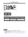
When using an RS-232C device as a peripheral device, caution will be required when connecting
and disconnecting the connector.
Always use a double-OFF type AC power supply switch on the device side, and connect/
disconnect the connector with the AC power supply on the device side OFF.
Device
NC unit
RS-232C
Switch
AC socket
FCU6-DX561 CONNECTION AND MAITENANCE MANUAL
CONTENTS
I. CONNECTION MANUAL
1. OUTLINE .....................................................................................................................
2. CONFIGURATION .......................................................................................................
2.1 System Configuration ..........................................................................................
3. INSTALLATION ...........................................................................................................
3.1 General Specification ..........................................................................................
3.2 Noise Countermeasures......................................................................................
3.2.1 Connection of FG (Frame Ground) ..............................................................
3.2.2 Shield Clamping of Cables...........................................................................
3.2.3 Connecting Spark Killers..............................................................................
3.3 Installation ...........................................................................................................
3.4 Mounting Conditions............................................................................................
4. SYSTEM CONNECTION..............................................................................................
4.1 General System Diagram ....................................................................................
5. CONNECTION OF UNIT..............................................................................................
5.1 Names of Each Part ............................................................................................
5.2 Unit Connection System Diagram .......................................................................
5.3 Connection of Base I/O Unit ................................................................................
5.4 Connection of RIO Unit .......................................................................................
5.5 Connection of Power Supply ...............................................................................
5.6 Connection of Encoder Speed Signal .................................................................
5.7 Connection of Machine Input/Output Signal ........................................................
APPENDIX 1 UNIT OUTLINE DRAWINGS AND INSTALLATION DIMENSIONS .........
APPENDIX 2 LIST OF CONNECTOR SETS...................................................................
APPENDIX 3 CABLE MANUFACTURING DRAWING ...................................................
Appendix 3.1 FCUA-R000 Cable Manufacturing Drawing ........................................
Appendix 3.2 FCUA-R211 Cable Manufacturing Drawing ........................................
Appendix 3.3 FCUA-R220 Cable Manufacturing Drawing ........................................
Appendix 3.4 R300 Cable Manufacturing Drawing...................................................
Appendix 3.5 R301 Cable Manufacturing Drawing...................................................
Appendix 3.6 R-TM Manufacturing Drawing.............................................................
APPENDIX 4 PRECAUTIONS FOR COMPLYING WITH UL/c-UL STANDARDS .........
I-1
I-2
I-2
I-3
I-3
I-4
I-4
I-5
I-6
I-7
I-8
I-9
I-9
I-10
I-10
I-11
I-12
I-13
I-14
I-15
I-17
I-21
I-22
I-23
I-25
I-26
I-27
I-28
I-29
I-30
I-31
II. MAINTENANCE MANUAL
1. EXPLANATION OF MODULE FUNCTIONS ................................................................
1.1 FX2N-80BMT-NC Card .......................................................................................
2. FAULT DIAGNOSIS.....................................................................................................
2.1 List of Unit LEDs..................................................................................................
2.2 Troubleshooting...................................................................................................
2.2.1 Confirmation of trouble state ........................................................................
2.2.2 When in trouble............................................................................................
2.2.3 Behavior of independent faults ....................................................................
3. DAILY MAINTENANCE AND PERIODIC INSPECTION AND MAINTENANCE .........
3.1 Maintenance Tools ..............................................................................................
3.2 Replacement Methods ........................................................................................
3.2.1 Cable............................................................................................................
3.2.2 Unit...............................................................................................................
II-1
II-1
II-3
II-3
II-4
II-4
II-5
II-9
II-10
II-10
II-11
II-11
II-13
I. CONNECTION MANUAL
1. OUTLINE
1. OUTLINE
This manual explains the items required for installing and connecting the remote I/O unit (FCU6-DX561).
The FCU6-DX561 is a remote I/O unit with PLC functions. This unit is used as to monitor both the
machine signals and the spindle speed.
Read this manual thoroughly and understand the product's functions and performance before starting
use.
Refer to the following documents for explanations on the functions.
FX2N Hardware Manual (JY992D66301G)
FX Programming Manual (JY992D88101A)
MELDAS AC Servo/Spindle MDS-C1 Series Specifications Manual (BNP-C3000)
Refer to the following material for details on EMC Directives for the European CE Marking.
EMC Installation Guideline (BNP-B2230)
I-1
2. CONFIGURATION
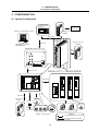
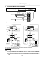
2.1 System Configuration
2. CONFIGURATION
2.1 System Configuration
Communication
terminal
Operation
panel, etc.
Ethernet communication device
Remote I/O unit
DX1
MC link B
Remote I/O unit
FCU6-DX561
Remote I/O unit
DX1
MC link A
M64:BASE-T or BASE-5
M65/66:BASE-T
M60/M600 Series control unit
MC
link B
CBUS 1 CBUS 2
OPEN
MC link
B
0
Base I/O unit
SKIP
CF10
Spindle drive unit
Power supply unit
Servo drive unit
Servo drive unit
MDS-B/C1-V1/V2- MDS-B/C1-SP- MDS-B/C1-CV-
MDS-B-SVJ2-
MDS-B-SPJ2- MDS-B-CVE-
MR-J2-CT (auxiliary axis)
0
0
ENC1
SV2
SV1
RI02 RI01
DCIN
MC link A
CR31
CF31 CF32
CF33 CF34
CF11
MITSU BISHI
MDS-B -SVJ2
RS232C
CH1、CH2
HANDL
CH1~CH3
MC link B
Remote I/O unit
DX1
Synchronous
feed encoder
Sensor
Synchronous
feed encoder
Manual pulse generator
RS-232C device
Max.
8 channels
Servomotor
Machine control signal
Spindle motor
Legend
: Connections described in this manual
: Connections described in separate
documents
I-2
3. INSTALLATION
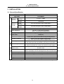
3.1 General Specification
3. INSTALLATION
3.1 General Specification
Unit name
Remote I/O unit
Type name
FCU6-DX561
Power specifications
General specifications
During
operation
Ambient
temperature During
storage
Ambient
humidity
0 to 55°C * Note
–20 to 60°C
During
operation
45 to 75% RH (with no dew condensation)
During
storage
45 to 80% RH (with no dew condensation)
4.9m/s2 or less (during operation)
Vibration resistance
Shock resistance
Working atmosphere
29.4m/s2 or less (during operation)
98m/s2 or less (during transportation)
No corrosive gases, or high levels of dust or oil mist
Power noise
1kVA (P-P)
Withstand voltage
500VAC for one minute
Across entire output terminal batch and grounding terminal
Insulation resistance
5MΩ or more with 500VDC megger tester
Across entire output terminal batch and grounding terminal
Grounding
Class D grounding
Use without grounding is possible if grounding is not possible.
Power voltage
24VDC +10%/−15%
(Must be insulated from 100VAC and 200VAC power supply)
Instantaneous stop
tolerance time
Operation continues when power instantaneously stops
for 4ms or less.
Power fuse
Chip type fuse incorporated
(SSTC 0.8A Maker: SOC UL198G approved, CSA C22.2 No. 59.2)
Power consumption
Approx. 10W (Only control section; excludes input/output section)
Rush current
Approx. 20A/1ms, approx. 5A/10ms
Sensor power
None
Weight
1.8kg
Unit size
Refer to Appendix.
* Note If the ambient temperature is 55°C or more, lower to 55°C or less with forced cooling.
I-3
3. INSTALLATION
3.2 Noise Countermeasures
3.2 Noise Countermeasures
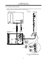
3.2.1 Connection of FG (Frame Ground)
The frame should basically be grounded at one ground point.
Connect the control unit and base I/O unit's and remote I/O unit's 0V (RG) to the FG on the 24VDC
stabilized power supply side.
Control unit
FCU6-MU
-MA
FG cable
0
R220 cable
(24VDC)
Remote I/O unit
FCU6-DX561
FG
FG
0V
DC24V
24VDC
(+)
(+)
Short bar
4
ST
No.
PU
ON
WER
R
C
PU-E
STOP
RUN
R220 cable
(24VDC)
AC input
Stabilized power supply
O
R
I
ERR1
ERR2
R220 cable
(24VDC)
Base I/O unit
FCU6-DX3/DX4/HR377/378
0
0
ENC
SKIP
CF10
SV2
SV1
CR31
CF31CF32
CF33 CF34
RIO2 RIO1 DCIN
FG
FG
0V
0V
DC24V
24VDC
(+)
(+)
Short bar
HR3□□
FG cable
AC input
FG cable
Stabilized power supply
Main gaounding plate
for electric cabinet
I-4
FG cable
3. INSTALLATION
3.2 Noise Countermeasures
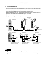
3.2.2 Shield Clamping of Cables
(1) Cables requiring ground connection with lead wire
The FG wire of the RIO cable (R211) connected between the base I/O and each remote I/O unit
must be connected to the grounding plate near the unit.
Remote I/O unit
FCU6-DX561
Base I/O unit
FCU6-DX3/DX4/HR377/378
0
Remote I/O unit
FCUA-DX1
0
ENC
SKIP
4
ST
No.
CF10
SV2
SV1
P
W
R
RO
U
NE
C
PU
-E
CR31
STOP
CF31 CF32
CF33 CF34
RUN
RIO2 RIO1
DCIN
HR3□□
X
X
Grounding plate
Grounding plate
O
R
I
ERR1
ERR2
FG wire
FG wire
X
X
FG wire FG wire
R211 cable
R211 cable
Grounding plate
(2) Cables which require shield clamp with connector cases
The shield of encoder cable (R000) for the speed signal input must be clamped with the connector
case.
<Shield clamp method>
Fold the cable shield on the sheath, and wrap copper foil tape over it.
Connect with the connector GND plate.
I-5
3. INSTALLATION
3.2 Noise Countermeasures
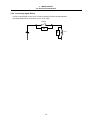
3.2.3 Connecting Spark Killers
Connect a spark killer on the coil or contact in parallel for noise countermeasures.
Use spark killers which are 0.033 to 0.1µF, 10 to 120Ω.
Contact
SK
SK
E
I-6
Coil
3. INSTALLATION
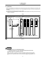
3.3 Installation
3.3 Installation
Each unit is installed in the sealed structure cabinet as a principle. When installing into the cabinet, refer
to the following drawings to consider the unit's heat dissipation and wiring, and secure enough space for
ventilation.
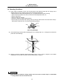
(1) Install the unit vertically so that the front is visible.
(2) Refer to the following drawings to consider the unit's heat dissipation and wiring, and secure enough
space for ventilation.
(Top)
50mm or more
100mm or more Control Remote I/O unit (heat dissipation Remote I/O unit
(FCU6-DX561) allowance)
(heat dissipation unit
(FCUA-DX1) Servo drive unit Spindle drive unit
allowance)
MITSU BISHI
MDS-B -SVJ2
MITSU BISHI
MDS-B -SVJ2
CBUS 1 CBUS 2
50mm
or more
30mm
or more
OPEN
4
ST No.
POWER
RUN
CPU-E
STO P
RU N
0
150mm or more
(heat dissipation,
wiringallowance)
RIO
ER R 1
ER R 2
10mm or more 10mm or more 10mm 15mm or more
15mm or more
100mm or more
or more (wiring allowance) (wiring allowance)
(heat dissipation,
wiring allowance)
(Bottom)
CAUTION
Install the unit on noncombustible material.
Installation directly on or near combustible material may lead to fires.
Always observe the installation direction.
Do not install or operate a unit that is damaged or that has missing parts.
The unit is a precision device so do not drop or apply strong impacts on it.
I-7
3. INSTALLATION
3.4 Mounting Conditions
3.4 Mounting Conditions
(1) Parts, highly susceptible to dust, are mounted with a high density inside the unit. Always use a
sealed structure for the cabinet, and provide the following treatments.
• Always plug the cable inlet with packing, etc., to prevent dust and oil from entering.
• Take care so that outdoor air does not enter the heat dissipation holes, etc.
• Plug all clearances.
• Always install door packing.
• If there is a back lid, always install packing.
• Oil will easily accumulate at the ceiling, and can enter the cabinet from the screw holes. Always
take special measures such as using oil-preventing packing.
Fitting
Cable
Packing
Cable inlet (Example)
(2) Avoid machining in the area after installing each unit. Cutting chips, etc., could get on the electronic
parts and cause damage.
(3) Design so that the cabinet's internal temperature rise is 10°C or less in respect to the outdoor
temperature, and so that it is within the unit's temperature conditions.
CAUTION
Do not allow conductive foreign matter such as screws or metal chips or combustible
foreign matter such as oil enter the unit.
I-8
4. SYSTEM CONNECTION
4.1 General System Diagram
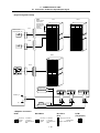
4. SYSTEM CONNECTION
4.1 General System Diagram
RST
3-phase 200VAC to 230VAC
Ethernet
communication device
BASE-T
No fuse breaker (NFB)
ON
Communication terminal
CT100/CT120/LD100/DUT32/DUN33
/EL10/CR10
OF F
RIO1 RIO2
MC link B terminator
R-TM
DCIN
MC
CR02
MC
CR05
CR01
In sert
when required
MC
R211
or
FG
FG
24VDC( +)
24VDC( +)
Stabilized
power supply
Operation
panel
Remote I/O unit
DX1
24VDC( +)
R211
To next remote
I/O unit
R000
FG
IC card
Power
supply
HR083
Control unit
M60/M600 Series
Op tion slot
RT2 RT1
CPU:HR114/146
OT rel ease switch
EMG
IC card: HR831
Ethernet: HR832
EMG
F120
RA
PLC unit
FCU6-DX561
Communication card
HR171
FG
AUX1 AUX2
24VDC
CF11
CF10
24VDC( +)
R220
DCIN
I/O link
24VDC (+)
Stabilized
power supply
R220
ENC1/
ENC2
To next
control unit
F050 F010
FG
FG
4
4
Machine control contact
CF11 CF10
24VDC( +)
MJ2
DC24IN
R000
SV1
Base I/O unit
HR377/HR378
FCU6-DX3 MJ3
FCU6-DX4
DI-L/
DI-R
Machine control relay
R
R
R
DO-L
R
RIO1RIO2
RIO1
MC1 MC1
or
R211
MC1
X axis and Y axis
MDS-B-SVJ2-∗∗
CN1A CN1B
L1
L2
L3
AC
servomotor
with detector
HC153TA33
SM
1.5kW
Detector
OSA253S
MC link B
Terminator
R-TM
SH21
Spindle encoder
SE1024-3-15-68
L11
L21
C
P
N
D
Regenerative
resistor
MR-RB
O30
CNV2/CNV12
cable
U
V
W
Spindle
MDS-B-SP-∗∗∗ Terminator
MDS-A-TM
CN1A CN1B
L1
L2
L3
CN8
L11
L21
Spindle motor
SJ-V15-02
7.5kW rating 30 min.
L11
L21
L1
U
V
W
L2
L+
L+
L-
L-
CN2
FG
F
G
FG
AC reactor B-AL
L1
L2
L3
CN6
IM
R211
To next remote
Converter
I/O unit
MDS-B-CV-∗
MDS-B-CVE-∗
MC1
Detector
CN5
CN4
MC1
CN4
R056 cable
(Note) This drawing is an example of the general connection for the M60/M600 Series. The actual
connection will differ according to the specifications.
I-9
5. CONNECTION OF UNIT
5.1 Names of Each Part
5. CONNECTION OF UNIT
The methods for connecting to each unit and device are briefly explained in this chapter.
Front view
5.1 Names of Each Part
DCIN (1)
DC IN
(1) 24VDC input connector
(2) Connector 1 for encoder (speed signal)
connection (Note)
(3) Connector 2 for encoder (speed signal)
connection (Note)
(4) Station No. setting rotary switch
(5) RUN-STOP slide switch
(6) Programming unit connection connector
(7) Digital signal input connector
(8) Digital signal input connector
(9) Digital signal output connector
(10) Remote I/O connection connector
(11) Remote I/O connection connector
ENC1 (2)
ENC1
ENC2
POWER
RUN
CPU-E
ST OP
RUN
PROG.
PORT
PROG.PORT (6)
4
3 5
B CD
RUN/STOP (5)
ST No.
8
67 9 A
ST No. (4)
0
EF 1 2
ENC2 (3)
DI-L (7)
DI-R
DI-L
DI-R (8)
(Note) The encoder speed signal is connected
via the spindle amplifier. As there is no
power supply, the encoder cannot be
directly connected to the connectors
ENC1/ENC2.
DO -L
DO-L (9)
RIO
ERR1
ERR2
Bottom view
RIO1
RIO2 (11)
RIO2
I-10
RIO1 (10)
5. CONNECTION OF UNIT
5.2 Unit Connection System Diagram
5.2 Unit Connection System Diagram
M60/M600 Series
control unit
Base I/O unit
R211 cable
F010 cable
CF10
CF10
CF11
RIO1
F050 cable
Additional
I/O card
HR211
CF11
24VDC
stabilized
power
R220 cable
DCIN
CS1 CS2
↑ ↑
0
1
Remote I/O unit
(FCU6-DX561)
RIO1
RIO2
ENC1
ENC2
DI-L
DI-R
DO-L
DCIN
R211 cable
R000 cable
R000 cable
R301 cable
R301 cable
R301 cable
Remote I/O unit or terminator (R-TM) Encoder (speed signal) 2 channels
Encoder (speed signal) 2 channels
DI
DI
DO
ST No.
↑
2
Name
RIO1
RIO2
ENC1
ENC2
DI-L
DI-R
DO-L
ST No.
Explanation
This is connected to the base I/O unit.
This is used to connect the terminator or to expand the remote I/O unit.
The remote I/O unit can be expanded by up to four stations.
Connected with encoder via spindle amplifier.
Connected with encoder via spindle amplifier.
DI: 28 (Sink/Source)
DI: 16 (Sink/Source)
DO: 32 (Source)
Set the station No. In the above example, "0, 1" is set for the base I/O, so set to "2". As this
unit occupies two stations, set this switch to an even number (0, 2, 4, 6).
(Note) If an odd number (1, 3, 5, 9) is set, the station number for when an even number
(0, 2, 4, 6) is set will be selected.
I-11
5. CONNECTION OF UNIT
5.3 Connection of Base I/O Unit
5.3 Connection of Base I/O Unit
The RIO1 connector is used for connection to the base I/O unit. Connect the R211 cable from the RIO1
connector on this unit to the RIO1 connector on the base I/O unit.
Control unit
(FCU6-MU/MA)
Remote I/O unit
(FCU6-DX561)
CBUS 1
CBUS 2
OPEN
4
ST
No.
POWER
RUN
CPU-E
STOP
RUN
DC IN
DC OUT
PS EMG
BAT ALM
ENC2
0
WD NC NC
ER LED SYS
NC
RST
CF10
CF11
F010 cable
F050 cable
ROI
ERR1
ERR2
Base I/O unit
FCU6-DX3/DX4
/HR377/378
SKIP
CF10
0
0
ENC1
X
X
SV2 SV1
CR31
CF31 CF32
CF33 CF34
R211 cable
CF11
未
使
用
RIO2 RIO1 DCIN
RS232C
CH1、CH2
HANDL
CH1~CH3
未
使
用
FG
(Front)
未
使
用
RIO2 RIO1 DCIN
カードアドオン用取付け穴(LG)
Bottom view
RIO1
R211 cable
R211 cable
RIO2
Terminator (R-TM)
(Back)
(Note) When not expanding the remote I/O
units, connect the terminator (R-TM) to
RIO2.
I-12
5. CONNECTION OF UNIT
5.4 Connection of RIO Unit
5.4 Connection of RIO Unit
The RIO2 connector is used to connect several remote I/O units. Connect the R211 cable from the RIO2
connector on this unit to RIO1 on the remote I/O unit.
When connecting several remote I/O units, connect the R211 cable from the RIO2 connector on the
remote I/O unit to the RIO1 connector on the next remote I/O unit.
Connect the terminator (R-TM) to the RIO2 connector on the final remote I/O unit.
When manufacturing the R211 cable, use the enclosed connector and contacts. If there are not enough
accessories, use the single-ended connector CN211 (option, single-ended).
(Refer to the cable manufacturing drawings for details.)
(Example for expanding remote I/O units)
Remote I/O unit
(FCUA-DX1)
(Front)
Remote I/O unit
(FCU6-DX561)
Bottom view
RIO1
RIO2
RIO2
RIO2
RIO2
RIO1
RIO1
R211 cable
R211 cable
X
Terminator (R-TM)
(Back)
(Front)
Remote I/O unit
(FCU6-DX561)
Bottom view
Remote I/O unit
(FCUA-DX1)
X
Bottom view
X
RIO1
RIO1
(Front)
X
Remote I/O unit
(FCUA-DX1)
(Front)
Bottom view
X
RIO1
RIO1
RIO2
RIO2
RIO2
RIO2
DCIN
DCIN
Terminator (R-TM)
Terminator (R-TM)
(Back)
(Back)
Connect the terminator (R-TM)
to RIO2 when not expanding
the remote I/O unit.
Connect the R211 cable from
RIO2 to RIO1 on the next
remote I/O unit.
(Back)
Connect the terminator (R-TM)
to RIO2 on the final unit.
CAUTION
Incorrect connections could damage the device, so always connect the cable to the
designated connector.
Do not connect or disconnect the connection cables between each unit while the power is
ON.
I-13
5. CONNECTION OF UNIT
5.5 Connection of Power Supply
5.5 Connection of Power Supply
Supply the 24VDC power supply for the control circuit to the DCIN connector (DCIN).
The 24VDC power for the input/output circuit is supplied from an external source. Supply to each
connector (DI-L/-R, DO-L).
Remote I/O unit
(1) DCIN power connection (for control circuit)
(FCU6-DX561)
Y
24VDC (+)
0V
FG
FG
DCIN
Stabilized power supply
(2) DI-L/-R power connection (for DI circuit)
(For source input)
4
3 5
0
EF 12
STNo.
BC D
24VDC (+)
0V
B4
B3
A4
A3
8
67 9 A
B4
B3
A4
A3
0V
ENC1
ENC2
DI-R
DI-L
POWER
RU N
CPU-E
STOP
RU N
PROG.
PORT
0V
FG
(For sink input)
DI-R
DI-L
+24V
24VDC (+)
+24V
B4
B3
A4
A3
DI-R
DI-L
B4
B3
A4
A3
0V
FG
DO-L
(3) DO-L power connection (for DO circuit)
(Fixed to source output)
DO-L
+24V
24VDC (+)
B4
B3
A4
A3
RI O
ERR1
ERR2
0V
FG
(Note) Connect the power or GND to all of the common pins on the DI-L/-R and DO-L connector.
CAUTION
Incorrect connections could damage the device, so always connect the cable to the
designated connector.
Do not connect or disconnect the connection cables between each unit while the power is
ON.
I-14
5. CONNECTION OF UNIT
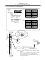
5.6 Connection of Encoder Speed Signal
5.6 Connection of Encoder Speed Signal
Encoder
1
10
ENC1
ENC1/2
(Note) Refer to
following
drawing.
20
11
<PCB side connector type>
Receptacle : 52822-4011
Maker
: Molex
<Cable side connector type>
Plug : 10120-3000VE
Shell : 10320-52F0-008
Recommended maker:
Sumitomo 3M
1
2
3
4
5
6
7
8
9
10
I
GND
PC1
GND
I
PC3
11
12
13
14
15
16
17
18
19
20
I
GND
PC1*
GND
I
PC3*
Connect the connector shell (frame) to
the FG via the pattern on the PCB.
ENC2
1
2
3
4
5
6
7
8
9
10
I
GND
PC2
GND
I
PC4
11
12
13
14
15
16
17
18
19
20
I
GND
PC2*
GND
I
PC4*
Connect the connector shell (frame) to
the FG via the pattern on the PCB.
PC3
PC3∗
Channel 3
DCIN
ENC1/2
PC4
ENC1ENC2
PC4∗
Channel 4
PC1
PC2
PC1∗
Channel 1
PC2∗
Channel 2
4
Station No.
setting
20
10
11
1
Encoder
OSE1024-3-15-68
STOP
RUN
Connector
ENC pin No.
DI-L
DI-R
CN8
CN6
R000 cable
Spindle amplifier
F040/F041 cable
DO-L
(Note) The encoder speed signal is connected via the spindle
amplifier.
As there is no power supply, the encoder cannot be
directly connected to the connectors ENC1/ENC2.
A dedicated cable is required to use channels 3/4 of the
connectors ENC1/ENC2.
I-15
5. CONNECTION OF UNIT
5.6 Connection of Encoder Speed Signal
[Outline of connection]
ENC1/2
PC
100Ω
1kΩ
PC∗
1kΩ
GND
Spindle
amplifier
[Signal assignment table]
1st channel
2nd channel
3rd channel
4th channel
X00
X01
X02
X03
[Input specifications]
Item
Input voltage
Input sensitivity
Input response time
Specifications
Line receiver input (X00 to X03) (5VDC)
OFF → ON 4.5mA or more, ON → OFF 1.5mA or less
X00 to X03 require 50µs or more for the second trigger to be validated.
The input pulse is detected at
Circuit insulation
.
Not insulated
CAUTION
Separate the signal wire from the drive line/power line when wiring.
Incorrect connections could damage the device, so always connect the cable to the
designated connector.
Do not connect or disconnect the connection cables between each unit while the power is
ON.
I-16
5. CONNECTION OF UNIT
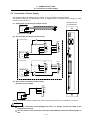
5.7 Connection of Machine Input/Output Signal
5.7 Connection of Machine Input/Output Signal
Machine input/output signal
types and number of points
Input
Output
44 points
32 points
R300 cable/
R301 cable
Number of occupied serial
link stations
2
DI-L
DI-R
Machine signal
R300 cable/
R301 cable
DO-L
Machine signal
[Outline of connection]
X00 to X07 and Y00 to Y37 below are indicated as octal values.
DI-L/R
DI_COM
A4
DI_24V
A4
B4
B4
A3
B3
A3
B3
DI_0V
Input circuit
sink type
DI_0V
DI-L/R
DI_COM
Input circuit
source type
DI_24V
3.3kΩ:4 points (X04 to X07)
4.3kΩ:40 points (X10 to X57)
3.3kΩ:4 points (X04 to X07)
4.3kΩ:40 points (X10 to X57)
DO-L
DO-L
DO_24V
DO_24V
DO_COM
A4
B4
A3
B3
A4
B4
A3
B3
DO_COM
Output circuit
source type
Output circuit
sink type
RA
RA
PL
DO_0V
DO_0V
Machine
control panel
Control
circuit
PL
Control
circuit
RIO1
RIO2
Machine
control panel
DCIN
24VDC (+) 0V
RIO2
DCIN
1 2 3
Stabilized
FG
power supply 24VDC (+) 0V
1 2 3
Stabilized
power supply
RIO1
FG
The input circuit can be switched to a sink type or source type with the connections.
The output circuit is fixed to the source type.
CAUTION
Incorrect connections could damage the device, so always connect the cable to the
designated connector.
Do not connect or disconnect the connection cables between each unit while the power is
ON.
I-17
5. CONNECTION OF UNIT
5.7 Connection of Machine Input/Output Signal
[Signal assignment table]
(Note)
DI-L
X00 to X03 are
used for the
encoder input,
and cannot be
assigned to
the DI-L
connector.
Machine side
control panel, etc.
DI-R
DI-L
B
DI-R
A
X20
X21
X22
X23
X04
X05
X24
X06
X07
X26
X10
X11
X12
X30
X13
X14
X33
X15
X16
X35
X17
DI_COM1
DI_COM1
X37
X25
X27
X31
X32
X34
X36
DI_COM1
DI_COM1
B
20
19
X40
18
17
X42
16
15
14
X44
13
12
X47
11
10
X51
9
8
7
X53
6
5
X56
4
3
DI_COM2
A
20
19
X41
18
17
X43
16
15
14
X45
X46
13
12
X50
11
10
X52
9
8
7
X54
X55
6
5
X57
4
3
DI_COM2
2
1
B
2
1
A
B
A
DO-L
A
B
Y00
Y01
Y02
Y03
Y04
Y05
Y06
Y07
Y10
Y11
Y12
Y13
Y14
Y15
Y16
Y17
DO_COM
DO_COM
DO-L
RA
PL
Y20
Y21
Y22
Y23
Y24
Y25
Y26
Y27
Y30
Y31
Y32
Y33
Y34
Y35
Y36
Y37
DO_COM
DO_COM
B
20
19
18
17
16
15
14
13
12
11
10
9
8
7
6
5
4
3
2
1
A
Base I/O unit
RI01
1
2
3
T X R X T X R X * LG
Remote I/O unit
RI02
2
1
3
T X R X T X R X * LG
DCIN
1
2
24VDC(+)
0V
24VDC (+)
X
D-3
0V
X
AMP
D-3
Y
AMP
D-3
AMP
R-TM
Remote I/O unit
<Adaptive connector>
DCIN
RIO1/RIO2
Connector : 2-178288-3
Contact : 1-175218-5
Maker
: Tyco Electronics
AMP
RI-L/DO-L
DI-R
Connector : 2-178288-3
Contact : 1-175218-5
Maker
: Tyco Electronics
AMP
I-18
Crimp type connector:
7940-6500SC
Maker: Sumitomo 3M
R-TM
(Terminator)
X
D-3
AMP
3
FG
5. CONNECTION OF UNIT
5.7 Connection of Machine Input/Output Signal
[Outline of input circuit]
The digital signal input circuit includes the sink type and source type. These can be selected with each
connector unit.
DI_24V
Connection method
Sink input
(X04 to X57)
<Octal notation>
680kΩ
DI_COM
X
X04 to X07:3.3kΩ 1/2W
X10 to X57:4.3kΩ 1/2W
DI_0V
Connection method
Source input
(X04 to X57)
<Octal notation>
X
DI_24V
680kΩ
DI_COM
DI_0V
X04 to X07:3.3kΩ 1/2W
X10 to X57:4.3kΩ 1/2W
[Input specifications]
Item
Input voltage,
current
Input sensitivity
Input response
time
Specifications
7mA/24VDC +10%, –15% (X04 to X07 sink/source changeover)
(External power supply)
5mA/24VDC +10%, –15% (X10 to X57 sink/source changeover)
(External power supply)
OFF → ON 4.5mA or more, ON → OFF 1.5mA or less
OFF → ON Approx. 4ms, ON → OFF Approx. 4ms (General input X20 to X57)
X00 to X17 are incorporated in the digital filter. (Can be changed to 0 to 60ms;
note that the minimum is 50µs) (Note)
X00 to X03 require 50µs or more for the second trigger to be validated.
The input pulse is detected at
Circuit insulation
.
Photo coupler insulation (* Excluding line receiver input)
(Note) The input filter value can be changed by rewriting the contents of the special data register
D8020 between 0 and 60 using the MOV command, etc. (The contents of D8020 are
automatically set to 10 (10ms) when the power is turned OFF and ON.)
D8020 value
0
10
to
60
Digital filter value
0ms
10ms
to
60ms
Note that in actual use, the minimum C-R filter is provided even on this input, and the value will
not be lower than 50µs (20µs for X00 to X01). Refer to the FX2N Hardware Manual for details.
I-19
5. CONNECTION OF UNIT
5.7 Connection of Machine Input/Output Signal
[Outline of output circuit]
The digital signal output circuit is a source type.
Connection method
Source output
(Y00 to Y37)
<Octal notation>
DO_24V
DO_COM
DO_0V
Y
[Output specifications]
Item
Rated voltage, current
Response time
Resistance load
Maximum
Inductive load
load
Lamp load
Output saturation voltage
Circuit insulation
Specifications (per point)
5VDC to 30VDC, 0.1A
0.2ms (at 24VDC, 0.1A energizing)
60mA (200mA for Y0 to Y3)
2.4W/24VDC (7.2W/24VDC for Y0 to Y3)
0.3W/24VDC (0.9W/24VDC for Y0 to Y3)
1.2V/0.1A
Photo coupler insulation
<Caution>
∗ When using an inductive load such as a relay, always connect a diode (voltage
resistance 100V or more, 100mA or more in reverse direction) in parallel to the
load. Note that the device will be damaged if the diode orientation is incorrect.
∗ When using a capacity load such as a lamp, always connect a protective
resistor (R = 150Ω) serially to the load to suppress rush currents. (Make sure
that the current is less than the above tolerable current including the
momentary current.)
CAUTION
When using an inductive load such as a relay, always connect a diode in parallel to the
load as a noise countermeasure.
When using a capacity load such as a lamp, always connect a protective resistor serially
to the load to suppress rush currents.
I-20
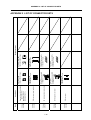
APPENDIX 1 UNIT OUTLINE DRAWINGS AND INSTALLATION DIMENSIONS
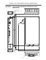
APPENDIX 1 UNIT OUTLINE DRAWINGS AND INSTALLATION
DIMENSIONS
50
10
To p
Heat
dissipation
allowance
2-M5x0.8 screw
DC IN
4
3 5
67 8 9 A
0
EF 12
ENC1
ENC2
ST No.
B CD
POWER
RUN
CPU-E
ST OP
RUN
380
360
PROG.
PORT
DI-R
DI-L
DO -L
10
30
60
Bottom
Heat dissipation,
wiring allowance 100
RIO
ERR1
ERR2
180
80
Wiring allowance
I-21
Application
Remote I/O unit (FCU6-DX561)
- Spindle amplifier
(MDS-B/C1-SP
)
MDS-B-SPJ2-
DIO connector - terminal block
I/O communication connector
24VDC power connector
DIO connector
Type
FCUACS000
FCUACS301
FCUACN211
FCUACN220
FCUACN300
3M
□ □
□ □
I-22
Connector (3M)
7940-6500SC × 2 pcs.
Connector
(Tyco Electronics AMP)
2-178288-3 × 1 pc.
Connector
(Tyco Electronics AMP)
1-178288-3 × 1 pc.
Connector (3M)
7940-6500SC × 4 pcs.
3M
Connector (3M)
10120-3000VE × 2 pcs.
Tin contact
(Tyco Electronics AMP)
1-175218-5 × 3 pcs.
Metal contact
(Tyco Electronics AMP)
1-175218-2 × 3 pcs.
Strain relief (3M)
3448-7940 × 2 pcs.
Connector case (3M)
10230-52F0-008 × 2 pcs.
Package contents
APPENDIX 2 LIST OF CONNECTOR SETS
APPENDIX 2 LIST OF CONNECTOR SETS
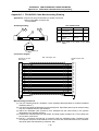
APPENDIX 3 CABLE MANUFACTURING DRAWINGS
APPENDIX 3 CABLE MANUFACTURING DRAWING
As a rule, most F/R cables used with this product are not sold by Mitsubishi. Thus,
manufacture the required cables using the cable manufacturing drawings on the following pages as a
reference. Note that the cable-compatible connectors can be purchased from Mitsubishi.
If crimp tools are not available when manufacturing the power supply cable (R200, R220) and
communication cable (R211), the cables can be manufactured by soldering a wire and connector as
shown in the following procedure.
1. Carry out preparatory soldering onto the wire.
(Peel 3.5mm of the sheath.)
2. Insert the wire into the contact. Hold
the sheath retainer.
Soldering iron
Contact
Wire
Solder
3. Lightly press down one side of the wire barrel
using radio pliers.
Wire barrel
This is a barrier to prevent
incorrect insertion. Do not bend.
4. Firmly press down the other side of the
wire barrel.
(Press firmly enough that the wire will
not come out when pulled lightly.)
Radio pliers
5. Firmly press down the sheath retainer in the
same manner as the wire barrel.
6. Apply the soldering iron, and melt the
preparatory solder inside.
Better results will be achieved if an
additional, small amount of solder is
applied.
Sheath retainer
Soldering iron
7. Lastly, insert the soldered contact with wire
into the housing.
Contact section
Be careful that the solder does not
flow into the contact section.
Pay attention to the insertion direction.
I-23
APPENDIX 3 CABLE MANUFACTURING DRAWINGS
<Cable type name table>
Appendix No.
Appendix 3.1
Appendix 3.2
Cable type
R000 cable
R211 cable
Encoder
Remote I/O
Application
: 2ch
Max. length
30m
Appendix 3.3
Appendix 3.4
Appendix 3.5
R220 cable
R300 cable
R301 cable
+24V input
DI/DO
DI/DO
Appendix 3.6
R-TM terminator
RIO unit communication terminator
Standard cable length
∗50m
30m
20m
20m
(Note 1) For the cable with an asterisk (∗) in the maximum cable length column, the total length (L1+ L2 + L3) of the cable length
(L1) from the control unit to the base I/O unit, the cable length (L2) from the base I/O unit to this unit, and the cable
length (L3) from this unit to each unit must be less than this value.
Maximum cable length
L1
F010
L2
Base I/O unit
Control unit
F050
Expansion
I/O unit
RIO1
R211
L3
Remote I/O unit
(FCU6-DX561)
DI-L/-R
DO-L
R300/
F301
RIO1
RIO2
R211
ENC1
ENC2
R000
Machine operation panel
Remote I/O unit
Servo amplifier
Encoder
(Note 2) Symbols for writing cable drawings
The following symbols are used in the cable drawings.
1.
indicates twist.
2.
indicates the shield sheath.
3.
indicates shield clamping to the ground plate.
4. In the cable drawings, the partner of the twisted pair cable is given a priority, so the pin Nos. of the connectors at both
ends are not necessary in number of order.
5. Equivalent parts can be used for the connector, contact and wire material.
I-24
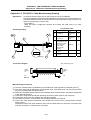
APPENDIX 3 CABLE MANUFACTURING DRAWINGS
Appendix 3.1 FCUA-R000 Cable Manufacturing Drawing
Appendix 3.1 FCUA-R000 Cable Manufacturing Drawing
Application: Remote I/O unit (FCU6-DX561) to spindle connection
Option (compatible connector set)
FCUA-CS000
Assembly drawing
List of parts used
No.
1 2
1 2
1
3
2
3
R000
Part name/model
Maker
Connector
Sumitomo 3M
10120-6000EL
Connector case
Sumitomo 3M
10320-3210-000
Wire material
Note (1)
UL20276
AWG28 × 10P
Qty.
2
2
(1)
(Note) This cable is the same as the SH21
cable.
R000
Note (3)
Connection diagram
Remote I/O unit side
ENC1/ENC2
Max. cable length: 30m
Spindle amplifier side
CN8
1
11
2
12
3
13
4
14
5
15
6
16
7
17
8
18
9
19
10
20
1
11
2
12
3
13
4
14
5
15
6
16
7
17
8
18
9
19
10
20
Case GND plate
Case GND plate
Manufacturing precautions
(1) The wire material shall be a shielded, 10-pair stranded cable equivalent to UL20276 Standard
AWG28 (0.08mm2).
(2) The parts used shall be Mitsubishi recommended parts. Equivalent parts may be used providing
they are compatible with the specifications.
(3) Attach the nameplate (with protective cover stamped with the cable name) in the position
designated in the assembly drawing.
(4) Fold the wire material shield over the sheath, and wrap copper foil tape over it. Then clamp with
the connector case frame.
(5) Part No. 1 (connector) and part No. 2 (connector case) are solderless types. If soldering types
are required, use parts 10120-3000VE for the connector and 10320-52F0-008 for the connector
case (both parts manufactured by Sumitomo 3M).
I-25
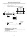
APPENDIX 3 CABLE MANUFACTURING DRAWINGS
Appendix 3.2 FCUA-R211 Cable Manufacturing Drawing
Appendix 3.2 FCUA-R211 Cable Manufacturing Drawing
Application:
Connection between base I/O unit and remote I/O unit (FCU6-DX561)
Connection between remote I/O unit (FCU6-DX561) and remote I/O unit (FCUA-DX1□□)
Connection between remote I/O unit (FCUA-DX1□□) and remote I/O unit (FCUA-DX1□□)
Option (corresponding connector set)
FCUA-CN211
(Note that when a single-end connector and contact are used, there is no crimp
terminal)
List of parts used
Assembly drawing
No.
Part name/type
Maker
Qty.
1
Connector
1-178288-3
2
Contact
1-175218-2
1 2
1 2
3
R211
3
4
R211
5
5
Note (3)
Wire material
MIX3CHRV-SV-SB
Twisted pair cable
with compound
3-pair shield
(TOA Electric
Industry)
Crimp terminal
V1.25-3
Crimp terminal
V1.25-5
Note (1)
2
6
(1)
J.S.T.
1
J.S.T.
1
4
Connection diagram
TXRX
TXRX*
LG
Tyco
Electronics
AMP
Tyco
Electronics
AMP
Max. cable length: 50m
1
2
3
1
2
3
FG
TXRX
TXRX*
LG
FG
Note (5)
Manufacturing precautions
(1) The wire material shall be a shielded 3-pair stranded pair cable equivalent to AWG20 (0.5mm2).
(2) The parts used shall be Mitsubishi recommended parts. Equivalent parts may be used providing
they are compatible with the specifications.
(3) Attach the nameplate (with protective cover stamped with the cable name) in the position designated
in the assembly drawing.
(4) Install each crimp terminal side after stamping the name of each signal on the mark tube.
(5) Protect both ends of the wire material with insulation bushing.
(6) Use AWG18 (0.75mm2) or equivalent for the shield treatment wire material.
(7) Ground the crimp terminal connected to the shield to the control unit or communication terminal
frame ground.
Note that to improve the noise resistance, there may be cases when only one end is connected, both
ends are connected, or neither end is connected.
I-26
APPENDIX 3 CABLE MANUFACTURING DRAWING
Appendix 3.3 FCUA-R220 Cable Manufacturing Drawing
Appendix 3.3 FCUA-R220 Cable Manufacturing Drawing
Application:
Supply of 24V to remote I/O unit (FCU6-DX561)
Option (compatible connector set)
FCUA-CN220
(Note that this corresponds only to the connector on the remote I/O unit side.)
List of parts used
No.
Assembly drawing
1
Connector
2-178288-3
2
Contact
1-175218-5
1 2
3
4
Part name/model
3
4
Maker
Tyco
Electronics
AMP
Tyco
Electronics
AMP
BANDO
Electric Wire
Note (1)
Wire material
JPVV-SB
2
1P × 0.5mm
Solderless terminal
J.S.T.
V1.25-3
Qty.
1
3
(1)
3
R220
R220
FG
Note (3)
GND
+24V
Connection diagram
Max. cable length: 30m
Remote I/O unit (FCU6-DX561) side
DCIN
Power supply side
WHITE
FG
GND
+24V
3
2
1
FG
GND
+24V
BROWN
Manufacturing precautions
(1) The wire material shall be a shielded 1-pair stranded cable equivalent to AWG20 (0.5mm2).
(If the cable length exceeds 10m, use AWG16 (1.25mm2).)
(2) The parts used shall be Mitsubishi recommended parts. Equivalent parts may be used providing
they are compatible with the specifications.
(3) Attach the nameplate (with protective cover stamped with the cable name) in the position designated
in the assembly drawing.
(4) Install each crimp terminal side after stamping the name of each signal on the mark tube.
(5) Protect both ends of the wire material with insulation bushing.
(6) Use AWG18 (0.75mm2) or equivalent for the shield treatment wire material.
I-27
APPENDIX 3 CABLE MANUFACTURING DRAWING
Appendix 3.4 R300 Cable Manufacturing Drawing
Appendix 3.4 R300 Cable Manufacturing Drawing
Application:
DIO – Machine electric cabinet
List of parts used
No.
1
2
Part name/model
Maker
Connector
Sumitomo 3M
7940-6500SC
Wire material
Note (1)
B40-S
Qty.
1
(1)
Assembly drawing
First wire is colored
Remote I/O unit
(FCU6-DX561) side
DI-L/-R
DO-L
1
Max. cable length: 20m
Machine electric cabinet side
3
R300
Note (2)
Manufacturing precautions
(1) The parts used shall be Mitsubishi recommended parts. Equivalent parts may be used providing
they are compatible with the specifications.
(2) Attach the nameplate (with protective cover stamped with the cable name) in the position designated
in the assembly drawing.
(3) The cable is the same for DI and DO. However, stamp DI or DO on the connector to prevent
incorrect insertion.
I-28
APPENDIX 3 CABLE MANUFACTURING DRAWING
Appendix 3.5 R301 Cable Manufacturing Drawing
Appendix 3.5 R301 Cable Manufacturing Drawing
Application:
DIO – Machine electric cabinet
List of parts used
No.
Part name/model
Maker
Connector
Sumitomo 3M
7940-6500SC
Strain relief
Sumitomo 3M
3448-7940
Wire material
Note (1)
B40-S
1
2
3
Qty.
2
1
(1)
Assembly drawing
First wire is colored
Remote I/O unit
(FCU6-DX561) side
DI-L/-R
DO-L
1
3
2
Max. cable length: 20m
1
Machine electric cabinet side
R301
Note (2)
Manufacturing precautions
(1) The parts used shall be Mitsubishi recommended parts. Equivalent parts may be used providing
they are compatible with the specifications.
(2) Attach the nameplate (with protective cover stamped with the cable name) in the position designated
in the assembly drawing.
(3) The cable is the same for DI and DO. However, stamp DI or DO on the connector to prevent
incorrect insertion.
I-29
APPENDIX 3 CABLE MANUFACTURING DRAWING
Appendix 3.6 R-TM Manufacturing Drawing
Appendix 3.6 R-TM Manufacturing Drawing
Application: Terminator for MC link B remote I/O unit (FCU6-DX561) termination
Assembly drawing
List of parts used
101 102
No.
1
103
D-3 AM P
1
2
3
2
Qty.
1
2
1
R- T M
3
Part name/model
Maker
Connector
Tyco
1-178288-3
Electronics
(X type)
AMP
Tyco
Contact
Electronics
1-175216-2
AMP
Resistor
KOA
100Ω 1/4W
Rear of
the connector
Connection diagram
R- TM
LG
3
TXRX*
2
100Ω
TXRX
1
Manufacturing precautions
(1) The parts used shall be Mitsubishi recommended parts. Equivalent parts may be used providing
they are compatible with the specifications.
(2) Cover the 100Ω terminator with a black insulation tube.
(3) Stamp the connector name "R-TM" in white on the rear of the connector.
I-30
APPENDIX 4 PRECAUTIONS FOR COMPLYING WITH UL/c-UL STANDARDS
APPENDIX 4 PRECAUTIONS FOR COMPLYING WITH UL/c-UL
STANDARDS
Observe the following matters to comply with the UL/c-UL Standards.
(1) Selecting the external 24VDC power supply unit
The remote I/O unit (FCU6-DX561) complies with UL Standards on the condition that the external
power supply unit for supplying 24VDC is a UL-approved part. Use a UL-approved part for the
power supply unit supplying 24VDC to this unit.
(2) Unit ambient temperature
The remote I/O unit (FCU6-DX561) complies with UL Standards on the condition that it is used
within the maximum ambient temperature given in "3.1 General Specifications" in Chapter 3 of this
manual.
Design so that the maximum ambient temperature of this unit does not exceed the temperature
given in "3.1 General Specifications" in Chapter 3 of this manual.
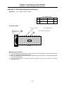
I-31
II. MAINTENANCE MANUAL
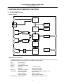
1. EXPLANATION OF MODULE FUNCTIONS
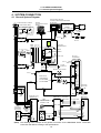
1.1 FX2N-80BMT-NC Card
1. EXPLANATION OF MODULE FUNCTIONS
1.1 FX2N-80BMT-NC Card
CN1
[Block diagram]
CPU
SW1
Run
EEPROM
BPU-G/A
SRAM
IO-G/A
DO I/F
DO-L
DC-DC
24V→5V
DCIN
ENC2
Stop
DI-L
ENC1
Encoder
I/F
DI-R
DI I/F
RIO2
IO-G/A
RIO1
RIO-G/A
[Explanation of functions]
The FX2N-80BMT-NC card is based on the MELSEC PLC FX2N Series, and has two remote I/O
controllers mounted. This functions as the remote I/O's slave station.
CPU
BPU-G/A
IO-G/A
Memory
RIO-G/A
I/O interface
Power supply
System control
PLC operation
External I/O interface
EEPROM
SRAM
Remote I/O controller
ENC1/2 connector
DI-L/-R connector
DO-L connector
RIO1/2 connector
DCIN connector
For ladder storage
Memory for execution
Occupies two stations
Encoder speed signal connection: 4ch
Input: 44 points
Output: 32 points
Remote IO slave station
Input: 24VDC +15%/−10% : 0.6A
II-1
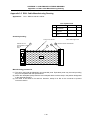
1. EXPLANATION OF MODULE FUNCTIONS
1.1 FX2N-80BMT-NC Card
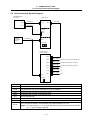
[Connector layout diagram]
RIO2
U:DI-R
L:DI-L
DCIN
SW2
POWER
RUN
CPU-E
U:ENC2
L:ENC1
DO-L
PROG.
PORT
RIOERR1
RIOERR2
RIO1
SW1
[Explanation of settings]
SW1
RUN-STOP slide switch
Starts running when the switch is set to RUN, and
stops when set to OFF.
SW2
Remote I/O station No.
setting rotary switch
0 to 7: Corresponds to the RIO station No. 0 to 7
(Set an even number)
8 and following: Loop back test mode (for testing)
(If the base I/O occupies 0 and 1, set the switch to 2.)
[Explanation of LEDs]
POWER
(Green) 5V power output
display
This turns ON when the state is normal.
RUN
(Green) Operation display
When the unit power is turned ON, the self-diagnosis
function activates. If there is no error, the operation
state is entered ("RUN" LED turns ON).
CPU-E
(Red) CPU error display
RIOERR1
(Red) Communication alarm in onboard RIO 0th station
RIOERR2
(Red) Communication alarm in onboard RIO 1st station
II-2
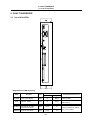
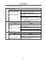
2. FAULT DIAGNOSIS
2.1 List of Unit LEDs
2. FAULT DIAGNOSIS
2.1 List of Unit LEDs
DCIN
ENC1
ENC2
0
EF 12
4
3 5
8
67 9 A
STNo.
BC D
POWER
RU N
CPU-E
STOP
RU N
PROG.
PORT
DI-R
DI-L
DO-L
RI O
ERR1
ERR2
[Explanation of LED functions]
Name
POWER
RUN
CPU-E
Function
Color
Status
When normal During error
5VDC output display
Green
Lit
Not lit
Operation display
Green
Lit
Not lit
Red
Not lit
Lit
Red
Not lit
Lit
Red
Not lit
Lit
CPU error display
Onboard I/O 1st station
RIOERR1
communication alarm
Onboard I/O 2nd station
RIOERR 2
communication alarm
II-3
Correspondence for error
24VDC +10%/−15%
Check the input
Check the RUN-STOP slide
switch setting
Refer to section 2.2.2.
Check the station No. setting
rotary switch setting
2. FAULT DIAGNOSIS
2.2 Troubleshooting
2.2 Troubleshooting
2.2.1 Confirmation of trouble state
Confirm "when", "when doing what", and "what kind of" trouble occurred.
(1) When?
What time did the trouble occur?
(2) When doing what?
What was the NC operation mode?
(3) What kind of trouble?
• What was displayed on the setting display unit's Alarm Diagnosis screen?
Display the Alarm Diagnosis screen, and check the alarm details.
• What was displayed for the machine sequence alarm?
• Is the CRT and LCD screen normal?
(4) How frequently?
• When did the trouble occur? What was the frequency? (Does it occur when other machines are
operating?) If the trouble occurs infrequently or if it occurs during the operation of another
machine, there may be an error in the power voltage or the trouble may be caused by noise, etc.
Check whether the power voltage is normal (does it drop momentarily when other machines are
operating?), and whether noise measures have been taken.
• Does the trouble occur during a specific mode?
• Does the trouble occur when the overhead crane is operating?
• What is the frequency in the same workpiece?
• Check whether the same trouble can be repeated during the same operation.
• Check whether the same trouble occurs when the conditions are changed.
(Try changing the override, program details, and operation procedures, etc.)
• What is the ambient temperature?
(Was there a sudden change in the temperature?
• Is there any contact defect or insulation defect in the cables?
(Has any oil or cutting water splattered onto the cables?)
II-4
2. FAULT DIAGNOSIS
2.2 Troubleshooting
2.2.2 When in trouble
If the system does not operate as planned or if there is any trouble in the operation, confirm the following
points and then contact the Mitsubishi Service Center.
− Examples of trouble −
•
•
•
•
•
•
•
•
The power does not turn ON.
The external power turns ON, but the control power does not turn ON.
The power turns OFF.
The communication alarm display "RIOERR1"/"RIOERR2" LED turns ON.
The 5VDC output display "POWER" LED turns OFF.
The CPU error display "CPU-E" turns ON (flickers).
The operation display "RUN" LED does not turn ON.
The load does not turn ON/OFF even though the corresponding output is turned ON or OFF in the
ladder monitor.
II-5
2. FAULT DIAGNOSIS
2.2 Troubleshooting
(1) Problems related to the power supply
The power does not turn ON.
Cause
The door interlock is applied.
Remedy
If the control panel door is not completely closed, close it. If
the door interlock is applied even when the door is closed,
the door interlock circuit is damaged.
The external power supply's input Check that the input voltage is within 200 to 230AC
voltage is not as specified.
+10%/–15%.
(Note) The power supply for this unit is 24VDC.
The external power supply is
faulty.
Check that the power can be turned ON with just the
external power supply.
(Note) Depending on the external power supply, the power
may not turn ON in the no-load state, so install a
slight load and check.
The external power turns ON but the NC control power does not turn ON.
Cause
Remedy
The external power supply output Disconnect the cable between the unit and the external
is not correct.
power supply, and check that the external power supply
output voltage is normal.
The power cable is disconnected
or broken.
There is a short circuit in the
configuration card.
Check the cable between the unit and external power
supply, and securely insert it.
Check that the cable is not broken, and replace if broken.
Check that no inductive foreign matter has entered the unit.
The power turns OFF.
Cause
Remedy
There is a problem in the supplied Check whether the voltage fluctuates at certain time zones.
power.
Check whether an instantaneous power failure has
occurred.
A problem occurs when the
Check whether the voltage drops instantaneously when the
peripheral device starts operating. peripheral device operation starts.
II-6
2. FAULT DIAGNOSIS
2.2 Troubleshooting
(2) Problems related to remote I/O unit (FCU6-DX561)
If any of the following problems occur, all points of the machine input/output data for the remote I/O
unit (FCU6-DX561) will turn OFF or may become unreliable. Thus, detect "Mismatch of input" with
the PLC for another unit (NC).
The communication alarm display "RIOERR1"/"RIOERR2" LED turns ON.
Cause
Remedy
The remote I/O cable (R211) is not Check the connection of the cable (R211) between the base
connected, is broken, or the
I/O unit and remote I/O unit (FCU6-DX561).
connector has a contact fault.
The remote I/O cable (R211) is
being affected by noise.
Separate the remote I/O cable (R211) from the drive line
and power line.
Always connect the FG wire to the grounding plate.
The station No. setting rotary
Change the base I/O unit, remote I/O unit (FCU6-DX561)
switch (SW2) setting is duplicated and other remote I/O unit (FCUA-DX1) station No. rotary
with another unit.
switch settings so that the station numbers are not
duplicated.
A fault has occurred in the internal Contact the Service Center and have the unit replaced.
circuit of the FX2N-80BMT-NC
card.
The 5VDC output display "POWER" LED turns OFF. (Or, the CPU-E LED lights for an instant.)
Cause
Remedy
The input power is not within the Check that the input voltage is +20V or less, and that the
tolerable range, or there is a fault voltage has not dropped for an instant. If the power is
in the internal 5V output
supplied correctly, contact the Service Center.
generation circuit.
The CPU error display "CPU-E" turns ON (flickers).
Cause
Remedy
If the CPU does not run properly
because inductive foreign matter
has entered or because of
abnormal noise from an external
source, or if the operation cycle
exceeds 200ms, the watch dog
timer error will occur and cause
this LED to turn ON.
If the watch dog timer error has occurred, error code 6105
will be stored when D8061 is monitored with a peripheral
device. Review the program to see whether the operation
cycle is too long. (Monitor D8012 to find the maximum
operation cycle.)
Note that if the problem is caused by any other factor, a
communication error will occur and online operations will not
be possible when a peripheral device is connected.
Check for the presence of an abnormal noise generation
source and for the entry of inductive foreign matter.
If this LED changes from a stable light to a flicker as a result
of the inspection, check the program. (Check for circuit
errors and syntax errors with the peripheral device's
program check function.)
If the "CPU-E" LED is still ON after completing all
inspections, contact the Service Center.
CAUTION
Do not apply voltages other than those indicated in this manual on the connector.
Doing so may lead to destruction or damage.
Incorrect connections may damage the devices, so connect the cables to the specified
connectors.
Do not connect or disconnect the connection cables between each unit while the power is
ON.
Do not connect or disconnect the PCBs while the power is ON.
II-7
2. FAULT DIAGNOSIS
2.2 Troubleshooting
The operation display "RUN" LED does not turn ON.
Cause
The RUN/STOP switch is set to
STOP.
Remedy
Set the RUN/STOP switch to RUN.
An error was detected by the unit's Check for circuit errors and syntax errors with the peripheral
self-diagnosis function.
device's program check function.
If the operation is stopped with a watch dog timer error, refer
to the section "The CPU error display "CPU-E" turns ON
(flickers)." on the previous page.
The load does not turn ON/OFF even though the corresponding output is turned ON or OFF in the ladder
monitor.
Cause
The relay output contact has
fused due to an overload, load
short-circuit or the rush current of
a capacity load, etc., or a contact
fault has occurred due to a rough
contact surface.
A fault has occurred in the
FX2N-80BMT-NC card output
circuit.
Remedy
If the error occurs even after the relay is replaced or the
cause of the relay output contact fusion is removed, contact
the Service Center.
Check whether there are any causes of overcurrent, such as
a load short-circuit.
Measure the output voltage with a tester. If the specified
voltage is not output, contact the Service Center and have
the unit replaced.
CAUTION
Do not apply voltages other than those indicated in this manual on the connector.
Doing so may lead to destruction or damage.
Incorrect connections may damage the devices, so connect the cables to the specified
connectors.
Do not connect or disconnect the connection cables between each unit while the power is
ON.
Do not connect or disconnect the PCBs while the power is ON.
II-8
2. FAULT DIAGNOSIS
2.2 Troubleshooting
2.2.3 Behavior of independent faults
The EN954-1 Category 3 machine system must be designed so that the safety functions are not
disabled when one of the safety-related parts fails independently. Precautions for the designs and
examples of the behavior when an independent fault occurs are listed below.
<Precautions for design>
Set a safety circuit outside the FCU6-DX561 so that the entire system works safely even if an
external power supply error or FCU6-DX561 fault, etc., occurs.
Detect a mismatch between PLCs or stop the machine system according to the behavior.
(1) Always configure circuits outside of the FCU6-DX561, such as an emergency stop circuit,
protection circuit, interlock circuit for reciprocating operations such as forward/reverse run, and
machine damage preventing interlock circuits such as positioning upper/lower limits.
(2) If the FCU6-DX561 CPU detects and error with a self-diagnosis function, such as a watch dog
timer error, all DO outputs will turn OFF. Output control may be disabled when errors occur at
sections, such as the input/output control section, which cannot be detected by the
FCU6-DX561 CPU.
Design an external circuit or mechanism so that the machine will operate safely in this case.
(3) The output may stay ON or may stay OFF depending on faults that occur in the output circuit's
photo coupler or transistor.
Design an external circuit or mechanism for the output signals that could lead to accidents so
that the machine will operate safely.
Example of behavior during independent fault occurrence
Cause of fault
Behavior
The 24VDC power for control turned OFF (failed). The PLC will stop.
The power cable was disconnected (broken).
The DO output will turn OFF.
The 24VDC power for DO turned OFF (failed)
The DO output will turn OFF.
The remote I/O cable was disconnected (broken). The RIO communication will stop.
(The communication alarm display "RIOERR1" or
The remote I/O cable is affected by noise.
"RIOERR2" LED will turn ON.)
The contact of the relay connected to DI fused, or Regardless of the machine signal's ON or OFF
a contact fault has occurred due to a rough
state, the DI input will turn OFF or ON.
contact surface.
The DI cable was disconnected (broken).
The DI input will turn OFF.
The contact of the relay connected to DI fused, or Regardless of the DO output's ON or OFF state,
a contact fault has occurred due to a rough
the relay will turn OFF or ON.
contact surface.
The DO cable was disconnected (broken).
The DO output will turn OFF.
The encoder failed.
The spindle amplifier's encoder I/F circuit failed.
The encoder input data will become an abnormal
value or will not be input.
The encoder cable between the encoder and
spindle amplifier was disconnected (broken).
The encoder input data will not be input.
(The encoder detection speed will become 0.)
The encoder cable between the spindle amplifier The encoder input data will not be input.
and FCU6-DX561 was disconnected (broken).
(The encoder detection speed will become 0.)
A watch dog timer error occurred in the
FCU6-DX561.
The PLC will stop, and the RIO communication will
stop.
The DO output will turn OFF.
(The CPU error display "CPU-E" will turn ON.)
A fault occurred in the internal 5V output
generation circuit.
The PLC will stop, and the RIO communication will
stop.
The DO output will turn OFF.
(The 5VDC output display "POWER" will turn
OFF.)
II-9
3. DAILY MAINTENANCE AND PERIODIC INSPECTION AND MAINTENANCE
3.1 Maintenance Tools
3. DAILY MAINTENANCE AND PERIODIC INSPECTION AND
MAINTENANCE
3.1 Maintenance Tools
(1) Measuring instruments
The following measuring instruments are used to confirm that the voltage is being supplied correctly
to the unit, to confirm that the wiring to the unit is correct, and to carry out simple troubleshooting.
Table 3.1 Maintenance tools
Tool
Condition
Tester
Application
To check that the wiring to the PLC unit is correct
before turning the power ON.
AC voltmeter
Measure the AC power voltage.
To measures the AC power voltage being supplied
The tolerable error is ±2% or less. to the external 24VDC power supply unit.
DC voltmeter
Max. scale 30V.
To measure the DC power voltage.
The tolerable error is ±2% or less. External power supply 24V (control section,
machine input/output interface)
Phase rotation
meter
To check the connection order of the AC 3-phase
input power supply.
Synchroscope
General measurement and simple troubleshooting
Note) Currently, a high-accuracy digital multi-meter is commonly used as a tester. This digital
multi-meter can be used as both an AC voltmeter and a DC voltmeter.
(2) Tools
Screwdriver (large, medium, small)
Radio pliers
II-10
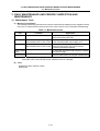
3. DAILY MAINTENANCE AND PERIODIC INSPECTION AND MAINTENANCE
3.2 Replacement Methods
3.2 Replacement Methods
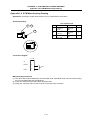
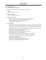
3.2.1 Cable
If the cable is replaced without turning the power OFF, the normal unit or peripheral devices could be
damaged, and risks could be imposed.
Disconnect each cable with the following procedures.
a) For the following type of connector, press the tabs with a thumb and forefinger in the direction of the
arrow, and pull the connector off.
(1) Press
(1) Press
Y
(2) Pull
(2) Pull
(1) Press
(2) Pull
CAUTION
Do not connect or disconnect the connection cables between each unit while the power is
ON.
Do not connect the cable by pulling on the cable wire.
II-11
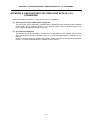
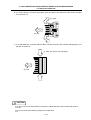
3. DAILY MAINTENANCE AND PERIODIC INSPECTION AND MAINTENANCE
3.2 Replacement Methods
b) For a flat cable type connector with claws, open the claws in the directions of the arrows, and pull
the connector off.
(1) Open
(2) Pull
c) For a flat cable type connector without claws, hold the connector with a thumb and forefinger, and
pull the connector off.
(1) Hold with thumb and forefinger.
(2) Pull
CAUTION
Do not connect or disconnect the connection cables between each unit while the power is
ON.
Do not connect the cable by pulling on the cable wire.
II-12
3. DAILY MAINTENANCE AND PERIODIC INSPECTION AND MAINTENANCE
3.2 Replacement Methods
3.2.2 Unit
Usually, the unit is installed on the electric cabinet side.
Always replace the unit with the machine power turned OFF.
1)
2)
3)
4)
5)
6)
Disconnect all cables connected to the unit.
Loosen screw A. (The screw does not need to be removed.)
While supporting the unit with a hand, remove screw B.
Lift the unit upward and remove it.
Replace with the new unit, and fix the unit with the fixing screw at the original position.
Reconnect the connected cables at the original positions.
(Connect the cables to the predetermined connectors.)
7) Check that all cables have been connected correctly, and then close the electric cabinet door.
Electric cabinet
Screw B
PLC unit
Fixing screw (two screws)
Screw A
Lift up
CAUTION
Incorrect connections may damage the devices, so connect the cables to the specified
connectors.
Do not replace the control unit while the power is ON.
Do not connect or disconnect the connection cables between each unit while the power is ON.
II-13
Revision history
Revision
Date of revision
∗
00/12/01
Revision details
First edition issued
MITSUBISHI ELECTRIC CORPORATION
HEAD OFFICE : MITSUBISHI DENKI BLDG., 2-2-3, MARUNOUCHI, CHIYODA-KU, TOKYO 100-8310, JAPAN
MODEL
REMOTE I/O UNIT・FCU6-DX561
MODEL
CODE
008-165
Manual No.
BNP-B2302* (ENG)
Specifications subject to change without notice.
(0110) MEE
Printed in Japan on recycled paper.