1
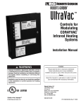
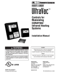
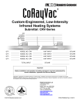
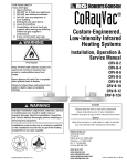
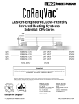
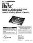
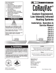
ROBERTS GORDON ® UltraVac ™ PATENTED Controls for Modulating CORAYVAC Infrared Heating Systems ® Installation Manual WARNING Improper installation, adjustment, alteration, service or maintenance can result in death, injury or property damage. Read the Installation, Operation and Service Manual thoroughly before installing or servicing this equipment. Installation must be done by an electrician qualified in the installation and service of control systems for heating equipment. © 2011 Roberts-Gordon LLC Installer Please take the time to read and understand these instructions prior to any installation. Installer must give a copy of this manual to the owner. Owner Keep this manual in a safe place in order to provide your serviceman with necessary information. Roberts-Gordon LLC 1250 William Street P.O. Box 44 Buffalo, New York 14240-0044 Telephone: +1.716.852.4400 Fax: +1.716.852.0854 Toll Free: 800.828.7450 www.rg-inc.com www.radiantheaters.com www.corayvac.com www.greenhouse-heater.com P/N 10081601NA Rev H 12/11 TABLE OF CONTENTS SECTION 1: Introduction........................................................ 2 1.1 Safety ........................................................................... 2 1.2 What is ROBERTS GORDON® ULTRAVAC™?............ 2 1.3 General Requirements ................................................. 2 1.4 CORAYVAC® Design Requirements............................. 2 1.5 Example Site Layout..................................................... 3 1.6 Check Installation Materials ......................................... 3 1.7 Safety Labels and Their Placement ............................. 3 1.8 Carton Contents ......................................................... 10 1.9 Standard Parts List..................................................... 13 SECTION 2: Specifications .................................................. 16 2.1 ROBERTS GORDON® ULTRAVAC™ Controller ....... 16 2.2 ULTRAVAC™ BMS Link Controller ............................ 16 2.3 NEMA 4 Enclosure (P/N 10080302) .......................... 16 2.4 Repeater .................................................................... 16 2.5 Temperature Sensors................................................. 16 2.6 Line Reactor 480 V / 4 A Output................................ 17 2.7 Variable Frequency Drive (VFD) ................................ 19 SECTION 3: Installation........................................................ 21 3.1 Preparation ................................................................ 21 3.2 Positioning the ROBERTS GORDON® ULTRAVAC™ Controller and Variable Frequency Drive ................... 21 3.3 Cable Requirements: ................................................. 22 3.4 Electrical Installation Requirements of ULTRAVAC™ Controller ................................................................... 22 3.5 Pump Requirements .................................................. 23 3.6 Variable Frequency Drive Requirements.................... 23 3.7 Indoor Sensor Placement .......................................... 24 3.8 Outdoor Sensor Placement ....................................... 24 3.9 Outside Air Supply ..................................................... 24 SECTION 4: Typical External Diagrams .............................. 25 SECTION 5: Communications.............................................. 30 5.1 Dedicated Phone Line for Central Controller Modem 30 5.2 RS-485 Converter for Central Controller.................... 31 5.3 TCP/IP Communication Module ................................ 32 5.4 Direct Connect ........................................................... 33 5.5 Communications Between Multiple ROBERTS GORDON® ULTRAVAC™ Controllers........................ 35 SECTION 6: ULTRAVAC™ BMS Link Controller ................. 38 6.1 ULTRAVAC™ BMS Link Controller Overview ............ 38 6.2 ULTRAVAC™ BMS Link Controller Requirements ..... 39 6.3 Technical Data ........................................................... 40 6.4 ULTRAVAC™ BMS Link Controller Programming...... 40 SECTION 7: Variable Frequency Drive Programming ........ 42 7.1 VFD Parameter Settings For Use With ROBERTS GORDON® ULTRAVAC™.......................................... 42 7.2 Altering VFD Parameters............................................ 43 SECTION 8: Commissioning The CORAYVAC® System .... 44 8.1 Setting The CORAYVAC® End Burner Vacuum ......... 44 SECTION 9: Troubleshooting .............................................. 48 SECTION 10: Replacement Parts ........................................ 55 10.1 ROBERTS GORDON® ULTRAVAC™ Controller Replacement Parts.................................................. 56 10.2 Variable Frequency Drive Replacement Parts ......... 57 10.3 ULTRAVAC™ BMS Link Controller Replacement Parts........................................................................ 58 10.4 Repeater Replacement Parts .................................. 59 10.5 Replacement Parts Instructions............................... 60 SECTION 11: The ROBERTS GORDON® ULTRAVAC™ Limited Warranty.......................................................... 62 There are references in this manual to various trademarks. All trademarks mentioned herein, whether registered or not, are the property of their respective owners. Roberts-Gordon LLC is not sponsored by or affiliated with any of the trademark or registered trademark owners, and make no representations about them, their owners, their products or services. Roberts-Gordon LLC is not sponsored by or affiliated with BACnet® or MODBUS®. © 2011 Roberts-Gordon LLC All rights reserved. No part of this work covered by the copyrights herein may be reproduced or copied in any form or by any means - graphic, electronic, or mechanical, including photocopying, recording, taping or information storage and retrieval systems - without the written permission of Roberts-Gordon LLC. Printed in U.S.A. TABLE OF FIGURES Figure 1: ULTRAVAC™ Controller Label Placement ................. 4 Figure 2: ULTRAVAC™ BMS Link Controller Label Placement 5 Figure 3: VFD Label Placement ................................................ 6 Figure 4: Repeater Label Placement ........................................ 7 Figure 5: Connected Components ............................................ 8 Figure 6: Example Site Layout ................................................ 15 Figure 7: ROBERTS GORDON® ULTRAVAC™ Controller Specifications .......................................................... 18 Figure 8: Variable Frequency Drive Components (Factory pre-wiring shown) ...................................... 20 Figure 9: Controller Mounting.................................................. 21 Figure 10: Variable Frequency Drive Mounting........................ 23 Figure 11: Indoor Sensor Mounting ......................................... 24 Figure 12: Outdoor Sensor Placement.................................... 24 Figure 13: ROBERTS GORDON® ULTRAVAC™ Central Controller External Wiring ...................................... 26 Figure 14: ROBERTS GORDON® ULTRAVAC™ Satellite Controller External Wiring ...................................... 28 Figure 15: Modem Location .................................................... 30 Figure 16: RS-485 PC Connection.......................................... 31 Figure 17: TCP/IP Communication Module Mounting ............. 32 Figure 18: TCP/IP Communication Module Wiring.................. 33 Figure 19: 9 Pin Adapter for PC .............................................. 34 Figure 20: Communications Between Multiple Controllers ..... 35 Figure 21: Repeater External Wiring ...................................... 36 Figure 22: Repeater Communication Wiring Between Multiple Controllers.............................................................. 37 Figure 23: Standard ULTRAVAC™ BMS Link Architecture ..... 38 Figure 24: ULTRAVAC™ BMS Link Controller Schematic ...... 39 Figure 25: Communication Between ULTRAVAC™ BMS Link Controller and Multiple ULTRAVAC™ Controllers .. 41 Figure 26: End Vent Vacuum .................................................. 45 Figure 27: Possible Damper Couplings’ Locations.................. 46 Figure 28: Troubleshooting Flow Chart ................................... 49 Figure 29: Troubleshooting Flow Chart - Repeater ................. 53 Figure 30: Troubleshooting Flow Chart - BACnet® .................. 54 Figure 31: ROBERTS GORDON® ULTRAVAC™ Controller Components Diagram ............................................ 56 Figure 32: Variable Frequency Drive Components Diagram ... 57 Figure 33: ULTRAVAC™ BMS Link Controller Components Diagram ................................................................. 58 Figure 34: Repeater Components Diagram ............................ 59 1 of 62 ROBERTS GORDON® ULTRAVAC™ CONTROLLER INSTALLATION MANUAL SECTION 1: INTRODUCTION 1.1 Safety Your Safety is Important to Us! This symbol is used throughout the manual to notify you of possible fire, electrical or burn hazards. Please pay special attention when reading and following the warnings in these sections. Installation, service and annual inspection of controller must be done by an electrician qualified in the installation and service of control systems for heating equipment. Installation, service and annual inspection of heater must be done by a contractor qualified in the installation and service of gas-fired heating equipment. ROBERTS GORDON® ULTRAVAC™, see Page 8, Figure 5. System status and settings are viewed and altered from a PC (not supplied) running ROBERTS GORDON® ULTRAVAC™ Software. 1.3 General Requirements DANGER Electrical Shock Hazard Read this manual carefully before installation, operation, or service of this equipment. Disconnect electric before service. The heater must be applied and operated under the general concepts of reasonable use. Controller must be properly grounded to an electrical source. This appliance is not intended for use by persons (including children) with reduced physical, sensory or mental capabilities, or lack of experience and knowledge, unless they have been given supervision or instruction concerning use of the appliance by a person responsible for their safety. Failure to follow these instructions can result in death or electrical shock. Children should be supervised to ensure that they do not play with the appliance. For optimum heater performance and safe heating conditions, inspect and maintain heater(s) before every heating season and as necessary. Also, know and maintain heater clearances to combustibles, see heater Installation, Operation and Service Manual for further details. If you require additional manuals, contact your ROBERTS GORDON® independent distributor or Roberts-Gordon at (716) 852-4400, (800) 828-7450 or at www.rg-inc.com. 1.2 What is ROBERTS GORDON® ULTRAVAC™? The ROBERTS GORDON® ULTRAVAC™ is a microprocessor based control package designed for modulating control of CORAYVAC® heaters based on outdoor temperatures. This controller is capable of giving control outputs to one vacuum pump and three heating zones. The controller also features inputs which are used for indoor and outdoor signal condition monitoring. For the overall view of connected components for 2 of 62 The ROBERTS GORDON® ULTRAVAC™ series of controllers are supplied pre-configured for use with ROBERTS GORDON® CORAYVAC® infrared heating equipment only. Failure to comply with the installation instructions and configuration may invalidate the ROBERTS GORDON® ULTRAVAC™ limited warranty. See Page 62, Section 11. ROBERTS GORDON® ULTRAVAC™ Software requires a PC (not supplied) running Windows® 95 or higher, with a Pentium® class processor and at least 64k of RAM. The controller, variable frequency drive, burners, repeater, pump and outside air blower must be electrically grounded in accordance with the National Electrical Code® ANSI/NFPA 70 - latest revision. Before proceeding with the installation of the controller, it will be necessary to check that the following points have been considered: 1.4 CORAYVAC® Design Requirements CORAYVAC® burners shall be CRV B-6, B-8, B-9, B-10 or B-12 burners. CORAYVAC® systems designed shall have minimum radiant pipe length and 1.5 - 2.0 feet per flow unit of tailpipe length. SECTION 1: INTRODUCTION -ORCORAYVAC® systems designed shall have recommended radiant pipe length and 1.2 - 1.5 feet per flow unit of tailpipe length. See the CORAYVAC® Design Manual (P/N 127500NA) for minimum and recommended radiant pipe length. ERTS GORDON® independent distributor to obtain replacement signs or labels. See Page 4, Figure 1 through Page 7, Figure 4. 1.5 Example Site Layout Page 15, Figure 6 is an example layout for a building where ROBERTS GORDON® ULTRAVAC™ will be used to control the infrared heating systems shown. The layout consists of three zones of ROBERTS GORDON® ULTRAVAC™. 1.6 Check Installation Materials 1.6.1 Switchable Loads The controller relays are rated for switching loads no greater than 3 A. The total added current load for all 8 relays must not exceed 25 A. 1.6.2 Control Wiring Shielded cable (four twisted pairs of stranded 24 AWG minimum wire) is required for use with indoor sensors. Shielded cable (one twisted pair of stranded 22 AWG minimum wire) is required for the outdoor air sensor, VFD signal wiring, pressure switch and wiring from controller #1 to the PC. Shielded cable (one twisted pair of stranded 22 AWG minimum wire) is required for RS-485 communications between controllers. 1.6.3 Control Board and Sensor Power The power supply for all sensors is from the “+32 V” terminal to be found on the board of the controller. Power for the control board is 24 V provided by the relay board. 1.6.4 Programming Details Every controller is pre-programmed for one pump and up to three heating zones. Use a site layout drawing to identify the heating zones. 1.7 Safety Labels and Their Placement Product safety signs or labels should be replaced by the product user when they are no longer legible. Please contact Roberts-Gordon LLC or your ROB3 of 62 ROBERTS GORDON® ULTRAVAC™ CONTROLLER INSTALLATION MANUAL FIGURE 1: ULTRAVAC™ Controller Label Placement Light Label Electrical Shock Hazard Label L2 GRD L2 POWER L1 GRD L2 OUTPUT 1 L1 GRD L2 OUTPUT 2 L1 GRD L2 GRD L2 OUTPUT 4 L1 GRD OUTPUT 5 L1 L2 GRD OUTPUT 6 L1 L2 GRD OUTPUT 7 L1 L2 GRD OUTPUT 8 L1 OUTPUT 3 L1 Logo Label Rating Plate Label Front Door Panel (outside) External Wiring Label NC C NO NC C NO L2 L1 PWR OUT IN G +32 +5 G G G REF + - NC C NO REF OUT 24VAC RS232 DIRECT AUX POWER + - + - + - + - + - NC C NO IN 4 3 2 1 METER INPUTS RS485 COMM RESET OH CD RI ADDRESS CPU NC C NO 7 6 UNIVERSAL INPUTS 5 4 3 - + - + - + - + - + - + - NC C NO 2 - + NC C NO 1 + 8 NC C NO OUT IN 499 OHM OFF ON 10VDC Front Door Panel (inside) Control Board Wiring Label 4 of 62 Description Logo Label Rating Plate Label Light Label Control Board Wiring Label External Wiring Label Shock Hazard label Part Number 91013207 91008005 91008007 91008004 91008003 91008001 SECTION 1: INTRODUCTION FIGURE 2: ULTRAVAC™ BMS Link Controller Label Placement Description Logo Label Rating Plate Label Light Label Control Board Wiring Label Shock Hazard label Part Number 91008017 91008016 91008015 91008014 91008001 5 of 62 ROBERTS GORDON® ULTRAVAC™ CONTROLLER INSTALLATION MANUAL FIGURE 3: VFD Label Placement Electrical Shock Hazard Label Side Panel (outside) Front Door Panel (outside) Rating Plate Label Variable Frequency Driver 1 Ø Input Model Shown B- Wiring Diagram Label U V W PE B+ Input Fuse Holder 17 PE 16 L2/N 1 2 5 6 11 13A 13B 13E 25 L1 Power Input Rotary Disconnect PE M16/12.P Relay 120 V Front Door Panel (inside) Description Rating Plate Label Wiring Label (230 V) Wiring Label (460 V) Shock Hazard label 6 of 62 Part Number 91008006 91008004 91008003 91008001 SECTION 1: INTRODUCTION FIGURE 4: Repeater Label Placement Description Wiring Diagram Label Logo Label Rating Plate Label Shock Hazard Label Part Number 91008020 91008021 91008022 91008001 7 of 62 ROBERTS GORDON® ULTRAVAC™ CONTROLLER INSTALLATION MANUAL FIGURE 5: Connected Components 8 of 62 SECTION 1: INTRODUCTION Connected Components (continued) 9 of 62 ROBERTS GORDON® ULTRAVAC™ CONTROLLER INSTALLATION MANUAL 1.8 Carton Contents URVSC: ULTRAVAC™ Satellite Controller ULTRAVAC™ Controller Line Voltage 120 V Wiring L1 POWER OUTPUT 1 OUTPUT 2 OUTPUT 3 OUTPUT 4 OUTPUT 5 OUTPUT 6 OUTPUT 7 OUTPUT 8 L2 GRD L1 L2 GRD L1 L2 GRD L1 L2 GRD L1 L2 GRD L1 L2 GRD L1 L2 GRD L1 L2 GRD L1 L2 GRD Low Voltage 24 V Wiring NC C NO L2 L1 PWR NC C NO OUT IN G +32 +5 G G G REF + - NC C NO REF OUT 24VAC RS232 DIRECT AUX POWER + - + - + - + - + - NC C NO IN 4 2 3 RS485 COMM 1 METER INPUTS RESET OH CD RI ADDRESS CPU 6 UNIVERSAL INPUTS 4 5 3 - + - + - + - + - + - + - NC C NO NC C NO 2 - + NC C NO 1 + 7 8 NC C NO OUT IN 499 OHM OFF ON 10VDC Inside View ULTRAVAC™ Installation Manual (P/N 10081601NA) URVCCL: ULTRAVAC™ Central Controller with TCP/IP Communication Module Line Voltage 120 V Wiring L1 POWER OUTPUT 1 OUTPUT 2 OUTPUT 3 OUTPUT 4 OUTPUT 5 OUTPUT 6 OUTPUT 7 OUTPUT 8 L2 GRD L1 L2 GRD L1 L2 GRD L1 L2 GRD L1 L2 GRD L1 L2 GRD L1 L2 GRD L1 L2 GRD L1 L2 GRD + - + - + - + 4 3 2 1 METER INPUTS RESET Modem Chip OH CD RI RESS Low Voltage 24 V Wiring NC C NO NC C NO L2 L1 PWR OUT IN G +32 +5 G G G REF + - NC C NO REF OUT 24VAC RS232 DIRECT + - + - + - + - + - NC C NO IN 4 3 RS485 COMM AUX POWER 2 1 METER INPUTS RESET OH CD RI ADDRESS CPU NC C NO 7 6 UNIVERSAL INPUTS 5 4 3 - + - + - + - + - + - + - Repeater (optional) Supplied w/24 VAC transformer inside NEMA 1 enclosure (P/N URVRP) NC C NO 2 - + ULTRAVAC™ Controller with Modem Installed NC C NO 1 + 8 NC C NO OUT IN 499 OHM OFF ON 10VDC 499 OHM Inside View Inside View ULTRAVAC™ Software (P/N 100816CDNA) contains: ULTRAVAC™ Software, ULTRAVAC™ Software Manual. (P/N 10081600NA) ULTRAVAC™ Installation Manual (P/N 10081601NA), BACnet® Software and Ruinet Manual. Outdoor Sensor (P/N 10081501) Kit, TCP/IP (LAN) Communication Module with PC Connection Cable Package (P/N 10080440K) Indoor Sensor (P/N 10081502) 10 of 62 SECTION 1: INTRODUCTION URVCCM: ULTRAVAC™ Central Controller with Modem Line Voltage 120 V Wiring L1 POWER OUTPUT 1 OUTPUT 2 OUTPUT 3 OUTPUT 4 OUTPUT 5 OUTPUT 6 OUTPUT 7 OUTPUT 8 L2 GRD L1 L2 GRD L1 L2 GRD L1 L2 GRD L1 L2 GRD L1 L2 GRD L1 L2 GRD L1 L2 GRD L1 L2 GRD + - + - + - + 4 3 2 1 METER INPUTS RESET Modem Chip OH CD RI RESS Low Voltage 24 V Wiring NC C NO NC C NO L2 L1 PWR OUT IN G +32 +5 G G G REF + - NC C NO REF OUT 24VAC RS232 DIRECT + - + - + - + - + - NC C NO IN 4 3 RS485 COMM AUX POWER 2 1 METER INPUTS RESET OH CD RI ADDRESS CPU NC C NO 7 6 UNIVERSAL INPUTS 5 4 3 - + - + - + - + - + - + - NC C NO 2 - + NC C NO 1 + 8 NC C NO OUT IN 499 OHM OFF ON 10VDC 499 OHM Inside View ULTRAVAC™ Controller with Modem Installed ULTRAVAC™ Software (P/N 100816CDNA) contains: ULTRAVAC™ Software, ULTRAVAC™ Software Manual. (P/N 10081600NA), ULTRAVAC™ Installation Manual (P/N 10081601NA), BACnet® Software and Ruinet Manual. Outdoor Sensor (P/N 10081501) Indoor Sensor (P/N 10081502) Repeater (optional) Inside View Supplied w/24 VAC transformer inside NEMA 1 enclosure (P/N URVRP) PC Connection Cable Package (P/N 10080410) 11 of 62 ROBERTS GORDON® ULTRAVAC™ CONTROLLER INSTALLATION MANUAL URVCCR: ULTRAVAC™ Central Controller with RS-485 Converter Line Voltage 120 V Wiring L1 POWER OUTPUT 1 OUTPUT 2 OUTPUT 3 OUTPUT 4 OUTPUT 5 OUTPUT 6 OUTPUT 7 OUTPUT 8 L2 GRD L1 L2 GRD L1 L2 GRD L1 L2 GRD L1 L2 GRD L1 L2 GRD L1 L2 GRD L1 L2 GRD L1 L2 GRD + - + - + - + 4 3 2 1 METER INPUTS RESET Modem Chip OH CD RI RESS Low Voltage 24 V Wiring NC C NO NC C NO L2 L1 PWR OUT IN G +32 +5 G G G REF + - NC C NO REF OUT 24VAC RS232 DIRECT + - + - + - + - + - NC C NO IN 4 3 RS485 COMM AUX POWER 2 1 METER INPUTS RESET OH CD RI ADDRESS CPU NC C NO 7 6 UNIVERSAL INPUTS 5 4 3 - + - + - + - + - + - + - NC C NO 2 - + NC C NO 1 + 8 NC C NO OUT IN 499 OHM OFF ON 10VDC 499 OHM Inside View ULTRAVAC™ Controller with Modem Installed ULTRAVAC™ Software (P/N 100816CDNA) contains: ULTRAVAC™ Software, ULTRAVAC™ Software Manual. (P/N 10081600NA), ULTRAVAC™ Installation Manual (P/N 10081601NA), BACnet® Software and Ruinet Manual. Outdoor Sensor (P/N 10081501) Inside View Repeater (optional) Supplied w/24 VAC transformer inside NEMA 1 enclosure (P/N URVRP) PC Connection Cable Package (P/N 10080410) RS-485 Converter Package (P/N 10080430) RS-485 Converter 12 of 62 Power Supply Indoor Sensor (P/N 10081502) SECTION 1: INTRODUCTION URVBNC: ULTRAVAC™ BMS Link Controller ULTRAVAC™ BMS Link Controller Inside View ULTRAVAC™ Software (P/N 100816CDNA) contains: ULTRAVAC™ Software, ULTRAVAC™ Software Manual. (P/N 10081600NA) ULTRAVAC™ Installation Manual (P/N 10081601NA),BACnet® or MODBUS® Software 1.9 Standard Parts List Table 1: Contents of ULTRAVAC™ Controller and Accessories Part No. URVCCL URVSC 10080142 10080440 10081501 10080410 10081502 URVCCM URVSC 10080142 1008150 10080410 10081502 URVCCR URVSC 10080142 10080430 1008150 10080410 10081502 URVBNC URVSC Description ULTRAVAC™ Central Controller (with TCP/IP Communication Module, Software & Manual), Including: Controller, ULTRAVAC™, 1 Pump 3 Zones (Satellite Control & Manual) Modem Chip TCP/IP Communication Module Outdoor Sensor PC Connection Cable Package Indoor Sensor (sold separately) ULTRAVAC™ Central Controller (with Modem Chip, Software & Manual), Including: Controller, ULTRAVAC™, 1 Pump 3 Zones (Satellite Control & Manual) Modem Chip Outdoor Sensor PC Connection Cable Package Indoor Sensor (sold separately) ULTRAVAC™ Central Controller (with RS-485 Converter, Software & Manual), Including: Controller, ULTRAVAC™, 1 Pump 3 Zones (Satellite Control & Manual) Modem Chip RS-485 Converter with 9V Power Supply Outdoor Sensor PC Connection Cable Package Indoor Sensor (sold separately) ULTRAVAC™ ULTRAVAC™ BMS Link Controller (with Software CD & Manual, IOS Manual) Controller, ULTRAVAC™, 1 Pump 3 Zones (Satellite Control & Manual) 13 of 62 ROBERTS GORDON® ULTRAVAC™ CONTROLLER INSTALLATION MANUAL Table 2: Common Components of ROBERTS GORDON® ULTRAVAC™ Controls Part No. Description Variable Frequency Drives* VFD75115 Variable Frequency Drive Assembly, .75 HP 115 V 1 Ø Input VFD75230 Variable Frequency Drive Assembly, .75 HP 230 V 1 Ø Input VFD20230 Variable Frequency Drive Assembly, 2 HP 230 V 1 Ø Input VFD75115N4 Variable Frequency Drive Assembly, .75 HP 115 V 1 Ø Input, NEMA 4 VFD75230N4 Variable Frequency Drive Assembly, .75 HP 230 V 1 Ø Input, NEMA 4 VFD75460 Variable Frequency Drive Assembly, .75 HP 480 V 3 Ø Input VFD75460N4 Variable Frequency Drive Assembly, .75 HP 480 V 3 Ø Input, NEMA 4 VFD20230N4 Variable Frequency Drive Assembly, 2 HP 230 V 1 Ø Input, NEMA 4 VFD20460 Variable Frequency Drive Assembly, 2 HP 480 V 3 Ø Input VFD20460N4 Variable Frequency Drive Assembly, 2 HP 480 V 3 Ø Input, NEMA 4 *NEMA 4 VFDs are special order items. Call for availablity. NEMA4 Enclosures** 10080302 Enclosure, NEMA 4 for URV Controller 10081510 Enclosure, NEMA 4 for URV Sensor **Enclosures only. Controller and/or Sensor must be purchased separately. Related Accessories 10080142 Modem, Plug-In Chip 10080410 Cable Package, PC Connection 10080430 RS-485 Converter with 9 V Power Supply 10080440 TCP/IP Communication Module 10080600 Telephone Sharing Device, 4-Port 10081500 Sensor, Adjustable Indoor, °F, URV 10081501 Sensor, Outdoor, URV 10081502 Sensor, Adjustable Indoor, °C, URV 90602450 Voltage Surge Supresser 90602460 Load Reactor 180 V / 4 A Output 90602470 Line Reactor 180 V / 4 A Input URVRP Repeater, URV Communication 14 of 62 Zone 1 Sensor Zone 1 Zone 2 Sensor Zone 2 ROBERTS GORDON® ULTRAVAC Controller Variable Frequency Drive Pump Zone 3 Outside Sensor Zone 3 Sensor North Wall SECTION 1: INTRODUCTION FIGURE 6: Example Site Layout NOTE: Conceptual drawing, not to scale. Venting not shown. 15 of 62 ROBERTS GORDON® ULTRAVAC™ CONTROLLER INSTALLATION MANUAL SECTION 2: SPECIFICATIONS 2.1 ROBERTS GORDON® ULTRAVAC™ Controller 2.1.1 Standard Enclosure Construction: 16 gauge painted steel, hinged door, removable knockouts provided. Dimensions: WxHxD (in): 14.7 x 17.7 x 3.5 (cm): 37.3 x 45.0 x 8.9 2.1.2 Electrical Power Supply: 120 V (+/- 10%) 1 Ø, 60 Hz UL Standard: UL 916 / C22.2 No. 205-M1983 Universal Inputs: Eight Universal Inputs Thermistor 0-10 Vdc 4-20m A Resistance Dry contact Link Controller. Standard enclosures are field mounted inside the NEMA 4 enclosure. Construction: 14 gauge painted steel, hinged door with 19" (48.3 cm) x (40.6 cm) 16" window. Dimensions: Protection Rating: Digital Outputs: Eight Digital Output: Single Pole 3 A 120 Vac Ports: RS-485 Communications Bus RS-232 Direct Connect Bus RS-232 Modem Socket 2.2 ULTRAVAC™ BMS Link Controller 2.2.1 Standard Enclosure Construction: 16 gauge painted steel, hinged door, removable knockouts provided. WxHxD (in):14.7 x 17.7 x 3.5 (cm): 37.3 x 45.0 x 8.9 2.2.2 Electrical Construction: Fabricated in accordance with UL specifications from code gauge steel, NEMA 1. Finish: Ports: RS-485 Communications Bus Ethernet/IP 2.3 NEMA 4 Enclosure (P/N 10080302) Description: 16 of 62 NEMA 4 enclosure is sold separately as an option, for ULTRAVAC™ Controller and ULTRAVAC™ BMS Austin screw cover boxes standard construction galvanized steel with ANSI 61 gray polyester powder coating. Dimensions: WxHxD (in): 12 x 12 x 4 (cm): 30.5 x 30.5 x 10.5 2.4.2 Electrical Power Supply: 120 V (+/- 10%) 1 Ø, 60 Hz Ports: RS-485 Communications Bus RS-232 Direct Connect Bus 2.5 Temperature Sensors Indoor Sensor Dimensions: WxHxD (in): 2.75 x 4.5 x 1.15 (cm): 7.0 x 11.4 x 2.9 Power: 32 V DC Dimensions: Power Supply: 120V (+/-10%) 1 Ø, 60 Hz NEMA 4, 12 2.4 Repeater 2.4.1 Standard Enclosure Analog Output: One Analog Output 0-10 Vdc Digital Inputs: Digital Inputs: Timed, dry contact WxHxD (in): 24 x 24 x 9 (cm): 61.0 x 61.0 x 22.9 Operating Temperature Range: 32° to 158° F (0° to 70° C) Features: LCD temperature display, setpoint adjustment, override button Outdoor Sensor (P/N 10081501) Dimensions: WxHxD (in): 1.4 x 5.3 x 2 (cm): 3.6 x 13.5 x 5.1 Operating Temperature Range: -40° to 221° F (-40° to 5° C) SECTION 2: SPECIFICATIONS Enclosure: NEMA 4 gasketed aluminum LB housing, ½" threaded connection NEMA 4 Enclosure for Indoor Sensor (P/N 10081510) Description: NEMA 4 Enclosure is sold separately as an option. The indoor sensor is field mounted inside the NEMA 4 enclosure. Temperature thermistor and LCD temperature display will not operate properly inside the enclosure. LCD display feature should be disabled and use of the NEMA 4 sensor enclosure will require the use of an outdoor sensor (P/N 10081501) in the space to monitor zone temperature. Dimensions: WxHxD (in): 6.3 x 3.6 x 1.8 (cm): 16.0 x 9.1 x 4.6 Voltage Surge Suppressor 277 / 480 V Construction: NEMA 2X Enclosure Volts: 277 / 480 V Frequency: 50/60 Hz Wiring Size: #12 AWG Standard Wire Construction: Polycarbonate enclosure with clear front cover, 4 screw cover closure. 16 gauge galvanized subpanel. Protection Rating: NEMA 4, 4X Flammability Rating: UL-94-5V 2.6 Line Reactor 480 V / 4 A Output Construction: Fabricated in accordance with UL specifications from code gauge steel, NEMA 1. Dimensions: WxHxD (in): 10 x 8 x 8 (cm): 25 x 20 x 20 Rated Current: 4A Volts: 480 V / 3 Ø Line Reactor 480 V / 4 A Input Construction: Fabricated in accordance with UL specifications from code gauge steel, NEMA 1. Dimensions: WxHxD (in): 10 x 8 x 8 (cm): 25 x 20 x 20 Rated Current: 4A Volts: 480 V / 3 Ø 17 of 62 ROBERTS GORDON® ULTRAVAC™ CONTROLLER INSTALLATION MANUAL FIGURE 7: ROBERTS GORDON® ULTRAVAC™ Controller Specifications Note: To ensure robust control signaling: Do not run line voltage wiring through bottom section of enclosure that houses the control board. Do not run low voltage wiring through top section of enclosure that houses the relay board. 18 of 62 SECTION 2: SPECIFICATIONS 2.7 Variable Frequency Drive (VFD) 2.7.1 Enclosure Standard Models Construction: 14 gauge painted steel, mounting panel included, left-hinged door, vented. Dimensions: WxHxD (in): 12 x 14.375 x 8 (cm): 30.5 x 36.5 x 20.3 Protection: UL 50 Type 1, NEMA Type 1 NEMA 4 Models Description: Drive assembly and components fully factory assembled inside NEMA 4 enclosure. Enclosure dimensions and construction vary by model. Construction: VFD75115N4, VFD20230N4 and VFD20460N4 enclosures are 16 gauge painted steel, left hinged door, non-vented. VFD75230N4 and VFD75460N4 enclosures are 14 gauge steel, left hinged door, non-vented. Dimensions: WxHxD VFD75115N4 (in): 20 x 16 x 10 (cm): 50.8 x 40.6 x 25.4 VFD75230N4 (in): 14 x 12 x 8 (cm): 35.6 x 30.5 x 20.3 VFD20230N4 (in): 20 x 16 x 10 (cm): 50.8 x 40.6 x 25.4 .75 HP, 230 V Drive (used with EP-203 pump) (P/N VFD75230 or VFD75230N4) Power Input: 208/230 V, 1 Ø, 50-60 Hz Input Voltage Tolerance: +/- 10% Amps: 6.9/6.0 A 1 HP, 120 V Drive (used with EP-203 pump) (P/N VFD75115 or VFD75115N4) Power Input: 120 V, 1 Ø, 50-60 Hz Input Voltage Tolerance: +/- 10% Amps: 16.6 A 2 HP, 230 V Drive (used with EP-303 pump) (P/N VFD20230 or VFD20230N4) Power Input: 208/230 V, 1 Ø, 50-60 Hz Input Voltage Tolerance: +/- 10% Amps: 18.4/16.0 A 1 HP, 460 V Drive (used with EP-203 pump) (P/N VFD75460 or VFD75460N4) Power Input: 400/480 V, 3 Ø, 50-60 Hz Input Voltage Tolerance: +/- 10% Amps: 3.0/2.5 A 2 HP, 460 V Drive (used with EP-303 pump) (P/N VFD20460 or VFD20460N4) Power Input: 400/480 V, 3 Ø, 50-60 Hz Input Voltage Tolerance: +/- 10% Amps: 4.8/4.0 A VFD75460N4 (in): 16 x 14 x 10 (cm): 40.6 x 35.6 x 25.4 VFD20460N4 (in): 20 x 16 x 10 (cm): 50.8 x 40.6 x 25.4 Protection: NEMA 3R, 4, 12, 13 2.7.2 Electrical Power Output: 230 V, 3 Ø, 0-60 Hz (for 115 V and 230 V models) 480 V, 3 Ø, 0-60 Hz (for 480 V models) Speed Reference Follower: 0-10 Vdc or 4-20 mA UL Standard: Industrial Controls Equipment Ambient Operating Temp.: 32° F - 104° F (0° C - 40° C) 19 of 62 ROBERTS GORDON® ULTRAVAC™ CONTROLLER INSTALLATION MANUAL FIGURE 8: Variable Frequency Drive Components (Factory pre-wiring shown) 20 of 62 SECTION 3: INSTALLATION SECTION 3: INSTALLATION DANGER Electrical Shock Hazard Disconnect electric before service. Controller must be properly grounded to an electrical source. Failure to follow these instructions can result in death or electrical shock. Installation of the ROBERTS GORDON® ULTRAVAC™ Controller and the associated external electrical wiring must be done by an electrician qualified in the installation of control systems for heating equipment. 3.1 Preparation maximum ambient temperature does not exceed 104°F (40°C). Avoid installing the VFD in mezzanines, direct sunlight, or near external heat sources because these locations usually have unpredictable temperature rises. Note that the maximum distance from the controller to any sensor is 300' (120 m). For longer distances, larger gauge wire may be needed (Consult your local distributor). For multiple controllers, maximum length of communication wire from the first controller to the last is 4000' (1219 m) without the use of a repeater. A repeater is available for wire length greater than 4000' (1219 m). See Page 36, Section 5.5.1. Wiring between the RS-485 converter to the controller should not be more than 400' (122 m) in length. See Page 31, Section 5.2. 3.2.2 Position the controller and VFD at occupant level for ease of service. To avoid electrical interferences with communications bus, do not mount VFD directly next to controller. Allow 2' (.6 m) minimum between controller and VFD. If the VFD is more than 100' (150 m) from the pump a load reactor (P/N 90602460) must be used. FIGURE 9: Controller Mounting Before installing the controller, observe the following: (Standard enclosure only, NEMA 4 enclosure mount3.1.1 Ensure that you have a copy of the site layout ing varies) for the project that clearly identifies the separate zones. 3.1.2 Familiarize yourself with the Controller and Variable Frequency Drive component names and locations. See Page 18, Figure 7 and Page 20, Figure 8. 3.2 Positioning the ROBERTS GORDON® ULTRAVAC™ Controller and Variable Frequency Drive 3.2.1 Choose a mounting location for the controller. For serviceability, it is convenient to mount the controller and variable frequency drive at occupant level in the vicinity of the pump. The variable frequency drive should not be more than 50' (15 m) from the pump. Do not mount controller or VFD outdoors. VFD must not be installed where subjected to adverse conditions such as: combustible, oily, or hazardous vapors or dust; excessive moisture or dirt; vibration. To avoid damage from possible drips, do not mount controller or VFD directly beneath pump. Models with NEMA 4 rated enclosures will withstand exposure to dust, dirt and water. 16.25" (41.3 cm) 13" (33 cm) VFD should be mounted in locations where the 21 of 62 ROBERTS GORDON® ULTRAVAC™ CONTROLLER INSTALLATION MANUAL 3.3 Cable Requirements: As per individual building specification for class of cable to be used. Use copper conductors only. 3.3.1 ULTRAVAC™ Controller Below is the recommended cable for the various connections for ULTRAVAC™ Controller: • Line Power Supply The power connection should be made with cable, size 14 AWG. • Eight Digital Output (Relays) The control connection for load of each individual relay should be made with cable, size 16 AWG. • Digital Input The wiring connection for the pressure switch should be unshielded cable, size 18 AWG. • Indoor Sensor Cable a) Shielded cable - Four twisted pairs of stranded, 24 AWG minimum or equivalent Madison Cable #08CFJ00004; Belden #9681. b) Unshielded cable - Four twisted pairs of stranded, 24 AWG minimum or equivalent AMP#219538, #219513; Belden#1585, #1583A. • Outdoor Sensor Cable Shielded cable - One twisted pair of 22 AWG minimum or equivalent Belden #8451, #1503A; General Cable #C2514. • Communications between Multiple Controllers (RS-485) One twisted pairs of 18 AWG minimum or equivalent shield cable; Belden #1902, General Cable #C1670A. VFD75230 or VFD75230N4 14 AWG VFD20230 or VFD20230N4 12 AWG VFD75460 or VFD75460N4 14 AWG VFD20460 or VFD20460N4 14 AWG • VFD(0-10 Vdc) Speed Reference Control Wiring Shielded cable - one twisted pair of 22 AWG minimum or equivalent Belden #8451, #1503A; General Cable #C2514. 3.3.4 Repeater Below is the recommended cable for the various connections for the repeater: • Line Power Supply The power connection should be made with cable, size 18 AWG. • RS485 Communications Multiple repeaters may be installed on the main loop and all communications cable should be made with shielded cable one twisted pair of 18-22 AWG. 3.4 Electrical Installation Requirements of ULTRAVAC™ Controller DANGER Electrical Shock Hazard Disconnect electric before service. 3.3.2 ULTRAVAC™ BMS Link Controller Below is the recommended cable for the various connections for ULTRAVAC™ BMS Link Controller: • Line Power Supply The power connection should be made with cable, size 18 AWG. • Communications between ULTRAVAC™ BMS Link and Multiple Controllers One twisted pair of 22 AWG minimum or equivalent shield cable; Belden #1902, General Cable #C1670A. 3.3.3 Variable Frequency Drive (VFD) Below is the recommended cable for the various connections for VFD: • Line Power Supply Input Wire Size Requirements VFD P/N Wire Size VFD75115 or VFD75115N4 12 AWG 22 of 62 Controller must be properly grounded to an electrical source. Failure to follow these instructions can result in death or electrical shock. • ULTRAVAC™ Controller must be feeding from a local fused isolator for a total amperage not exceeding 25 A. • Eight digital outputs for each individual relay must not exceed 3 A. NOTES: • The total added current load for each individual relay must not exceed 3 A. • The total added current load for all 8 relays must not exceed 25 A. SECTION 3: INSTALLATION 3.5 Pump Requirements The pump is powered directly from the Variable Frequency Drive (VFD). The VFD will be energized via an output from the relay board switched through a designated relay. 3.6 Variable Frequency Drive Requirements The VFD must be powered separately from the control enclosure. The 230 V drive power supply must be 230 V, 50-60 Hz, 1 Ø. The 120V drive power supply must be 120 V, 50-60 Hz, 1 Ø. The 480 drive power supply must be 480 V, 50-60 Hz, 3 Ø. See Page 19, Section 2.7 for additional details. The VFD on/off switching is done by an output on the relay board. The 0-10 V signal from the ULTRAVAC™ controller enclosure wired into VFD input relays 5 and 2 (see Page 26, Figure 13 through Page 28, Figure 14) will dictate the speed of the pump. The VFD output supply to the pump is 230 V 3 Ø 0-60 Hz for 115 V and 230 V models and is 480 V, 3 Ø, 0-60 Hz for 480 V models. The frequency of the output supply signal to the pump will be varied based on the 0-10 V signal from the control enclosure. See Page 21, Section 3.2 for additional installation requirements. FIGURE 10: Variable Frequency Drive Mounting (Standard enclosures only, NEMA 4 enclosure mounting varies by model) 14 .75" (37.5 cm) 10" (25.4 cm) 23 of 62 ROBERTS GORDON® ULTRAVAC™ CONTROLLER INSTALLATION MANUAL 3.7 Indoor Sensor Placement The sensor measures the air temperature in the building. It is important that the sensor is located in an area within the heated zone at occupant level. For the most accurate results, sensors should be mounted on an inside wall, away from any air vents or other sources of heat and cold. In order to avoid short system cycles and inaccurate temperature readings, do not mount sensors under the first section of radiant tube (first 10' (3 m) section of tube after the burner), in direct sunlight or in the path of other sources of radiant heat. The sensors are suitable for direct surface mounting or 4" (10.2 cm) x 2.13" (5.4 cm) junction box mounting. or control board damage. Refer to Page 26, Figure 13 and Page 28, Figure 14 for wiring details. 3.8 Outdoor Sensor Placement The outdoor sensor measures air temperature outside the building. It is important that the sensor is located on the outside of the building on the north facing wall. Failure to mount the sensor on the north facing wall will result in artificially high temperature readings. If possible, locate the sensor high under an eve to prevent incorrect readings from direct sunlight and damage due to the elements. FIGURE 12: Outdoor Sensor Placement FIGURE 11: Indoor Sensor Mounting North Mounting Hole SEN SET O/R - + Plug-in LCD Display (grasp here to unplug) Outside Sensor Setback Override Button Sensor Module facing down Setpoint Adjustment Slide bar Mounting Hole 3.7.1 Indoor Sensor Mounting Remove the cover of the sensor by the two 1/16" allen screws, located in the lower corners of the cover. To gain access to the top mounting hole, remove the plug-in LCD display. To remove the LCD display, grasp the green plug-in board at the lower corners and gently pull the board away from the sensor back plate. See Page 24, Figure 11. After removing the plug-in LCD display from its socket, secure the sensor to the wall or junction box using the screws provided. Replace the plug-in LCD display and secure the cover with the two 1/16" allen screws. Wiring from 32 V terminals on the controller to sensor power terminals "+" and "-" is polarity sensitive. Reversing polarity may cause sensor 24 of 62 Mount the outside sensor with the sensor module facing down to prevent accumulation of dirt or water. 3.9 Outside Air Supply If an outside air blower is to be used, See Page 26, Figure 13 for external wiring diagrams. See Page 22, Section 3.4 for current load. SECTION 4: TYPICAL EXTERNAL DIAGRAMS SECTION 4: TYPICAL EXTERNAL DIAGRAMS DANGER Electrical Shock Hazard Disconnect electric before service. Controller must be properly grounded to an electrical source. Failure to follow these instructions can result in death or electrical shock. 25 of 62 ROBERTS GORDON® ULTRAVAC™ CONTROLLER INSTALLATION MANUAL FIGURE 13: ROBERTS GORDON® ULTRAVAC™ Central Controller External Wiring 26 of 62 SECTION 4: TYPICAL EXTERNAL DIAGRAMS ROBERTS GORDON® ULTRAVAC™ Central Controller External Wiring (continued) 27 of 62 ROBERTS GORDON® ULTRAVAC™ CONTROLLER INSTALLATION MANUAL FIGURE 14: ROBERTS GORDON® ULTRAVAC™ Satellite Controller External Wiring 28 of 62 SECTION 4: TYPICAL EXTERNAL DIAGRAMS ROBERTS GORDON® ULTRAVAC™ Satellite Controller External Wiring (continued) 29 of 62 ROBERTS GORDON® ULTRAVAC™ CONTROLLER INSTALLATION MANUAL SECTION 5: COMMUNICATIONS One ROBERTS GORDON® ULTRAVAC™ Controller per building (called the "central controller") must have equipment for remote communications to a PC. This equipment consists of either a modem chip, an RS-485 converter, or a TCP/IP communications module. shielded twisted pair communication wiring. See Page 31, Figure 16. To interface with ULTRAVAC™ controllers through a Local Area Network (LAN), a TCP/IP Communication module is installed at controller #1. Controller #1 is wired to the LAN by an Ethernet cable. See Page 32, Section 5.3. Any computer on the LAN that has For remote on-site and off-site control and system status viewing, the central controller (controller #1) is ULTRAVAC™ software installed can communicate fitted with a modem chip. See Page 30, Section 5.1. with the controllers. Appropriate precautions must be taken to protect the Ethernet wiring from any possible If only remote on-site control and system status electrical interference (noise) caused by surrounding viewing is required, two controller communications interface devices are available: an RS-485 converter machinery or equipment. If multiple ULTRAVAC™ controllers are being used, or a TCP/IP communication module. An RS-485 converter is installed at a single PC, this the additional controllers communicate to controller #1 through communication wiring arranged in-series PC can interface with any controller on the network of ULTRAVAC™ controllers. The RS-485 converter at from one controller to the next. See Page 35, Section 5.5. the PC is wired directly to controller #1 using FIGURE 15: Modem Location Dip Switch #1 Set to ON Control Board of the Central Controller NC C NO NC C NO L2 L1 PWR OUT IN G +32 +5 G G G REF + - NC C NO REF OUT 24VAC RS232 DIRECT + - + - + - + - + - NC C NO IN 4 2 3 RS485 COMM AUX POWER 12345678 1 METER INPUTS RESET OH CD RI ADDRESS Modem Chip CPU NC C NO 7 6 UNIVERSAL INPUTS 5 4 3 - + - + - + - + - + - + - NC C NO 2 - + NC C NO 1 + 8 NC C NO Installed Modem Chip OUT IN 499 OHM OFF ON 10VDC Phone Cable Connection Description Modem Chip Part Number 10080142 5.1 Dedicated Phone Line for Central Controller Modem The Central Controller is fitted with a modem chip. To use the modem, the controller must have a phone line for modem communications. Install a phone line near the location of the Central Controller. The phone cable is plugged into the phone connection in the corner of the control board. See Page 30, Figure 15. If the modem option is not used for everyday communication to the controller(s), it can still be plugged into a phone line for troubleshooting or programming assistance. Contact your local ROBERTS GORDON® independent distributor for details. 30 of 62 If multiple ULTRAVAC™ controllers are being used, the additional controllers communicate to controller #1 through RS-485 communication wiring arranged in-series from one controller to the next. See Page 35, Section 5.5. This allows multiple controllers to be controlled from a PC through a single communication package at the central controller. SECTION 5: COMMUNICATIONS 5.2 RS-485 Converter for Central Controller For remote on-site viewing of system status and settings of any controller, use the RS-485 converter to connect a single PC (9 pin serial port) to the RS485 terminals on the Central Controller. This will allow communication between one PC and any of the ULTRAVAC™ controllers on the network. For RS-485 converter wiring details see Page 31, Figure 16 and see Page 35, Section 5.5. Wiring between the RS485 converter to the controller should not be more than 400' (122 m) in length. FIGURE 16: RS-485 PC Connection Description RS-485 Converter Package with Power Supply For communication cable requirements see Page 22, Section 3.3. If multiple ULTRAVAC™ controllers are being used, the additional controllers communicate to controller #1 through RS-485 communication wiring arranged in-series from one controller to the next. See Page 35, Section 5.5. This allows multiple controllers to be controlled from a PC through a single communication package at the central controller. Part Number 10080430 31 of 62 ROBERTS GORDON® ULTRAVAC™ CONTROLLER INSTALLATION MANUAL 5.3 TCP/IP Communication Module For remote on-site viewing of system status and settings of any controller, use the TCP/IP communication module to connect the controllers to a Local Area Network (LAN) via Ethernet cable. Any computer on the LAN that has ULTRAVAC™ software installed can be used to communicate with the controllers. The module must be mounted inside the ULTRAVAC™ central controller (controller #1) enclosure next to the control board. The power (5V) for the module will come from the ULTRAVAC™ control board. The module will communicate to the controller via regular phone wire from the RJ11 jack on the module to the RS-232 direct connect port on the control board. The module will relay the data from the controller to computers on the LAN via Ethernet cable plugged into the RJ45 jack on the module. A setup procedure must be performed on the module upon installation to create its IP address on the LAN. The setup instructions can be found in the ROBERTS GORDON® Software Manual (P/N 10081600NA). For TCP/IP communication module wiring details, see Page 33, Figure 18. If multiple ULTRAVAC™ controllers are being used, the additional controllers communicate to controller #1 through RS-485 communication wiring arranged in-series from one controller to the next. See Page 35, Section 5.5. This allows multiple controllers to be controlled from a PC through a single communication package at the central controller. FIGURE 17: TCP/IP Communication Module Mounting 32 of 62 SECTION 5: COMMUNICATIONS FIGURE 18: TCP/IP Communication Module Wiring It is important that the module power wire is connected as shown (black=5 V- / red= 5 V+) wire orientation. Make sure to verify connection before connecting to the control board. Description Kit, TCP/IP Communication Part Number 10080440K 5.4 Direct Connect For local viewing of system status and settings of any controller, a portable PC can be connected. Using the 9 pin adapter provided, (See Page 34, Figure 19), you may connect from your computer serial port to the RS-232 direct connect port on the control board via standard 4-wire phone cable. For identification of the RS-232 direct connect port, see Page 18, Figure 7. This can be useful when a PC is in close proximity to any ROBERTS GORDON® ULTRAVAC™ Controller or while troubleshooting at the controller using a laptop PC. This type of connector should not be used if the phone cable is more than 50’ (15 m) in length. Plug one end of the phone cable into the RS-232 direct port, plug the other end into the adapter shown in on Page 34, Figure 19. Plug the adapter into a 9pin serial port on your computer. If a PC does not have a serial port, but does have a USB port, purchase of a USB to Serial Converter is required. A USB to 9-pin Serial Cable will allow connection between the RS-232 device (ULTRAVAC™ Control Board) and the USB port on the PC. The USB to serial RS232 DB9 Cable Adapter will be used in conjunction with the PC Connection Cable Package (P/N 10080410). USB to Serial RS232 DB9 Cable Adapters can be purchased at a local computer store or on the internet for $20.00 or less. The converter should come with drivers and should draw power directly from USB, requiring no additional power adapter. 33 of 62 ROBERTS GORDON® ULTRAVAC™ CONTROLLER INSTALLATION MANUAL FIGURE 19: 9 Pin Adapter for PC Description PC Connection Cable Package 34 of 62 Part Number 10080410 SECTION 5: COMMUNICATIONS 5.5 Communications Between Multiple ROBERTS GORDON® ULTRAVAC™ Controllers If more than one ROBERTS GORDON® ULTRAVAC™ Controller is installed in a building, the controllers’ RS-485 communications must be wired in series. See Page 35, Figure 20. Connect the RS-485 terminal on controller #1 to the RS-485 terminal on controller #2 and so on in a daisy chain fashion. For communication cable requirements, See Page 22, Section 3.3 system status and settings can be viewed for any of the controllers on the network. The control board identification dip switch must be set on each ROBERTS GORDON® ULTRAVAC™ Controller. See Page 35, Figure 20 for dip switch settings. Contact Roberts-Gordon or your ROBERTS GORDON® independent distributor, if more than 20 controllers are connected. From a PC, by dialing into the modem on controller #1 or by connecting to controller #1 via RS-485 converter or TCP/IP communication module, the FIGURE 20: Communications Between Multiple Controllers Controller/Address Dip Switch Order (1,2,3,4,5,6,7,8) Number Values (1=ON, 0=OFF) 1 (Central Controller) 2 3 4 5 6 7 8 9 10 10000000 01000000 11000000 00100000 10100000 01100000 11100000 00010000 10010000 01010000 Controller/Address Dip Switch Order (1,2,3,4,5,6,7,8) Number Values (1=ON, 0=OFF) 11 12 13 14 15 16 17 18 19 20 11010000 00110000 10110000 01110000 11110000 00001000 10001000 01001000 11001000 00101000 35 of 62 ROBERTS GORDON® ULTRAVAC™ CONTROLLER INSTALLATION MANUAL 5.5.1 Repeater If the RS-485 communications wire length is above 4000' (1219 m), a repeater must be used to extend the signal. The repeater can also be used to install in different methods: • To extend communications beyond the standard 4000' (1219 m) limitation. See Page 36, Figure 21. • To add parallel branches of ROBERTS GORDON® ULTRAVAC™ controller communications bus wiring. See Page 37, Figure 22. NOTE: The maximum number of ROBERTS GORDON® ULTRAVAC™ Controllers that can be installed is 242. FIGURE 21: Repeater External Wiring Description Repeater 36 of 62 Part Number URVRP SECTION 5: COMMUNICATIONS FIGURE 22: Repeater Communication Wiring Between Multiple Controllers Description Repeater Part Number URVRP 37 of 62 ROBERTS GORDON® ULTRAVAC™ CONTROLLER INSTALLATION MANUAL SECTION 6: ULTRAVAC™ BMS LINK CONTROLLER Communication of data points from the ULTRAVAC™ 6.1 ULTRAVAC™ BMS Link Controller Overview Many customers have building management control system to the building controls system help allow systems that manage multiple mechanical systems in building managers and end users to easily integrate the building such as heating, ventilation, lighting, etc. ULTRAVAC™ into a single controls solution shared ULTRAVAC™ Controls run a stand-alone proprietary between multiple mechanical systems in the building. program. With the addition of an ULTRAVAC™ BMS ULTRAVAC™ BMS Link has an option of communi® LINK Controller, the ULTRAVAC™ system can com- cating to the building control system via BACnet /IP, ® ® municate with third party building management con- BACnet MSTP or MODBUS protocol. The standard ULTRAVAC™ BMS Link architecture is detailed on trol systems using BACnet® or MODBUS® protocol. Page 38, Figure 23. FIGURE 23: Standard ULTRAVAC™ BMS Link Architecture 38 of 62 SECTION 6: ULTRAVAC™ BMS LINK CONTROLLER FIGURE 24: ULTRAVAC™ BMS Link Controller Schematic 6.2 ULTRAVAC™ BMS Link Controller Requirements The purpose of the ULTRAVAC™ BMS Link Controller is to integrate with a third party building control system. This building control system is provided by others and must be capable of communicating via one of the ULTRAVAC™ BMS Link communication protocols. For interface capability, one ULTRAVAC™ BMS Link Controller is needed for each ULTRAVAC™ network of controllers. The ULTRAVAC™ BMS Link Controller is connected via communication wiring on the RS485 communication bus to the ULTRAVAC™ central controller. The ULTRAVAC™ BMS Link Controller requires a 115 V, 20 A dedicated power circuit. The control board identification dip switch must be set on each ULTRAVAC™ controller. See Page 41, Figure 25. This enables ULTRAVAC™ Controls to communicate with a variety of controls. 39 of 62 ROBERTS GORDON® ULTRAVAC™ CONTROLLER INSTALLATION MANUAL 6.3 Technical Data • Power Supply: 120 VAC. • Frequency: 50/ 60 Hz. • Network Cable: Standard Ethernet Cables. • Communication Ports: RS-485 Communication Bus • Memory: Memory Card, SD 1GB. 6.4 ULTRAVAC™ BMS Link Controller Programming Each ULTRAVAC™ BMS Link Controller is custom programmed before it is shipped. The custom program allows the controller to interface with the proper total number of ULTRAVAC™ Controls installed at the jobsite. The total number of ULTRAVAC™ Controls (including the central controller and all satellite controllers, but not including the ULTRAVAC™ BMS Link Controller) and the job name and location are submitted to Roberts-Gordon upon placing the order for the ULTRAVAC™ BMS Link Controller. Each ULTRAVAC™ BMS Link Controller is supplied with a printed report listing all of the available points. The information in the report must be communicated to the controls manager for use in configuring the third party building controls software. This documentation is intended for the contractor to leave with the controls manager or end user upon commissioning of the ULTRAVAC™ system. Refer to the ULTRAVAC™ BMS Link Controller User Manual included on our ULTRAVAC™ Software CD for onsite programming instructions. 40 of 62 SECTION 6: ULTRAVAC™ BMS LINK CONTROLLER FIGURE 25: Communication Between ULTRAVAC™ BMS Link Controller and Multiple ULTRAVAC™ Controllers Controller Dip Switch Order (1,2,3,4,5,6,7,8) Address Controller Dip Switch Order (1,2,3,4,5,6,7,8) Address Number Values (1=ON, 0=OFF) Number Number Values (1=ON, 0=OFF) Number 1 (Central Controller) 2 3 4 5 6 7 8 9 10 01000000 2 11000000 00100000 10100000 01100000 11100000 00010000 10010000 01010000 11010000 3 4 5 6 7 8 9 10 11 11 12 13 14 15 16 17 18 19 20 00110000 10110000 01110000 11110000 00001000 10001000 01001000 11001000 00101000 10101000 12 13 14 15 16 17 18 19 20 21 41 of 62 ROBERTS GORDON® ULTRAVAC™ CONTROLLER INSTALLATION MANUAL SECTION 7: VARIABLE FREQUENCY DRIVE PROGRAMMING 7.1.2 7.1 VFD Parameter Settings For Use With ROBERTS GORDON® ULTRAVAC™ Use the arrow buttons to scroll to the password value The VFD parameters come with factory default settings. The following parameter settings must be changed for ROBERTS GORDON® ULTRAVAC™. Settings can only be altered when the pump motor is stopped. Verify that there is power to the VFD (LCD display will be on) and no power to the 24 V power switch on the relay board of the ROBERTS GORDON® ULTRAVAC™. DANGER Electrical Shock Hazard Enclosure contains live electrical components. Programming must be done by a trained technician only. Replace cover before operating. Failure to follow these instructions can result in death or electrical shock. (the factory set password is 225). Press Mode to enter password. Once the correct password value is entered, the display will read "P01", which indicates that the PROGRAM mode has been accessed at the beginning of the parameter menu (P01 is the first parameter). 225 P01 NOTE: If the display flashes "Er", the password was incorrect, and the process to enter the password must be repeated. 7.1.3 Use the arrow buttons to scroll to the desired parameter number. For new parameter settings, See Page 43, Section 7.2. 7.1.4 Once the desired parameter number is found: Press Mode to display present parameter setting (example setting is 20.0). Upper right decimal point blinks. To override the rotary disconnect switch inside the VFD enclosure, turn the square rod with a wrench to the ON position. In order to be able to close the cover of the disconnect, the rods need to be turned back to the OFF position. 7.1.1 Use arrow buttons to change setting. To enter the PROGRAM mode and access the parameters, press the Mode button. This will activate the PASSWORD prompt (if the password has not been disabled). Press Mode to store new setting and exit the program mode. Display reads "00" Upper right decimal point blinks 42 of 62 00 7.1.5 To change another parameter, press the Mode key again to re-enter the PROGRAM mode (the parameter menu will be accessed at the parameter that was last viewed or changed before exiting). If the Mode key is pressed within two minutes of exiting the PROGRAM mode, the password is not required to access the parameters. After two minutes, SECTION 7: VARIABLE FREQUENCY DRIVE PROGRAMMING the password must be entered in order to access the parameters again. 7.2 Altering VFD Parameters Using the procedure described on Page 42, Section 7.1.1 through Section 7.1.5, alter the following parameters: Parameter Parameter Factory New Number Name Default Setting P01 Line Voltage 01 01 P03 Start Method 01 05 P05 Standard 01 (03) (0-10) Vdc Speed (04) (4-20) mA Source P44 Password 225 Any # 000-999 P45 Speed at 0.0Hz Frequency Minimum Setting noted Signal on Page 44, Section 8.1.2 P46 Speed at 60.0Hz Frequency Maximum Setting noted Signal on Page 44, Section 8.1.2 43 of 62 ROBERTS GORDON® ULTRAVAC™ CONTROLLER INSTALLATION MANUAL SECTION 8: COMMISSIONING THE CORAYVAC® SYSTEM vacuum readings in the remaining branches are NOTE: The ROBERTS GORDON® ULTRAVAC™ software must be installed on the PC, the communi- proper. If necessary, adjust the proper damper coucation connection must be made to the controller and pling to achieve an end vent vacuum of 2.5" - 3.0" wc. all wiring of the ROBERTS GORDON® ULTRAVAC™ See Page 45, Figure 26. Damper couplings should be found near the end of the radiant portion of the control boards, relay boards, burners, pumps and VFD must be completed before starting the commis- pipe in each branch or where a branch connects to other branches at a cross or tee. See Page 46, Figsioning procedure. ® 8.1 Setting The CORAYVAC End Burner Vacuum ure 27. It is important to understand that the frequency that the VFD runs the motor at, determines the speed of the impeller in the pump. Variation of the impeller speed will increase or decrease vacuum in the system. The following procedure will help you set minimum and maximum VFD frequency settings to achieve proper vacuum in the system. Step 8.1.1 At the controller, turn on the 24 V power switch on the relay board. At the PC, "connect" to the controller (see the ROBERTS GORDON® ULTRAVAC™ Software Installation and Operation Manual, P/N 10081600NA for details) and then open the manual override screen(Alt + M). On the screen, click the "ON" button for the vacuum pump. Wait 30 seconds then click the ON button for zones 13. Step 8.1.2 The pump should be running and the burners should light within 60 seconds. At the VFD, verify that the number displayed on the LCD screen is "60.0" If it is lower than 60.0, hit the "up" arrow button on the VFD until the number reads 60.0 Let the burners fire for approximately 20-30 minutes to warm up the system. Using a manometer, check the end vent vacuum in each zone (each branch of burners). See Page 45, Figure 26. If the lowest end vent vacuum reading is above 3.0" wc, reduce the vacuum pump speed. Generally, the lowest end vent vacuum reading is on the longest branch of the system. Use the down arrow button on the VFD to reduce the frequency of the output signal to the pump, thus reducing the pump speed and lowering the end vent vacuum reading. Continue to reduce the frequency until the end vent vacuum reading is between 2.5" - 3.0" wc. Make note of this frequency setting below. The frequency is found on the VFD’s LCD screen. 2.5" wc - 3.0" wc VFD Frequency Setting Record Frequency Setting Here: To avoid damage to the pump motor, do not adjust the frequency above 60.0 Hz. Verify that the end vent 44 of 62 SECTION 8: COMMISSIONING THE CORAYVAC® SYSTEM FIGURE 26: End Vent Vacuum Combustion Chamber at end burner position End Vent Insert tubing about 6" (15cm) into end vent. 6 5 4 3 2 1 0 1 2 3 4 Manometer 5 6 Approximate reading after adjusting VFD frequency setting and/or damper couplings. (~ ~ 2.5"-3" wc) 45 of 62 46 of 62 Damper Zone 1 Damper Coupling NOTE: Damper setting will vary Zone 1 Damper Coupling Zone 2 Zone 2 Damper Coupling Zone 1 End Vent Zone 3 Damper Coupling Pump Damper Zone 3 Zone 2 End Vent Zone 3 End Vent ROBERTS GORDON® ULTRAVAC™ CONTROLLER INSTALLATION MANUAL FIGURE 27: Possible Damper Couplings’ Locations SECTION 8: COMMISSIONING THE CORAYVAC® SYSTEM Step 8.1.3 After setting end vent vacuums between 2.5" wc and 3.0" wc, while all the burners are still operating, use the down arrow button on the VFD to reduce the frequency of the output signal to the pump. Reduce the frequency of the VFD until the manometer at each of the end vents reads 1.0" wc 1.2" wc, Make note of this frequency setting below. The frequency is found on the VFD’s LCD screen. 1.0" w.c. - 1.2" wc VFD Frequency Setting Record Frequency Setting Here: Step 8.1.4 Return to the PC and click the pump and zones to "OFF". Step 8.1.5 Using the procedure described on Page 42, Section 7.1.1 through Section 7.1.5, alter the following parameters on the VFD:Return to the PC and click the vacuum pump and three zones to "AUTO", then click exit. Parameter Parameter Factory New Number Name Default Setting P01 Line Voltage 01 01 P03 Start Method 01 05 P05 Standard 01 (03) (0-10) Vdc Speed (04) (4-20) mA Source P44 Password 225 Any # 000-999 P45 Speed at 0.0Hz Frequency Minimum Setting noted Signal on Page 44, Section 8.1.2 P46 Speed at 60.0Hz Frequency Maximum Setting noted Signal on Page 44, Section 8.1.2 47 of 62 ROBERTS GORDON® ULTRAVAC™ CONTROLLER INSTALLATION MANUAL SECTION 9: TROUBLESHOOTING DANGER Electrical Shock Hazard Disconnect electric before service. More than one disconnect switch may be required to disconnect electric to the unit. Failure to follow these instructions can result in death or electrical shock. WARNING Explosion Hazard Turn off gas supply to heater before service. Failure to follow these instructions can result in death, injury or property damage. 48 of 62 SECTION 9: TROUBLESHOOTING FIGURE 28: Troubleshooting Flow Chart 49 of 62 ROBERTS GORDON® ULTRAVAC™ CONTROLLER INSTALLATION MANUAL Troubleshooting Flow Chart (continued) 50 of 62 SECTION 9: TROUBLESHOOTING Troubleshooting Flow Chart (continued) 51 of 62 ROBERTS GORDON® ULTRAVAC™ CONTROLLER INSTALLATION MANUAL Troubleshooting Flow Chart (continued) 52 of 62 SECTION 9: TROUBLESHOOTING FIGURE 29: Troubleshooting Flow Chart - Repeater 53 of 62 ROBERTS GORDON® ULTRAVAC™ CONTROLLER INSTALLATION MANUAL FIGURE 30: Troubleshooting Flow Chart - BACnet® 54 of 62 SECTION 10: REPLACEMENT PARTS SECTION 10: REPLACEMENT PARTS WARNING DANGER Electrical Shock Hazard Explosion Hazard Fire Hazard Carbon Monoxide Hazard Use only genuine ROBERTS GORDON® replacement parts per this installation, operation and service manual. Failure to follow these instructions can result in death, electric shock, injury or property damage. 55 of 62 ROBERTS GORDON® ULTRAVAC™ CONTROLLER INSTALLATION MANUAL 10.1 ROBERTS GORDON® ULTRAVAC™ Controller Replacement Parts Caution: Use only genuine ROBERTS GORDON® replacement parts. Use of parts not specified by Roberts-Gordon voids warranty. FIGURE 31: ROBERTS GORDON® ULTRAVAC™ Controller Components Diagram 24 V Power 1 A Fuse L1 POWER OUTPUT 1 OUTPUT 2 OUTPUT 3 OUTPUT 4 OUTPUT 5 OUTPUT 6 OUTPUT 7 OUTPUT 8 L2 GRD L1 L2 GRD L1 L2 GRD L1 L2 GRD L1 L2 GRD L1 L2 GRD L1 L2 GRD L1 L2 GRD L1 L2 GRD 24 V Power Switch Relay Board Plug-In Relays Reset Button NC C NO NC C NO L2 L1 PWR OUT IN G +32 +5 G G G REF + - NC C NO REF OUT 24VAC RS232 DIRECT + - + - + - + - + - NC C NO IN 4 3 RS485 COMM AUX POWER 2 1 METER INPUTS RESET Control Board OH CD RI ADDRESS CPU NC C NO 7 6 UNIVERSAL INPUTS 5 4 3 - + - + - + - + - + - + - NC C NO 2 - + NC C NO 1 + 8 NC C NO OUT IN 499 OHM OFF ON 10VDC Analog Output Board Modem Chip (only located on Central Controller) Description Control Board (150 style) Relay Board Analog Output Board URV Eprom Chip (150 Style, current version) Plug-In Relay Modem Chip (located only on central controller) 1 A Fuse (Relay Board) ROBERTS GORDON® ULTRAVAC™ Indoor Sensor °F (not shown) ROBERTS GORDON® ULTRAVAC™ Outdoor Sensor (not shown) ROBERTS GORDON® ULTRAVAC™ Indoor Sensor °C (not shown) PC Connection Cable Package (not shown) RS-485 Converter Package (not shown) Kit, TCP/IP Communication Module (not shown) Telephone Sharing Device, 4 port 56 of 62 Part Number 10080102 10080200 10080141 10080122 10080212 10080142 10080211 10081500 10081501 10081502 10080410 10080430 10080440K 10080600 SECTION 10: REPLACEMENT PARTS Part Number 07100 Description Relay 120 V Unitary Lights for 150 Style Control Board Lamp Green Enclosure Mount w/o Light Lamp Red Enclosure Mount w/o Light Light Diode 24 Vac 91321614 91321615 91321616 10.2 Variable Frequency Drive Replacement Parts Caution: Use only genuine ROBERTS GORDON® replacement parts. Use of parts not specified by Roberts-Gordon voids warranty. FIGURE 32: Variable Frequency Drive Components Diagram Variable Power Input Frequency Drive (1 Ø input model shown) L1 L2/N PE B- B+ Rotary Dissconnect Base Block U V W PE Fuse Holder Levers 17 16 1 2 5 6 11 13A 13B 13E 25 Relay 120 V PE M16/12.P Grounding Block Input Fuse Holder (1 Ø input model shown, 3 Ø input models have an additional input fuse holder and VFD power input.) Description Variable Frequency Drive, 1 HP, 120 V, 1 Ø Input (for use with EP-203) Variable Frequency Drive, 3/4 HP, 230 V, 1 Ø Input (for use with EP-203) Variable Frequency Drive, 2 HP, 230 V, 1 Ø Input (for use with EP-303) Variable Frequency Drive, 1 HP, 480 V, 3 Ø Input (for use with EP-203) Variable Frequency Drive, 2 HP, 480 V, 3 Ø Input (for use with EP-303) Relay, 120 V Fuse 10 A (for.75 HP 230 V VFD, 1 HP 480 V VFD and 2 HP 480 V VFD) Fuse 25 A (for 1 HP 120 V VFD and 2 HP 230 V VFD) Grounding Block Fuse Holder Rotary Disconnect Base Block Rotary Disconnect Handle (not shown) Rotary Disconnect Rod (not shown) Part Number 10081201 10081202 10081203 10081204 10081205 90429100 91321410 91321425 91321300 91321400 91321550 91321551 91321552 57 of 62 ROBERTS GORDON® ULTRAVAC™ CONTROLLER INSTALLATION MANUAL 10.3 ULTRAVAC™ BMS Link Controller Replacement Parts FIGURE 33: ULTRAVAC™ BMS Link Controller Components Diagram Description Communication Module Supervisor Board Module NetBurner Circuit Breaker 5A Transformer 100VA001 Memory Card, SD, 16 GB Fuse Micro, 125 V, 1/4A 58 of 62 Part Number 10081610 10081630 10081640 10081650 10081660 10081680 10081690 SECTION 10: REPLACEMENT PARTS 10.4 Repeater Replacement Parts FIGURE 34: Repeater Components Diagram Description Repeater Circuit Breaker 5A Transformer Micro Fuse, 125 V, 1/4A Part Number 10080445 10081650 10081661 10081690 59 of 62 ROBERTS GORDON® ULTRAVAC™ CONTROLLER INSTALLATION MANUAL 10.5 Replacement Parts Instructions DANGER the doors. 10.5.4 24V Power 1 A Fuse To replace the 1 A fuse, turn off power to the relay board and turn off the 24 V power switch on the relay board. Electrical Shock Hazard Disconnect electric before service. Controller must be properly grounded to an electrical source. Failure to follow these instructions can result in death or electrical shock. Locate the 1A fuse and remove it from its socket using a flathead screwdriver. Twist the fuse a 1/4 turn counter-clockwise until the fuse pops out of the socket. Replace it with a new fuse. Slide the fuse back into the socket, press down and turn the fuse a 1/4 turn clockwise until secure. Return 120 V power to the relay board and turn on the 24 V power switch on the relay board. Press the reset button on the control board and close the doors. 10.5.1 Plug-In Relay To replace the plug-in relay, turn off 120 V power to the relay board. Turn off the 24 V power switch on the relay board. Locate the malfunctioning relay and pull the relay from its socket. Fit a new relay in the socket. Return 120 V power to the relay board and turn on the 24 V power switch on the relay board. Press the reset button on the control board and close the doors. 10.5.2 Control Board Power LED The LED is linked to the 24 Vac input which supplies the control board with power. If the LED is not lit, there is no power to the board. If this is the case, check the 120 V power wiring to the relay board, the 24 Vac power wiring from the relay board to the control board and the 24 V power 1 A fuse. 10.5.3 10080122 Eprom Chip The Eprom is where the controller's program (not settings) is stored. To take out the Eprom. The following steps must be taken: Turn off the power to the control board by turning off the 24 V power switch on the relay board. Locate the Eprom and with a small terminal screw driver placed underneath the device, pry the Eprom out of the socket. To fit a new Eprom, look for the notch on one end of the Eprom.There is a notch on the socket and a notch on the Eprom. The Eprom should be fit so that the notch on the socket and the Eprom are aligned. Turn on the 24 V power switch on the relay board, press the reset button on the control board and close 60 of 62 10.5.5 Variable Frequency Drive (VFD) To replace the Variable Frequency Drive, turn off all power to the drive assembly at the breaker or disconnect switch. Turn off 120 V power to the relay board inside the ROBERTS GORDON® ULTRAVAC™ Controller. Turn off the 24 V power switch on the relay board. Mark all wires connected to the VFD, noting the terminals that they are secured to. Remove all wires from the VFD terminals. Remove the VFD from its mounting plate by removing the four securing screws. Verify that the input voltage noted on the rating plate of the VFD matches the input voltage of the old VFD. Secure the new VFD to the mounting plate with the four screws. Return all wires to the correct VFD terminals. If possible, it may be easier to partially rewire the new VFD before mounting it to the mounting plate. Close the door and return power to the VFD. Return 120 V power to the relay board. Turn on the 24 V power switch on the relay board. Press the reset button on the control board and close the doors. 10.5.6 Variable Frequency Drive 25 A or 10 A Fuse To replace a fuse, turn off input power to the variable frequency drive assembly at the breaker or disconnect switch. Turn off 120 V power to the relay board inside the ROBERTS GORDON® ULTRAVAC™ Controller. Turn off the 24 V power switch on the relay board. Inside the VFD assembly, open the fuse holder by SECTION 10: REPLACEMENT PARTS pulling down the lever to expose the fuse. Remove the old fuse and insert a new fuse. Verify the correct fuse rating, 25 A for 1 HP 120 V VFD or 2 HP 230 V VFD, 10 A for the.75 HP 230 V VFD, 1 HP 480 V VFD and 2 HP 480 V VFD. Close the fuse holder. Return power to the VFD assembly and verify that the VFD LCD screen is on. (dashes displayed). Close the VFD assembly door. Return 120 V power to the relay board. Turn on 24 V power switch on the relay board. Press the reset button on the control board and close the doors. 61 of 62 ROBERTS GORDON® ULTRAVAC™ CONTROLLER INSTALLATION MANUAL SECTION 11: THE ROBERTS GORDON® ULTRAVAC™ LIMITED WARRANTY Within 36 months from date of purchase by buyer or 42 months from date of shipment by Roberts-Gordon (whichever occurs first), replacement parts will be provided free of charge for any part of the product which fails due to a manufacturing or material defect. Roberts-Gordon will require the part in question to be returned to the factory. Roberts-Gordon will, at its sole discretion, repair or replace after determining the nature of the defect and disposition of part in question. ROBERTS GORDON® Replacement Parts are warranted for a period of 12 months from date of shipment from Roberts-Gordon or the remaining ROBERTS GORDON® System Control warranty. ROBERTS-GORDON WILL NOT PAY FOR: Service trips, service calls and labor charges. Shipment of replacement parts. Claims where the total price of the goods have not been paid. Damage due to: • Improper installation, operation or maintenance. • Misuse, abuse, neglect, or modification of the ROBERTS GORDON® ULTRAVAC™ in any way. • Use of the ROBERTS GORDON® ULTRAVAC™ for other than its intended purpose. • Incorrect gas or electrical supply, accident, fire, floods, acts of God, war, terrorism, or other casualty. • Improper service, use of replacement parts or accessories not specified by Roberts-Gordon. • Failure to install or maintain the ROBERTS GORDON® ULTRAVAC™ as directed in the Installation, Operation and Service Manual. • Relocation of the ROBERTS GORDON® ULTRAVAC™ after initial installation • The use of the ROBERTS GORDON® ULTRAVAC™ in a corrosive atmosphere containing contaminants. • The use of the ROBERTS GORDON® ULTRAVAC™ in the vicinity of a combustible or explosive material. • Any defect in the ROBERTS GORDON® ULTRAVAC™ arising from a drawing, design, or specification supplied by or on behalf of the consumer. • Damage incurred during shipment. Claim must be filed with carrier. WARRANTY IS VOID IF: The ROBERTS GORDON® ULTRAVAC™ is not installed by an electrician qualified in the installation and service of control systems for heating equipment. You cannot prove original purchase date and required annual maintenance history. The data plate and/or serial number are removed, defaced, modified or altered in any way. The ownership of the ROBERTS GORDON® ULTRAVAC™ is moved or transferred. This warranty is nontransferable. Roberts-Gordon is not permitted to inspect the damaged controller and/or component parts. 62 of 62 READ YOUR INSTALLATION, OPERATION AND SERVICE MANUAL. If you have questions about your control, contact your installing professional. Should you need Replacement Parts or have additional questions, call or write: Roberts-Gordon 1250 William Street P.O. Box 44 Buffalo, New York 14240-0044 716.852.4400 On the web at: www.rg-inc.com Roberts-Gordon's liability, and your exclusive remedy, under this warranty or any implied warranty (including the implied warranties of merchantability and fitness for a particular purpose) is limited to providing replacement parts during the term of this warranty. Some jurisdictions do not allow limitations on how long an implied warranty lasts, so this limitation may not apply to you. There are no rights, warranties or conditions, expressed or implied, statutory or otherwise, other than those contained in this warranty. Roberts-Gordon shall in no event be responsible for incidental or consequential damages or incur liability for damages in excess of the amount paid by you for the ROBERTS GORDON® ULTRAVAC™. Some jurisdictions do not allow the exclusion or limitation of incidental or consequential damages, so this limitation or exclusion may not apply to you. This warranty gives you specific legal rights, and you may also have other rights which vary from jurisdiction to jurisdiction. Roberts-Gordon shall not be responsible for failure to perform under the terms of this warranty if caused by circumstances out of its control, including but not limited to war, fire, flood, strike, government or court orders, acts of God, terrorism, unavailability of supplies, parts or power. No person is authorized to assume for Roberts-Gordon any other warranty, obligation or liability. LIMITATIONS ON AUTHORITY OF REPRESENTATIVES: No representative of Roberts-Gordon, other than an Executive Officer, has authority to change or extend these provisions. Changes or extensions shall be binding only if confirmed in writing by Roberts-Gordon's duly authorized Executive Officer.