1
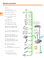
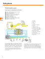
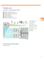
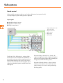
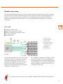
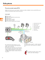
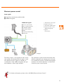
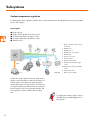
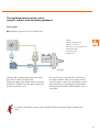
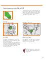
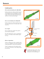
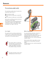
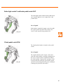
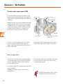
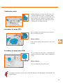
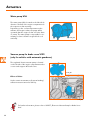
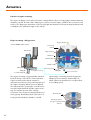
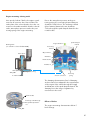
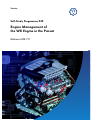
Service.
Self-Study Programme 249
Engine Management of
the W8 Engine in the Passat
Motronic ME 7.1.1
The Motronic engine management system of the
W8 engine enables high power output with minimal fuel consumption through adaptation to all
operating modes. The heart of the Motronic
system is the electronic control unit (J220). It processes incoming signals and transmits adjustment
commands for controlling the subsystems. At the
same time, the control unit serves the diagnosis
of subsystems and components.
S249_001
For further information on the W8 engine, please refer to SSP 248 „The W Engine Concept“.
NEW
This self-study programme explains the design
and function of new developments.
The contents are not updated.
2
Please always refer to the relevant Service literature for current
inspection, adjustment and repair instructions.
Important
Note
Table of Contents
Introduction . . . . . . . . . . . . . . . . . . . . . . . . . . . . . . . . . . 4
System overview . . . . . . . . . . . . . . . . . . . . . . . . . . . . . 6
Subsystems . . . . . . . . . . . . . . . . . . . . . . . . . . . . . . . . . . 8
Sensors . . . . . . . . . . . . . . . . . . . . . . . . . . . . . . . . . . . . 20
Actuators . . . . . . . . . . . . . . . . . . . . . . . . . . . . . . . . . . . 28
Functional diagram . . . . . . . . . . . . . . . . . . . . . . . . . . 38
Service . . . . . . . . . . . . . . . . . . . . . . . . . . . . . . . . . . . . . 42
Test your knowledge . . . . . . . . . . . . . . . . . . . . . . . . . . 46
3
Introduction
The Motronic ME 7.1.1
The regulation of the W8 engine is performed by
the Motronic ME 7.1.1. The management system of
the W8 engine is, in many respects, the same as
that of the VR6-V4 engine. These are the tasks of
the engine management system:
- Optimisation of the fuel-air mixture for all
operating modes
- Reduction of fuel consumption
- Regulation of combustion
- Monitoring and regulation of exhaust
emissions.
S249_002
The control unit is located in the electrics box in
the plenum chamber.
S249_003
The control unit performs the following functions:
-
4
Regulation of injection
Regulation of ignition (ignition system with single-spark ignition coils)
Regulation of idling speed
Stereo lambda regulation of exhaust emissions
Fuel tank ventilation system
Electronic power control
Cruise control system
Secondary air system
Knock control
Continuously variable inlet valve timing, two-position exhaust valve timing
Control of engine mountings
Regulation of coolant temperature
Regulation of electric vacuum pump
ESP
Self-diagnosis
The engine control unit in the CAN data bus
The engine control unit communicates with the control units in other vehicle systems.
Data is exchanged through the CAN data bus, which joins the individual control units in a single system.
Drivetrain CAN
ABS
Steering angle
control unit
sensor
Dash panel insert
CAN High
Engine control
unit
CAN Low
Gearbox
Airbag
Air conditioning
control unit
control unit
control unit
Immobiliser
S249_004
Through the CAN data bus, data are exchanged between the engine control unit and
-
the ABS control unit
the gearbox control unit
the airbag control unit
the steering angle sensor
the air conditioning control unit
the dash panel insert (control unit with display unit in dash panel insert)
the immobiliser.
For further information, please refer to SSP 186 „The CAN Data Bus“.
5
System overview
Sensors
G70 Air mass meter
G42 Intake air temperature sender
G28 Engine speed sender
G62 Coolant temperature sender
G83 Coolant temperature sender
radiator outlet
G39 Lambda probe
G108 Lambda probe II
Dash panel insert J285
G130 Lambda probe after catalyst
G131 Lambda probe II after catalyst
(control unit with display unit
in dash panel insert)
G40 Hall sender 1, G163 Hall sender 2
G300 Hall sender 3, G301 Hall sender 4
Radiator fan 2
G61 Knock sensor 1, G66 Knock sensor 2
G198 Knock sensor 3, G199 Knock sensor 4
control unit J293
J338 Throttle valve control part
G187 Throttle valve drive angle sender 1
G188 Throttle valve drive angle sender 2
Accelerator pedal module with
G79 Accelerator pedal position sender 1
G185 Accelerator pedal position sender 2
E45 Cruise control switch
E227 Cruise control „Set“ button
F
F47
Engine control unit J220
Brake light switch
Cruise control system brake pedal switch
CAN
F36
Clutch pedal switch
G294 Brake servo pressure sensor
(only with automatic gearboxes)
6
Diagnosis connection
Actuators
J17
Fuel pump relay, G6 Fuel pump
J 338 Throttle valve control part
G186 Throttle valve drive
N30 Injector, cylinder 1, N31 Injector, cylinder 2
N32 Injector, cylinder 3, N33 Injector, cylinder 4
N83 Injector, cylinder 5, N84 Injector, cylinder 6
N85 Injector, cylinder 7, N86 Injector, cylinder 8
N70 Ignition coil 1, N127 Ignition coil 2
N291 Ignition coil 3, N292 Ignition coil 4
N323 Ignition coil 5, N324 Ignition coil 6
N325 Ignition coil 7, N326 Ignition coil 8
N205Inlet camshaft timing adjustment valve 1, N208 valve 2
N318 Exhaust camshaft timing adjustment valve 1, N319 valve 2
N80 Activated charcoal filter system solenoid valve 1
N112 Secondary air inlet valve
V101 Secondary air pump motor,
J299 Secondary air pump relay
J271 Motronic current supply relay
J496 Additional coolant pump relay, V36 Water pump
F265 Map-controlled engine cooling thermostat
N144 Electro-hydraulic engine mounting solenoid valve
V7
S249_005
Radiator fan, V177 Radiator fan 2
J569 Brake servo relay,
V192 Vacuum pump for brake servo
(only for automatic gearboxes)
7
Subsystems
The fuel injection system
Input signals for calculating injection periods
●
●
●
●
●
●
●
●
Engine load signal from air mass meter
Intake air temperature
Signal from throttle valve control part
Signal from engine speed sender
Coolant temperature
Signal from Lambda probes
Signal from accelerator pedal module
Signal from Hall senders
1
Fuel tank
2 Fuel pump
3
2
1
5
6
Filter
4
Fuel rail
5
Fuel pressure regulator
6
Injectors
7
Engine control unit
8
Accelerator pedal module
9
Air mass meter with sender
for intake air temperature
6
6
3
10 Engine speed sender
6
11 Temperature sender (G62)
6
6
6
12 Lambda probes
6
13 Throttle valve control part
14 Hall senders
4
8
9
10
11
12
13
14
7
S249_006
The fuel pump, which is located in the fuel tank,
pumps fuel through the fuel filter to the injectors.
The injectors are connected to each other by the
fuel rail. Injection occurs sequentially. Using the
input signals, the control unit calculates the
necessary fuel quantity and the required injection period.
8
The quantity of fuel injected is determined solely
by the length of the period during which the
injector is open. The pressure regulator regulates
the injection pressure in the fuel rail and regulates the return flow of excess fuel to the fuel tank.
The ignition system
Input signals for calculating the ignition timing
●
●
●
●
●
●
●
Signal from engine speed sender
Engine load signal from air mass meter
Signal from throttle valve control part
Coolant temperature
Signal from knock sensors
Signal from Hall senders
Signal from accelerator pedal module
1 Single-spark ignition coils
with output stage
2 Engine control unit
3
4
5
6
7
8
3 Air mass meter
4 Engine speed sender
5 Temperature sender (G62)
9
6 Throttle valve control part
2
7 Knock sensor
1
8 Accelerator pedal module
9 Hall senders
10
10 Spark plugs
9
10
1
9
S249_007
The ignition timing is calculated according to a
map stored in the engine control unit on the basis
of the input signals.
9
Subsystems
Knock control
Unfavourable operating conditions can lead to self-ignition (pre-ignition knock).
Consequently, the ignition timing must be adjusted.
Input signals
● Signal from knock sensors
● Signal from Hall senders
● Engine temperature
1 Single-spark ignition coils
with output stage
2 Engine control unit
3 Knock sensors
2
4 Hall senders
3
4
5 Spark plugs
1
5
3
4
5
1
4
3
3
S249_008
Each bank of the W8 engine is equipped with
two knock sensors mounted on the crankcase. To
prevent the connectors in the wiring harness from
being interchanged on the sensors, the connections are colour coded. The knock signals can be
related to individual cylinders with the aid of the
Hall signals.
10
When knocking is detected in a cylinder, the
engine management system changes the ignition
timing of the knocking cylinder (by retarding the
firing point) until the knocking ceases.
When the affected cylinder no longer has the
tendency to knock, the control unit returns the
ignition timing to its former setting (advancing
the firing point).
Variable valve timing
The task of variable valve timing is to set the best valve timing for the operating modes idle, maximum
power and torque. Variable valve timing optimises the ratio between fresh air and exhaust gas. This is
referred to as internal exhaust gas recirculation. The overlap angle, during which the inlet valve is
already opening while the exhaust valve is not yet closed, determines the quantity of „recirculated“
exhaust gas.
Input signals
●
●
●
●
●
Signal from Hall senders
Signal from engine speed sender
Engine load signal from air mass meter
Coolant temperature
Oil temperature
1 Solenoid valves
2 Engine control unit
6
7
3
4
3 Air mass meter
5
4 Engine speed sender
5 Temperature sender
1
at engine outlet
6 Hall senders
6
2
7 Oil temperature
1
S249_009
6
To adjust the camshafts, the engine control unit
requires information on engine speed, engine
load, engine temperature, positions of the
crankshaft and camshafts and, from the dash
panel insert via CAN, oil temperature. The
engine control unit actuates the solenoid valves
according to operating mode.
The camshafts are adjusted according to a map
stored in the engine control unit, whereby the
inlet camshafts can be continuously adjusted. The
camshaft adjusters on the exhaust camshafts are
always moved by the engine control unit to one
end position or the other.
For further information, please refer to SSP 246 „Variable Valve Timing with Fluted Variator“.
11
Subsystems
Stereo lambda regulation
The task of the lambda regulation is to maintain a lambda value of 1 during combustion so that exhaust
gases can be optimally cleaned in the catalyst.
Input signals
●
●
●
●
Signal from engine speed sender
Engine load signal from air mass meter
Signal from lambda probes
Coolant temperature
1 Injectors
6
2 Engine control unit
5
3 Air mass meter
4
3
7
4 Engine speed sender
1
5 Pre-catalyst
lambda probes
6 After-catalyst
lambda probes
7 Coolant temperature
2
1
6
5
S249_010
During stereo lambda regulation, separate regulation loops, each including a catalyst, a precatalyst probe and an after-catalyst probe,
determine the correct fuel-air mixture for each
cylinder bank.
The lambda probes inform the control unit of the
residual oxygen content in the exhaust gas.
Using this signal, the control unit calculates the
momentary composition of the fuel-air mixture.
When deviation from the specified value occurs,
the injection period is corrected.
In addition, adaptive lambda regulation takes
place. (The control unit adapts to the operating
conditions and stores the learnt values.)
For further information, please refer to
SSP 175 „On-Board Diagnosis System
II“.
12
The fuel tank ventilation system
Input signals for fuel tank ventilation regulation
●
●
●
●
●
Engine speed
Engine load signal from air mass meter
Engine speed
Signal from lambda probes
Signal from throttle valve control part
5
6
7
8
9
3
4
1
Fuel tank;
2
Activated charcoal filter
3
Solenoid valve for
activated charcoal filter
4
Engine control unit
5
Air mass meter
6
Engine speed sender
7
Temperature sender
at engine outlet
8
Lambda probes
9
Throttle valve control part
2
1
249_011
The fuel tank ventilation system prevents fuel
vapour which develops in the tank from escaping
to the atmosphere. The fuel vapour is stored in
the activated charcoal filter. After evaluating the
input signals, the engine control unit actuates the
solenoid valve.
The fuel vapour stored in the activated charcoal
filter is directed through the intake manifold to
the engine for combustion.
This briefly changes the fuel-to-air ratio. The
change in the mixture is registered by the
lambda probes, causing lambda regulation to be
activated by the engine control unit and the mixture settles back to lambda = 1.
For further information, please refer to
SSP 231 „Euro On-Board Diagnostic
System“.
13
Subsystems
The cruise control system (CCS)
With the aid of the cruise control system, a vehicle speed above 30 km/h can be specified. This speed
will then be maintained without driver intervention.
Input signals
●
●
●
●
●
●
Engine speed
Engine load signal from air mass meter
Vehicle speed
Signal „brake operated“
Signal „clutch operated“
„On“ and „off“ signals from CCS switch
8
3
4
5
Feedback:
2
Throttle valve
6
1
Throttle valve control part
2
Engine control unit
3
Air mass meter
4
Engine speed sender
5
Brake pedal switch
6
Clutch pedal switch
7
CCS switch
8
Vehicle speed
Operation of
positioning motor
position
1
7
S249_012
The signal from the CCS switch goes to the
engine control unit which in turn actuates the
throttle valve control part.
The throttle valve control part opens the throttle
valve according to the speed set. If the vehicle is
equipped with a multi-function steering wheel,
an additional CCS switch is located on the steering wheel.
14
The signal „brake operated“ or „clutch operated“
causes the cruise control system to be switched
off.
For further information, please refer to
SSP 195 „The 2.3 ltr. V5 Engine“.
Electronic power control
Input signals
● Signal from accelerator pedal module
● Additional signals
1 Throttle valve control part
Additional signals
2 Engine control unit
● Cruise control system
3 Accelerator pedal module
● Air conditioning system
4 Electronic power control
● Lambda regulation
(EPC) warning lamp
● Automatic gearbox
5 Ignition,
● ABS
Fuel injection
● Power-assisted steering
● Alternator
3
2
1
5
4
S249_013
The driver’s input, i.e. the signals from the accelerator pedal, are transmitted to the engine control
unit, which uses these signals to calculate, in
consideration of the additional signals, the optimal realisation of the torque demand.
This realisation is achieved via the throttle valve
(which is adjusted by an electric motor), the ignition and the fuel injection. The ESP warning lamp
indicates to the driver that there is a fault in the
electronic power control system.
For further information, please refer to SSP 210 „Electronic Power Control“.
15
Subsystems
The secondary air system
Input signals
●
●
●
●
Signal from lambda probes
Coolant temperature
Engine load signal from air mass meter
Engine speed
7
8
11
3
2
1
6
4
1
Secondary air pump relay
2
Secondary air pump
3
Secondary air inlet valve
4
Combination valve
5
Catalyst
6
Engine control unit
7
Air mass meter
8
Temperature sender
2
at engine outlet
4
9
Pre-catalyst lambda probes
10 After-catalyst lambda probes
11 Engine speed sender
10
5
9
9
5
10
S249_014
The secondary air system reduces the exhaust
emissions following a cold start. During the
warm-up phase, the level of unburned hydrocarbons is elevated. The catalyst cannot process this
amount because it has not yet attained its operating temperature, but a mixture of lambda = 1
must be attained. Blowing in air behind the
exhaust valve enriches the exhaust gas with oxygen, and post-combustion occurs. The heat
released warms the catalyst more quickly to its
operating temperature.
16
The input signals enter the engine control unit,
which then actuates the secondary air pump and
the secondary air inlet valve simultaneously via
the secondary air pump relay. Vacuum from the
secodary air inlet valve operates the combination valve. The secondary air pump briefly forces
air into the exhaust gas stream behind the
exhaust valve. Beginning at partial load, the
secondary air system is switched off.
Engine mounting regulation
Input signals
● Signal from engine speed sender
● Vehicle speed
1 Electro-hydraulic engine
3
mounting solenoid valve
5
2 Engine mounting
4
3 Engine control unit
4 Engine speed sender
5 Vehicle speed
To intake manifold
1
2
2
S249_015
The hydraulically damped engine mountings with
electro-pneumatic actuation reduce the transmission of engine oscillation to the body over the
entire engine speed range.
Depending on the engine speed and the vehicle
speed, the engine control unit actuates the solenoid valve. The solenoid valve switches between
the damped engine mounting state in idling
mode and the undamped engine mounting state
in driving mode.
17
Subsystems
Coolant temperature regulation
Coolant temperature regulation enables the coolant temperature to be adapted to the current operating
mode of the engine.
Input signals
●
●
●
●
●
Engine speed
Engine load signal from air mass meter
Coolant temperature at engine outlet
Coolant temperature at radiator outlet
Vehicle speed
1
Map-controlled engine cooling
thermostat
2 Radiator fan
7
6
1
9
8
2
10
4
5
3
Radiator fan 2
4
Radiator fan 2 control unit
5
Water pump
6
Engine control unit
7
Air mass meter
8
Engine speed sender
9
CAN
Temperature sender at engine
outlet
10 Temperature sender at radiator
3
outlet
11 Speed signal from
11
S249_016
ABS control unit J104
If, after the input signals have been evaluated, a
larger cooling capacity is required, the map-controlled engine cooling thermostat is actuated,
opening the larger coolant circuit. To increase the
cooling capacity, both radiator fans are actuated
by the engine control unit, whereby radiator fan
2 is switched on by the radiator fan 2 control
unit.
For further information, please refer to
SSP 222 „Electronically Mapped Cooling System“.
18
The regulated vacuum pump system
(only for vehicles with automatic gearboxes)
Input signals
● Signal from pressure sensor for brake servo
1 Relay
2 Electric vacuum pump
3 Engine control unit
4 Pressure sensor for brake servo
5 Anti-return valve
3
6 To intake valve
4
7 Brake servo
1
7
5
5
2
S249_017
6
Vehicles with an automatic gearbox are equipped with an electric vacuum pump.
This pump supports the brake servo by ensuring
that there is sufficient vacuum at the connection
point for the brake servo.
The pressure sensor measures the current pressure and sends this value to the engine control
unit. The engine control unit compares the actual
value with the stored specification and actuates
vacuum pump for brakes V192 via brake servo
relay J569.
For further information, please refer to SSP 257 „Electronic Vacuum Pump for Brake Servo
Unit“.
19
Sensors
Air mass meter G70 with intake air temperature sender G42
Air mass meter G70 with backflow recognition
and intake air temperature sender G42 are integrated in one component which is located in the
intake tract at the air filter housing. The air mass
meter determines the mass of the inducted air
and sender G42, the temperature.
S249_018
Use of the signal
Effects of failure
The air mass meter signal is used for calculating
all functions dependent on engine speed and
load like, for example, injection period, ignition
timing, variable valve timing and fuel tank ventilation.
If the signal fails, the engine control unit calculates a substitute value.
For further information, please refer to
SSP 195 and SSP 252.
Engine speed sender G28
The engine speed sender G28 is located in the
gearbox housing. It senses the teeth of the dualmass flywheel. On the basis of these signals, the
engine control unit determines the engine speed
and the crankshaft position.
The gap in the sender wheel serves as a reference point for the engine control unit.
S249_019
Use of the signal
Effects of failure
This signal is used to calculate the injection time,
the injection quantity and the ignition timing. Further, it is used for variable valve timing and tank
ventilation.
If the signal fails, the engine cannot run.
For further information, please refer to
SSP 127 „VR 6 Engine“.
20
Coolant temperature senders G62 and G83
The actual values of the coolant temperature are
measured at two different points. Coolant temperature sender G62 is located on the engine block
(at the coolant outlet) and coolant temperature
sender G83 on the radiator outlet.
S249_020
Sender G62
Coolant outlet at rear of engine
Sender G83 at radiator outlet
S249_022
S249_021
Use of signal
Effects of signal failure
The signals of both temperature senders G62
and G83 serve the coolant temperature regulation in the coolant circuit.
The signal from temperature sender G62 is used
as an input signal for calculating injection periods and ignition timing, for idling speed regulation, for fuel tank ventilation and for the
secondary air system.
If the signal fails, the control unit uses a substitute
temperature stored in it. The fans go into emergency operation (both fans run).
For further information, please refer to
SSP 222 „Electronically Mapped Cooling System“.
21
Sensors
Lambda probes
The broad-band lambda probes G39, G108
Broad-band lambda probe
Each is located in the exhaust manifold of its specific bank upstream to the catalyst (pre-catalyst
probe). With the wide-band lambda probe, the
oxygen content in the exhaust gas can be determined over a wide measuring range.
S249_023
The two-state lambda probes G130, G131
Each is located in the exhaust manifold of its specific bank downstream to the catalyst (after-catalyst probe).
G108
Use of signal
Exhaust manifold
bank II
The pre-catalyst probe supplies the signal for
fuel-air mixture preparation.
G131
Catalyst
The after-catalyst probe serves for checking the
function of the catalyst and the lambda regulation loop.
S249_024
Two-state lambda probe
Effects of signal failure
If the pre-catalyst probe fails, no lambda regulation can occur. Adaptation is blocked. Emergency
running dependent on map control takes place.
S249_025
If the post-catalyst probe fails, lambda regulation continues. The function of the catalyst cannot
be monitored.
For further information, please refer to
SSP 175 „On-Board Diagnose II“ and
SSP 231 „Euro-On-Board-Diagnose“.
22
Brake servo pressure sensor G294
(only for vehicles with automatic gearbox)
The brake servo pressure sensor is located in the
plenum chamber below the vacuum line to the
brake servo. It transmits a voltage signal to the
engine control unit.
S249_027
Effects of signal failure
If the signal fails, the engine control unit calculates the pressure in the brake servo on the basis of
the input values for engine load, engine speed,
throttle valve position and brake light switch, and
actuates the vacuum pump.
S249_026
For further information, please refer to SSP 257 „Electronic Vacuum Pump for Brake Servo
Unit“.
23
Sensors
Hall senders G40, G163, G300, G301
All Hall senders are located in the timing chain
cover of the engine. They have the task of informing the engine control unit of the positions of
the inlet and exhaust camshafts by sensing a
quick-start sender wheel located on the respective camshaft.
S249_028
Quick-start
Hall sender
sender wheel
S249_029
Exhaust II
Inlet II
Inlet I
Exhaust I
G301
G163
G40
G300
Use of signal
Effects of signal failure
Hall senders G40 and G163 indicate to the
engine control unit the positions of the inlet
camshafts and Hall senders G300 and G301, the
positions of the exhaust camshafts.
The signals of all four Hall senders serve as input
signals for variable valve timing as well as for
the calculation of sequential injection and ignition timing.
The signal from sender G40 is also used for
determining the TDC point of the No. 1 cylinder.
If a Hall sender fails, the camshafts cannot be
adjusted. However, the engine continues to run,
and will also start again after it is shut off.
For further information, please refer to
SSP 127 „VR 6 Engine“.
24
Knock sensors G61, G66, G198, G199
The electronic regulation of ignition timing is
based on cylinder-specific knock control. The W8
engine has two knock sensors on each bank,
located on the crankcase.
G198
G199
S249_033
S249_030
G61
G66
S249_032
S249_031
Use of signal
Effects of signal failure
The knock sensors indicate to the engine control
unit when knocking combustion occurs. It initiates
an ignition timing adjustment until the knocking
ceases.
If a knock sensor fails, the ignition timing of the
affected cylinders is retarded. If all knock sensors
fail, the engine management system switches to
emergency knock control, during which the ignition timing is generally retarded so that the maximum engine output is not available.
For further information, please refer to
SSP 127 „VR 6 Engine“.
25
Sensors
The accelerator pedal module
The accelerator pedal module is located on the
pedal cluster and consists of
● the accelerator pedal
● the accelerator pedal position sender G79
and
● the accelerator pedal position sender 2 G185.
Both senders are sliding contact potentiometers
located on a common shaft.
Every change in the accelerator pedal position
changes the resistance of the sliding contact
potentiometers and consequently the voltage
transmitted to the engine control unit.
S249_034
S249_035
Senders
Use of signal
Effects of signal failure
The signals from the accelerator pedal position
senders serve to communicate the driver’s input
to the engine control unit and also as kickdown
information for the automatic gearbox.
If a sender fails, the pedal value is limited to a
defined value. At full load, the output is
increased slowly. If the signals between G79 and
G185 implausible, the lower value is used.
The EPC (electronic power control) warning lamp
indicates a fault.
No separate switch is used for kickdown information. A mechanical pressure point is integrated in the gas
pedal module which communicates
the „kickdown feeling“ to the driver.
For further information, please refer to
SSP 210 „Electronic Power Control“.
26
If both senders fail, the engine will run only at
idle and does not respond to the accelerator
pedal.
The EPC (electronic power control) warning lamp
indicates a fault.
Brake light switch F and brake pedal switch F47
The brake light switch and the brake pedal switch
are located together in one component on the
pedal cluster.
Use of signal:
S249_037
Both switches supply the engine control unit with
the signal „brake operated“. This leads to the
cruise control system being switched off.
Clutch pedal switch F36
The clutch pedal switch is located on the pedal
cluster.
Use of signal
S249_036
The signal indicates to the engine control unit
when the clutch pedal is operated, at which point
the cruise control system is switched off. When
the clutch pedal is operated, the quantity of fuel
injected is briefly reduced to prevent the engine
speed from increasing while the gear is changed,
reducing the jolt when load returns.
27
Sensors / Actuators
Throttle valve control part J338
The throttle valve control part is located on the
intake manifold and has the task of providing the
engine with the required quantity of air under all
conditions.
Throttle body
Intake connection
Throttle valve drive
It differs from the control part installed in the VR6
engine in that the intake connection has a greater diameter. This is necessary because the W8
engine has a greater need for air due to its greater displacement. Further, the connection for
throttle valve heating has been eliminated.
S249_038
Throttle valve
Throttle valve drive angle
senders 1+2
To open or close the throttle valve as well as to
adjust a particular throttle valve setting, the
engine control unit actuates the electric motor for
throttle valve drive.
Both angle senders transmit the current position
of the throttle valve to the engine control unit.
Effects of signal failure
If the throttle valve drive fails, the throttle valve is
automatically drawn to the emergency running
position, permitting limited operation with an
increased idling speed.
If both angle senders fail, the throttle valve drive
is switched off. The engine will only run at an
increased idling speed.
If an angle sender fails, the maximum output will
not be available.
However, the engine can be started and the
vehicle driven.
For further information, please refer to
SSP 210 „Electronic Power Control“.
28
Fuel pump G6
The fuel pump is installed directly in the fuel tank.
With the aid of the pressure regulator, it creates
a pressure of 4 bar in the fuel system.
To supply the engine, fuel is delivered from the
fuel pump G6 through the fuel filter to the fuel
rail.
G6
S249_039
S249_040
Effects of failure
If the fuel pump fails, no fuel is delivered.
The engine stops.
In addition, fuel pump G23 is located in the additional fuel tank and a suction-jet pump in the
fuel tank. The fuel pump G23 is actuated by fuel pump control unit J538 and delivers fuel from
the additional fuel tank to the main fuel tank. The suction-jet pump ensures that fuel from the
left chamber of the fuel tank reaches the fuel pump G6. Neither fuel pump G23 nor the suction-jet pump are actuated by the engine control unit.
For further information, please refer to SSP 261 „The Passat W8“.
Fuel pump relay J 17
The fuel pump relay actuates the fuel pump
when it receives an impulse from the engine control unit.
S249_041
For further information, please refer to
SSP 127 „VR 6 Engine“.
Effects of failure
If the relay fails, the engine cannot be started.
29
Actuators
Injectors N30, N31, N32, N33, N83, N84, N85, N86
The injectors are actuated by the engine control
unit according to the firing order.
They are secured with retaining clips directly to a
common fuel rail and inject atomised fuel immediately before the inlet valve.
S249_042
Effects of failure
S249_043
If individual injectors fail, fuel is not injected at
that position. This means that the engine runs at
reduced output.
For further information, please refer to
SSP 127 „VR 6 Engine“.
Single-spark ignition coils
N70, N127, N291, N292, N323, N324, N325, N326
The single-spark ignition coils deliver only one
spark via the spark plugs, and one is fitted at
each cylinder.
S249_045
An output stage and an ignition coil are combined in each element so that the engine management system can influence the ignition
individually for each cylinder.
Effects of failure
If an ignition coil fails, injection is switched off for
that cylinder.
This prevents damage to the catalyst.
S249_044
30
Inlet camshaft timing adjustment valves 1 N205 and 2 N208 and
Exhaust camshaft timing adjustment valves 1 N318 and 2 N319
In the process, valves N205 and N208 are
responsible for the continuous adjustment of the
inlet camshafts and valves N318 and N319, for
the adjustment of the exhaust camshafts. The
exhaust camshaft adjusters can only be set to the
end positions „advanced“ or „retarded“.
The solenoid valves are integrated in the control
housing of the camshaft adjuster. They direct the
oil pressure to the camshaft adjusters according
to the specifications of the engine control unit in
regard to the direction and distance of adjustment. Fluted variators are used as camshaft
adjusters.
Inlet camshaft
Fluted variator
N205
N318
S249_047
Exhaust camshaft
Fluted variator
S249_046
Control housing
Effects of signal failure
If an electrical wire to the camshaft adjusters is
defective or if a camshaft adjuster fails, no camshaft adjustment can take place. In the event of an
electrical fault, the camshafts remain in their
reference positions (emergency running positions).
The reference point for all four camshafts is „retarded“.
For further information, please refer to
SSP 246 „Variable Valve Timing with
Fluted Variator“.
31
Actuators
Activated charcoal filter system solenoid valve 1 N80
Opening the solenoid valve empties the activated charcoal filter and directs the collected fuel
vapour to combustion.
Effects of signal failure
If current is interrupted, the valve remains shut
and tank ventilation cannot occur.
S249_049
To intake manifold
For further information, please refer to
SSP 174 „Changes in the VR6 Engine“.
From activated
S249_048
charcoal filter
Secondary air inlet valve N112
This solenoid valve is switched by the engine control unit and controls the combination valve via a
vacuum line.
S249_051
Effects of failure
If the control unit signal fails, the combination
valve cannot be opened.
The secondary air pump cannot inject air.
For further information, please refer to
SSP 174 „Changes in the VR6 Engine“.
32
S249_050
Combination valve
S249_055
Vacuum from the secondary air inlet valve operates the combination valve, opening the path
for air from the secondary air pump to the secondary air duct in the cylinder head. At the same
time, the valve prevents hot exhaust gases from
reaching the secondary air pump.
S249_053
Secondary air pump V101
The secondary air pump transports fresh air for
the secondary air system.
S249_052
Effects of failure
If the current supply is interrupted, no air is transported.
S249_054
Secondary air pump relay J299
The secondary air pump relay is actuated by the
engine control unit to switch on the secondary air
pump.
S249_041
Effects of failure
The secondary air pump will not run.
S249_056
For further information, please refer to SSP 174 „Changes in the VR6 Engine“ and SSP 217 „The
V8 V5 Engine“.
33
Actuators
Water pump V36
The water pump V36 is located on the left side (in
direction of travel) of the engine compartment on
the suspension strut mounting.
Depending on the coolant temperature at the
radiator and engine outlets, the pump will be
operated after the engine is shut off on the basis
of a map. The water pump is responsible for circulating coolant so that the engine block cools
uniformly.
S249_057
Vacuum pump for brake servo V192
(only for vehicles with automatic gearboxes)
The regulated electric vacuum pump is located
on the left side of the engine compartment under
a cover and supports the brake servo.
S249_061
Effects of failure
Under certain circumstances (frequent braking)
sufficient vacuum cannot be built up.
S249_060
For further information, please refer to SSP 257 „Electronic Vacuum Pump for Brake Servo
Unit“.
34
Map-controlled engine cooling thermostat F265
S249_058
Resistance
The thermostat is inserted in the upper part of the
crankcase from above. The thermostat switches
between the small and the large cooling circuits.
The individual engine operating phases require
different engine temperatures. The thermostat is
actuated by the engine control unit according to
the needs. A map is stored in the engine control
unit to attain the desired temperature.
heater
Wax element
S249_059
Lifting pin
Effects of failure
At a temperature of 110° C or above, the large
cooling circuit is opened and the radiator fans
are actuated.
For further information, please refer to
SSP 222 „Electronically Mapped Cooling System“.
Engine mountings
Two hydraulically damped engine mountings ensure improved driving comfort. They reduce the transmission of engine vibration to the body.
Right engine mounting Right engine support
Left engine support
Right engine
console
Left engine mounting
Cap
Mounting cover
S249_062
Front cross member
Left engine console
Vacuum connection
S249_095
35
Actuators
Function of engine mountings
The engine oscillation on a bad road surface is damped by the flow of a liquid (glycol mixture) between
chambers 1 and 2. The task of the damping is to reduce resonant engine oscillation due to uneven road
surface. The damping is dependent on the form (length and diameter) of the spiral-shaped channel and
is adapted to the particular engine in the vehicle.
Engine mounting - idling position
Engine vibration
Solenoid N144 under current
Connecting
channel
Atmosphere
Glycol mixture
Chamber 1
Nozzle bodies
Chamber 2
Valve plate
S249_101
Positioning spring
To engine mounting
S249_096
Vacuum connection
To intake manifold
The engine mounting is pneumatically actuated
by the 3/2-way solenoid. The electro-hydraulic
engine mounting valve directs vacuum or
atmospheric pressure to the positioning spring of
the engine mounting. When current is applied,
the valve plate lifts, opening the connection between the intake manifold and the engine mounting. The vacuum present at the vacuum
connection of the engine mounting pulls the positioning spring downwards, which opens the connecting channel between chambers 1 and 2.
Opening the connecting channel changes the
damping. The mounting is dynamically soft,
which reduces the transmission of engine vibration at idling speed.
Nozzle bodies
Exchange of fluid
through connecting
channel
S249_102
36
Engine mounting - driving mode
At a speed of about 5 km/h, the engine control
unit cuts off current to the solenoid valve. The
valve plate of the solenoid valve closes the connection to the intake manifold. Via the solenoid
valve, atmospheric pressure reaches the positioning spring of the engine mounting.
Due to the atmospheric pressure at the positioning spring, the connecting channel between
chambers 1 and 2 closes. The exchange of fluid
(glycol mixture) between the two chambers
occurs through the spiral-shaped channel in the
nozzle bodies.
Engine vibrations
Resting state
(no current to solenoid valve N144)
Spiral-shaped
channel
Connecting
channel
Glycol mixture
Atmosphere
Chamber 1
Nozzle bodies
Chamber 2
S249_097
Valve plate
To engine mounting
S249_100
Positioning
Vacuum connection
To intake manifold
spring
The damping characteristics (level of damping
and resonance) are adapted to the requirements
of the engine in the vehicle through the length
and diameter of the spiral-shaped channel. The
damping lies in the range of agitation by
unevenness in the road.
Nozzle bodies
Exchange of fluid through
Effects of failure
the spiral-shaped channel.
S249_086
The engine mountings characteristics below 5
km/h change.
37
Functional diagram
Functional diagram
Kl. 30
Kl. 15
J271
a
S
S
S
S
E227
E45
N30 N31 N32 N33 N83 N84 N85
N86
J220
N 70
N127
N291
N323
N292
N324
N325
N326
S249_070
- CCS switch
N70 - Ignition coil 1
E227 - CCS button
N127 - Ignition coil 2
J220 - Motronic control unit
N291 - Ignition coil 3
J271
N292 - Ignition coil 4
E45
38
- Motronic current supply relay
N30 - Injector, cylinder 1
N323 - Ignition coil 5
N31
- Injector, cylinder 2
N324 - Ignition coil 6
N32 - Injector, cylinder 3
N325 - Ignition coil 7
N33
- Injector, cylinder 4
N326 - Ignition coil 8
N83
- Injector, cylinder 5
P
- Spark plug connector
N84 - Injector, cylinder 6
Q
- Spark plug
N85
- Injector, cylinder 7
S
- Fuse
N86
- Injector, cylinder 8
Kl. 30
Brake
lights
Kl. 15
b
a
a
S
F36
F47
S
S
F
N80
N112
G294
G70
J220
G61
G66
G199
G198
G83
S249_071
- Brake light switch
J220 - Motronic control unit
F36
- Clutch pedal switch
N80 - Activated charcoal filter system solenoid valve 1
F47
- CCS brake pedal switch
N112 - Secondary air inlet valve
G61
- Knock sensor 1
S
G66
- Knock sensor 2
F
- Fuse
G198 - Knock sensor 3
G199 - Knock sensor 4
G70 - Air mass meter
G83
- Coolant temperature sender
G294 - Brake servo pressure sensor
(only for automatic gearboxes)
Colour coding/Key
= Input signal
= Output signal
= Positive
= Earth
= CAN data bus
39
Functional diagram
Kl. 30
Kl. 15
b
b
a
a
S
G79
G185
G130
G39
G131
G108
J220
J293
J338
G187
G188
G186
S249_072
- CAN Low
J
B
- CAN High
J220 - Motronic control unit
G39
- Lambda probe
J293
- Radiator fan control unit
G108 - Lambda probe II
J338
- Throttle valve control part
G130 - Lambda probe after catalyst
S
- Fuse
A
G131
- Diagnosis wire
- Lambda probe II after catalyst
G79
- Accelerator pedal position sender
G185
- Accelerator pedal position sender 2
Colour coding/Key
G186 - Throttle valve drive
= Input signal
G187
= Output signal
- Throttle valve drive angle sender 1
G188 - Throttle valve drive angle sender 2
= Positive
H, I
= Earth
- Radiator fan control
= CAN data bus
40
Kl. 30
Kl. 15
J17
b
a
S
S
J299
J569
S
S
J496
N144
V192
V101
N205
N318
N319
N208
F265
V36
J220
G6
G28
G40
G163
G301
G300
G62
S249_073
F265 - Map-controlled engine cooling thermostat
J496 - Additional coolant pump relay
G6
J569 - Brake servo relay
- Fuel pump
G28 - Engine speed sender
N144 - Electro-hydraulic engine mounting solenoid valve
G40 - Hall sender 1
N205 - Inlet camshaft timing adjustment valve 1
G163 - Hall sender 2
N208 - Inlet camshaft timing adjustment valve 2
G300 - Hall sender 3
N318 - Exhaust camshaft timing adjustment valve 1
G301 - Hall sender 4
N319 - Exhaust camshaft timing adjustment valve 2
G62 - Coolant temperature sender
S
- Fuse
J17
V36
- Water pump
- Fuel pump relay
J220 - Motronic control unit
V101 - Secondary air pump
J299 - Secondary air pump relay
V192 - Vacuum pump for brakes
41
Service
Self-diagnosis
The engine control unit enables a broad self-diagnosis of all subsystems and electrical components.
These vehicle diagnosis systems are used for communication:
● VAS 5051
● VAS 5052
With the vehicle diagnosis, testing and information system VAS 5051,
●
●
●
●
Vehicle self-diagnosis
Testing
Guided fault finding and
Administration
can be performed.
VAS 5051
VAS 5052
Vehicle Diagnosis and Service Information System
Version -GB- / V01.02 20/08/2001
Vehicle
self-diagnosis
Testing
Guided
fault finding
Administration
Help
S249_080
The use of the vehicle diagnosis system VAS 5051 is explained in
SSP 202 „Vehicle Diagnosis, Testing and Information System VAS 5051“.
42
S249_089
With the vehicle diagnosis and service information system VAS 5052,
● Vehicle self-diagnosis
● Service Information System and
● Administration
can be performed.
VAS 5052
S249_081
The use of the vehicle diagnosis system VAS 5052 is explained in
SSP 256 „VAS 5052“.
43
Service
Read fault memory
When faults occur in the system, they will be detected by self-diagnosis and stored in the fault memory.
With function 02, the fault memory can be read using the vehicle diagnosis systems.
The following components are monitored by self-diagnosis.
G70
J17, G6
G28
J338
G62
G83
N30, N31,
N32, N33
G39
N83, N84,
G108
N85, N86
G130
G131
J285
N70, N127,
N291, N292
G40, G163,
N323, N324,
G300, G301
N325, N326
G61, G66,
J293
N205, N208,
N318, N319
G198, G199
N80
J338
N112
J299, V101
G79,
G185
J271
J220
E45, E227
J496, V36
F265
F, F47
N144
CAN
F36
V7, V177
JG294
J569, V192
S249_105
Please note that Repair group 01 is integrated in „Guided fault finding“. In it, you will also find
the functions „Read measured value block“ and „Final control diagnosis“.
44
Erase fault memory
This function erases the contents of the fault memory following „Read fault memory“. However, the readiness code and various adaptation values such as the camshaft and lambda adaptation values will also
be erased. To ensure that the fault memory is properly erased, the ignition must be switched off once.
Following „Erase fault memory“, one must check whether the camshafts have readapted themselves. Without adaptation, camshaft adjustment will not occur, resulting in a noticeable loss
in power. There are two ways to adapt the camshafts:
● Idle the engine briefly after erasing the fault memory and restarting the engine.
● Initiate basic settings following the instructions in the workshop manual.
Erasing the fault memory should be carefully considered because the readiness code will be
erased simultaneously, and „Create readiness code“ will be required.
The readiness code must always be created following a repair so that it will not be erased in
the course of further work. The readiness code can be created with the VAS 5051 using the
function „Guided fault finding“.
Readiness code
After the entire number of diagnoses has been performed, an 8-digit readiness code is set. Each position
of the number code may have the value 0 (diagnosis performed) or 1 (diagnosis not performed). The readiness code does not provide any information about whether a fault exists in the system. A lit-up exhaust
warning lamp is the visual indication of one or more detected and stored faults.
A vehicle must only leave the workshop and be delivered to the customer after the readiness
code has been generated.
For more information about the readiness code, please refer to SSP 175 as well as SSP 231.
45
Test Your Knowledge
1. The engine control unit receives the signal for engine load from
a. the lambda probes.
b. the air mass meter.
c. the accelerator pedal module.
2. Which tasks does the secondary air system perform?
a. It elevates exhaust emissions during the cold start phase.
b. It ensures that the engine operates with excess air.
c. The secondary air system increases performance in the partial-load range.
d. Secondary air injection brings the catalyst up to operating temperature more quickly.
3. What is the task of the brake servo pressure sensor G294?
a. The signal identifies faults in the brake system.
b. In brake systems with ESP, the pressure sensor is screwed directly into the hydraulic unit and
measures the current pressure in the brake system.
c. The pressure sensor measures the momentary pressure at the connection for the brake servo.
4. The coolant temperature is regulated using a map stored in the engine control unit.
The coolant temperature in any engine operating mode
a. is measured by a temperature sender and transmitted to the engine control unit.
b. is measured by two temperature senders and transmitted to the engine control unit.
46
5. If a temperature sender fails
a. the radiator fans go to emergency running mode.
b. the engine stops.
c. the control unit uses a substitute temperature stored in the engine control unit.
6. The electro-hydraulic engine mountings can change in their mounting characteristic.
A pneumatic 3/2-way solenoid valve is actuated by the engine control unit. Which
statements are true?
a. Current is supplied to the solenoid valve at 5 km/h.
b. Current is cut off to the solenoid valve at 5 km/h.
c. Current is supplied to the solenoid valve at idling speed.
d. The characteristic of the engine mounting when the solenoid does not receive current
is dynamically „soft“.
7. The readiness code
a. can be created with the VAS 5051 using the function „Guided fault finding“.
b. is an 8-digit code. From this code, one can determine whether the diagnoses were performed
or not.
c. provides information about faults which exist in the system.
47
Notes
48
49
Notes
50
51
Answers
1.) b
2.) d
3.) c
4.) b
5.) a, c
6.) b, c
7.) a, b
249
For internal use only © VOLKSWAGEN AG, Wolfsburg
All rights reserved. Technical specifications subject to change without notice
140.2810.68.20 Technical status 11/01
❀ This paper was produced from
non-chlorine-bleached pulp.