1
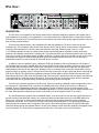
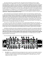
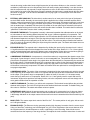
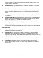
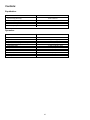
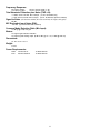
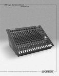
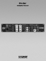
IPro One™
Intelligibility Processor
Intended to alert the user to the presence of uninsulated “dangerous voltage” within the product’s
enclosure that may be of sufficient magnitude to constitute a risk of electric shock to persons.
Intended to alert the user of the presence of important operating and maintenance (servicing)
instructions in the literature accompanying the product.
CAUTION: Risk of electrical shock — DO NOT OPEN!
CAUTION: To reduce the risk of electric shock, do not remove cover. No user serviceable parts inside. Refer
servicing to qualified service personnel.
WARNING: To prevent electrical shock or fire hazard, do not expose this appliance to rain or moisture. Before
using this appliance, read the operating guide for further warnings.
Este símbolo tiene el propósito, de alertar al usuario de la presencia de “(voltaje) peligroso” sin aislamiento dentro de la caja del producto y que puede tener una magnitud suficiente como para constituir
riesgo de descarga eléctrica.
Este símbolo tiene el propósito de alertar al usario de la presencia de instruccones importantes sobre la
operación y mantenimiento en la información que viene con el producto.
PRECAUCION: Riesgo de descarga eléctrica ¡NO ABRIR!
PRECAUCION: Para disminuír el riesgo de descarga eléctrica, no abra la cubierta. No hay piezas útiles dentro.
Deje todo mantenimiento en manos del personal técnico cualificado.
ADVERTENCIA: Para evitar descargas eléctricas o peligro de incendio, no deje expuesto a la lluvia o humedad
este aparato Antes de usar este aparato, Iea más advertencias en la guía de operación.
Ce symbole est utilisé dans ce manuel pour indiquer à l’utilisateur la présence d’une tension dangereuse
pouvant être d’amplitude suffisante pour constituer un risque de choc électrique.
Ce symbole est utilisé dans ce manuel pour indiquer à l’utilisateur qu’il ou qu’elle trouvera d’importantes
instructions concernant l’utilisation et l’entretien de l’appareil dans le paragraphe signalé.
ATTENTION: Risques de choc électrique — NE PAS OUVRIR!
ATTENTION: Afin de réduire le risque de choc électrique, ne pas enlever le couvercle. Il ne se trouve à l’intérieur
aucune pièce pouvant être reparée par l’utilisateur. Confiez I’entretien et la réparation de l’appareil à un réparateur
Crest agréé.
AVERTISSEMENT: Afin de prévenir les risques de décharge électrique ou de feu, n’exposez pas cet appareil à la
pluie ou à l’humidité. Avant d’utiliser cet appareil, lisez attentivement les avertissements supplémentaires de ce
manuel.
Dieses Symbol soll den Anwender vor unisolierten gefährlichen Spannungen innerhalb des Gehäuses
warnen, die von Ausreichender Stärke sind, um einen elektrischen Schlag verursachen zu können.
Dieses Symbol soll den Benutzer auf wichtige Instruktionen in der Bedienungsanleitung aufmerksam
machen, die Handhabung und Wartung des Produkts betreffen.
VORSICHT: Risiko — Elektrischer Schlag! Nicht öffnen!
VORSICHT: Um das Risiko eines elektrischen Schlages zu vermeiden, nicht die Abdeckung enfernen. Es befinden
sich keine Teile darin, die vom Anwender repariert werden könnten. Reparaturen nur von qualifiziertem
Fachpersonal durchführen lassen.
ACHTUNG: Um einen elektrischen Schlag oder Feuergefahr zu vermeiden, sollte dieses Gerät nicht dem Regen
oder Feuchtigkeit ausgesetzt werden. Vor Inbetriebnahme unbedingt die Bedienungsanleitung lesen.
2
IPro One™
DESCRIPTION:
The IPro One is a microphone or line input processor that is especially designed to optimize audio signals (low or
high impedance) for recording or live applications. It is an improvement over a standard mixer’s channel strip for direct
recording of a microphone or line instrument since it has functions not found in other analog signal processors. Here is a
brief summary of those features.
There are two balanced inputs, a low impedance XLR and high impedance 1/4" phono, which can be used
simultaneously. The microphone input has the same discrete circuitry that is used in console mixers, using transistors
claimed by their manufacturer to be the lowest noise devices in the world. Phantom power (+48 V), a +6 dB
to +56 dB gain adjustment control, a polarity reverse switch, and a 20 dB pad are available to match (and power)
whatever low impedance microphone is connected to it. Front and rear XLR input connectors allow the unit to be used
on the fly or as part of a permanent install. A tunable (10-350 Hz, 12 dB per octave) low cut filter is online to remove the
troublesome low frequency rumble and breath-blast noise that microphones often encounter. The mic pre-amp is
enabled with a switch so it can be turned off if the XLR input is not used.
In addition to the low impedance input, a balanced (TRS) high impedance (200 k ohms balanced, 100 k Ohms if
used unbalanced) line input is available which also has front and rear input jacks, permitting a guitar (or other line-level
source) to be connected easily even if the IPro One is mounted in a rack. Unlike the XLR input, the front panel jack
automatically disconnects the rear panel jack, allowing the unit to be switched from a rear jack configuration to a front
panel one simply by inserting a jack. This input has its own level control (off to 20 dB of gain) and can be mixed with the
XLR input if desired. The high and low impedance inputs are summed together and are routed to the rear insert jack
before proceeding to the input of the first parametric filter. The insert jack is enabled from the front panel. Even when not
in the signal path, the send (tip) signal is still present. This can be used as a dry pre-amp output, which is especially
useful when both the dry (pre-processing) and wet (post-processing) signals are required.
There are two parametric equalizers in the IPro One. Each has frequency, bandwidth, and level adjustments. Since
the usual use for a parametric EQ is to notch out an offending frequency, a deep 24 dB cut and a 12 dB boost is
available. There is considerable overlap in the two frequency ranges so that they can be set close together for the
occasional difficult feedback problems. With a bandwidth adjustment of 1/6 to 2 octaves, gentle or severe alterations can
be made. Each parametric equalizer has its own on/off switch to route the signal around it if it is unused.
The second parametric equalizer has an additional feature. It can be moved out from the main signal path into the
dynamic section’s side-chain path, where it is in series with (after) the side-chain insert jack of the RMS detector. By
setting it up in this mode, it can be used to define the frequencies that control the dynamics circuitry (expander,
compressor, and limiter). This is used for de-essing, for removing rumble modulation, or for specifying a problematic
frequency band to compress. When configured in this manner, any external signal brought in through the side-chain
insert jack passes through this equalizer before it is sent to the detector to allow frequency shaping to be applied to that
source as needed. The on/off switch still bypasses this filter even in this mode, just as you would expect.
3
A key part of the IPro One™ is its dynamics section. Using state-of-the-art integrated circuits for the voltage
controlled amplifier and true RMS detector, it has very low distortion and noise. Incorporated in the processing is a
downward expander, a compressor, and a limiter. Each has an independently adjustable threshold control. The expander
and compressor sections also have ratio controls. There is a side-chain insert in the detector path that can be enabled
from the front panel (see previous comment). The expander is of soft knee topology, and has a ratio control to allow it to
be used as a gentle-slope noise reduction circuit (low ratio), or a gate (high ratio). A threshold LED illuminates when the
expander is active. The compressor is also soft knee, but has a more gradual knee action for even smoother transitions.
It can be adjusted from no compression (1:1) to limit (infinite:1). The limiter is a compressor with a fixed infinite:1 ratio, a
faster knee transition, and an LED to show when it is functioning. All have preset (program dependant) attack and
release times. A twelve segment gain reduction meter displays all VCA activity (expander, compressor, and limit) so that
control action is easily seen, making adjustments a snap.
Heavy compression will give the perception of darkening the signal, since the low frequency components (which
have the most energy) dominate the compressor action. As the signal is compressed, the treble material is reduced at
the same ratio as the bass, causing it to lose definition. To compensate for this apparent loss and to add a new sheen to
signals which do not have much high frequency content, the SmarTube™ Enhance process was developed. This is a
high frequency harmonic generator based on our SmarTube tube simulation circuitry. It adds tunable upper frequency
harmonics, and will add pleasing high frequency detail not found in the source. A unique feature of the circuitry is that it
behaves as a tube does in its distortion characteristics and is level dependant. This means that more harmonics are
created at higher levels, which decrease as the source fades out, just as a natural sound would. This can bring a mic to
the front of a mix, or add atmosphere and clarity to an instrument.
There may be an occasion when certain frequencies must be compressed then added back to the original “dry”
signal, similar to using the IPro One as one of the bands of a multi-band compressor. A blend control was added so that
this could be done without having to sacrifice an external mixer channel (if one is available) to accomplish this feat.
Simply turn it to “wet” and set up the frequency band and dynamic action that you want processed, then blend this with
the “dry” signal to taste. By compressing the bass and adding it back to the original, a “fatter” sound can be created.
A headphone monitoring function with an independent level adjustment is included. This is especially needed when
the unit is used as a single channel recording preamp. Its signal is picked up before the main level control, and drives a
front panel headphone jack. The main level control sets the IPro One’s main balanced and unbalanced outputs. It will
adjust from “off” to +10 dB of gain. A twelve segment meter monitors either this output or the pre-amp signal, depending
on the meter switch setting. In the pre-amp position, it allows metering of the “dry” signal so that the mic or line gain can
be properly adjusted to the 0 dBu reference level. The main output has both a 1/4" unbalanced phone, and an XLR
balanced connector on the rear panel.
The unit is powered by an internal transformer, and has a standard IEC mains connector.
10
9
8
3
1
4
2
5
12
6
7
14 11
20
16 18
13
29
28
15
17 19
26
22
21
24 25 23
30
27
CONTROL FUNCTIONS:
1.
MIC INPUT: This is a balanced (XLR) input jack designed to receive a signal from a low impedance (150 Ohm)
microphone. This connector has +48 V phantom power when the phantom power switch is on. It can handle
signal levels as high as +30 dBu (at minimum gain, pad engaged). Pin 2 is the positive input, pin 3 is the
negative input, and pin 1 is ground.
4
2.
3.
+48 V: Turns on the +48 V phantom power for mics that require it. Do not enable phantom power if an
unbalanced low impedance mic is used, since the mic could be damaged. The LED will light if phantom
power is present.
POLARITY: The polarity of the mic input can be reversed in the event that the signal is out of phase with either
the line or other signals. This can happen when miking the top and bottom of the soundboard of a piano, or both
sides of a speaker cabinet or a drum head.
4.
PAD: If the input level is too hot, and the gain control cannot be turned down far enough to avoid distortion,
engage this switch. This attenuates the input signal by 20 dB. It reduces the level of the input stage to avoid preamp clipping, which could occur when close miking loud sources.
5.
MIC ON: Enables the XLR input. If the mic input is not used, it should be turned off. This will improve the signalto-noise ratio by removing all residual mic pre-amp noise from the signal path. This switch can also be thought
of as a mic mute, if the mic must be turned off temporarily when it is active. The LED will light when the mic
input is live.
6.
LOW CUT FREQUENCY: The low-cut filter (on the mic input only) is adjustable from 10 Hz to 350 Hz, and is
always on line. To minimize its effect, set it fully CCW (10 Hz). Adjust this control to reduce the boom and thump
of proximity breath effects, stage rumble, and handling noise. It has a 12 dB per octave slope. This control is
before the insert point, so its adjustment will affect the “dry” signal throughout the unit.
7.
GAIN: This control sets the gain of the mic pre-amp, and should be adjusted to provide a nominal signal level of
0 dBu at the “dry” output. This is the optimum level for the rest of the circuitry that follows. This control should be
adjusted by setting the output meter select switch to “pre-amp” and adjusting it for a 0 dB average level.
8.
LINE INPUT: High impedance (200 k Ohms) 1/4" TRS balanced input for line level signals, including wireless
mics, guitars and synths. If used in an unbalanced configuration (ring grounded, tip signal) the input impedance
is 100 k Ohms. There is a parallel jack on the rear panel that is automatically disconnected when this jack is
used.
9.
LINE LEVEL: Used to set the nominal input level for the line input (# 8). Adjust for a nominal level of 0 dBu for
the best signal-to-noise ratio (see # 7). If the line input is not used, this control should be turned off to remove
any line pre-amp noise from the signal path.
10.
INSERT ON: The pre-amp signal is routed through the rear panel insert jack (TRS) before it continues to the
first parametric filter. This switch activates the insert; an LED shows its status. The insert jack will always have
the pre-amp signal at the send (tip) contact irregardless of the setting of this switch, letting it be used as a “dry”
output if one is required.
11.
PARAMETRIC LEVEL: Adjusts the amount of cut or boost applied to the signal at the frequency specified by the
frequency control and the bandwidth set by the octave control. The range varies from an extreme 24 dB notch to
a 12 dB boost. Most uses will require a cut.
12.
PARAMETRIC FREQUENCY: Sets the center frequency of the parametric filter. The range of adjustment for the
first filter is 40 Hz to 4 kHz. The range for the second filter is 150 Hz to 15 kHz. There is ample range overlap to
allow for two closely spaced notches, if needed.
13.
OCTAVE: Adjusts the bandwidth (Q) of the parametric filter. It is variable from two octaves (wide bandwidth,
broad tuning) to 1/6 octave (narrow bandwidth, critical tuning) as measured at the state-variable filter’s output.
Narrow bandwidth is usually used to notch out (cut) problematic feedback frequencies; wide bandwidth can be
used to boost or to cut.
14.
PARAMETRIC ON: To activate the parametric filter, press this switch. An LED will indicate that it is on-line. The
second filter’s enable switch functions even when it is used in the side-chain mode to enable side-chain
processing.
15.
PARAMETRIC TO SIDE-CHAIN: This switch allows the second parametric filter to be inserted into the sidechain of the dynamics processor (after the side-chain insert jack return). This provides the ability to either
remove frequencies from the detector path (making the dynamics’ circuitry LESS sensitive to that part of the
audio information), or to boost them (causing the detector to be DOMINATED by those frequencies). Uses would
5
include de-essing (a side-chain boost at high frequencies) to help reduce sibilance, or the removal of rumble
modulation (a side-chain cut at low frequencies) which can cause pumping and breathing. It can also be set so
that the compressor will only respond to certain frequencies to even out the effects of resonance that cause
some notes to be much louder than others. Since the external side-chain input is routed through this filter when
this switch is engaged, it can be used to bandwidth limit a keying signal. For a description of the side chainfunction see #16.
16.
EXTERNAL SIDE-CHAIN ON: The side-chain is another name for an insert point in the input of the dynamic
section’s RMS rectifier. Normally, the same audio signal is applied to the voltage controlled amplifier and its
detector, causing all processing to be controlled by the input, however there are instances when this is not what
is desired. If the control is to be given to another signal (to duck, for example), the input of the detector must
look at another input. A standard TRS insert jack is provided on the rear panel and is activated by this switch.
Any signal applied at the jack will not be seen unless the side-chain is enabled. This switch does not affect the
“parametric to side-chain” function which is always available.
17.
EXPANDER THRESHOLD: The expander is actually a downward expander that adds attenuation to the signal
as it decreases in level, following defined set points and curves. It behaves oppositely of compression. This
adjustment sets the level at which it begins operation. An LED indicates that this threshold has been crossed
and downward expansion has begun. If the input signal drops below the threshold’s set point, the expander
fades it out according to the slope (ratio) set by the ratio control. The soft knee design smoothes the transition
from off to active by dynamically shifting the slope through the transition point. The attack and release times are
preset for best response.
18.
EXPANDER RATIO: The expander ratio is determined by dividing the input level by the output level. A ratio of
1:5 signifies that the output level has dropped five times as fast as the input. Ratios of 1:1.2 to 1:2 are typically
used to eliminate background noise and to dampen room reverberations. Higher ratios are used when gating is
required, and usually require lower thresholds to keep from cutting off the source too soon.
19.
COMPRESSOR THRESHOLD: A compressor is a circuit that reduces (or compresses) the dynamic range of the
input signal. A great change in volume is shrunk to a more manageable one. This particular adjustment sets the
point that this compression action begins. Any signal above this threshold will be compressed by the amount set
by the ratio control. If it drops below this point, the compressor has no effect. At the maximum threshold setting,
the compressor will be out of circuit for all signals except very high peaks. At the minimum setting, the source
will be almost continuously compressed. The attack and release times are optimized for vocal applications and
are program dependant.
20.
COMPRESSOR RATIO: The action of the compressor is determined by the compression ratio, which is the ratio
of the input level to the output level. A ratio of 3:1 signifies that the input level has increased three times as fast
as the output. (The dynamic range is compressed by a factor of three.) If the ratio is 1:1 the output exactly
tracks the input, and there is no compression. Ratios of 2:1 to 4:1 are typically used for vocals and musical
instruments. Higher ratios provide a soft limiting function, since the compressor uses a soft knee design with a
more gentle transition than the expander or limiter.
21.
LIMITER THRESHOLD: The limiter is an infinite ratio compressor. The threshold control defines the point that
absolute limiting begins. The limit LED will light when this threshold has been exceeded. To disable limiting, set
this control to maximum. The attack and release values are preset.
22.
COMPRESSOR GAIN: Adjusts the post-processing gain to make up for compression loss. It does not change
the input level to the dynamics’ section. After the ratio and threshold controls have been set, adjust this for a
0 dB average indication on the output meters with the main level control centered and the blend turned fully CW
(wet).
23.
MAIN LEVEL: The master output level control of the IPro One™. The center position is unity gain, with as much
as 10 dB gain available.
24.
ENHANCE LEVEL: The Enhance circuitry generates pleasing high frequency harmonics from the source signal.
Using our SmarTube™ technology, we have designed it to give a “tube” brightness to the source that was not in
the original material. It will add crispness to vocals, or add clarity to a dull recording. Start with the control
centered and tune the frequency to the range desired. Then adjust the level to add the extra sheen. It works well
6
in recovering highs that get squashed in the compression process. Be careful of adding too much! It can get
brittle and unpleasant if used in excess!
25.
ENHANCE FREQUENCY: This is the tuning adjustment for the SmarTube™ Enhance effect. It can be set to
generate harmonics in the range of 2 kHz to 10 kHz from the source. For most uses, this control will be set
near the center of its rotation.
26.
BLEND: Pans between the “dry” pre-amp signal and the fully processed “wet” signal. When set fully CW, the
output will be 100% processed, with all functions on line. At the CCW position, only the pre-amp signal will be
present. Any in between settings will be a blend of these extremes. This control will allow the IPro One™ to be
used as a single band of a multi band compressor, or as a very subtle effect. Many specialized functions are
possible.
27.
HEADPHONE: The headphone level control picks up its signal before the main level so that an independent
setting is possible. The headphone signal is mono and is the same as the main output. The jack is a standard
TRS 1/4" stereo jack.
28.
GAIN REDUCTION METER: A twelve segment LED array that tells how much gain reduction is being applied to
the signal. It is very useful for making adjustments, since the action of the expander, compressor, and limiter
controls is easily seen. If there is no activity, the signal’s amplitude is unchanged.
29.
OUTPUT LEVEL METER SELECTOR: The output meter can monitor either the output signal (default) or the
output of the pre-amp. It is used to set the optimum (0 dBu) internal level and to show the amplitude that is sent
to the output jacks.
30.
OUTPUT LEVEL METER: This is a peak indicating meter that indicates the level of the signal picked by the
meter selector switch. The 0 dB point corresponds to 0 dBu for the 1/4" jack and +4 dBu for the XLR output jack.
REAR PANEL JACKS:
31.
INPUTS: These jacks are in parallel with the front panel jacks. The rear line input jack is automatically
disconnected when the front panel jack is used, but the XLR jack is not. Both inputs are balanced, with pin 2
(XLR) and the tip (1/4") being the positive phase input.
32.
SIDE-CHAIN INSERT: 1/4" stereo (TRS) jack which allows an external device or other audio signal to be
inserted into the detector’s signal path to control the VCA circuitry of the compressor, expander or limiter
circuitry. The tip has the send signal; the ring is the return input. A switch in the jack normally connects the return
(ring) to the send (tip) until a plug is inserted. This jack is enabled by a front panel switch (see #16).
33.
MAIN OUTPUTS: Both balanced XLR and unbalanced 1/4" jacks are provided to interface with any type of
equipment. The XLR connector has 4 dB more output to match the +4 dBu industry standard level. Pin 2 (and
Tip) is the positive phase.
34.
AC MAINS INPUT: Connect the line cord to this connector to provide power to the unit. Damage to the
equipment may result if improper line voltage is used. Operate only with the specified AC input voltage and
frequency applied.
7
IPRO ONE™ SPECIFICATIONS:
Input Specifications
Function
Microphone
150 Ohms
Input Z
(Ohms)
Min.
Input gain
setting
2.2 k
Max. Gain
56 dB
Min. Gain
6 dB
Input Level, dBu*
Min**
Nom.
-70 dBu
-60 dBu
-39 dBu
-16 dBu
-6 dBu
(>30 dBu
w/pad)
Bal/
Unbal
Connector
Max***
Bal.
XLR:
Pin1 Grd
Pin2 (+)
Pin3 (-)
Line (Hi Z)
200 k
Max. Gain
20 dB
-30 dBu
0 dBu
+24 dBu
Bal.
1/4" TRS;
Ring (-)
Sleeve Grd
Insert
Return
10 k
N/A
0 dB
-10 dBu
0 dBu
+22 dBu
Unbal.
1/4 "TRS
Tip Send,
Ring Return
Sleeve-Grd
Side-Chain
Return
47 k
N/A
0 dB
N/A
0 dBu
N/A
Unbal.
1/4" TRS;
Tip Send
Sleeve-Gnd
Ring Return,
Sleeve-Grd
**
***
Min. input level (Sensitivity) is the smallest signal that will produce nominal output (0 dBu) with input and master level
controls set for maximum gain.
Nominal settings are defined as all controls set at 0 dB (or 50% rotation for rotary pots) except the gain adjustment pot,
which is as specified.
8
IPRO ONE™ SPECIFICATIONS:
Output Specifications
Function
Main
Minimum
Load Z
(Ohms)
600
Output Level
Nom.
Max***
0 dBu
+22 dBu
+4 dBu
+26 dBu
Insert Send
600
0 dBu
+22 dBu
Side Chain
Send
600
0 dBu
+22 dBu
Headphone
Output
8
0 dBu
+22 dBu
0 dBu = 0.775 V (RMS)
9
Bal/
Unbal
Connector
Unbalanced 1/4" Phone
XLR:
Balanced Pin1 Grd
Pin2 (+)
Pin3 (-)
Unbalanced 1/4" TRS:
Tip Send,
Ring Return
Sleeve Grd
Unbalanced 1/4" TRS:
Tip Send,
Ring Return
Sleeve Grd
Unbalanced 1/4" TRS:
Tip Left,
Ring Right
Sleeve Grd
Controls:
Equalization:
CONTROL
ADJUSTMENT RANGE
Low Cut Freq (XLR only)
Parametric (1 and 2) Cut/Boost
Parametric 1 Freq
Parametric 2 Freq
Bandwidth (1&2)
10 Hz to 350 Hz
-24 dB to +12 dB, detent = flat
40 Hz to 4 kHz
150 Hz to 15 kHz
2 oct to 1/6 oct
Dynamics:
CONTROL
ADJUSTMENT RANGE
Expander Threshold
Expander Ratio
Expander Attack (to gate open)
Expander Release (to gate closed)
Compressor Threshold
Compressor Ratio
Compressor Attack
Compressor Release
Limiter Threshold
Limiter Attack
Limiter Release
Make-up Gain
<-80 dBu to +10 dBu
1:1 (off) to 1:5 (gate)
2 msec (fixed)
175 msec (fixed)
-40 dBu to +20 dBu
1:1 (off) to infinite:1 (limit)
5 msec (fixed)
200 msec (fixed)
0 dBu to +22 dBu
5 msec (fixed)
175 msec (fixed)
0 dB to +20 dB
10
Frequency Response:
Mic Input to Output:
Line Input to Output:
20 Hz to 35 kHz +0 dB / -1 dB
10 Hz to 35 kHz +0 dB / -1 dB
Total Harmonic Distortion plus Noise (THD + N):
< 0.005% 20 Hz to 20 kHz Mic to Output (10 Hz - 80 kHz BW, dry)
< 0.03% 20 Hz to 20 kHz Mic to Output (10 Hz - 80 kHz BW, dynamics enabled)
Signal to Noise (all functions enabled, all levels at nominal, mic input at min gain):
88 dBu
MIC Equivalent Input Noise (EIN):
-129 dBu (Input terminated with 150 Ohms)
Common Mode Rejection Ratio (Mic Input):
77 dB typ @ 1 kHz, max gain
Meters:
12 segment gain reduction indication
12 segment, peak reading output (0 dB= 0 dBu @ 1/4” out, +4 dBu @ XLR out)
Dimensions:
19” W x 9.5” D x 3.5” H
Weight:
8.5 lbs
Power Requirements:
DOM:
EXP:
120 VAC 60 Hz
230 VAC 50/60 Hz
15 Watts Nominal
15 Watts Nominal
11
DYNAMICS CONTROL SETTING PROCEDURES
(EXPANDER, COMPRESSOR, LIMITER)
If you are starting from scratch, or have gotten something out of whack and do not know exactly what to adjust, begin by
setting the controls so that all functions are disabled.
Here are the control positions for this:
EX THRESH:
EX RATIO:
COMP THRESH:
COMP RATIO:
LIMIT:
CMP GAIN:
min
min
max
min
max
min
(off)
(1:1)
(+20 dB)
(1:1)
(+22)
(0 dB)
Naturally, the controls that need to be adjusted will depend on what you want accomplished. Here are some suggestions
to get you up and running - just follow the order listed, and leave the controls in the above (disabled) positions if that
particular function is not required.
1.
Determine the maximum output level and adjust the LIMIT THRESHOLD so that at the loudest peaks the output
level never exceeds this point. (The action of the limiter can be seen on the GAIN REDUCTION METER and at
its own LED threshold indicator. If these never activate, there is no limit activity.) One way to accomplish this is
to deliberately increase the mic input gain (or line level control) past the desired maximum level, then turn the
LIMIT THRESHOLD control CCW until it limits it to the correct level, then reset the input(s) to normal operating
levels.
2.
To set up a noise gate, first turn the EXPANDER RATIO control fully CW (1:5). During quiet passages of the
source (between songs, when the mics are not being used, etc.) adjust the EXPANDER THRESHOLD CW until
gain reduction is indicated (a reduction of –12 dB is a good starting point). Re-adjust the EXPANDER RATIO to
set the desired gating action when the source changes from noise to signal. Low threshold settings have little
action and can tolerate a higher threshold without coloring the sound. The maximum of 1:5 will cause an abrupt
turn on and off when the signal changes and will probably need a lower threshold setting to prevent the signal
from dropping off when you don’t want it to. You may have to go back and adjust the threshold after the ratio has
been changed, since the soft knee circuitry has more effect at lower ratios, making the transition point less
obvious.
3.
For typical vocal compression, set the COMPRESSOR RATIO control to 3:1 (a range of 2:1 to 6:1 is common)
and adjust the COMPRESSOR THRESHOLD until the desired amount of gain reduction is seen on the meter.
This is a personal preference, but continuous gain reduction greater than -9 dB (especially with higher ratios)
could be excessive and could create an unnatural sound. Lower ratios have a more gentle effect.
4.
After all other settings are made, adjust the COMPRESSOR GAIN control for a 0 dB average on the output
meter to recover any level losses due to compression.
12
PRACTICAL APPLICATIONS
There are many uses for the IPro One™, limited only by your imagination. Here are some suggested uses to inspire your
creative talents. The main ingredient is the IPro One’s ease of setup and use. With mic and line pre-amps, two
parametric equalizers, full dynamics, SmarTube™ Enhance, and headphone outputs all connected and in one place,
there is nothing easier to use. These procedures assume that all settings default to a disabled (or non-influencing) state
and are adjusted per instructions. (The low cut is set at 10 Hz, SmarTube Enhance is off, main level is centered, blend
is set fully CW, line and mic gain controls are minimum, and all on/off switches are off.)
RECORDING FROM A MIC (COMPLETE SETUP): One of the most common uses for the IPro One is as a pre-amp for
recording, either with an analog tape machine or a digital recorder (such as a computer or digital multi-track tape
machine). This unit has all the functions necessary. Here is the setup:
1.
2.
3.
4.
5.
6.
7.
8.
9.
10.
Begin with all the functions off (see above).
Connect the mic to the XLR input (front or rear) and turn on phantom power if required.
Set the output meter select switch to pre-amp to check the front end levels and adjust the mic gain control to
give a 0 dBu average level.
Engage the dynamics section and set the limiter so that it prevents the output from exceeding the maximum
output level desired. This can be checked by turning up the mic gain until the gain reduction LEDs begin to
light. With the meter switch set to check the output, watch the maximum levels and adjust the limit level to hold
it to the desired level. Then repeat step #2 to set the mic to the nominal 0 dBu level.
If there is too much low frequency energy getting into the mic (stage rumble, wind noise, breath explosives, or
proximity effects) raise the low cut frequency until the signal sounds natural.
Engage the parametric filters and adjust to taste. Always remember – a little is better than a lot, especially when
it comes to EQ! Usually slight notches with moderate bandwidths in the 200 Hz and 2 kHz areas are all that is
required. (Unless you are shooting for that AM radio sound!)
Let the mic pickup background noise and set the expander ratio to center. Gradually raise the expander
threshold until 9 or 12 dB (or even more if the noise level is high) of gain reduction is seen on the dynamics
meter. Then add the source material and listen for excessive dropouts or cut-off syllables. The expander
threshold or the ratio may need to be lowered if artifacts are heard.
Normally, vocalists have such a great dynamic range that it is difficult to adequately record them. We can
overcome this problem by adding compression. A good starting point is to set the compressor ratio to 3 or 4 to 1,
and bring down the compressor threshold until 6 to 9 dB of gain reduction is seen on the meter. Add more or
less to achieve the sound you want. Adjust the dynamic’s gain control to restore the signal level to the nominal
0 dBu.
Because compression is driven primarily by the low frequency content of the source, the highs tend to get
swallowed up in the gain reduction. A special circuit has been built into the IPro One to compensate for this
apparent loss. It is the SmarTube Enhance section which generates high frequency harmonics from the source
material and adds them back in to brighten and sharpen (add sheen) the source. Start with the frequency and
level controls centered and adjust as needed. Again, less is better! This circuit can get obnoxious quickly, if the
level is set too high! Tune the frequency control for the most pleasing harmonics, different sources may need
different settings to add what they don’t have.
Set the output level to match the recording input levels with the main level control.
13
SETTING UP A DE-ESSER:
The human voice has a lot of sibilance. The high frequency content of certain consonants can quickly overload a system
with harshness. To help reduce this problem, the compressor can be configured as a de-esser, or a compressor that
primarily responds to high frequencies. When the offending “SSSS” is detected, the gain is automatically reduced to
lessen its effect, leaving a more pleasing voice. Setup is very easy.
1.
2.
3.
4.
5.
Begin with all the functions off. Set up the mic input for normal operation (gain, low cut, phantom power, etc.) If
any EQ is needed, adjust with Parametric EQ # 1.
Monitor the processed output and set the controls of Parametric # 2 this way: Octave = centered, Frequency =
4 kHz, Level = max. The sibilance energy should dominate; you may have to tweak these controls to get it
exactly right. Then set Parametric EQ # 2 in the Side Chain mode. (The yellow LED will light.)
Set the Compression Ratio control to 6:1 or higher. Adjust the Compressor Threshold CCW until the gain
reduction meter indicates 9 to 12 dB of reduction (set as necessary). The high frequency content of the source
should be suppressed.
Recover compression losses with the Dynamics Gain control.
Set the main output to the desired level.
REMOVING RUMBLE MODULATION FROM THE COMPRESSOR:
Since low frequencies take control of the compressor action by virtue of their dominate energy; undesirable mic handling
noise, stage rumble or wind noise can severely modulate the compressor, causing pumping and breathing effects. To
overcome this problem, we set up the compressor’s Side Chain to overlook the low frequency content and focus on the
vocal range.
1.
2.
3.
4.
Set up the mic normally (see Recording paragraph).
Set Parametric EQ # 2 like this: Frequency = 150 Hz, Octave = centered, Level = -12 dB.
Then set Parametric EQ # 2 in the Side Chain mode. (The yellow LED will light.)
Adjust the compressor controls as you normally would and tweak Parametric # 2 to taste. With the low
frequencies reduced, the signal will sound more natural when heavily compressed.
As you can see, this is a very flexible and useful tool for many applications. Just put it in line and have fun.
14
CREST AUDIO LIMITED WARRANTY
Effective Date: November 1, 2000
What This Warranty Covers
Your Crest Audio Warranty covers defects in material and workmanship in Crest Audio products purchased and serviced in the U.S.A.
What This Warranty Does Not Cover
The Warranty does not cover: (1) damage caused by accident, misuse, abuse, improper installation or operation, rental, product modification or
neglect; (2) damage occurring during shipment; (3) damage caused by repair or service performed by persons not authorized by Crest Audio; (4)
products on which the serial number has been altered, defaced or removed; (5) products not purchased directly from Crest Audio or from an
Authorized Crest Audio Dealer.
Who This Warranty Protects
This Warranty protects only the original purchaser of the product.
How Long This Warranty Lasts
The Warranty begins on the date of purchase by the original retail purchaser. The duration of the Warranty is as follows:
Product Category
Duration
Amplifiers
5 years
Consoles
5 years
Signal Processing
2 years *(+1 year)
Enclosures
3 years *(+2 years)
“Crest Performance”
2 years *(+2 years)
[*Denotes additional warranty period applicable if optional Warranty Registration Card is completed and returned to Crest Audio by original purchaser within 90
days of purchase.]
[**Denotes all products sold under the “Crest Performance” brand including amplifiers, consoles, signal processing, enclosures and any other product
category.]
What Crest Audio Will Do
We will repair or replace (at Crest Audio’s discretion) products covered by warranty at no charge for labor or materials. If the product or component
must be shipped to Crest Audio for warranty service, the consumer must pay initial shipping charges. If the repairs are covered by warranty, Crest
Audio will pay the return shipping charges.
How To Get Warranty Service
(1) Take the defective item and your sales receipt or other proof of date of purchase to your Authorized Crest Audio Dealer or Authorized Crest Audio
Service Center. OR
(2) Ship the defective item, prepaid, to Crest Audio, 100 Eisenhower Dr., Paramus, NJ 07652. Include a detailed description of the problem, together
with a copy of your sales receipt or other proof of date of purchase as evidence of warranty coverage. Also provide a complete return address.
Limitation of Implied Warranties
ANY IMPLIED WARRANTIES, INCLUDING WARRANTIES OF MERCHANTABILITY AND FITNESS FOR A PARTICULAR PURPOSE, ARE LIMITED
IN DURATION TO THE LENGTH OF THIS WARRANTY. Some states do not allow limitations on how long an implied warranty lasts, so the above
limitation may not apply to you.
Exclusions of Damages
CREST AUDIO’S LIABILITY FOR ANY DEFECTIVE PRODUCT IS LIMITED TO THE REPAIR OR REPLACEMENT OF THE PRODUCT, AT CREST
AUDIO’S OPTION. IF WE ELECT TO REPLACE THE PRODUCT, THE REPLACEMENT MAY BE A RECONDITIONED UNIT. CREST AUDIO SHALL
NOT BE LIABLE FOR DAMAGES BASED ON INCONVENIENCE, LOSS OF USE, LOST PROFITS, LOST SAVINGS, DAMAGE TO ANY OTHER
EQUIPMENT OR OTHER ITEMS AT THE SITE OF USE, OR ANY OTHER DAMAGES WHETHER INCIDENTAL, CONSEQUENTIAL OR
OTHERWISE, EVEN IF CREST AUDIO HAS BEEN ADVISED OF THE POSSIBILITY OF SUCH DAMAGES. Some states do not allow the exclusion
or limitation of incidental or consequential damages, so the above limitation or exclusion may not apply to you.
This Warranty gives you specific legal rights, and you may also have other rights which vary from state to state.
If you have any questions about this warranty or service received or if you need assistance in locating an Authorized Service Center, please contact
Crest Audio at (201) 909-8700 and ask for the service department.
Features and specifications subject to change without notice.
15
IMPORTANT SAFETY INSTRUCTIONS
WARNING: When using electric products, basic cautions should always be followed, including the following:
1.
2.
3.
4.
5.
6.
7.
8.
9.
10.
11.
12.
13.
14.
15.
16.
17.
18.
Read all safety and operating instructions before using this product.
All safety and operating instructions should be retained for future reference.
Obey all cautions in the operating instructions and on the back of the unit.
All operating instructions should be followed.
This product should not be used near water (i.e., a bathtub, sink, swimming pool, wet basement, etc.)
This product should be located so that its position does not interfere with its proper ventilation. It should not be placed flat against a wall
or placed in a built-in enclosure that will impede the flow of cooling air.
This product should not be placed near a source of heat such as a stove, radiator, or another heat producing amplifier.
Connect only to a power supply of the type marked on the unit adjacent to the power supply cord.
Never break off the ground pin on the power supply cord. For more information on grounding, write for our free booklet “Shock Hazard and
Grounding.”
Power supply cords should always be handled carefully. Never walk on or place equipment on power supply cords. Periodically check cords
for cuts or signs of stress, especially at the plug and the point where the cord exits the unit.
The power supply cord should be unplugged when the unit is to be unused for long periods of time.
If this product is to be mounted in an equipment rack, rear support should be provided.
Metal parts can be cleaned with a damp rag. The vinyl covering used on some units can be cleaned with a damp rag or an ammonia-based
household cleaner if necessary. Disconnect unit from power supply before cleaning.
Care should be taken so that objects do not fall and liquids are not spilled into the unit through the ventilation holes or any other openings.
This unit should be checked by a qualified service technician if:
a. The power supply cord or plug has been damaged.
b. Anything has fallen or been spilled into the unit.
c. The unit does not operate correctly.
d. The unit has been dropped or the enclosure damaged.
The user should not attempt to service this equipment. All service work should be done by a qualified service technician.
This product should be used only with a cart or stand that is recommended by Crest Audio, Inc.
Exposure to extremely high noise levels may cause a permanent hearing loss. Individuals vary considerably in susceptibility to noise induced
hearing loss, but nearly everyone will lose some hearing if exposed to sufficiently intense noise for a sufficient time. The U.S. Government’s
Occupational Safety and Health Administration (OSHA) has specified the following permissible noise level exposures.
Duration Per Day In Hours
8
6
4
3
2
1 1/2
1
1/2
1/4 or less
Sound Level dBA, Slow Response
90
92
95
97
100
102
105
110
115
According to OSHA, any exposure in excess of the above permissible limits could result in some hearing loss. Ear plugs or protectors for the ear
canals or over the ears must be worn when operating this amplification system in order to prevent a permanent hearing loss if exposure is in excess
of the limits as set forth above. To ensure against potentially dangerous exposure to high sound pressure levels, it is recommended that all persons
exposed to equipment capable of producing high sound pressure levels such as this amplification system be protected by hearing protectors while
this unit is in operation.
SAVE THESE INSTRUCTIONS!
Features and specifications subject to change without notice.
Crest Audio Inc. • 100 Eisenhower Drive • Paramus, NJ 07652 USA
TEL: 201.909.8700 • FAX: 201.909.8744 • www.crestaudio.com
©2001
80304716
Printed in the U.S.A. 03/01