1
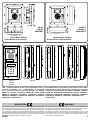
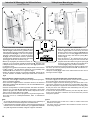
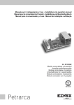
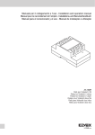
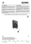
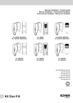
VIDEOKIT Serie VK4K Series VIDEOKIT Mono-familiari e Bi-familiari One Way, Two Way Norme Tecniche Owner’s Manual Videx Electronics S.p.A. Via del Lavoro, 1 63024 Monte Giberto (AP) - Italy Phone +39 0734 631669 - Fax +39 0734 632475 E-Mail [email protected] - Web: www.videx.it Si raccomanda di far installare il presente dispositivo esclusivamente da personale qualificato. We recommend This equipment is installed by a Competent Electrician, Security or Communications Engineer. VK4K, VK4K-S VK4K, VK4K-S Videokit Monofamiliare con videocitofono e telecamera bianco e nero One way videoki with B&W videophone and camera I videokit della serie VK4K fanno parte di una nuova linea che utilizza il posto esterno con design Serie 4000. Il videocitofono fornito a corredo è Serie 3000 in una versione espressamente progettata per questa linea di videokit. L’unità di ripresa ha le dimensioni di un modulo della Serie 4000 ed è corredato dal relativo supporto da incasso (VK4K) o superficie (VK4K-S) in base alla versione del kit. Grazie all’impiego della tecnologia a microprocessore sia nel modulo portiere elettrico - unità di ripresa che nel videocitofono, i kit di questa linea offrono numerose funzioni innovative tra le quali troviamo: •Segnalazioni acustiche e visive in merito al funzionamento del sistema in aiuto degli utenti diversamente abili; •Possibilità di utilizzo della serratura tramite relè a contatti puliti o scarica capacitiva; •Possibilità di collegare un pulsante per l’apertura diretta della porta d’ingresso; •Possibilità di programmazione dei tempi d’apertura porta e conversazione; •Possibilità di collegare fino a 4 ingressi con l’ausilio di relè d’asservimento Art.506N; •Predisposizione per il collegamento del modulo display Art.4820 e del lettore chiavi di prossimità stand-alone Art.4850; •Possibilità di programmare il numero di squilli da un minimo di 2 ad un massimo di 8; •Ingresso per chiamata di piano-locale; •Possibilità di monitorare lo stato d’apertura-chiusura della porta tramite apposito LED presente sul videocitofono (è richiesto un conduttore addizionale dalla porta verso il videocitofono); •Possibilità di programmare la funzione privacy da un minimo di 15 minuti ad un massimo di 8 ore; •Predisposizione per il collegamento facilitato di un citofono in parallelo (max 2 indipendentemente dal numero di videocitofoni in parallelo); •Possibilità di collegare fino a 4 videocitofoni in parallelo con funzione di intercomunicazione; •Auto-accensione selettiva in caso di più ingressi; •Brandeggio telecamera regolabile sia verticalmente che orizzontalmente con un’escursione massima di 10º. Il kit comprende: 1 Unità di ripresa Art.4833-1. L’unità incorpora una telecamera bianco e nero CCD autofocus di alta qualità, i LED d’illuminazione agli infrarossi, la circuiteria di amplificazione audio e il portiere elettrico con un pulsante di chiamata; 1 Supporto da incasso ad 1 modulo Art.4851 (nella versione da superficie VK4K-S questo articolo è rimpiazzato dalla relativa scatola da superficie Art.4881); 1 Videocitofono Art.3356 Bianco & Nero con schermo piatto da 4” completo di piastra di fissaggio a parete e scheda di connessione Art.3980; 1 Trasformatore di alimentazione Art.850K (Cont. DIN 5 Moduli tipo A). The VK4K series is a new range of videokits that use the 4000 series external door station and the 3000 series videophone which is specific for this range of videokit. The camera / audio unit is the size of a single 4000 series module and is available in either flush (VK4K) or surface (VK4K-S) mounting versions. As a result of using microprocessor technology in the door panel and videophone, a number of additional features have been added to enhance the operation of the videokits and give greater feedback to the visitor and user. •Disability friendly, visual and acoustic signals from the door panel to inform the visitor of call status (call made, ringing, speak, door open). •Programmable door open and conversation time. •Expandable to 4 entrance panels (requires an additional relay Art.506N for each entrance panel). •Connections for a push to exit button. •Two methods of operating the electric lock:- 1) Dry contact relay, 2) capacitor discharge circuit. •Facility for the connection of a codelock Art.4800, display module Art.4820, stand-alone proximity reader Art. 4850 or stand-alone biometric reader Art. 4821 etc. •Programmable number of call tone rings from 2 to a maximum of 8. •Input for local door bell push button. •Programmable timed privacy function from 15 minutes to a maximum of 8 hours. •Door open status LED (additional wire required from the door to the videophone) •Up to 4 videophones can be connected in parallel, all with intercommunication facility. •Videophones can have a maximum of two additional audio telephone handsets connected in parallel. •Camera recall on all systems, with selective recall on systems with multiple entrances. •Door panel camera can be adjusted horizontally and vertically (10 degrees). CVK4K, CVK4K-S Videokit Monofamiliare con videocitofono e telecamera a colori The kit comprises of. 1 Camera unit Art.4833-1. The unit includes a high quality B&W CCD camera with auto iris lens, infrared LEDs for illumination, audio amplifiers and one button speaker unit; 1 Module front support with flush mounting box Art.4851 (the surface version of the kit VK4K-S includes the relevant surface mounting box Art.4881); 1 B&W videophone Art.3356 with 4” flat screen complete with mounting plate and PCB connection Art.3980; 1 Power transformer Art.850K boxed in 5 Module A Type DIN BOX. CVK4K, CVK4K-S One way videoki with colour videophone and camera Come i kit VK4K e VK4K-S, ma con videocitofono a colori Art.3456 con monitor As VK4K and VK4K-S but with Art.3456 colour videophone with 3,5” LCD TFT TFT da 3,5” e unità di ripresa Art.4833colour con telecamera a colori e LED monitor and colour camera unit Art.4833colour with white light illumination LEDs. d’illuminazione ad emissione di luce bianca. VK4K/MV, VK4K-S/MV Videokit Monofamiliare con videocitofono+memoria e telecamera bianco e nero VK4K/MV, VK4K-S/MV One way videokit with B&W videophone with memory and camera Come i kit VK4K e VK4K-S, ma con videocitofono bianco e nero Art.3556 com- As VK4K and VK4K-S but with B&W videophone Art.3556 with memory board and special power supply Art.850K/MV. pleto di memoria video ed alimentatore specifico Art.850K/MV. VKC4K, VKC4K-S, CVKC4K, CVKC4K-S Videokit Monofamiliare (bianco e nero o colori) più tastiera digitale VKC4K, VKC4K-S, CVKC4K, CVKC4K-S One way videokit (colour or B&W) plus a codelock module Come i kit VK4K, VK4K-S, CVK4K e CVK4K-S ma con supporto da incasso a 2 As VK4K,VK4K-S, CVK4K and CVK4K-S but with flush mounting box Art.4852, moduli Art.4852, modulo tastiera digitale a codice stand-alone Art.4800. L’uten- stand-alone codelock module Art.4800. The user can open the door from outside by typing the relevant access code into the keypad. te può aprire la porta digitando l’apposito codice tramite la tastiera. VKX4K, VKX4K-S, CVKX4K, CVKX4K-S VKX4K, VKX4K-S, CVKX4K, CVKX4K-S Videokit Monofamiliare (bianco e nero o colori) più lettore chiavi di prossimità One way videokit (colour or B&W) plus a proximity key reader module Come i kit VK4K, VK4K-S, CVK4K e CVK4K-S ma con supporto da incasso a 2 moduli Art.4852, modulo lettore chiavi di prossimità stand-alone Art.4850 e 3 chiavi di prossimità in formato card Art.955/C. L’utente può aprire la porta avvicinando la propria chiave di prossimità al lettore. As VK4K,VK4K-S, CVK4K and CVK4K-S but with flush mounting box Art.4852, stand-alone proximity keys reader module Art.4850 and 3 proximity keys card format Art.955/C. The user can open the door from the outside by simply presenting a card/fob to the external reader. VKFP4K, VKFP4K-S, CVKFP4K, CVKFP4K-S VKFP4K, VKFP4K-S, CVKFP4K, CVKX4K-S Come i kit VK4K, VK4K-S, CVK4K e CVK4K-S ma con supporto da incasso a 2 moduli Art.4852 e modulo lettore d’impronte stand-alone Art.4821. L’utente può aprire la porta d’ingresso utilizzando semplicemente le proprie dita. Non sarà più possibile dimenticare le chiavi di casa. As VK4K,VK4K-S, CVK4K and CVK4K-S but with flush mounting box Art.4852 and a stand-alone fingerprint reader module Art.4821. The user can open the door from the outside simply by swiping their finger on the reader. No door keys, codes or fobs to forget. Videokit Monofamiliare (bianco e nero o colori) più lettore d’impronte 2 One way videokit (colour or B&W) plus a fingerprint reader module VK4K VK4K CVK4K VK4K/MV VK4K-S CVK4K-S VK4K/MV-S Flush Door Station Posto Esterno da Incasso 24 VKC4K VKX4K VKFP4K 45 51 VKC4K Tutti i videokit indicati di lato sono disponibili anche in versione bi-familiare con 2 videocitofoni, 2 trasformatori e unità di ripresa a 2 pulsanti Art.4833‑1D: VK4K-2, VK4K-2S, CVK4K-2, CVK4K-2S, VK4K-2/MV, V K4K‑2S/MV, VKC4K-2, VKC4K-2S, CVKC4K-2, CVKC4K-2S, VKX4K-2, VKX4K‑2S, CVKX4K-2, CVKX4K-2S, VKFP4K-2, VKFP4K‑2S, CVKFP4K-2, CVKFP4K-2S. MARCATURA La marcatura CE di conformità indica che il prodotto soddisfa i requisiti delle Direttive della Comunità Economica Europea in vigore (in particolare quelle 73/23/ CEE e 93/68/CEE e Compatibilità elettromagnetica 89/336) ad esso applicabili. La marcatura CE, apposta sui prodotti dal fabbricante (o da un suo mandatario) sotto la propria responsabilità, è stata creata con l’intento di eliminare gli ostacoli alla circolazione dei prodotti all’interno degli Stati membri dell’Unione Europea armonizzando diverse normative a carattere nazionale. VK4K 23 50 45 31 58 263 263 280 45 263 135 Surface Door Station Posto Esterno da Superficie VKX4K VKFP4K All videokit above are available in two button version with 2 videophones, 2 power transformers and camera unit with 2 call push buttons Art.4833‑1D: VK4K-2, VK4K-2S, CVK4K-2, CVK4K-2S, VK4K-2/MV, VK4K‑2S/MV, VKC4K-2, VKC4K-2S, CVKC4K-2, CVKC4K-2S, VKX4K-2, VKX4K-2S, CVKX4K-2, CVKX4K-2S, VKFP4K-2, VKFP4K-2S, CVKFP4K-2 and CVKFP4K‑2S. MARKING CE conformity marking indicates that the product respects the requirements of the applicable European Community Directives in force (specifically 73/23/EEC, 93/68/EEC and the Electromagnetic Compatibility Directive 89/336). CE marking is applied by the manufacturer (or party delegated to do so by the manufacturer) under their own responsibility. It was created to eliminate obstacles to the circulation of products in European Union Member States by harmonising different national standards. 3 VIDEOCITOFONO VIDEOPHONE Pulsanti, LED, Controlli, Impostazioni e Segnali Push Buttons, LEDs, Controls, Settings & Signals Pulsanti Push Buttons Pulsante apri-porta/chiamata intercomunicante. Come pulsante di chiamata intercomunicante è operativo solo quando il sistema è in stand-by. La modalità intercomunicante dipende dalla posizione dello switch 4 dell’SW1: OFF Intercomunicazione solo tra appartamenti - sollevare la cornetta e premere il pulsante chiave per chiamare il videocitofono nell’altro appartamento. Un eventuale tono di occupato segnala che l’altro appartamento è in conversazione con l’esterno. ON Intercomuncazione solo tra videocitofoni dello stesso appartamento - sollevare la cornetta e premere il pulsante chiave 1, 2, 3 o 4 volte per chiamare il videocitofono con indirizzo d’interno 1, 2, 3 o 4. Door-open / intercommunicating call button. Intercommunication only works when the system is in stand-by condition. Switch 4 of the SW1 dipswitch selects the type of intercommunication: Qualsiasi conversazione intercomunicante è sempre interrotta da una chiamata esterna. Pulsante di auto-accensione. In presenza di più ingressi, premere 1, 2, 3 o 4 volte per attivare l’ingresso 1, 2, 3 o 4. Pulsante di servizio. Quando premuto collega internamente il relativo morsetto “17” con il morsetto comune “18”. Pulsante di servizio. Quando premuto collega internamente il relativo morsetto “16” con il morsetto comune “18”. Pulsante “privacy” ON-OFF. Il pulsante attiva/disattiva la funzione “privacy”, in ogni caso la funzione si disattiva automaticamente allo scadere del tempo programmato. Any intercommunicating conversation is always interrupted by an external call (i.e. External calls take priority). Camera recall button. In case of more entrances, press the button 1, 2, 3 or 4 times to switch on door unit with ID 1, 2, 3 or 4. Service push button. When pressed shorts terminal “17” to the common terminal 18. Service push button. When pressed shorts terminal “16” to the common terminal 18. Privacy ON-OFF button. Enable/Disable the privacy service, the service is automatically disabled when the programmed privacy time expires. OFF ON Intercommunication between two apartments - pick up the handset and press the key button to call the videophone(s) in the other apartment. A busy tone will signal that the other videophone is in conversation with the doorstation and so cannot be called. Intercommunication between videophones in the same apartment - pick up the handset and press the key button one, two, three or four times to call videophone with extension address 1, 2, 3 or 4 (Set on dip-switch 2&3 of SW1). LED LEDs LED “PRIVACY ON”. Acceso quando il servizio è abilitato Red “PRIVACY ON” LED. The LED is on when the function is enabled. LED “DOOR OPEN”. Fatti gli opportuni collegamenti, questo led indica lo “DOOR OPEN” LED. If the required connections are made, the LED shows Green stato della porta: acceso = aperta, spento = chiusa. the open/close status of the door: ON = Open, OFF = Closed. Controlli Controls Regolazione volume (3 livelli) della nota di chiamata. Regolazione del contrasto. Call tone volume control (3 levels). Contrast control. To adjust move from left to right. Regolazione della luminosità. Brightness control. To adjust move from left to right. Impostazioni (Dip-Switch) Settings (Dip-Switches) L’impostazione del videocitofono viene eseguita tramite i 2 dip-switch accessibili The videophone setup is carried out by the 2 dip-switches accessible from the dalla parte posteriore dello stesso. rear of the videophone. DIP-SWITCH a 8 VIE (SW1) 8 WAY DIP-SWITCH (SW1) Switch 1Indirizzo d’Appartamento Switch 1Apartment Address OFF1 OFF1 =ON =OFF 1 2 3 4 5 6 7 8 ON2 ON2 ON ON Switch 2,3 Indirizzo Interno OFFOFF1 ONOFF2 OFFON3 ONON4 Switch 4Intercomunicazione OFFtra i videocitofoni dei due appartamenti ONtra i videocitofoni dello stesso appartamento 4 =ON =OFF ON 1 2 3 4 5 6 7 8 ON =ON ON =OFF SW1 SW1 1 2 3 4 5 6 7 8 ON Switches 2,3 Extension Address OFFOFF1 ONOFF2 OFFON3 ONON4 Switch 4Intercommunication OFFBetween videophones of the two apartment ONBetween videophones in the same apartment SW1 VK4K Switch 5,6 Numero di squilli OFFOFF2 ONOFF4 OFFON6 ONON8 Switch 7,8 Durata Privacy OFFOFF15minuti ONOFF1ora OFFON4ore ONON8ore =ON =OFF ON =ON =OFF ON DIP-SWITCH a 2 VIE (SW2) Il dip-switch a 2 vie serve per adattare l’impedenza del segnale video. L’impostazione di default è “ON” per entrambi gli switch (75 Ohm): in presenza di più videocitofoni collegati in parallelo (senza distributore video), gli switch devono rimanere entrambi ad “ON” solo per l’ultimo (in ordine di connessione) videocitofono, mentre per tutti gli altri devono essere impostati entrambi ad “OFF”. 1 2 3 4 5 6 7 8 ON 1 2 ON SW2 SW1 1 2 3 4 5 6 7 8 ON =ON SW1 =OFF ON 1 2 ON SW2 Switches 5,6 Number of Rings OFFOFF2 ONOFF4 OFFON6 ONON8 Switches 7,8 Privacy duration time OFFOFF15 minutes ONOFF1 hours OFFON4 hours ONON8 hours 2 WAY DIP-SWITCH (SW2) The two way dip-switch adjusts the impedance of video signal. The default setting is “ON” for both switches (75 Ohm): when there are more videophones in parallel connection (without video distributor) both switches must be “ON” only on the last videophone (looking at the connection order) while for all other videophones both switches must be set to “OFF”. Segnali (Art.3980) Signals (Art.3980) Uscita fonia proveniente dal microfono della cornetta e segnale dati (12V circa in stand-by, 5V circa in conversazione) Ingresso fonia verso l’altoparlante della cornetta (12V circa in stand-by, 3V circa in conversazione) Ingresso fonia verso l’altoparlante del citofono collegato in parallelo (12V circa in stand-by e 3V circa in conversazione) Segnale video bilanciato 1 sinc.- 1 Segnale video bilanciato 2 sinc.+ 5 Balanced video signal 2 sync.+ Ingresso d’alimentazione – riferimento di massa 6 Power supply ground input Ingresso d’alimentazione 12Vdc 150mA per videocitofono con memoria video (solo per il videocitofono 3556) Ingresso/Uscita 20Vdc (come ingresso 16÷20Vdc 0,5A – come uscita 20Vdc 0,5A max) Ingresso d’alimentazione 24Vac 1A max 7 12Vdc 150mA power input to supply memory board, only on 3556 videophone 20Vdc Input/Output (As input 16÷20Vdc 0,5A – as output 20Vdc 0,5A max) 2 3 4 8 9 Speech line output from handset’s microphone and data signal (About 12V in stand-by, about 5V in conversation) Speech line input toward the handset’s loudspeaker (About 12V in stand-by, about 3V in conversation) Speech line input toward the loudspeaker of the parallel telephone (About 12V in stand-by, about 3V in conversation) Balanced video signal 1 sync.- 24Vac 1A max power input Ingresso d’alimentazione 0Vac 10 0Vac power input Uscita riferimento di massa citofono in parallelo 11 Output ground for parallel telephone Uscita tono di chiamata per citofono in parallelo 12 Output call tone for parallel telephone Ingresso comando apri-porta citofono in parallelo 13 Input for door-open command from parallel telephone Ingresso 12Vdc per LED di segnalazione porta aperta 14 12Vdc input for door-open LED Ingresso per chiamata locale (5V stand by, 0V in funzione) 15 Local call input Contatto pulsante “S” riferito al morsetto “18” a pulsante premuto 16 “S” button contact shorts to terminal “18” when pressed Contatto pulsante “ 17 “ 18 Common contact for “S” and “ ” riferito al morsetto “18” a pulsante premuto Contatto comune pulsanti “S” e “ ” * Rimuovere la resistenza R1 se presente VK4K ”button contact shorts to terminal “18” when pressed ”buttons * Remove R1 resistor if present 5 PORTIERE ELETTRICO SPEAKER UNIT LED, Controlli, Impostazioni e Segnali LEDs, Controls, Settings & Signals ON H L 1 2 3 4 sw +V - 12Vout 1 2 V2 V1 BS SL PTE C NC NO LED J1 J2 DATA LEDs Se acceso, indica che non è possibile chiamare a causa di una chiamata o conversazione in corso dal posto esterno in uso o da un altro posto esterno in caso di sistemi a più ingressi. Il LED si spegne con l’impianto a riposo (nessuna conversazione o chiamata in corso). Se acceso, indica che è in corso la chiamata dal posto esterno che si sta utilizzando. Il LED si spegne alla risposta dell’utente chiamato o al raggiungimento del numero di squilli programmati. Se acceso, indica che è in corso la chiamata dal posto esterno che si sta utilizzando. Il LED si spegne alla risposta dell’utente chiamato o al raggiungimento del numero di squilli programmati. Se acceso, indica che l'utente chiamato ha aperto la porta. Il LED resta acceso per tutto il “tempo d'apertura porta” programmato. When illuminated, indicates that it is not possible to make a call because a call or a conversation is in progress (from the outdoor station from which you are calling or from another outdoor station on systems with multiple entrances). The LED will be off when the system is in stand-by. If illuminated, indicates that the call from the outdoor station is in progress. The LED will switch OFF when the call is answered or after the programmed number of rings. If illuminated, indicates that it is possible to speak because the call has been answered. The LED will switch OFF at the end of a conversation (or at the end of the conversation time). If illuminated, indicates that the door lock has been operated. It will switch OFF at the end of the programmed “door opening” time. Controlli (volume microfono e speaker) Controls (speaker & microphone volume) Trimmer di regolazione del volume dello speaker. Ruotare in senso orario per aumentare o antiorario per diminuire. Trimmer di regolazione del volume del microfono. Ruotare in senso orario per aumentare o antiorario per diminuire. Trimmer to adjust the speaker volume. Rotate clockwise to increase or anticlockwise to decrease. Trimmer to adjust the microphone volume. Rotate clockwise to increase or anticlockwise to decrease. Impostazioni (Dip-switch e Jumper) Settings (dip-switch & Jumpers) DIP-SWITCH a 4 VIE 4 WAY DIP-SWITCH I primi 2 switch permettono di configurare l’indirizzo del posto esterno: l’indirizzo First two switches are used to set the speaker unit address: the speaker unit adè necessario per l’auto-accensione selettiva in caso di 2 o più posti esterni dress is required for camera recall operation on 2 or more entrance systems. Switch 1,2Indirizzo Unità Switches 1,2Unit Address ON ON OFFOFF1 OFFOFF1 =ON =OFF ONOFF2 ONOFF2 1 2 3 4 OFFON3 OFFON3 sw ONON4 ONON4 Switch 3Conversation Time Switch 3Tempo di Conversazione ON ON OFF60 seconds OFF60 secondi =ON =OFF ON120 seconds ON120 secondi 1 2 3 4 sw Switch 4 Tempo d’apertura porta (J2 posizione “L”) OFF2 secondi ON6 secondi ON ON =ON =OFF 1 2 3 4 sw Switch 4 Door opening time (J2 = “L” position) OFF2 seconds ON6 seconds Jumper J1, J2 Jumpers J1, J2 H J1 Position Call reassurance tone volume Posizione J1 Volume tono di conferma chiamata HHigh HAlto L LLow LBasso J1 J2 H J2 Position Door open relay operating mode Posizione J2 Funzionamento relè apri-porta HCapacitor discharge HScarica capacitiva L LDry contacts LContatti puliti J1 J2 Quando la modalità è impostata su “scarica capacitiva”, un terminale della ser- When the door open relay operating mode is set to “capacitor discharge”, one ratura va collegato a massa, mentre l’altro va collegato al morsetto “NO” che terminal of the electric lock must be connected to ground while the second must fornisce una tensione temporanea al ricevimento del comando d’apertura porta. be connected to “NO” terminal. The “NO” terminal will supply a temporary voltNella modalità contatti puliti, al ricevimento del comando d’apertura porta il con- age when the speaker unit receives the door open command. In “dry contacts” mode the “NO” terminal is internally linked to “C” terminal when the speaker unit tatto “NO” chiude verso “C”. receive the door open command. 6 VK4K Segnali (Morsettiera) Signals (Terminals) Ingresso d’alimentazione 16÷20Vdc +V Alimentazione riferimento di massa - Uscita 12Vdc. 0,3A max. per alimentazione accessori Ingresso fonia verso l’altoparlante del portiele elettrico e segnale dati (12V circa in stand-by, 5V circa in conversazione) Uscita fonia dal microfono del portiere elettrico (12V circa in stand-by, 3V circa in conversazione) Uscita segnale video bilanciato sinc.- 12Vout 1 2 V1 Power input 16÷20Vdc Power input ground 12Vdc. 0,3A max. output to supply accessiories Speech line input toward the loudspeaker and data signal (about 12V in stand-by, about 5V with a conversation in progress) Speech line output from the microphone (about 12V in stand-by, about 3V with a conversation in progress) Balanced video signal sync.- Uscita segnale video bilanciato sinc.+ V2 Balanced video signal sync.+ Ingresso/Uscita segnale di linea occupata (12Vcirca in stand-by, 0V circa con chiamata in corso) Uscita segnale per attivazione relè scambio video (attivo basso con chiamata in corso) Ingresso attivo basso di comando diretto per il relè apri-porta BS Input/Output busy signal (about 12V in stand-by, about 0V with a call in progress) Active low output to enable the enslavement relay for video signal exchange (active with a call in progress) Active low input to control directly the door open relay Relè apri-porta contatto comune SL PTE C Door open relay common contact Relè apri-porta contatto normalmente chiuso NC Door open relay normally closed contact Relè apri-porta contatto normalmente aperto NO Door open relay normally open contact VK4K 7 Collegamento alla Rete Elettrica, Installazione dell’Alimentatore Connection to Mains, Power Supply Mounting Instructions La realizzazione dell’impianto deve essere eseguita nel rispetto delle vigenti normative nazionali, in particolare si raccomanda di: •Collegare l’impianto alla rete elettrica tramite un dispositivo di interruzione omnipolare che abbia una distanza di separazione del contatto di almeno 3mm per ciascun polo e che sia in grado di disconnettere tutti i poli simultaneamente; •Il dispositivo di interruzione omnipolare deve essere posizionato in un luogo tale da consentirne un facile accesso in caso di necessità. The system must be installed according to national rules in force, in particular we recommend to: •Connect the system to the mains through an all-pole circuit breaker which shall have contact separation of at least 3mm in each pole and shall disconnect all poles simultaneously; •The all-pole circuit breaker shall be placed for easy access and the switch shall remain readily operable. INSTALLAZIONE DELL’ALIMENTATORE •Rimuovere i coperchi copri-morsetti svitando le relative viti e tirandoli verso l’alto; •Fissare l’alimentatore su barra DIN o direttamente a parete utilizzando le viti ed i relativi tasselli ad espansione forniti a corredo; •Togliere la tensione di rete tramite il dispositivo sopra indicato ed eseguire le connessioni come previsto dagli schemi proposti (la connessione verso la rete va effettuata in base alla tensione disponibile 127 o 230Vac). •Verificare che non vi siano errori di connessione e che i fili siano ben serrati nei morsetti; •Inserire a scatto i coperchi copri-morsetti e fissarli tramite le relative viti; •Eseguiti tutti i collegamenti, dare tensione all’impianto. POWER SUPPLY INSTALLATION •Remove the terminal side covers by unscrewing the retaining screws; •Fix the power supply to a DIN bar or directly to the wall using two expansion type screws; •Switch off the mains using the circuit breaker mentioned above and then make the connections as shown on the installation diagrams; •Check the connections and secure the wires into the terminals; •Replace the terminal covers and fix them using the relevant screws; •When all connections are made, restore the mains. Installazione Posto Esterno Door Station Mounting POSTO ESTERNO DA SUPERFICIE 1. Appoggiare la scatola da superficie alla parete lasciando circa 165-170cm tra la parte alta della scatola ed il terreno come mostrato in figura 1 quindi prendere i riferimenti per i fori di fissaggio tenendo presente che il gruppo di fili e (fig.2) deve passare attraverso l’apertura d presente sulla scatola da superficie. Se non indicato, il verso di montaggio della scatola deve essere tale da far rimanere la cerniera sulla sinistra; 2. Come mostrato in figura 2, realizzare i fori di fissaggio a, inserire al loro interno i tasselli ad espansione b e, facendo passare i fili di collegamento e attraverso l’apertura d, fissare la scatola da superficie c alla parete utilizzando le viti f; 3. Inserire il modulo g nel supporto h come mostrato in figura 3; 4. Prima di agganciare alla scatola da superficie il supporto completo di modulo, inserire i fermi anti-effrazione i come mostrato in figura 4; 5. Muovendo il supporto h come mostrato dalle frecce di figura 5, procedere all’aggancio dello stesso alla scatola da superficie c. Il perno l deve inserirsi nel relativo alloggiamento m come mostrato in figura 6; 6. Come mostrato in figura 7, tirare il supporto moduli h indietro compiendo contemporaneamente un leggero movimento a sinistra come suggerito dalle frecce; 7. Come mostrato in figura 8, ruotare il supporto moduli h nella direzione consigliata dalla freccia e provvedere ad agganciare il fermo n all’alloggiamento m del perno. Assicurato il supporto alla scatola da superficie, svolgere le seguenti operazioni: •eseguire le opportune configurazioni dell’unità tramite i 2 jumper ed il dipswitch a 4 vie accessibili dall’apertura o •effettuare i necessari collegamenti con l’ausilio del giravite (lato piatto della lama) fornito a corredo; •regolare l’angolo di ripresa della telecamera agendo sulla vite p; 8. Ad impianto testato e funzionante, procedendo a ritroso delicatamente, chiudere e fissare il supporto moduli alla scatola da superficie utilizzando il giravite s (lato torx della lama) e le viti q come mostrato in figura 9. Nota bene: non serrare le viti più del necessario. SURFACE DOOR STATION 1. Place the surface box against the wall (165-170cm between the top of the box and the floor lever as show in figure 1) and mark the fixing holes for the wall plugs and hole for the cables e (fig.2). Observe the orientation of the box with the hinge on the left; 2. As shown on figure 2, drill the fixing holes a, insert the wall plugs b and feed the cables e through the surface box opening d, fix surface box c to the wall using the screws f; 3. Hook the module g in the support frame h as shown in figure 3; 4. Before the installation of the module support frame, fit the two anti-tampering locks provided as shown in figure 4; 5. As shown in figure 5, hook the module support frame h (complete with modules) to surface box c moving the frame as suggested from pointers. Ensure that the pivot l (fig.5) goes inside the relevant housing m as shown in figure 6. 6. As shown in figure 7, pull back the module support frame h while moving it slightly to the left as suggested by the pointers; 7. As shown in figure 8, open the module support frame h as suggested by the pointer, hook the hinge lock n to the hinge m. When the support frame is hooked to the surface box, do the following operations: •make the required settings operating the two jumpers and the 4 way dipswitch accessible from the opening o (fig.8) •make the required connections using the screwdriver provided (blade flat side); •adjust the camera viewing angle by operating the screw p (fig.8); 8. When the system has been tested and is working correctly, move back the module support frame carefully, fix it to the surface box using the provided screwdriver s (blade torx side) and the pin machine torx screws q as shown in figure 9. Note: do not over tighten the screws more than is necessary. FLUSH DOOR STATION POSTO ESTERNO DA INCASSO If the door station is a flush, carry out the following: Se il posto esterno è da incasso occorre procedere come di seguito indicato: 1. Dopo aver opportunamente protetto i fori di fissaggio per il supporto moduli, 1. Protect the module support frame fixing holes from dust then embed the back box into the wall (165-170cm between the top of the box and the floor level as murare la scatola da incasso ad una altezza tale da avere circa 165-170cm shown on the figure 1) feeding the cables e (fig.2) through a previous opened tra la parte alta della scatola e il terreno avendo cura di far passare il gruppo hole in the box. Observe the direction of the box ensuring the hinge is di fili e (fig.2) attraverso uno dei fori precedentemente aperti sul fondo della on the left and take care that the box profile is in line with the finished scatola. Se non indicato sul fondo della scatola, il verso di muratura wall profile; deve essere tale da lasciare la cerniera sulla sinistra. Fare attenzione 2. Continue from step 3 of surface mounting, but at step 6 hook the hinge lock affinché la scatola sia murata a filo muro finito; n as shown on figure 10. 2. Proseguire dal passo 3 della installazione da superficie tenendo presente che al punto 7 il fermo n va agganciato come mostrato in figura 10. Notes Note La lama del giravite fornito a corredo ha due punte, una piatta ed una torx. Sfila- The screwdriver’s blade has two sides, one flat and one torx, to select one of them unplug the blade from the screwdriver body and plug it into the required re la punta e reinserirla nel manico scegliendo il lato desiderato side. 8 VK4K VK4K 9 Istruzioni di Montaggio del Videocitofono Videophone Mounting Instructions Art.3356, 3456 e 3556 Art.3356, 3456 and 3556 PIASTRA DI FISSAGGIO E SCHEDA DI CONNESSIONE MOUNTING PLATE & PCB CONNECTIONS •Appoggiare al muro la piastra di fissaggio A come •Place the mounting plate A against the wall as indicato in fig.6 (135cm da terra); prendere i riferishown in fig.6 (135cm from floor level); and mark menti dei quattro fori per l’inserimento dei 4 tasselthe fixing holes for the four wall plugs B (fig.4) and li ad espansione B (fig.4) e, nel caso si impieghi, for the back box C if used (fig.4) which must be prendere il riferimento per la scatola da incasso flushed into the wall in line with the opening D as C (fig.4), che dovrà essere murata in posizione shown in fig.4. centrale rispetto all’apertura D al fine di agevolare •Once the back box(1) C is flushed into the wall (if used), drill the four fixing holes and insert the wall il passaggio dei fili come mostrato in fig.4. plugs B. Thread the cables through the opening D •Murare (se impiegata) la scatola da incasso(1) C, and fix the mounting plate A to the wall with the 4 eseguire i 4 fori ed inserire i tasselli ad espansione B. Passare i cavi screws E (fig.4), using a Philips screwdriver. nell’apertura D e fissare la piastra A con le 4 viti E (fig.4) utilizzando un giravite a croce. •Fit the PCB F against the mounting plate A as shown in fig.4; insert •Appoggiare la scheda di connessione F sulla piastra A come mostrato the wires(2) (As short as possible) into terminals G-H. Secure them usin fig.4; inserire(2) i fili (che devono essere più corti possibile) nelle ing a terminal screwdriver. morsettiere G ed H e serrare con un giravite a taglio. •Unclip the PCB F (fig.4), rotate it 90º anticlockwise and fit it into its •Fissati i fili, sfilare la scheda di connessione F (fig.4), ruotarla di 90º housing as shown in fig.5. in senso antiorario ed infilarla nella propria sede come mostrato in fig.5. APPLICAZIONE DEL VIDEOCITOFONO ALLA PIASTRA INSTALLING THE VIDEOPHONE ONTO THE MOUNTING PLATE NOTE NOTES •Avvicinare, come da fig.5, il videocitofono L alla piastra A per agevolare la connessione del flat I. •Come mostrato in fig.5 inserire il connettore del flat I, che fuoriesce dalla parte posteriore del videocitofono, nel connettore M della scheda di connessione F. •Facendo corrispondere le 4 fessure presenti sulla base del videocitofono L con i 4 incastri N della piastra A, appoggiare il video sulla piastra e spingerlo verso il basso fino allo scatto, compiendo un movimento come mostrato dalle frecce in fig.5. •Per rimuovere il videocitofono, spingere con un giravite a taglio il dente O verso il muro e, contemporaneamente, tirare il videocitofono verso l’alto. Si consiglia di utilizzare una scatola da incasso (non in dotazione) al fine di contenere l’eventuale lunghezza eccedente dei fili. (2) I collegamenti alla morsettiera devono essere eseguiti rispettando gli schemi forniti a corredo del videocitofono, per applicazioni differenti da quelle degli schemi standard, rivolgersi al proprio rivenditore. (1) 10 •As shown in fig.5, move the videophone L close to the mounting plate A so that the ribbon cable will reach the connector I. •As shown in fig.5, connect the female plug on the ribbon cable I coming from the videophone to the male plug connector M on the PCB F. •Place the videophone L against the 4 hooks N on the mounting plate A and push down: the videophone will automatically lock into place using clasp O as shown in fig.5. •To remove the videophone from the wall, push the clasp O in the direction of the wall with a screwdriver and at the same time push the videophone upwards. We recommend using a back box in order to contain excess wire behind the back plate. (2) The wires must be connected to the terminals as shown on the relevant wiring diagrams. (1) VK4K Sezione Fili e Ricerca Guasti Section of Wires & Troubleshooting Guide SEZIONE FILI Per le connessioni Video e quelle audio suggeriamo di utilizzare delle coppie di fili intrecciati: una coppia per la linea video (morsetti “4” e “5”, segnali “V1” e “V2”) ed una coppia per quella audio (morsetti “1” e “2”, segnali “1” e “2”). SECTION OF WIRES Video connections and Audio connections must be wired in twisted pair : pair the video lines (terminals “4” and “5” signals “V1” and “V2”), pair the audio lines (terminals “1” and “2” signals “1” and “2”). Dal trasformatore al videocitofono max 20 mt.: 2 fili da 1 mm2 Between transformer and videophone 20 mt max: 2 wires 1 mm2 . Dal videocitofono al posto esterno: Between videophone and outdoor station: per VK4K, VKC4K fino a 50m : tutti i fili da 0.35 mm2. da 50 a 100m : fili + e - da 0.75 mm2; tutti gli altri da 0.5 mm2. da 100 a 200m : fili + e - da 1.5 mm2; tutti gli altri da 0.75 mm2. For VK4K, VKC4K up to 50 mt : all wires 0.35 mm2. from 50 to 100 mt : wires + and – 0.75 mm2; other wires 0.5 mm2. from 100 to 200 mt : wires + and – 1.5 mm2; other wires 0.75 mm2 per il CVK4K fino a 50m : fili + e - da 0.5 mm2; tutti gli altri 0.35 mm2. da 50 a 100m : fili + e - da 1 mm2; tutti gli altri 0.5 mm2. da 100 a 200m : fili + e - da 2 mm2; tutti gli altri 0.75 mm2. For CVK4K up to 50 mt : wires + and – 0.5 mm2; other cables 0.35 mm2. from 50 to 100 mt : wires + and – 1 mm2; other cables 0.5 mm2. from 100to 200 mt : wires + and – 2 mm2; other cables 0.75 mm2. RICERCA GUASTI In caso di malfunzionamenti effettuare i seguenti controlli preliminari: •Verificare che i conduttori siano collegati in accordo a quanto indicato nello schema d’istallazione e che questi siano saldamente serrati nei morsetti (videocitofono, portiere elettrico o alimentatore); •Verificare che sia presente la tensione di rete tra i morsetti 230Vac (o 127Vac) e 0 del trasformatore di alimentazione Art.850K; •Verificare la presenza della tensione “24Vac” in uscita dal trasformatore Art.850K. L’eventuale assenza di tensione può essere causata dall’interruzione del fusibile da 1,6A, in tal caso togliere la tensione di rete, accertarsi che non vi siano sovraccarichi o cortocircuiti e sostituire il fusibile con uno uguale o equivalente; •Verificare che la tensione fra i morsetti “+” e “-” del portiere elettrico sia compresa tra 16 e 20Vdc; Se il problema non è tra quelli sopra indicati, consultare la seguente tabella. TROUBLESHOOTING GUIDE In case of system failure, try the following as preliminary checks: •Check that the cables are connected as shown in the installation diagram and that the cables are firmly fixed into the relevant terminals; •Check that the mains voltage is available on terminals 230Vac (or 127Vac) and 0 of the power transformer Art.850K; •Check the 24Vac voltage output of the power transformer Art.850K. If this voltage is not available it could be the 1,6A fuse, in this case remove the mains voltage, remove possible short-circuits or overload sources then replace the fuse with an equal or equivalent one. •Check that the voltage between the terminals “+” and “-” of the speaker unit is between 16 and 20Vdc. If the problem is not listed above, try the tests the following table. Sintomo Causa L’Art.4833 (posto esterno) non • Errato collegamento dei fili tra riesce a far squillare l’interno (il l’Art.4833 e l’Art.3356, verifiLED campana si accende per circare in particolare il filo audio/ ca 2 secondi): dati “1”. • Sezione dei fili inadeguata. • L’indirizzo programmato sul dip-switch dell’Art.3356 non è corretto. La chiamata dal posto esterno • Sezione dei fili inadeguata. funziona correttamente, ma alla risposta cade la comunicazione: Durante la conversazione non è • Sezione dei fili inadeguata. possibile aprire la porta: Durante la conversazione non • Ponticello mobile J2 in posiziosi riesce ad aprire la porta, ma il ne errata. LED chiave dell’Art.4833 si ac- • Fili della serratura collegati in cende: maniera errata. • Tipologia della serratura non adatta. Soluzione • Verificare la connessione dei 6 fili comuni e rimuovere eventuali cortocircuiti. • Aumentare la sezione dei fili o raddoppiarla utilizzandone altri disponibili. • Verificare l’indirizzo del videocitofono. • Aumentare la sezione dei fili o raddoppiarla utilizzandone altri disponibili. • Aumentare la sezione dei fili o raddoppiarla utilizzandone altri disponibili. • Verificare sull’Art.4833 la posizione del ponticello J2. • Verificare il collegamento dei fili. • Verificare che la tipologia di alimentazione della serratura (ac o dc) corrisponda all’impostazione di J2. • Controllare il collegamento del filo “2”. • Regolare opportunamente i trimmer fino a raggiungere il livello di volume desiderato. • Isolare i 6 fili comuni da cavi di rete o altri cavi ad alta tensione. • Canalizzare i fili d’alimentazione del videocitofono separatamente dai 6 fili comuni o insieme per un tratto più breve. Symptom Cause Solution The Art.4833 (door station) is not • Wrong connection between • Check the 6 common wire conable to call the extension (the bell Art.4833 and 3356. nections especially wire “1” LED is switched on for 2 sec- • Cable size too small. (speech line/data). onds): • Programmed videophone ad- • Increase cable size or double dress incorrect. up using two wires for each signal. • Check videophone address on dip-switches. External call works but when an- • Cable size too small. • Increase cable size or double swered the communication fails: section using two wires for each signal. During the conversation it is not • Cable size too small. • Increase cable size or double possible to open the door: section using two wires for each signal. During the conversation it is not • Incorrect position of J2 jumper. • Check J2 position on the Art.4833. possible to open the door but the • Electric lock wires unconnected key LED (Art.4833) switches on or in short. • Check wires connection. for the programmed time: • Wrong electric lock type. • Check that the electric lock type (ac or dc) is suitable for the J2 position chosen. La fonia va dal posto esterno ver- • Filo “2” interrotto o in corto cirso l’interno ma non viceversa: cuito. Volume audio di conversazione • Trimmer di regolazione volume non adeguato: dell’Art.4833 impostati in modo non appropriato. Rumore di fondo durante la con- • I 6 fili comuni sono stati canalizversazione: zati insieme a cavi di rete a 230 o 380Vac. • I fili di alimentazione 24Vac del videocitofono Art.3356 sono stati canalizzati insieme ai 6 fili comuni per un tratto troppo lungo. Non funziona il servizio di “auto- • Premuto il tasto “auto-accen- • Verificare il valore dell’ID del accensione”: sione” per un numero di volte posto esterno (1..4) e premere diverso dall’ID del posto esteril pulsante di “auto-accensione” no da accendere. tante volte quant’è il valore dell’ID. Non funziona la chiamata interco- • Premuto il tasto “chiave” per un • Verificare la corretta impostamunicante: numero di volte diverso dall’inzione degli indirizzi dei videodirizzo del videocitofono da citofoni. chiamare. L’immagine mostrata dal moni- • Segnali V1 e V2 non connessi, • Verificare continuità ed isolator del videocitofono è distorta o scambiati o in corto circuito. mento dei fili V1,V2 riflessa: • Gli switch del dip-switch a 2 vie • Mettere ad on entrambi gli del’ultimo videocitofono non switch. sono entrambi ad ON. • Chiudere le linee passanti • Se presente l’Art.316, linee V1,V2 verso massa con le resipassanti V1 e V2 non chiuse. stenze fornite a corredo Speech only from outside to in- • Wire “2” broken or in short. • Check connection of wire “2”. side: Low volume of speech: • Volume trimmers of Art.4833 • Adjust the trimmers until the rerequire adjustment. quired volume is reached. Non funziona la chiamata di pia- • Connessione errata o pulsante • Controllare la connessione o no: difettoso. sostituire il pulsante. • Check connection or replace the button. VK4K Noise over the speech line during • The 6 common wires cabled • Separate the 6 common wires the conversation: together with 230 or 380Vac from the high voltages cables. power lines. • Separate the 6 common wires • The 6 common wires cabled tofrom the two 24Vac wires or gether with 24Vac videophone cable them together only for a power supply wires. short distance. Camera recall service does not • Camera recall button pressed • Check the ID (1..4) of the door work: for a number of times different station to be recalled and press from the ID of the door station the camera recall button as to be switched on. many time as the ID value. Intercommunicating call does not • ”Key” button pressed for a • Check the address of the videowork: number of times different from phone you are calling and try the videophone address value. again. The video shown on the monitor • V1,V2 signals unconnected, is of a bad quality and the image exchanged or put in short. is distorted or double • The switches of the two way dip-switch are not both in ON position. • V1,V2 of the last Art.316 (if present) not closed with 75 Ohm resistor. Local call does not work: • Wrong connection or call button broken. • Check that the wires are not broken and isolated. • Set both switches in ON position. • Close through V1,V2 of the Art.316 toward the ground with provided resistors. 11 Schemi d’Installazione Installation Diagrams Note e Suggerimenti Notes & Suggestions •Tutti gli schemi, anche se non espressamente indicato, si riferiscono alle ver- •All diagrams refer to all kits versions: flush or surface, color or black & white. sioni da incasso o superficie, bianco e nero o colori dei relativi kit. •Dashed connections refer to optional connections (“Local bell”, “Push to exit” •Le connessioni tratteggiate si riferiscono a collegamenti facoltativi (“Local bell”, & “Door monitor”). “Push to exit” e “Door monitor”). •Some diagrams show how to connect a 12Vdc electric lock: these directions •Alcuni schemi mostrano indicazioni per il collegamento di serrature 12Vdc: tali are suitable for all diagrams in this manual. indicazioni sono da ritenersi valide per ogni schema del presente manuale. Descrizione Schema Lo schema mostra l’installazione di un videokit standard monofamiliare. Tutti gli schemi proposti sono da ritenersi validi per impianti bianco e nero o colori, da incasso o superficie. Lo schema mostra l’installazione di un videokit monofamiliare ed il collegamento di un citofono ed una suoneria addizionali. Le connessioni mostrate per il citofono e la suoneria addizionali sono valide per tutti gli altri schemi del manuale. Lo schema mostra l’installazione di un videokit monofamiliare con l’aggiunta di un secondo posto esterno per la realizzazione di un sistema a 2 ingressi. Da notare l’utilizzo del relè Art.506N per commutare il segnale video tra i 2 ingressi e l’impostazione di un diverso indirizzo per ciascuno dei 2 posti esterni. Lo schema mostra l’installazione di un videokit monofamiliare con l’aggiunta di 3 videocitofoni per la realizzazione di un sistema intercomunicante. Da notare l’utilizzo dell’Art.316 per la distribuzione del segnale video e l’impostazione del dip-switch ad 8 video di ciascun videocitofono: switch 1 ad OFF e switch 4 ad ON ad indicare l’appartamento 1 e l’intercomunicazione tra videocitofoni dello stesso appartamento mentre gli switch 2 e 3 indicano il numero (1..4) di interno. Lo schema mostra l’installazione un videokit monofamiliare con esempi di applicazioni dei pulsanti di servizio e il collegamento di un videocifono addizionale senza l’utilizzo del distributore video Art.316. Da notare la configurazione del dip-switch a 2 vie di ciascun videocitofono: per il primo (in ordine di collegamento) entrambi gli switch sono ad OFF, mentre nel secondo sono entrambi ad ON. Lo schema mostra l’installazione di un videokit bifamiliare. Da notare l’utilizzo del distributore video Art.316 e la configurazione del dip-switch ad 8 vie dei due videocitofoni: switch 1 ad OFF per il videocitofono nell’appartamento 1, ad ON per il videocitofono nell’appartamento 2 e switch 4 ad OFF per entrambi ad indicare intercomunicazione tra appartamenti. Lo schema mostra l’installazione di un videokit bifamiliare con l’aggiunta di un secondo posto esterno per la realizzazione di un sistema a 2 ingressi. Da notare l’utilizzo del relè Art.506N per commutare il segnale video tra i 2 ingressi e l’impostazione di un diverso indirizzo per ciascuno dei 2 posti esterni. Lo schema mostra l’installazione di un videokit bifamiliare con l’aggiunta di 3 posti esterni per la realizzazione di un sistema a 4 ingressi. Da notare la configurazione degli indirizzi dei posti esterni (dip-switch a 4 vie switch 1 e 2) e l’utilizzo degli Art.506N per la commutazione del segnale video tra i 4 ingressi. Lo schema mostra l’installazione di un videocode kit monofamiliare. Questo tipo di kit abbina le prestazioni di un videokit alle funzioni offerte dalle tastiere digitali VIDEX: l’utente, digitando il proprio codice d’accesso, può aprire la porta d’ingresso dall’esterno. Lo schema mostra l’installazione di un videprox kit monofamiliare. Questo tipo di kit abbina le prestazioni di un videokit alle funzioni offerte dal lettore chiavi di prossimità stand-alone VIDEX: l’utente può aprire la porta d’ingresso avvicinando la propria chiave al lettore. Lo schema mostra l’installazione di un videfinger kit monofamiliare. Questo tipo di kit abbina le prestazioni di un videokit alle funzioni offerte dal lettore d’impronte stand-alone VIDEX: l’utente può aprire la porta d’ingresso utilizzando le proprie dita. Lo schema mostra l’installazione del VK4K con memoria video. Viene utilizzato un videocitofono speciale con memoria video Art.3556 ed un alimentatore speciale Art.850K/MV. 12 Nr. Pag Pag.No 13 14 15 16 17 18 Diagram Description The diagram shows the installation of a one way standard videokit. All diagrams shown are valid for B&W or Color systems with surface or flush mount door station. The diagram shows the installation of one way videokit with additional intercom and extension sounder. Connections shown for the intercom and the sounder are suitable for all diagrams in this manual. The diagram shows the installation of one way videokit with the addition of a second door station to make a 2 entrance system. Note the use of the relay Art.506N to switch the video signal between the two door stations and the different address set for each door station. The diagram shows the installation of one way videokit with 3 additional videophones to make an intercommunicating system. Note the use of the Art.316 to distribute the video signal and the setup of the 8 way dip-switch of each videophone: switch 1 OFF and switch 4 ON to point out flat 1 and intercommunication within the same flat while switches 2 and 3 set the extension address (1..4). The diagrams shows the installation of one way videokit with example of how to use the service push button and how to connect an additional videophone without using the video distributor Art.316. Note the setup of the 2 way dip-switch of each videophone: both switches OFF for the first videophone following the connection order, both switches ON for the second videophone (the last). The diagram shows the installation of a two way videokit. Note the use of video distributor Art.316 and the setup of the 8 way dip-switch of each videophone: switch 1 OFF for the videophone in flat 1, switch 1 ON for the videophone in the flat 2, switch 4 OFF for both videophones to set intercommunication between two flats. 19 The diagram shows the installation of a two way videokit with the addition of a second door station to make a two entrance system. Note the use of the relay Art.506N to switch the video signal between the two door stations and the different address set for each door station. 20 The diagram shows the installation of a two way videokit with 3 additional door stations to make a 4 entrance system. Note the different address set for each door station (1..4) and the use of the Art.506N to switch the video signal between the 4 door stations. 21 The diagram shows the installation of one way videocode kit. This videocode kit adds the features offered by a VIDEX digital codelock: the user can open the door from outside by entering the relevant access code on the keypad. 22 The diagram shows the installation of one way videprox kit. This videprox kit adds the features offered by a VIDEX standalone proximity key reader: the user can open the door from outside by simply presenting a card/fob to the external reader. 23 The diagram shows the installation of one way videfinger kit. This videfinger kit adds the features offered by a VIDEX standalone fingerprint reader: the user can open the door from outside simply swiping their finger on the reader. 24 The diagram shows the VK4K version with memory board. It is used a special videophone with memory board Art.3556 and a special power supply Art.850K/MV VK4K Videokit VK4K, CVK4K, VK4K-S, CVK4K-S Videokit VK4K, CVK4K, VK4K-S, CVK4K-S VIDEOCITOFONO / VIDEOPHONE ON 1 2 3 4 5 6 7 8 ON 1 2 Art.3980 1 2 3 4 5 6 7 8 ON 1 2 Art.3356 3456 ON R1 24V 11 12 13 14 15 16 17 18 Local Bell Art.850K 230Vac 0 TRASFORMATORE / TRANSFORMER ART.850K Art.4833-1 1 ON 1 2 3 4 1 2 3 4 SE 12Vdc +V 12Vout 1 2 V2 V1 BS SL PTE C NC NO ON +V 12Vout 1 2 V2 V1 BS SL PTE C NC NO 1 127Vac Push to Exit Using Electric Lock 12Vdc 0.3A Max Con serratura elettrica 12Vdc 0.3A Max Art.4833-1 1 2 3 4 5 6 7 8 9 10 SE 12V AC Door Monitor Title: Data creazione: Titolo: Data modifica: VK4K, VK4K-S, CVK4K, CVK4K-S VK4K, VK4K-S, CVK4K, CVK4K-S Videx Electronics S.p.A. Via del Lavoro 1, 63020 Monte Giberto (AP) Phone: +39 0734 631669 - Fax +39 0734 631669 VK4K www.videx.it - [email protected] 08/01/2008 08/01/2008 Notes: Autore: Note: Cod.File: . . Foglio 1/1 Marco Rongoni vk4k-019.dwg 13 Videokit VK4K, CVK4K, VK4K-S, CVK4K-S con accessori addizionali Videokit VK4K, CVK4K, VK4K-S, CVK4K-S with additional accessories VIDEOCITOFONO / VIDEOPHONE ON 1 2 3 4 5 6 7 8 ON 1 2 Art.3980 1 2 3 4 5 6 7 8 ON 1 2 Art.3356 3456 ON R1 1 2 3 4 5 6 7 8 9 10 24V 11 12 13 14 15 16 17 18 Local Bell 230Vac 0 ART.850K SUONERIA AGGIUNTIVA / ADDITIONAL SPEAKER ART.512A 4 6 1 4 GREEN RED VOL.REG. BLACK YELLOW Art.3111 2 1 3 5 8 9 Push to Exit Art.4833-1 Using Electric Lock 12Vdc 0.3A Max Con serratura elettrica 12Vdc 0.3A Max 1 ON 1 2 3 4 1 2 3 4 SE 12Vdc +V 12Vout 1 2 V2 V1 BS SL PTE C NC NO ON +V 12Vout 1 2 V2 V1 BS SL PTE C NC NO 1 127Vac TRASFORMATORE / TRANSFORMER CITOFONO Addizionale / Additional INTERCOM Art.4833-1 Art.850K SE 12V AC Door Monitor Title: Data creazione: Titolo: Data modifica: VK4K, VK4K-S, CVK4K, CVK4K-S Plus additional accessories VK4K, VK4K-S, CVK4K, CVK4K-S più accessori addizionali Videx Electronics S.p.A. Via del Lavoro 1, 63020 Monte Giberto (AP) Phone: +39 0734 631669 - Fax +39 0734 631669 14 www.videx.it - [email protected] 08/01/2008 08/01/2008 Notes: Autore: Note: Cod.File: . . Foglio 1/1 Marco Rongoni vk4k-001.dwg VK4K Videokit VK4K, CVK4K, VK4K-S, CVK4K-S Videokit VK4K, CVK4K, VK4K-S, CVK4K-S con posto esterno addizionale - sistema a 2 ingressi with additional door station - two entrances system VIDEOCITOFONO / VIDEOPHONE ON 1 2 3 4 5 6 7 8 ON 1 2 Art.3980 1 2 3 4 5 6 7 8 ON 1 2 Art.3356 3456 ON R1 1 2 3 4 5 6 7 8 9 10 24V 11 12 13 14 15 16 17 18 Local Bell Art.850K 230Vac 0 127Vac TRASFORMATORE / TRANSFORMER ART.850K 1 ON SE 12Vdc 1 2 3 4 +V 12Vout 1 2 V2 V1 BS SL PTE C NC NO Art.4833-1 Using Electric Lock 12Vdc 0.3A Max Con serratura elettrica 12Vdc 0.3A Max Door Monitor Door Monitor SE 12V AC 3 2 2 ON 1 NC2 CO2 NO1 NC1 C01 1 ON 1 2 3 4 +V 12Vout 1 2 V2 V1 BS SL PTE C NC NO 1 2 3 4 NO2 Art.4833-1 4 +V 12Vout 1 2 V2 V1 BS SL PTE C NC NO Art.4833-1 5 Art.506N SE 12V AC Push to Exit Push to Exit Title: Data creazione: Titolo: Data modifica: VK4K-1, VK4K-1S Plus additional door station (two entrances system) VK4K-1, VK4K-1S con posto esterno addizionale (sistema a due ingressi) Videx Electronics S.p.A. Notes: The two door stations are set with different ID Via del Lavoro 1, 63020 Monte Giberto (AP) Phone: +39 0734 631669 - Fax +39 0734 631669 VK4K www.videx.it - [email protected] Note: I due posti esterni sono impostati con indirizzi differenti 08/01/2008 27/03/2007 Foglio 1/1 Autore: Marco Rongoni Cod.File: vk4k-005.dwg 15 Videokit VK4K, CVK4K, VK4K-S, CVK4K-S SE 12V AC ON 1 Door Monitor 11 12 13 14 15 16 17 18 1 2 3 4 5 6 7 8 9 10 R1 ON Local Bell 1 2 11 12 13 14 15 16 17 18 1 2 3 4 5 6 7 8 9 10 24V Art.850K 230Vac 0 R1 Art.3980 127Vac ON ON 1 2 11 12 13 14 15 16 17 18 1 2 3 4 5 6 7 8 9 10 Art.316 Art.850K 230Vac 0 127Vac R1 Art.3980 - + V1 V2 - + V1a V2a - + V1b V2b 24V - + V1 V2 - + V1d V2d - + V1c V2c 2x75 Local Bell 1 2 3 4 5 6 7 8 ON ON 1 2 SE 12Vdc Local Bell 1 2 3 4 5 6 7 8 11 12 13 14 15 16 17 18 1234 ON 1 2 3 4 5 6 7 8 ON 1 2 Art.3356 3456 ON 1 R1 Art.3980 127Vac Using Electric Lock 12Vdc 0.3A Max Con serratura elettrica 12Vdc 0.3A Max 1 2 3 4 5 6 7 8 9 10 Art.850K 230Vac 0 +V 12Vout 1 2 V2 V1 BS SL PTE C NC NO VIDEOCITOFONO-4 / VIDEOPHONE-4 1 2 3 4 5 6 7 8 VIDEOCITOFONO-3 / VIDEOPHONE-3 Art.3980 127Vac ON VIDEOCITOFONO-2 / VIDEOPHONE-2 Art.850K 230Vac 0 Art.4833-1 24V 24V ON 1 2 3 4 5 6 7 8 ON 1 2 Art.4833-1D VIDEOCITOFONO-1 / VIDEOPHONE-1 1234 with 3 additional videophones - intercommunicating system Local Bell con 3 videocitofoni addizionali - sistema intercomunicante +V 12Vout 1 2 V2 V1 BS SL PTE C NC NO Videokit VK4K, CVK4K, VK4K-S, CVK4K-S Title: Data creazione: Titolo: Data modifica: VK4K, CVK4K, VK4K-S, CVK4K-S plus 3 additional videophones VK4K, CVK4K, VK4K-S, CVK4K-S con 3 videocitofoni addizionali Videx Electronics S.p.A. Notes: Flat address of all videophones is the same while videophone address is different for each videophone Via del Lavoro 1, 63020 Monte Giberto (AP) Phone: +39 0734 631669 - Fax +39 0734 631669 16 www.videx.it - [email protected] Note: L'indirizzo d'appartamento di tutti i videocitofoni è lo stesso mentre l'indirizzo di ciascun videocitofono è differente. 08/01/2008 08/01/2008 Foglio 1/1 Autore: Marco Rongoni Cod.File: vk4k-006.dwg VK4K 1 2 ON 1 2 3 4 5 6 7 8 ON 1 2 ON Art.3356 3456 1 2 3 4 5 6 7 8 0 24V 0 127Vac Art.850K ON R1 ON 11 12 13 14 15 16 17 18 Art.850K 1 2 ON 11 12 13 14 15 16 17 18 230Vac 1 2 3 4 5 6 7 8 1 2 3 4 5 6 7 8 9 10 24V 1 2 ON 1 2 3 4 5 6 7 8 ON R1 1 2 3 4 5 6 7 8 9 10 Art.3980 Art.3980 Art.3356 3456 VIDEOCITOFONO / VIDEOPHONE 2 127Vac VIDEOCITOFONO / VIDEOPHONE 1 Videokit VK4K, CVK4K, VK4K-S, CVK4K-S Examples: additional videophone connection and service push buttons use 230Vac Videokit VK4K, CVK4K, VK4K-S, CVK4K-S Esempi: collegamento videocitofono addizionale ed utilizzo pulsanti di servizio Service push button Art.988NC "S" Service push button ART.893N1 Art.506N 5 -C +C 0 NO2 4 NC2 3 CO2 2 NO1 NC1 1 230V + +D V2 V1 + - 230V Peripheral C01 Art.506N 5 230 50/60 Hz NO2 4 NC2 3 CO2 2 NO1 NC1 1 C01 1 ON 1 2 3 4 +V 12Vout 1 2 V2 V1 BS SL PTE C NC NO Art.4833-1 SE 12V AC Title: Data creazione: Titolo: Data modifica: VK4K, VK4K-S with additional videophone without video distributor Art.316 VK4K, VK4K-S con videocitofono addizionale ma senza distributore video Art.316 Videx Electronics S.p.A. Notes: . Via del Lavoro 1, 63020 Monte Giberto (AP) Phone: +39 0734 631669 - Fax +39 0734 631669 VK4K www.videx.it - [email protected] Note: . 08/01/2008 11/12/2006 Foglio 1/1 Autore: Marco Rongoni Cod.File: vk4k-009.dwg 17 Videokit VK4K-2, CVK4K-2, VK4K-2S, CVK4K-2S Videokit VK4K-2, CVK4K-2, VK4K-2S, CVK4K-2S 1 2 ON 1 2 3 4 5 6 7 8 ON 1 2 ON 1 2 3 4 5 6 7 8 ON 0 127Vac Art.850K Local Bell Art.3356 3456 230Vac 0 R1 Art.850K 1 2 ON 11 12 13 14 15 16 17 18 24V 1 2 3 4 5 6 7 8 11 12 13 14 15 16 17 18 230Vac ON 1 2 3 4 5 6 7 8 9 10 24V 1 2 ON 1 2 3 4 5 6 7 8 ON R1 1 2 3 4 5 6 7 8 9 10 Art.3980 Art.3980 Art.3356 3456 APPARTAMENTO / FLAT 2 127Vac APPARTAMENTO / FLAT 1 Local Bell 2x75 - + V1 V2 - + V1d V2d - + V1c V2c Art.316 - + V1 V2 - + V1a V2a - + V1b V2b 2 1 Art.4833-1D 1 ON 1 2 3 4 ON 1 2 3 4 SE 12Vdc Push to Exit +V 12Vout 1 2 V2 V1 BS SL PTE C NC NO 1 +V 12Vout 1 2 V2 V1 BS SL PTE C NC NO Art.4833-1D Using Electric Lock 12Vdc 0.3A Max Con serratura elettrica 12Vdc 0.3A Max SE 12V AC Door Monitor Title: Data creazione: Titolo: Data modifica: VK4K-2, VK4K-2S VK4K-2, VK4K-2S 08/01/2008 Videx Electronics S.p.A. Via del Lavoro 1, 63020 Monte Giberto (AP) Phone: +39 0734 631669 - Fax +39 0734 631669 18 www.videx.it - [email protected] 08/01/2008 Notes: Autore: Note: Cod.File: . . Foglio 1/1 Marco Rongoni vk4k-002.dwg VK4K Videokit VK4K-2, CVK4K-2, VK4K-2S, CVK4K-2S con posto esterno addizionale: sistema a 2 ingressi Videokit VK4K-2, CVK4K-2, VK4K-2S, CVK4K-2S with additional door station: two entrances system APPARTAMENTO / FLAT 1 APPARTAMENTO / FLAT 2 VIDEX VIDEX 1 2 ON 1 2 3 4 5 6 7 8 ON 1 2 ON 1 2 3 4 5 6 7 8 Art.850K 24V Local Bell ON ON Local Bell Art.3356 3456 R1 0 127Vac Art.850K 1 2 3 4 5 6 7 8 0 ON 24V 230Vac 1 2 R1 11 12 13 14 15 16 17 18 PRIVACY ON DOOR OPEN 127Vac 1 2 3 4 5 6 7 8 ON Art.3356 3456 11 12 13 14 15 16 17 18 S 230Vac ON 1 2 PRIVACY ON DOOR OPEN 1 2 3 4 5 6 7 8 9 10 Art.3980 Art.3980 S 1 2 3 4 5 6 7 8 9 10 2x75 - + V1 V2 - + V1d V2d - + V1c V2c Art.316 5 1 4 3 2 1 NO1 NC1 C01 ON 1 2 NC2 CO2 2 ON SE 12V AC 1 2 3 4 +V 12Vout 1 2 V2 V1 BS SL PTE C NC NO 1 2 3 4 +V 12Vout 1 2 V2 V1 BS SL PTE C NC NO Art.4833-1D 1 NO2 Art.4833-1D 2 Art.506N - + V1 V2 - + V1a V2a - + V1b V2b Push to Exit Push to Exit Title: Data creazione: VK4K-2, VK4K-2S with one additional door station 09/01/2008 Titolo: Data modifica: VK4K-2, VK4K-2S con un posto esterno addizionale Videx Electronics S.p.A. 27/03/2007 Via del Lavoro 1, 63020 Monte Giberto (AP) Phone: +39 0734 631669 - Fax +39 0734 631669 VK4K www.videx.it - [email protected] Notes: Foglio 1/1 Autore: 1 Art.506N is required to exchange video signal Marco Rongoni Note: Cod.File: 1 Art.506N è richiesto per lo scambio del segnale video proveniente dai 2 posti esterni vk4k-007.dwg 19 Videokit VK4K-2, CVK4K-2, VK4K-2S, CVK4K-2S Videokit VK4K-2, CVK4K-2, VK4K-2S, CVK4K-2S with 3 additional door stations: 4 entrances system 11 12 13 14 15 16 17 18 1 2 3 4 5 6 7 8 9 10 Art.316 Art.850K 127Vac R1 230Vac 0 1234 ON C01 NC1 SE 12V AC NC2 NO1 CO2 ON 1 2 ON 1 2 3 4 5 6 7 8 ON 1 2 1 2 3 4 4 PRIVACY ON DOOR OPEN S 5 Art.3356 3456 Art.506N 1234 ON C01 NC1 SE 12V AC NC2 NO1 CO2 NO2 Art.4833-1D 3 1 2 3 4 5 Art.506N Art.4833-1D 1234 ON C01 NC1 SE 12V AC NC2 CO2 NO1 1 2 3 4 5 Art.506N R1 127Vac ON ON 1 2 3 4 5 6 7 8 ON 1 2 1234 ON 1 DOOR OPEN PRIVACY ON VIDEX S SE 12V AC 1 2 Art.4833-1D Title: +V 12Vout 1 2 V2 V1 BS SL PTE C NC NO ON Art.3356 3456 1 2 3 4 5 6 7 8 Art.3980 FLAT / APPARTAMENTO - 1 2 11 12 13 14 15 16 17 18 Art.850K 230Vac 0 Art.4833-1D 1 2 3 4 5 6 7 8 9 10 24V +V 12Vout 1 2 V2 V1 BS SL PTE C NC NO NO2 Local Bell +V 12Vout 1 2 V2 V1 BS SL PTE C NC NO 1 2 3 4 5 6 7 8 VIDEX +V 12Vout 1 2 V2 V1 BS SL PTE C NC NO NO2 ON Art.3980 FLAT / APPARTAMENTO - 2 - + V1 V2 - + V1a V2a - + V1b V2b 24V - + V1 V2 - + V1d V2d - + V1c V2c 2x75 Local Bell con 3 posti esterni addizionali: 4 entrances system Foglio Data creazione: VK4K-2, CVK4K-2, VK4K-2S, CVK4K-2S with 3 additional door stations 09/01/2008 Titolo: Data modifica: VK4K-2, CVK4K-2, VK4K-2S, CVK4K-2S con 3 posti esterni addizionali Videx Electronics S.p.A. Notes: Each door station must be set with a different address (1..4) Via del Lavoro 1, 63020 Monte Giberto (AP) 10/01/2008 Phone: +39 0734 631669 - Fax +39 0734 631669 www.videx.it - [email protected] 20 1/1 Autore: Marco Rongoni Note: Cod.File: Ciascun posto esterno deve essere configurato con un indirizzo differente (1..4) vk4k-008.dwg VK4K Videokit VKC4K, CVKC4K, VKC4K-S, CVKC4K-S Videokit VKC4K, CVKC4K, VKC4K-S, CVKC4K-S VIDEOCITOFONO / VIDEOPHONE VIDEX Art.3980 ON 1 2 3 4 5 6 7 8 ON PRIVACY ON DOOR OPEN 1 2 S 1 2 3 4 5 6 7 8 ON 1 2 Art.3356 3456 ON R1 1 2 3 4 5 6 7 8 9 10 24V 11 12 13 14 15 16 17 18 Local Bell Art.850K 230Vac 0 127Vac TRASFORMATORE / TRANSFORMER ART.850K 1 ON 1 2 3 4 SE 12Vdc Door Monitor ON 1 SE 12V AC 1 2 3 4 -+ SW2 SW1 NC3 NO3 C3 NC2 NO2 C2 NC1 NO1 C1 Art.4800 +V 12Vout 1 2 V2 V1 BS SL PTE C NC NO Push to Exit Art.4833-1 +V 12Vout 1 2 V2 V1 BS SL PTE C NC NO Art.4833-1 Using Electric Lock 12Vdc 0.3A Max Con serratura elettrica 12Vdc 0.3A Max Title: Data creazione: VKC4K, CVKC4K, VKC4K-S, CVKC4K-S 09/01/2008 Titolo: Data modifica: VKC4K, CVKC4K, VKC4K-S, CVKC4K-S Videx Electronics S.p.A. 10/01/2008 Via del Lavoro 1, 63020 Monte Giberto (AP) Phone: +39 0734 631669 - Fax +39 0734 631669 VK4K www.videx.it - [email protected] Notes: Foglio 1/1 Autore: . Marco Rongoni Note: Cod.File: . vk4k-003.dwg 21 Videokit VKX4K, CVKX4K, VKX4K-S, CVKX4K-S Videokit VKX4K, CVKX4K, VKX4K-S, CVKX4K-S VIDEOCITOFONO / VIDEOPHONE VIDEX Art.3980 ON 1 2 3 4 5 6 7 8 ON PRIVACY ON DOOR OPEN 1 2 S 1 2 3 4 5 6 7 8 ON 1 2 Art.3356 3456 ON R1 1 2 3 4 5 6 7 8 9 10 24V 11 12 13 14 15 16 17 18 Local Bell Art.850K 230Vac 0 127Vac TRASFORMATORE / TRANSFORMER ART.850K 1 ON 1 2 3 4 SE 12Vdc Door Monitor 1 ON SE 12V AC 1 2 3 4 VproX PTE C NC NO VIDEX -+ 12/24 Vac/dc Art.4850 +V 12Vout 1 2 V2 V1 BS SL PTE C NC NO Push to Exit Art.4833-1 +V 12Vout 1 2 V2 V1 BS SL PTE C NC NO Art.4833-1 Using Electric Lock 12Vdc 0.3A Max Con serratura elettrica 12Vdc 0.3A Max Title: Foglio Data creazione: VKX4K, CVKX4K, VKX4K-S, CVKX4K-S 10/01/2008 Titolo: Data modifica: VKX4K, CVKX4K, VKX4K-S, CVKX4K-S Videx Electronics S.p.A. 10/01/2008 Via del Lavoro 1, 63020 Monte Giberto (AP) Phone: +39 0734 631669 - Fax +39 0734 631669 www.videx.it - [email protected] 22 Notes: 1/1 Autore: . Marco Rongoni Note: Cod.File: . vk4k-020.dwg VK4K Videokit VKFP4K, VKFP4K-S, CVKFP4K, CVKFP4K-S Videokit VKFP4K, VKFP4K-S, CVKFP4K, CVKFP4K-S VIDEOCITOFONO / VIDEOPHONE VIDEX Art.3980 ON 1 2 3 4 5 6 7 8 ON PRIVACY ON DOOR OPEN 1 2 S 1 2 3 4 5 6 7 8 ON 1 2 Art.3356 3456 ON R1 1 2 3 4 5 6 7 8 9 10 24V 11 12 13 14 15 16 17 18 Local Bell Art.850K 230Vac 0 127Vac TRASFORMATORE / TRANSFORMER ART.850K 1 ON 1 2 3 4 SE 12Vdc Door Monitor ON SE 12V AC 1 2 3 4 + PTE3 PTE2 PTE1 A B IN1 IN0 OUT0 OUT1 C3 NO3 NC3 C2 NO2 NC2 C1 NO1 NC1 Art.4821 Push to Exit 1 +V 12Vout 1 2 V2 V1 BS SL PTE C NC NO Art.4833-1 +V 12Vout 1 2 V2 V1 BS SL PTE C NC NO Art.4833-1 Using Electric Lock 12Vdc 0.3A Max Con serratura elettrica 12Vdc 0.3A Max Title: Data creazione: VKFP4K, VKFP4K-S, CVKFP4K, CVKFP4K-S 09/01/2008 Titolo: Data modifica: VKFP4K-1, VKFP4K-1S Videx Electronics S.p.A. 10/01/2008 Via del Lavoro 1, 63020 Monte Giberto (AP) Phone: +39 0734 631669 - Fax +39 0734 631669 VK4K www.videx.it - [email protected] Notes: Foglio 1/1 Autore: . Marco Rongoni Note: Cod.File: . vk4k-012.dwg 23 Videokit VK4K/MV, VK4K-S/MV Videokit VK4K/MV, VK4K-S/MV AUTOMATIC MANUAL MA R M E M O R Y M AR 1 2 CLOCK SET Main UK office VIDEX SECURITY LTD 1 Osprey Trinity Park Trinity Way London E4 8TD Phone: +44 (0)870 3001240 Fax: +44 (0)208 - 5235825 www.videx-security.com e-mail: [email protected] Northern UK office VIDEX SECURITY LTD Unit 4-7 Chillingham Industrial Estate Chapman Street NEWCASTLE UPON TYNE NE6 2XX Tech Line: 0191 2243174 Fax: 0191 2241559 Danish office VIDEX DANMARK Hammershusgade 15 DK - 2100 Copenhagen Phone: +45 39 29 80 00 Fax: +45 39 27 77 75 www.videx.dk Greece office VIDEX HELLAS Electronics 48 Filolaou Str. 11633 Athens Phone: +30 210 - 7521028/7521998 Fax: +30 210 - 7560712 www.videx.gr e-mail: [email protected] Cod.66250450-19/11/10 Factory - Office VIDEX ELECTRONICS S.p.A. Via del lavoro,1 63020 MONTEGIBERTO (AP) - ITALY Phone: (+39) 0734 - 631669 Fax: (+39) 0734 - 632475 www.videx.it e-mail: [email protected]