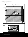
1
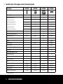
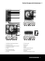
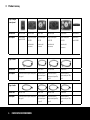
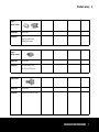
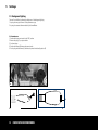
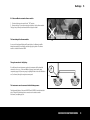
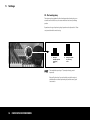
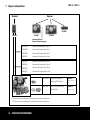
ALFA
10E 30E
20E 40E
instrument panel manual
Crafted with craftsman marine
Propulsion
Disclaimer
The specifications and descriptions in this manual have been entirely correct at the
moment of going to press. However, Craftsman Marine is always in pursuit of continuous improvement of its products and reserves the right to modify product specifications and instruction manuals at any given moment, without prior notice.
Safety
This page will provide you with a survey of all warning pictograms, used throughout
this manual. Notes referring to safety issues show this symbol:
DANGER
ATTENTION
Please adhere strictly to the recommendations in this chapter and instruct anybody
else, who may be operating or servicing the engine, to do likewise. these are the
safety recommendations:
• When the engine is in operation: do not touch any of the moving parts.
• When the engine is in operation several components will become very hot. Never
touch these parts and avoid the use of flammable products in the vicinity of the
engine.
• In the case of adjustment or inspection of parts of the engine and when filling in
lubrication oil or cooling liquid, the engine must be stopped and cooled down.
• Never open the cap of the expansion tank of the cooling liquid when the engine in
not entirely cooled down.
• All maintenance jobs should be executed by qualified mechanics, using properly
fitting tools.
If at all possible, only entrust these jobs to an authorized Craftsman Marine dealer.
Pay attention to the symbols and read the instructions in the
text.
Attention
(especially with a view to a safety risk for man or material)
2
Crafted with CRAFTSMAN MARINE
Table of contents
Table of contents
Disclaimer
2
Safety
2
Specifications of the engine control/
instrument panels
Monitoring lights
Scope of supply includes as well
4
2
Functions of the engine control/instrument
panel
5
3
Product survey
6
4
Installation
8
5
Settings
I – Calibration of the revolution counter
11
11
A. Fine-tuning (direct setting)
B. Adjust (adjustment via menu)
C. Pulse- (adjustment via menu)
11
11
11
II – Background lightning
12
A. Potentiometer
B. Craftsman Marine automatic dimmer module
12
13
III – Pre-heating relay
14
1
6
Operation
Starting the engine
Stopping the engine
15
15
15
7
Engine configurations
CM2.12 / CM2.16
CM3.27
CM4.33 / CM4.42
16
16
17
18
8
Alternative possibilities
Replacement of standard control/instrument
panel
Replace engine control/instrument panel of a
CM4.33 or CM4.42 engine
Extension of the ALFA20E panel with a
temperature gauge
20
20
Electrical wiring diagrams
24
4
4
9
10 Drilling pattern / principal dimensions
22
23
30
Crafted with CRAFTSMAN MARINE
3
1 Specifications of the engine control/instrument panels
Description
ALFA10E
ALFA20E
ALFA30E
ALFA40E
- high exhaust temperature
•
•
•
•
- low oil pressure in engine
•
•
•
•
- high cooling liquid temperature
•
•
•
•
- charging current of the battery
•
•
•
•
- pre-heating of the engine
•
•
•
•
- low oil pressure in the gearbox
-
optional
optional
optional
Acoustic alarm (buzzer)
•
•
•
•
Monitoring lights
Starter switch (pre-heating by hand)
•
•
•
•
optional
optional
optional
optional
Revolution counter/ Hour counter
-
•
•
optional
Voltmeter
-
•
•
optional
Temperature gauge
-
optional *1
•
optional
Oil pressure gauge
-
-
•
optional
Automatic dimmer (max. 20W)
-
optional
optional
optional
12 V
12 V
12 V
12 V
- Gasket under fitting edge
•
•
•
•
- 4 fixing screws
•
•
•
- Cover for starter switch
•
•
•
•
- 3 keys
•
•
•
•
Panel dimensions [mm]
100 x 166
198 x 166
260 x 166
150 x 50
Build-in dimensions [mm]
76 x 138
175 x143
237 x 143
102 x 34
114
114
114
114
75 x 142
174 x 142
236 x 142
124
Automatic pre-heating
Supply voltage
Scope of supply includes as well:
Build-in depth [mm]
Distance of fastening holes [mm]
*1 in lieu of the volt meter
4
Crafted with CRAFTSMAN MARINE
Functions of the engine control/instrument panel 2
15
16
5
3
4
1
2
12
10
11
8
8
16
15
12
13
1
2
3
6
4
5
7
10
11
8
14
9
16
1
1.
2.
3.
4.
5.
6.
7.
8.
2
3
6
4
5
7
Alarm high exhaust temperature (raw water cooling circuit)
Alarm low oil pressure in engine
Alarm high temperature of cooling liquid (internal cooling circuit)
Alarm charging current of the battery
Pre-heating
Sensor for automatic dimmer of lighting
Alarm low oil pressure in gearbox (optional)
Starter switch
1
2
3
6
4
5
7
9. Cover for starter switch
10. Revolution counter
11. Hour counter
12. Voltmeter
13. Temperature gauge (internal cooling circuit)
14. Oil pressure gauge of the engine
15. Fixation holes
16. Gasket (for use below fitting edges at rear of panel)
Crafted with CRAFTSMAN MARINE
5
3 Product survey
Type of engine
control panel
Article code
AB.010.20000
AB.020.20000
Description
Engine control
panel ALFA10E
AB.020.20001
AB.030.20000
AB.030.20001
AB.040.20000
Engine control panel Engine control panel
ALFA 20E
ALFA 20E
Engine control panel
ALFA 30E
Engine control panel
ALFA 30E
Engine control
panel ALFA40E
with black dial
instruments
with white dial
instruments
with black dial
instruments
with white dial
instruments
AB.050.20004
AB.050.20006
AB.050.20010
Type of cable
Article code
AB.050.20002
Description
Connection cable for engine control panel Connection cable for
engine control panel
2m, type A
4m, type A
Connection cable for
engine control panel 6m,
type A
Connection cable for
engine control panel 10m,
type A
Article code
AB.050.21002
AB.050.21006
AB.050.21010
Description
Connection cable for engine control panel Connection cable for
2m, type B
engine control panel
4m, type B
Connection cable for
engine control panel 6m,
type B
Connection cable for
engine control panel 10m,
type B
Type of cable
6
Crafted with CRAFTSMAN MARINE
AB.050.21004
Product survey 3
Type of
switch / sensor
Article code
DB.020.20001
Description
KIT:
Oil pressure switch/ sensor,
0.49bar/0-8bar, adapter
Type of
switch / sensor
Article code
DB.020.20002
Description
Temperature switch/sensor,
105 °Celsius /40-120 °Celsius
Type of sensor
Article code
DB.020.20003
Description
Temperature sensor 40-120° Celsius
Crafted with CRAFTSMAN MARINE
7
4 Installation
Engine control/ instrument panel
1. Determine the correct position for the panel, in a
place where the skipper has a clear survey of the
panel and where no heavy vibrations can occur.
2. If the control panel is fitted outside , the cover for
the starter switch must be fitted too, so as to avoid
dirt and (sea) water entering into the switch. Only
the top side of the panel is watertight.
3. Cut out a hole into the steering stand with the aid
of the supplied drilling pattern.
4. Position the gasket at the bottom of the panel; a
recess to receive the gasket is provided all around
in the edge.
5. Connect the extension cables type A and B with the
engine control/instrument panel.
6. Fit the panel with the aid of the 4 screws and
plastic washers, supplied.
Cover (see pictures below)
1. Remove the plastic ring
2. Remove the nut
3 Position the cover
4. Fit the nut and the cover
1.
2.
3.
4.
Engine control/instrument panel ALFA40E
Fix the position of the panel at the rear with the aid of
the bracket supplied.
8
Crafted with CRAFTSMAN MARINE
Installation 4
Engine control/instrument panel type ALFA40E
The engine control panel type ALFA40E features 3 plugs which must be connected
as follows: (see picture 5)
5.
Following instruments or switches can be connected onto the control panel type ALFA40E:
Red
Black
Red
Black
Black
Violet
Oil pressure meter
Violet
Blue
Connections of the oil pressure gauge
Red
Volt meter
Black
Connections of the volt meter
Black
Black
Connections of starter switch
Violet
Temperature gauge
Connections of the temperature gauge
Brown
Connections of the revolution counter
Crafted with CRAFTSMAN MARINE
9
Notes
10
Crafted with CRAFTSMAN MARINE
Settings 5
I – Calibration of the revolution counter
In order to achieve the correct indication of the revolution counter, this instrument
must be calibrated with the engine. Please take following steps:
1. This work can best be done by 2 persons.
2. Measure the number of engine revolutions with a manual revolution counter at the crank shaft.
3. Set the engine at 2000 revolutions.
4. As soon as the manual revolution counter indicates 2.000 revs, adjust the
revolution counter in the instrument panel accordingly.
The revolution counter can be calibrated by 3 methods (A, B or C ). Select your most
convenient method:
A. Fine-tuning (direct setting)
This method allows for an adjustment of -20% to +20% as opposed to the factory
setting.
When the engine is in operation:
1. Keep the button at the back of the revolution counter depressed, in order to
increase the indication figure.
2. If the button is released and kept depressed thereafter, the indication figure of the
revolution counter will be decreased.
3. Adjust the number of revolutions of the revolution counter in the panel by the same
value as indicated by the manual revolution counter.
B. Adjust (adjustment via menu)
This method allows for adjustment if the indication is within the bracket between
30% en100% (1200-4000 rpm)
When the engine is in operation:
1. Keep the button at the back of the revolution counter depressed and position the
starter switch in the “ON” position.
2. The display will now show the text PULSE or ADJUST.
3. Push the button until the word ADJUST will show.
4. Release the push button.
5. Now keep the button at the back depressed in order to raise the indicated number
of revolutions.
6. If the button is released and kept depressed thereafter, the indication figure of the
revolution counter will be decreased . 7. Adjust the number of revolutions of the revolution counter in the panel by the same
value as indicated by the manual revolution counter.
8. Turn the starter switch to the “OFF” position and thereafter to the “ON” position.
C. Pulse - (adjustment via menu)
This method allows for adjustment if it is known how many pulses per revolution are
generated by the alternator or the sensor. This method does NOT involve the starting
up of the engine.
Action to take:
1. Keep the button at the back of the revolution counter depressed and position the
starter switch in the “ON” position.
2. The display will now show the text PULSE or ADJUST.
3. Push the button until the word PULSE will show.
4. Release the push button.
5. The display will now show the number of pulses/revolutions as per the factory
setting. Example: 1 2 3 . 4 5
6. Figure 5 will now begin to blink (maximum 3 times). Press the button in order to
increase or decrease the figure. At first the values will be increased, thereafter
decreased.
7. If you do no react after three times blinking, following figures will start to blink
successively: 4, 3,2 and 1.
8. Adjust with the aid of these figures the required number of pulses/revolutions.
9. After completion of figure 1 , the menu will close down automatically. This can
also be achieved by cutting off the voltage supply.
Crafted with CRAFTSMAN MARINE
11
5 Settings
II – Background lighting
There are 2 possibilities for dimming the brightness of the background lighting:
1. by using an own type of dimmer of the potentiometer type
2. by using the automatic dimmer module by Craftsman Marine.
A. Potentiometer:
1. Position the battery main switch in the ‘OFF’ position
2. Remove the plug (A) ; see picture below
3. Cut the wire loop
4. Position the dimmer (B) between the two wire ends
5. Put the plug with the dimmer (A) back into the printed circuit board (position J6)
A.
B.
A.
3.
12
Crafted with CRAFTSMAN MARINE
4.
Settings 5
B. Craftsman Marine automatic dimmer module:
1. Position the battery main switch in the “OFF” position
2. Remove the plug A (see adjacent picture) and replace it by the dimmer module.
The plug that you have just now removed will no longer be needed.
The functioning of the dimmer module:
A.
As soon as the background lighting will be switched on, the illumination will be
dimmed automatically, in accordance with the night getting darker. The dimmer
module is suitable for maximum 20W.
Through-connection of the lighting:
If, in addition to the main instrument panel, other instruments will be placed and
connected, such as, e.g., a Craftsman Marine fuel gauge, (waste) water gauge,
temperature gauge or oil pressure gauge, the lighting thereof can also be switched on
or off, or dimmed, through the engine instrument panel.
The instruments must be connected in the following manner:
Red
Black
Lighting
Volt meter
Other instrument
The background lighting of the panels ALFA20E and ALFA30E is furnished with dual
plugs. Through this connecting point a connection can be made to another
instrument; see adjoining picture.
Crafted with CRAFTSMAN MARINE
13
5 Settings
III - Pre-heating relay
The engine may be equipped with either a hand-operated pre-heating relay, or an
automatic one. In the latter case, the starter switch does not show a pre-heating
position.
Dependent on the type of pre-heating relay, the panel must be adjusted to it. Please
see picture below for the switch setting.
I
Setting for
manually operated
pre-heating
asasa
II
Setting for automatic pre-heating
asasa
The standard factory setting is ‘I’ (manual pre-heating, switch
depressed).
Only modify the setting if you are absolutely sure that the engine is
provided with an automatic pre-heating relay and the correct type of
starter switch.
14
Crafted with CRAFTSMAN MARINE
Operation 6
Operation of the control panel
Starting the engine:
1. Before staring up the engine, always verify the following:
------
level of lubrication oil
level of cooling liquid (internal cooling circuit)
whether the seacock for the entry of raw cooling water is in the open position
whether the main battery switch is switched on
whether the gearbox is in the neutral position
2. From the ‘OFF’ position, turn the starter key one position to the right,
to the ‘ON’ position.
The monitoring lights for oil pressure and current charging will light up and the buzzer
sounds.
3. Pre-heating:
Pre-heating, only of required; please see your engine instruction manual.
Pre-heating by hand:
-- Now turn the switch to the pre-heating position and keep it there. The
pre-heating monitoring light will light up. The time involved in keeping the
switch in the pre-heating position is dependent on the type of engine, Please
see the relevant engine instruction manual
4. Thereafter turn the switch further to the right, to the ‘START’
position.
Release the key as soon as the engine springs to life; the key will return automatically to the ‘on’ position, where it will remain parked as long as the engine is in
operation.
Stop the starting procedure if the engine does not respond within a
period of 10 seconds. Release the key and wait till the starter motor has
come to a complete stand-still before giving it another try. Never have
the starter motor working for more than 30 seconds continuously, so as
to avoid damage by overheating.
5. Verify that the monitoring lights of oil pressure and charging
current are extinguished and make sure that the raw cooling
water is streaming out of the exhaust. If this is not the case,
then turn off the engine IMMEDIATELY.
Never turn the main battery switch to the ‘off ‘ position when the engine
is running. Never turn the starter switch to the ‘start’ position when the
engine is running, so as to avoid serious damage to the starter motor.
Automatic pre-heating (optional):
-- Place the starter switch in the ON position. The pre-heating indicator on the
instrument panel will light up.
-- Wait with the starting procedure until this monitoring light is extinguished.
Stopping the engine:
Have the engine running at idling speed for a few moments. Switch the gearbox into
its neutral position and turn the key to the far left, to the ‘STOP’ position. Then turn
the key one position to the right, to the ‘OFF’ position, when the engine has stopped.
Crafted with CRAFTSMAN MARINE
15
7 Engine configurations
CM2.12 / CM2.16
Standard:
Optional:
ALFA40E
ALFA20E
ALFA10E
ALFA30E
Standard: Volt meter
Optional: Temperature gauge
AB.050.20002
Connection cable engine panel 2m, type A
AB.050.20004
Connection cable engine panel 4m, type A
AB.050.20006
Connection cable engine panel 6m, type A
AB.050.20010
Connection cable engine panel 10m, type A
AB.050.21002
Connection cable engine panel 2m, type B
AB.050.21004
Connection cable engine panel 4m, type B
AB.050.21006
Connection cable engine panel 6m, type B
AB.050.21010
Connection cable engine panel 10m, type B
DB.020.20002
DB.020.20001
*1: The temperature switch in the engine must be replaced by the temperature switch/sensor
*2: The oil pressure switch in the engine must be replaced by the oil pressure switch/sensor
16
Crafted with CRAFTSMAN MARINE
Temperature switch/sensor
105 degrees/40-120 degrees
KIT Oil pressure switch/sensor,
0.49 bar/0-8 bar
Optional *1:
ALFA20E + temperature
gauge
Optional *2:
ALFA30E + ALFA40E
Engine configurations 7
CM3.27
Standard:
Optional:
ALFA40E
ALFA20E
ALFA30E
Standard: Volt meter
Optional: Temperature gauge
AB.050.20002
Connection cable engine panel 2m, type A
AB.050.20004
Connection cable engine panel 4m, type A
AB.050.20006
Connection cable engine panel 6m, type A
AB.050.20010
Connection cable engine panel 10m, type A
AB.050.21002
Connection cable engine panel 2m, type B
AB.050.21004
Connection cable engine panel 4m, type B
AB.050.21006
Connection cable engine panel 6m, type B
AB.050.21010
Connection cable engine panel 10m, type B
DB.020.20002
DB.020.20001
Temperature switch/sensor
105 degrees/40-120 degrees
Optional *1:
KIT Oil pressure switch/sensor,
0.49 bar/0-8 bar
Optional *2:
ALFA20E + temperature
gauge
ALFA30E + ALFA40E
*1: The temperature switch in the engine must be replaced by the temperature switch/sensor
*2: The oil pressure switch in the engine must be replaced by the oil pressure switch/sensor
Crafted with CRAFTSMAN MARINE
17
7 Engine configurations
CM4.33 / CM4.42
Standard:
Optional:
ALFA40E
ALFA30E
ALFA20E
Standard: Volt meter
Optional: Temperature gauge
AB.050.20002
Connection cable engine panel 2m, type A
AB.050.20004
Connection cable engine panel 4m, type A
AB.050.20006
Connection cable engine panel 6m, type A
AB.050.20010
Connection cable engine panel 10m, type A
AB.050.21002
Connection cable engine panel 2m, type B
AB.050.21004
Connection cable engine panel 4m, type B
AB.050.21006
Connection cable engine panel 6m, type B
AB.050.21010
Connection cable engine panel 10m, type B
DB.020.20003
DB.020.20001
*1: The temperature switch in the engine must be replaced by the temperature switch/sensor
*2: The oil pressure switch in the engine must be replaced by the oil pressure switch/sensor
18
Crafted with CRAFTSMAN MARINE
Temperature sensor
40-120 degrees
Optional *1:
KIT Oil pressure switch/sensor,
0.49 bar/0-8 bar
Optional *2:
ALFA20E +temperature
gauge
ALFA30E + ALFA40E
Notes
Crafted with CRAFTSMAN MARINE
19
8 Alternative possibilities
Survey of extension possibilities of the control panels and the sensors required:
Engine type
Standard supply
ALFA20E with volt meter
ALFA20E with temperature gauge
CM2.12, CM2.16
ALFA10E
No extra sensors required
Sensor:
DB020.20002 Sensor:
DB020.20002
DB020.20001
CM3.27
ALFA20E
(with volt meter)
-
Sensor:
DB020.20002 Sensor:
DB020.20002
DB020.20001
CM4.33, CM4.42
ALFA20E
(with volt meter)
-
Sensor:
DB020.20003 Sensor:
DB020.20003
DB020.20001
ALFA30E / ALFA40E
Replacement of standard control/instrument panel
(with CM2.12, CM2.16 & CM3.27 engines)
I a - CM2.12, CM2.16 en CM3.27 with an ALFA20E panel + temperature
gauge
Following must be done to connect an ALFA20E panel to the engine models CM2.12,
CM2.16 or CM3.27:
1. Remove the temperature switch (see the adjoining picture)
2. Fit instead the temperature switch/sensor type DB.020.20002
3. The wiring features 2 plugs: one for the temperature switch and the other one for
the temperature sensor. Connect these plugs as indicated with the adjoining picture.
4. Remove the ALFA10E panel.
5. Install instead the ALFA20E panel and fit the temperature gauge.
20 Crafted with CRAFTSMAN MARINE
Temperature
sensor
Temperature sensor
Temperature
switch
Temperature switch
N.B.: the engine
models CM2.12,
CM2.16 / CM3.27
have a switch
instead of the plug!
Alternative possibilities 8
I b - CM2.12, CM2.16 and CM3.27 with an ALFA30E or ALFA40E control/instrument panel
Following must be done to connect an ALFA20E panel to the engine models CM2.12,
CM2.16 or CM3.27:
1. Follow the steps 1 to 4, described on the previous page
2. Remove the oil pressure switch (see the adjoining picture).
3. Fit instead the adapter and the oil pressure switch / sensor type DB.020.20001
4. The wiring features 2 plugs: one fort the oil pressure switch and the other one for
the oil pressure sensor. Connect these plugs as indicated in the picture below.
5. Remove the ALFA10E or ALFA20E panel
6. Fit instead the ALFA30E or ALFA40E panel
Oil pressure
Oil pressure
switch
switch
Oil pressure
Oil pressure sensor
sensor
Crafted with CRAFTSMAN MARINE
21
8 Alternative possibilities
Replace engine control/instrument panel of a CM4.33 or CM4.42 engine
II a - CM4.33 / CM4.42 with an ALFA20E panel + temperature gauge
Following must be done to connect an ALFA20E panel to the engine models CM4.33
and CM4.42:
1. Remove the plug from the thermostat housing (see adjoining picture)
2. Fit instead the temperature sensor type DB.020.20003
3. The wiring features two plugs: one for the temperature switch (already fitted) and
the other one for the temperature sensor. Connect this plug to the temperature
sensor.
4. Fit the temperature gauge, as per description on page 23.
II b - CM4.33 / CM4.42 with an ALFA30E orALFA40E control/instrument panel
Following must be done to connect an ALFA30E or ALFA40E panel to the engine
models CM4.33 and CM4.42:
1. Follow the steps 1 to 3, described here above
2. Remove the oil pressure switch (see adjoining picture)
3. Fit instead the adapter and the oil pressure switch/sensor type DB.020.20001
4. Remove the ALFA20E panel
5. Fit instead the ALFA30E or ALFA40E panel
22 Crafted with CRAFTSMAN MARINE
Alternative possibilities 8
Extension of the ALFA20E panel with a temperature gauge
Following must be done to replace the voltmeter in the ALFA20E panel by a
temperature gauge. If so required, the temperature gauge may also be positioned
next to the panel.
1. Remove the connecting plugs from the voltmeter.
2. Remove the voltmeter by loosening the bracket (see picture A.)
3. Remove the finishing ring from the temperature meter, by turning it anti-clockwise
(see picture B). Make sure that the glass will stay in place.
4. Fit the temperature gauge and fix it with the bracket
5. Fit the plug of the background lighting.
6. Fit the plug of the temperature gauge (brown wire, to the rear of the wiring), see
picture C.
A.
B.
Red
Red
Black
Black
Black
Black
Violet
Voilet
Temperature
gauge
Temperature gauge
Brown
Brown
C.
Crafted with CRAFTSMAN MARINE 23
9 Electrical wiring diagrams
1.
Panel Panel
side side
2.
4.
5.
3.
8.
7.
6.
Pre-heating
(Glow Plugs)
Engine side
Engine
side
ALFA10E
WARNING LAMP PCB
9. 10.
11. 12. 13.
14.
15.
24 Crafted with CRAFTSMAN MARINE
18.
19. 20. 21.
Electrical wiring diagrams 9
Explanation wiring diagram
A1
Red
4
Plug engine control panel type B
A2
Violet
5
Plug engine extension cable type B
A3
Yellow
A4
Orange
6
Battery
A5
White
7
Battery main switch
A6
Black
8
Automatic fuse
9
Starter motor
B1
Green
10
Starter relay
B2
Brown
B3
Grey
11
Pre-heating plug
B4
Yellow/green
12
Pre-heating relay
B5
Blue
13
Fuel lift pump (ETR = energized to run)
B6
Pink
14
Stop solenoid (ETS = energized to stop)
B7
Blue
15
Alternator
B8
Brown
B9
Yellow/green
16
Sensor cooling liquid temperature *1
B10
Pink
17
Sensor oil pressure engine *1 *2
B11
Not connected
18
Switch cooling liquid temperature
B12
Not connected
19
Switch oil pressure engine
J1
Plug for starter switch
20
Switch exhaust temperature
J2
Plug for alarms
21
Switch oil pressure in gearbox *1
J3
Plug for monitoring instruments *1
22
Voltmeter *1
J5
Plug for external buzzer
23
Revolution counter/hour counter *1
J6
Plug for dimmer module *1
24
Oil pressure gauge *1 *2
25
Temperature gauge *1 *3
1
Starter switch
2
Plug engine control panel type A
3
Plug engine extension cable type A
*1: not for ALFA10E
*2: not for ALFA 20E
*3: optional for ALFA20E
Crafted with CRAFTSMAN MARINE 25
9 Electrical wiring diagrams
1.
22. 23.
25.
Panel Panel
side side
2.
4.
5.
3.
Engine side
Engine
side
ALFA20E
WARNING LAMP PCB
8.
7.
6.
9.
10. 11. 12. 13. 14.
15.
26 Crafted with CRAFTSMAN MARINE
16.
18.
19. 20. 21.
Electrical wiring diagrams 9
Explanation wiring diagram
A1
Red
4
Plug engine control panel type B
A2
Violet
5
Plug engine extension cable type B
A3
Yellow
A4
Orange
6
Battery
A5
White
7
Battery main switch
A6
Black
8
Automatic fuse
9
Starter motor
B1
Green
10
Starter relay
B2
Brown
B3
Grey
11
Pre-heating plug
B4
Yellow/green
12
Pre-heating relay
B5
Blue
13
Fuel lift pump (ETR = energized to run)
B6
Pink
14
Stop solenoid (ETS = energized to stop)
B7
Blue
15
Alternator
B8
Brown
B9
Yellow/green
16
Sensor cooling liquid temperature *1
B10
Pink
17
Sensor oil pressure engine *1 *2
B11
Not connected
18
Switch cooling liquid temperature
B12
Not connected
19
Switch oil pressure engine
J1
Plug for starter switch
20
Switch exhaust temperature
J2
Plug for alarms
21
Switch oil pressure in gearbox *1
J3
Plug for monitoring instruments *1
22
Voltmeter *1
J5
Plug for external buzzer
23
Revolution counter/hour counter *1
J6
Plug for dimmer module *1
24
Oil pressure gauge *1 *2
25
Temperature gauge *1 *3
1
Starter switch
2
Plug engine control panel type A
3
Plug engine extension cable type A
*1: not for ALFA10E
*2: not for ALFA 20E
*3: optional for ALFA20E
Crafted with CRAFTSMAN MARINE 27
9 Electrical wiring diagrams
1.
22. 23. 24. 25.
Panel side
Panel side
2.
4.
5.
3.
8.
7.
6.
Pre-heating
(Glow Plugs)
Engine side
Engine
side
ALFA30E / ALFA40E
WARNING LAMP PCB
9. 10. 11. 12. 13.
14.
15.
28 Crafted with CRAFTSMAN MARINE
16. 17. 18.
19. 20. 21.
Electrical wiring diagrams 9
Explanation wiring diagram
A1
Red
4
Plug engine control panel type B
A2
Violet
5
Plug engine extension cable type B
A3
Yellow
A4
Orange
6
Battery
A5
White
7
Battery main switch
A6
Black
8
Automatic fuse
9
Starter motor
B1
Green
10
Starter relay
B2
Brown
B3
Grey
11
Pre-heating plug
B4
Yellow/green
12
Pre-heating relay
B5
Blue
13
Fuel lift pump (ETR = energized to run)
B6
Pink
14
Stop solenoid (ETS = energized to stop)
B7
Blue
15
Alternator
B8
Brown
B9
Yellow/green
16
Sensor cooling liquid temperature *1
B10
Pink
17
Sensor oil pressure engine *1 *2
B11
Not connected
18
Switch cooling liquid temperature
B12
Not connected
19
Switch oil pressure engine
J1
Plug for starter switch
20
Switch exhaust temperature
J2
Plug for alarms
21
Switch oil pressure in gearbox *1
J3
Plug for monitoring instruments *1
22
Voltmeter *1
J5
Plug for external buzzer
23
Revolution counter/hour counter *1
J6
Plug for dimmer module *1
24
Oil pressure gauge *1 *2
25
Temperature gauge *1 *3
1
Starter switch
2
Plug engine control panel type A
3
Plug engine extension cable type A
*1: not for ALFA10E
*2: not for ALFA 20E
*3: optional for ALFA20E
Crafted with CRAFTSMAN MARINE 29
10 Drilling pattern / principal dimensions
V erify all dimensions closely, prior to cutting!
MAKE USE OF SEPARATE A4 SHEETS TO MAKE THE PATTERN!
ALFA10E
12
not
ample
x
e
2.0 (4x)
30
Crafted with CRAFTSMAN MARINE
to
scale
DrillDrill
pattern
pattern
scale
in mm
scale
in mm
75
77
100
12
166
142
139
Drilling pattern / principal dimensions 10
Verify all dimensions closely, prior to cutting!
MAKE USE OF SEPARATE A4 SHEETS TO MAKE THE PATTERN!
ALFA20E
12
198
176
174
12
144
166
example
pattern
DrillDrill
pattern
scale
in mm
scale
in mm
142
not
to
scale
2.0 (4x)
Crafted with CRAFTSMAN MARINE
31
10 Drilling pattern / principal dimensions
Verify all dimensions closely, prior to cutting!
MAKE USE OF SEPARATE A4 SHEETS TO MAKE THE PATTERN!
260
238
236
12
ALFA30E
12
example
2.0 (4x)
150
124
103
not
example
32 Crafted with CRAFTSMAN MARINE
to
scale
ALFA40E panel
35
50
11 (2x)
ALFA40E
Drill pattern
1:1
Drillscale:
pattern
Check paper size
scale in mm
before cutting!
144
166
DrillDrill
pattern
pattern
scale
in mm
scale
in mm
142
not
to
scale
Notes
Crafted with CRAFTSMAN MARINE 33
Notes
34 Crafted with CRAFTSMAN MARINE
Notes
Crafted with CRAFTSMAN MARINE 35
ZD-010-006.2.1.10.09
[email protected]
www.craftsmanmarine.com
Crafted with craftsman marine