1
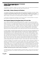
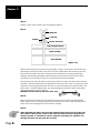
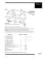
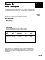
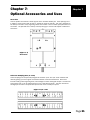
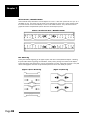
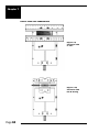
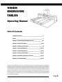
VISION
ENGRAVING
TABLES
Table of
Contents
Operating Manual
Table Of Contents
Liability Statement ________________________________________ 2
Safety ____________________________________________________ 3
Chapter 1: Unpacking and Taking Inventory _______________ 5-8
Chapter 2: Table Description ____________________________ 9-14
Chapter 3: Setting Up The Table ___________________________ 15
Chapter 4: Table Adjustments __________________________ 17-20
Chapter 5: Table Maintenance __________________________ 21-24
Chapter 6: Earlier Table Models ________________________ 25-30
Chapter 7: Optional Accessories and Uses ______________ 31-39
Chapter 8: Troubleshooting ____________________________ 41-44
This manual is designed to provide you with information about your Vision Computerized Engraving
and Routing Systems table, beginning with unpacking the table and continuing through installation
and lifetime table maintenance. This manual does not attempt to teach you how to engrave, how to
use a computer, or how to use your engraving software. Some previous knowledge of engraving terms
and the engraving process is assumed. For information on your individual computer system, see your
computer’s user manual or contact your computer distributor. For information on the engraving software
you use to drive your engraving system, see the manual for the individual software package supplied
by the software developer.
Page 1
Copyright 1998 Vision Computerized Engraving & Routing Systems
(A Division of W
estern Engravers Supply
Western
Supply,, Inc.)
All Rights Reserved
This publication is protected by copyright, and all rights are reserved. No part of this manual may be reproduced or
transmitted by any means or in any form, without prior written consent from Vision.
Limits of Liability / Disclaimer of W
ar
ranty for this T
able Manual:
War
arranty
Table
The information contained within this manual has been carefully checked and is believed to be accurate, however,
Vision makes no representations or warranties for this manual, and assumes no responsibility for inaccuracies, errors,
or omissions that may be contained within this manual. In no event shall Vision be liable for any loss of profit
including (but not limited to) direct, indirect, special, incidental, consequential, or other damages resulting from any
defect or omission in this manual, even if previously advised of the possibility of such damages.
In the interest of continued product development, Vision reserves the right to make improvements to this manual
and the products it describes at any time, without notice or obligation.
Vision Computerized Engraving and Routing Systems W
ar
ranty FFor
or The Vision T
able:
War
arranty
Table:
Vision Computerized Engraving and Routing Systems warrants that for a period of one (1) year from the date of
delivery to the user of the Vision table, that the table will be free from defects in material and workmanship under
normal use and service. It is specifically understood that this warranty covers normal use only and shall be null and
void in the event that the Vision table is altered or modified by the user without authorization, or is subject to abuse,
neglect, or other misuse by the user. The spindle is covered by a ninety-day (90) warranty. Other equipment may
be purchased which is not included in this warranty, and may have a separate manufacturer’s warranty, which
applies. Other items considered “consumable”, are not covered and are excluded from any and all warranties.
Specifically these items include spindle motor brushes, spindle belts, lubricant, and cutters furnished with the table.
In the event a defect is discovered during the warranty period, the user shall contact Vision Computerized Engraving
and Routing Systems for instructions regarding resolution of the problem. Vision Computerized Engraving and
Routing Systems shall at its option, replace the Vision table or correct the defect or problem by repair at Vision’s
manufacturing facility or at one of its authorized field service offices. In the event of either replacement or repair,
Vision Computerized Engraving and Routing Systems shall be liable only for the cost of repairs, including parts and
labor. Any incidental costs, including the cost of shipment from the user’s location to the point of repair, and
subsequent return, shall be at the expense of the user. Vision Computerized Engraving and Routing Systems shall
have no further liability hereunder. Vision Computerized Engraving and Routing Systems shall have no obligation or
liability to repair or replace, during the warranty period, those items that form a part of the Vision table and are
considered expendable by design, including but not limited to, cutters, spindle motor brushes, and spindle belts.
The above and foregoing is the only warranty of any kind, either express or implied, including but not limited to any
warranties of merchantability and fitness for a particular purpose, made by Vision Computerized Engraving and
Routing Systems on the Vision table. Any warranties expressed by law are hereby expressly disclaimed. No oral or
written information, advice, or other communications given by Vision Computerized Engraving and Routing Systems,
its dealers, distributors, agents, or employees shall create a warranty or in any way increase the scope of this warranty. Neither Vision Computerized Engraving and Routing Systems nor anyone who has ever been involved in the
creation, production, or delivery of the Vision table shall be liable for any direct, indirect, consequential, or incidental damages (including but not limited to damages for loss of business profits, business interruption, loss of business
information, and the like) arising out of the use or inability to use this product.
Any software supplied by Vision Computerized Engraving and Routing Systems in conjunction with the purchase of
the Vision Engraving table, for use therewith, shall be governed by its own separate software license and warranty
agreement.
Page 2
Safety Precautions
ables
for Vision Engra
ving TTables
Engraving
Safety
!Keep hands clear of the spindle belt during operation.
!Keep hands clear of the bottom of the spindle during operation.
!Always stop the machine before making any adjustments.
!Keep clear of adjustment knobs located on the rear, left and right side of the table.
!Disconnect the table cable and spindle drive cable before servicing.
!Do not operate the system with covers removed.
!Wear safety glasses when cutting any materials that emit chips. Use of the optional vacuum
system will remove most chips
!Use extreme caution when inserting or removing cutters, as cutter surfaces are very sharp.
Page 3
Page 4
Chapter 1:
aking In
or
Unpacking and TTaking
Invvent
entor
oryy
Chapter 1
The table or engraving system may be shipped in more than one carton, depending on the
options, software, and accessories purchased. The table itself is contained in a wooden crate
and the controller, if purchased, will be in a foam-pack cardboard container. Examine the condition of all containers for external damage. In the event of apparent external damage, notify your
carrier upon receipt and call your sales representative or Vision immediately.
Note: The shipping containers are considered reusable and should be stored for use
in the event of service need or upgrade.
Step 1. (Figure 1.1)
Open the wooden shipping crate by removing the Phillips-type screws holding the top lid down.
The following items should be included:
Reusable
Container
a. The engraving table
b. An accessory kit
c. Optional accessories you may have purchased.
Check all the items in the crate to assure they are of the correct type. Should any of the contents
be missing, damaged, or of the incorrect type, please call your sales representative immediately.
Step 2.
When unpacking the crate, be sure to look for items packed in boxes secured to the inside of the
shipping crate. Remove all of these items before attempting to remove the table. This may
include a table stand if purchased.
Page 5
Chapter 1
Step 3.
Prepare a clean, level surface to put the engraving table on.
Step 4.
Wing Nut
7/16” Nut
Washer
Plastic Protector
Engraving Baseplate
Foam Packing
Crate Bottom
(Figure 1.2)
Remove the four wing nuts by hand or by using pliers. Using a 7/16" wrench, remove the nuts
and washers securing the table to the floor of the crate. Most tables are secured at four locations around the base of the table. This prevents the machine from moving around during
shipment and becoming damaged. Plastic tie straps may have been used to secure various
mechanisms on the machine. These do not need to be removed immediately.
After removing the nuts and washers securing the table to the crate, the table can be carefully
removed. It is recommended that two people lift the table out of the crate. Four persons may be
required to remove larger tables from the crate. Do not lift the table by the stepper motors, the
lead screws, or similarly aligned parts. This could damage the bearings, motors, lead screws,
and general alignment of the engraver.
CAUTION: Lift the table by the base plate only!
Step 5.
Remove the plastic tie straps that may have been used to secure the Z-assembly (Spindle
Block). Remove them by cutting through with a sharp knife or scissors. After removing the tie
straps, remove the shipping foam from under the carriage.
Step 6.
After unpacking the table, save the crate and any other boxes as well as the nuts
and washers. They can be reused in the event the table must be transported to
another location or returned for service. Improper packaging for shipment can
damage the table and may void the warranty.
Page 6
Chapter 1
Step 7.
1.or3.
4.
6.
1.or3.
6.
Assembling the
optional table stand.
Approximate time for
assembly is 10-20
minutes.
4.
6.
1.or2.
5.
5.
5.
8.
1.or2.
(Figure 1.3)
Table stand for Vision 2424 and 2448 models
6.
7.
A. Cross beam is only for the 24” x 48” table stand.
B. Swivel casters are inserted up into the frame, in the positions indicated.
The ring at the neck of the caster can be turned to tighten the caster in place, once inserted.
C. Four 4¼” bolts are used to connect the table to the roll-around frame.
Note: All connections are made with a socket hex screw and washer (supplied).
Do not fully tighten all screws until the engraving table is bolted to the cross members (#4’s);
then align the legs (#6’s) to corners of the engraving table. This helps the overall alignment.
Description
1.
2.
3.
4.
5.
6.
7.
8.
9.
10.
11.
12.
13.
14.
15.
frame 38" w/o holes
frame 62" w/ holes
frame 62" w/o holes
frame 19.5" w/ holes
frame 19.5" w/o holes
frame 25" w/o holes
locking swivel caster
mounting bracket (optional)
t-handle hex key
socket head cap screw (5/16-18 x 1 1/4”)
sae (AN 5/16”) flat washer
socket head cap screw (1/4-20 x 4 1/2”)
nylock
uss (1/4”) flat washer
Instruction Sheet
24x24 Qty
4
2
2
4
4
1
16
16
4
4
8
1
24x48 Qty
2 (used to bolt center cross beam)
2
2
3 (one extra for center cross beam)
4
4
1
16 !
16 !
4 "
4 "
8 "
1
!connects frames together "mounts table (not shown) to frame
Page 7
Chapter 1
(Figure 1.4)
Table stand for Vision1624
1.
4.
4.
2.
5.
5.
5.
4.
3.
5.
4.
A.
3.
A. Swivel casters are inserted up into the frame, in the positions indicated. The ring
at the neck of the caster can be turned to tighten the caster in place, once inserted.
B. Four 4¼” bolts are used to connect the table to the roll-around frame.
Note: All connections are made with a socket hex screw and washer (supplied).
Do not fully tighten all screws until frame is assembled; this helps keep alignment.
Description
1.
2.
3.
4.
5.
6.
7.
8.
9.
10.
11.
12.
13.
frame 29” w/ holes
frame 29” w/ holes (different spacing)
frame 29” w/o holes
frame 26” w/o holes
frame 26” w/ holes
locking swivel caster
t-handle hex key
socket head cap screw (5/16-18 x 1 1/4”)
sae flat washer (AN 5/16”)
socket head cap screw (1/4-20 x 4 1/2”)
nylock
uss (1/4”) lat washer
Instruction Sheet
16x24 Qty
1
1
2
4
4
4
1
16 !
16 !
4 "
4 "
8 "
1
!connects frames together "mounts table (not shown) to frame
Page 8
Chapter 2:
Table Description
Chapter 2
This chapter briefly describes the major components of the Vision table. Figure 2.1 and Figure
2.3 show pictures of two typical engraving tables. This chapter will help you identify the parts of
your Vision table discussed elsewhere in the manual.* Find the model number as referenced in
the description for each type of table design.
*Optional equipment such as accessory vises, clamps, fixtures or vacuum systems may have
been included with your system. For information regarding this equipment, see the individual
instructions for these options. For descriptions of controllers, computers, and software used in
your system, see the manuals from the manufacturers of these units.
TABLE SPECIFICATIONS:
Z-Axis Clearance
(definition: the distance between the bottom of the spindle and the work surface)
Vision Tables: Adjustable Clearance
Z-Axis Stroke
(definition: the travel distance of the Z-axis mechanism or spindle)
Vision Tables: 1 7/8 Inches (31.75 mm)
Table Resolution
(definition: the smallest controlled motion the table is capable of)
.0005 inch on all tables (when connected to a Vision Controller)
Engraving
Table
Engraving
Area
Overall
Dimensions
Table
Type
approx. packaged
L x W x H
VISION
VISION
VISION
VISION
VISION
1212
1224
1624
2424
2448
12”x12”
12”x24”
16”x24”
24”x24”
24”x48”
28”x33”x16”
40”x33”x16”
40”x33”x16”
42”x33”x16”
66”x33”x16”
Shipping
Weight
T-Slot
T-Slot
T-Slot
Flatbed
Flatbed
202lbs.
269lbs.
269lbs.
371lbs.
520lbs.
DEFINITION OF TERMS
A. Tables With Moveable T-Slot Engraving Beds (VISION 12x12, 12x24, and 16x24)
In this design, the T-slot table moves in the Y-axis direction while the gantry remains fixed. The
carriage moves from left to right in the X-axis. There are no particular design advantages or
disadvantages to this style of table. The main engineering criteria in the development of this
design was the need to minimize the overall table footprint while providing the maximum
engraving area.
Page 9
Chapter 2
(Figure 2.1) Series 3 full linear T-slot table format. Shown here is the top view of
the Series 3 Vision 1624. The Vision 1212 and the Vision 1224 have a similar design.
6. Carriage Assembly
8. Y-Axis Stepper Motor (underneath)
11. Engraving Motor
7. Breakout Box
5. Gantry Assembly
9. X-Axis Stepper
Motor
10. Material Guides
1. Table Base Plate
3. T-Slot Table
12. Quick-Lock Vise
4. Y-Axis Lead Screw
(under metal cover)
2. Y-Axis Linear Rails
(Figure 2.1a) Series 3 T-slot table format. Shown here is front angled view of the
Series 3 Vision 1624.
11. Engraving Motor
5. Gantry Assembly
6. Carriage Assembly
8. Y-Axis Stepper Motor
9. X-Axis Stepper
Motor
10. Material Guides
7. Breakout Box
4. Y-Axis Lead Screw
(under metal cover)
2. Y-Axis Linear Rails
1. Table Base Plate
3. T-Slot Table
1. Table Base Plate. This is the large flat plate upon which everything else is mounted. All
mechanical alignments are referenced to this plate, so the space upon which you place the
engraving table must be a reasonably level surface.
2. Y-Axis Linear Rails. Mounted on the table base plate are steel rails with sealed
bearings, which allow the motion of the T-slot table in the Y-axis direction.
Page 10
Chapter 2
3. T-Slot Table. Also referred to as the work surface, this aluminum bed supported by the
linear rails allows placement of the engraving material or special clamps and fixtures. The
slots in this table are shaped with an upside-down T, with the bottom of the T being a
single-line slot across the top of the table (see fig 2.1b). The slots are used to hold various
accessory holders, clamps, and jigs. (A selection of various T-slot accessories used with the
T-slot table appears in chapter 7.)
4. Y-Axis Lead Screw. This is a threaded rod located underneath the T-slot table.
Combined with the stepper motor, the lead screw is rotated and causes the T-slot table to
move along the rails in the Y-axis direction (as seen in figure 2.1c). There is also a second
lead screw called the X-axis lead screw. The X-axis lead screw is contained within the gantry,
and can be accessed by removing the black sheet metal gantry cover. The X-axis lead screw
is responsible for X-axis motion of the carriage assembly, moving it left and right across the
gantry.
5. Gantry Assembly. The gantry or “bridge” is a large, rectangular bar suspended across
the width of the table in the X-axis. The carriage assembly is supported and rides on the
gantry in the X-axis.
6. Carriage Assembly. The carriage assembly houses the engraving spindle, Z-Axis
mechanism and engraving motor. The carriage moves along the gantry assembly on a set of
sealed bearing. The carriage assembly holds the engraving spindle; it raises and lowers the
spindle during the engraving process using a lead screw and stepper motor.
7. Breakout Box. This electrical access is used to connect the table to the system
controller. The breakout box and connector may be located in different locations near the
rear of the table and is usually protected by a sheet metal cover (see fig 3.1).
8. Y-Axis Stepper Motor. Drives the T-Slot table in the Y-Axis.
9. X-Axis Stepper Motor. Drives the carriage in the X-Axis. Located under the protective
sheet metal cover.
10. Material Guides. Used as a back and side stop for accurately locating material and
clamps during set-up.
11. Engraving Motor. Drives the spindle for rotary engraving.
12. Quick-Lock Vise. A “cam” type locking device that allows quick change of parts for
engraving.
(Figure 2.1b) T-slot close up
(Figure 2.1c) T-slot table motion
Page 11
Chapter 2
(Figure 2.2) Close up of the
Series 3 Vision table carriage
Shown is 3/4 view, without
sheetmetal top cover
1. Engraving Motor
2. Z-Axis Stepper Motor
5. Z Lead Screw
4. Spindle Block
6. Engraving
Motor Belt
3. Spindle Assembly
1. Engraving Motor. The engraving motor or “spindle motor”, is the large black motor on
the top of the carriage assembly. The engraving motor drives a belt and pulley system,
which turns the engraving cutter during the engraving process.
2. Z-Axis Stepper Motor. The small motor under the carriage cover that provides the up
and down motion of the spindle during the engraving process.
3. Spindle Assembly. The spindle mounted in its block; includes a pulley, housing,
micrometer, retainer ring, nose cone and associated hardware. The spindle assembly moves
up and down along a linear bearing, which attaches to the face of the carriage assembly.
4. Spindle Block. Houses the spindle assembly. See Chapter 4 for information on how to
remove the spindle assembly from the spindle block.
5. Z-Leadscrew. Connects the Z-axis stepper motor with the Z-axis linear rails to raise and
lower the spindle during the engraving process.
6. Engraving Motor Belt. Drive belt connecting the engraving motor to the spindle pulley.
B. Tables With Moveable Gantrys (“Flatbeds”-Vision 24x24, 24x48)
The difference in design of the flatbed table versus the moving T-slot type is that the flatbed work
area does not move. In this design, the entire gantry travels the length of the X-axis and the
carriage moves in the Y-axis.
Page 12
Chapter 2
(Figure 2.3) Series 3 flatbed (moveable gantry) table format. Shown here is a top
view of the Series 3 Vision 2424.
10. Engraving Motor
5. Carriage Assembly
4. Gantry Assembly
7. Y-Axis
Stepper Motor
3. X-Axis
Lead Screw
2. X-Axis
Linear Rails
9. Material Guides
1. Table Base Plate
8. X-Axis
Stepper Motor
6. Breakout Box
(Figure 2.3a) Front angled view of the Series 3 Vision 2448
7. Y-Axis Stepper
Motor Knob
5. Carriage Assembly
9. Material Guides
4. Gantry Assembly
1. Table Base Plate
2. X-Axis Linear Rails
6. Breakout Box
1. Table Base Plate. This is the large flat plate upon which everything else is mounted. All
mechanical alignments are referenced to this plate, so the space upon which you place the
engraving table must be a reasonably level surface. (Always carry the table by the base plate
only.)
2. X-Axis Linear Rails. Mounted under the table base plate are steel rails with sealed
bearings, which allow the motion of the gantry in the X-axis direction.
Page 13
Chapter 2
3. X-Axis Lead Screw. This is a threaded rod located underneath the table base.
Combined with the stepper motor, the lead screw is rotated and causes the gantry to move
along the rails in the X-axis direction (see fig 2.3b). There is also a second lead screw called
in the X-axis lead screw. The Y-axis lead screw is contained within the gantry, and can be
accessed by removing the black sheet metal gantry cover. The Y-axis lead screw is
responsible for motion of the carriage assembly, moving it left and right across the gantry.
4. Gantry Assembly. The gantry or “bridge” is a large, rectangular bar suspended across
the width of the table. It travels down the table along the X-axis (see fig 2.3b).
(Figure 2.3b) Gantry movement along the X-axis
Y-Axis
5. Carriage Assembly. The carriage
assembly houses the engraving
spindle, the Z-axis mechanism and the
engraving motor. The carriage moves
along the gantry assembly on a set of
sealed bearings in the Y-axis (see fig
2.3b). The carriage assembly raises
and lowers the engraving spindle
during the engraving process using a
lead screw and stepper motor.
6. Breakout Box. This electrical
access is used to connect the table to
the system controller. The breakout
box and connector may be located in
different locations near the rear of the
table and is usually protected by a
sheet metal cover.
7. Y-Axis Stepper Motor. Drives the
carriage in the Y-Axis.
8. X-Axis Stepper Motor. Drives the
gantry in the X-Axis.
9. Material Guides. Used as a back
and side stop for accurately locating
material and clamps during set-up.
X-Axis
Page 14
10. Engraving Motor. Drives the
spindle for rotary engraving.
Chapter 3:
Se
tting U
p The TTable
able
Setting
Up
Chapter 3
Connection of Power, Cables, and Controllers
Additional boxes may have been shipped along with your table, depending on the system
ordered. These will typically include a control unit and associated cables. The proper connection
of these cables is essential. Check the appropriate user’s manuals for your controller before
attempting to connect them it to the table. After connection of the cables as directed by your
controller manual, power can be connected to the system. It is suggested that a surge protector
be used. (A surge protector--often called “power strip”--is included with the newest Vision Serial
Controllers; otherwise, one may be purchased inexpensively at any hardware store.) If your
system was purchased with a Vision Serial Controller, a surge protector may have been included.
This will allow powering all of the elements of the system at once.
Some models may have included a separate spindle motor speed controller. This unit is powered
separately in some configurations. See the next section for information on installing this unit.
(Figure 3.1) Breakout box with 25-pin connection to the Vision Serial Controller
Back view of the
Vision Serial Controller
Page 15
Chapter 3
Page 16
Chapter 4:
Table A
djustments
Adjustments
Chapter 4
Spindle Assembly Description
Our most recent tables (the “Series 3’s”) include our newest spindle design, which now
incorporates tension spring adjustment.
(Figure 4.2) The Series 3 Top and
Bottom-Loading Collet Spindle
Assembly
(Figure 4.1) The Series 3 TopLoading Spindle Assembly
15.
14.
1.
2.
9.
3.
4.
5.
12.
13.
6.
11.
7.
10.
1.
2.
3.
4.
5.
6.
7.
8.
8.
Pulley
Inner Spindle Housing (under sleeve)
Outer Spindle Sleeve
Pressure Spring Adjuster
Pressure Spring
Micrometer
Retainer Ring
Nose cone
9. Draw Bar
10. Cutter
11. Solid Collet (Optional)
12. Split Collet
13. Pointer
14. Cutter Knob
15. Cutter Knob Setscrew
Page 17
Chapter 4
Zeroing Cutters for Top-Loaded Spindles (see figure 4.1)
1. Turn the micrometer to zero. This provides a starting point and reference for setting the
depth accurately. It’s important to note that the micrometer should be threaded onto the
spindle housing sufficiently to prevent excessive play in the micrometer and nosecone. If
there are too few threads holding the micrometer in place it will move during the engraving
process. The best starting position is 3 or 4 complete revolutions from the top.
CAUTION: When you loosen the setscrew in this step, the cutter may easily fall out
of the spindle and can cause cutter tip damage. Use one hand to hold the cutter
before loosening.
2. With the appropriate cutter installed in the spindle, loosen the setscrew in the brass
cutter knob with a spline wrench (commonly referred to as the cutter wrench).
3. Gently place a piece of metal (brass preferred) against the nosecone so as to push the
cutter even with the bottom of the nosecone. Now the cutter should be flush with the
nosecone. Retighten the cutter knob setscrew. Your cutter is now zeroed. Rotating the
micrometer clockwise will adjust the depth of the cut. Each click of the micrometer =
.001”. A full revolution is .025”.
Zeroing Cutters for Top-and-Bottom-Loaded Collet Spindles (see figure 4.2)
The collet spindle can be used for either top loaded or bottom loaded cutters. To install a top
loaded cutter in the collet spindle, first set the micrometer to zero. Loosen the knurled draw bar
on the very top of the spindle slightly. Remove the cutter knob from the cutter, and slide the
cutter into the spindle. Place a piece of flat material against the bottom of the nosecone and
lower the cutter until it rests against the material. Tighten the draw
bar around the cutter, make sure it is tight. Then reattach the cutter
knob to the top of the cutter and screw it in counterclockwise until
secure. Be careful screwing the cutter knob in, as counterclockwise is
the direction to unscrew the draw bar (see fig 4.3). Never use pliers!
The cutter depth can be adjusted by turning the micrometer counter
clockwise. Note: If using 2" short cutters, install them from the
bottom. Use the draw bar on the very top of the spindle to tightly
secure the cutter.
A solid collet, if purchased, can be installed in place of the split collet
for burnishing. Install the collet in the bottom of the spindle and
tighten the draw bar firmly. The spindle now acts as a normal top
loaded spindle for ease of operation. The split collet can be
reinstalled when required.
(Figure 4.3) Tightening the cutter
knob in the draw bar.
Page 18
Chapter 4
Proximity Sensing Device
All Series 3 Vision Table Models come standard with a proximity-sensing device.
Explanation and procedure for operating a Vision engraving machine equipped with a proximitysensing device.
Advantage of this feature
The advantage of this device is that it eliminates the need to perform a surface setting before
zeroing the cutter.
Procedure
1. Make sure that the proximity switch is in the “On” position on the controller front panel.
Ensure that some travel is allowed to “float” the spindle on the pressure spring.
2. Zero the cutter in the spindle and dial in the desired depth on the nose cone micrometer.
3. Send the job down to the controller via the computer.
4. Press the “Start” button on the controller front panel to begin engraving.
IMPORTANT NOTES:
“Nose-riding” - WITH proximity sensor
Engraving with the proximity sensor can only be performed with a nose cone
attached.
“Non-nose-riding” - WITHOUT proximity sensor
When setting a depth in the computer engraving program, the proximity switch
should be in the “Off” position on the controller front panel. Also, make sure that
there is no “float” on the spindle by locking the pressure spring adjuster all the way
down. Locking is especially important when engraving into hard surfacesor
materials like brass and stainless steel.
Diamond Engraving
To install a diamond drag adapter, remove the retainer ring and nose cone from the bottom of
the spindle and replace with the diamond drag adapter. (See fig.4.4 on the next page) For
diamond drag cutting, the engraving motor is turned off and the cutter “drags” across the
material. This is accomplished with the motor on/off switch in the “off” position. Down pressure
against the material can be reduced or increased as necessary by adjusting the spring pressure
adjuster as described in the next section.
Page 19
Chapter 4
(Figure 4.4) Series 3 Spindle
Shown With Diamond Drag
Adapter
Pulley
Spindle Housing
Pressure Spring
Adjuster
Micrometer
Diamond Drag
Adapter
Page 20
Chapter 5:
Table Maint
enance
Maintenance
Chapter 5
Vision strives for the highest quality in their manufacturing process to provide you
with the most cost effective, reliable engraving machine in use today. Please
remember that proper maintenance and care is necessary to achieve maximum
product life expectancy.
The engraving environment generates small plastic and metal chips as well as other particles
during operation. As with any machinery, your engraving system should be kept as clean as
possible to minimize wear and tear, and to improve final quality of the engraved product.
REMOVING CHIPS
Plastic and metal chips, generated during the engraving process, should be removed from the
engraving surface periodically. A portable vacuum is suggested for chip removal, but applying
direct suction to the spindle area is not recommended.
Note that this cleaning can be minimized and greatly simplified through the use of the optional
vacuum chip removal system. The vacuum chip removal system removes chips and dust created
by engraving. This system can also extend the life of other components in the system, as
prompt removal of chips reduces contamination and overheating in the spindle area. The
vacuum chip removal system also keeps the nose cone from skipping over letters due to chips
on the engraving surface.
Cleaning The Nose Cone
(Figure 5.1) Vacuum nose with hose
The nose cone around the cutter may accumulate dust and chips that cannot be removed by
sucking them off or blowing on them with low pressure air. (CAUTION! High pressure air can
damage the spindle.) Two types of nose cones are available; one nose cone is designed to be
used with the vacuum system, the other is not. Cleaning methods depend on the type of nose
cone in use.
With a vacuum chip removal system (see fig 5.1), most of the chips will be removed during the
engraving process. If the suction nozzle becomes clogged, remove the hose connection to the
nose cone. Remove the cutter, then unscrew the vacuum nose cone. Using a vacuum or an air
hose, clean out the nose and the vacuum tube leading to the nose cone. Reinstall the nose cone
and the vacuum hose.
Without a vacuum chip removal system you should remove the cutter before attempting to clean
the nose cone. The nose cone retainer ring, the nose cone, and the micrometer collar should all
be removed and cleaned using a vacuum or blowing air. The three nose cone components should
be removed and cleaned at least every day, and as frequently as necessary. Failure to clean the
nose cone regularly will result in premature spindle failure.
Page 21
Chapter 5
Cleaning the Vacuum Filter (only with the vacuum chip removal option)
On systems with a vacuum chip removal system, frequent cleaning of the vacuum filter is
necessary for proper performance. When engraving with the vacuum filter system, the filter
should be checked and cleaned several times a day, depending on the amount of engraving
done. If the vacuum does not appear to be functioning efficiently, clean the filter more frequently as needed.
To clean the vacuum filter system, disconnect the vacuum hose from the canister. On the lid of
the canister, note the three wing nuts. Loosen these nuts enough to allow the attached bolts to
swing away from the lid, allowing removal of the lid. Do not loosen the nuts enough to remove
them completely. Remove the canister lid and inside you will find two filters. Carefully remove
the inner, paper filter. (The paper and cloth filters tend to stick together.) Empty the paper filter,
and shake it out completely, being careful not to damage it as the filters are reusable. After
shaking out the paper filter remove and empty the cloth filter in the same manner as the paper
filter. Do not wash either filter. Place the paper filter back inside the cloth filter, and place the
cloth filter back inside the vacuum canister.
REPAIRS, REPLACEMENTS, AND ADJUSTMENTS
How to replace a belt
A belt is used to drive the spindle engraving system. It runs between a drive pulley and the
spindle pulley (see Fig.2.2 in Chapter 2). If it needs replacement, remove the old belt by rolling it
to the top of the spindle pulley, and give it a slight stretching motion to snap it off the end. Once
loose, it can easily be removed from the machine. Now position the new belt around the drive
pulley, then stretch it to snap over the top of the pulley.
NOTE: Be sure to puchase the specified replacement belt from Western Engravers
Supply. Having the exact tightness is extremely important to the functionality of the
motor. NEVER STRETCH THE BELT!
Motor Brushes
Carbon
Motor Brush
Threaded
Brush Cap
(Figure 5.2) The engraving motor
and brushes
Shown from front and side view
Page 22
Chapter 5
The motor brushes on the engraving motor should be inspected regularly, and replaced when
worn. Two brush assemblies are included with the accessories package. (One for each side of
the motor.)
Inspect the brushes for possible replacement at least every six months. (see figure 5.2)
The engraving motor is the large, black motor on the top of the carriage assembly. Unplug the
speed controller to remove power to the motor. Perform the inspection one brush at a time to
simplify reinstallation. At the top of the motor are two round extensions looking similar to ears.
Using a flat-blade screwdriver, carefully remove the small threaded brush cap from the center of
one of the “ears”. If you screw it in the wrong direction, the cap will descend into the ear
instead of rise out. Remove the metal U-shaped bracket connected to the spring and carbon
brush. It will be found underneath the brush cap. Observe how you remove the brush, so that
reinstallation will be easier. Examine the brush for wear by comparing it to a new brush, or by
measuring the length of the carbon brush. If the carbon brush is less than a quarter of an inch
long, replace the entire assembly. Do not attempt to separate the carbon brush from the wire,
spring and bracket. Reinstall the old or new bracket/spring/brush assembly followed by the
plastic brush cap. Repeat the inspection procedure for the brush on the other side of the motor.
NOTE: If either brush needs to be replaced, replace both brushes as a set.
LUBRICATION
Lubricating the X-Axis, Y-Axis and Z-Axis lead screws
(ALL MODELS)
A light lubrication of the X and Y and Z lead screws should
be performed after every week of usage (see fig. 5.2). Use
silicone lubricant only. Spray a light coating along the lead
screw. (A nozzle extender attached to the aerosol spray
can will facilitate this procedure and may eliminate the
need to remove the metal covers)
(Fig 5.3) Carriage and
gantry covers are removed.
Z
X&Y
DO NOT use any lubricant other than silicone, as
it may become sticky and cause a buildup that
can cause mechanical failure.
What not to lubricate
Many of the bearings and assemblies in your engraving
machine are sealed and/or coated using special lowfriction methods and should not be lubricated.
DO NOT attempt to lubricate the spindle or the
spindle bearings. If you suspect lubrication problems, call your
dealer/representative for instructions, as further lubrication may harm the machine.
DO NOT lubricate the X or Y stepper motors.
Page 23
Chapter 5
Spindle Lubrication (for Series 3 Vision Tables only)
The spindle assembly in the Series 3 Vision Tables requires a
monthly lubrication of the housing (as shown in Fig.5.4).
Simply push the spindle up until there is a 1/3” gap between
the spindle block and the “lip” of the housing. Lubricate with
2 to 3 drops of 3 in 1 oil.
DO NOT OVER LUBRICATE! This wil cause
the spindle to stick.
Spindle Housing “Lip”
Spindle Block
(Figure 5.4)
MAINTENANCE SCHEDULE
Following is a suggested maintenance schedule. Remember that in conditions of prolonged use,
unusual environments, or unusual applications, maintenance items may need to be performed
more frequently than suggested in this schedule.
Page 24
Frequency
Maintenance Items
As needed
1. Vacuum and/or brush
2. Clean vacuum canister filters
Every Day
1. Remove chips form the spindle if
you do not have a vacuum chip
removal assembly.
Every Week
1. Lubricate steel X, Y lead screws
Every Month
1 . Lubricate the Z-Axis lead screw
2 . Lubricate the Spindle Housing
Every Six Months
1 . Check the brushes and replace if
necessary.
2. Lubricate the Z-Axis linear bearing
Chapter 6:
Earlier TTable
able Models
Chapter 6
Over the years, most of the changes to Western’s engraving tables has been in the carriage
assembly. Earlier upgrades to the Z-axis have evolved from the Series 1 V-wheel design to the
Series2 THK bearing design. The terms and descriptions for these earlier models are the same
as the current models--please refer to chapter 2.
(Figure 6.1) Close up of the
Series2 THK carriage
Shown is 3/4 view, without
sheetmetal top cover
Engraving Motor
Z-Axis Stepper Motor
Terminal Blocks
Spindle Assembly
Engraving Motor Belt
Spindle Block
For a description
of terms, refer to
chapter 2.
(Figure 6.2) Series2 T-slot table with THK carriage design. Shown below is an angled
front view of the Vision 1624. The Series2 Vision 1212 and Vision 1224 models had a
similar design.
Engraving Motor
Carriage Assembly
Gantry Assembly
Y-Axis Stepper Motor
X-Axis Stepper
Motor
Material Guides
Breakout Box
Y-Axis Lead Screw
(under metal cover)
Table Base Plate
Y-Axis Linear Rails
T-Slot Table
Page 25
Chapter 6
Chapter 6
(Figure 6.3) Series2 flatbed (moveable gantry) table with THK carriage design.
Shown here is a top view of the Vision 2424.
10. Engraving Motor
5. Carriage Assembly
4. Gantry Assembly
7. Y-Axis
Stepper Motor
2. X-Axis Linear Rails
3. X-Axis Lead Screw
9. Material Guides
1. Table Base Plate
8. X-Axis
Stepper Motor
6. Breakout Box
(Figure 6.3a) An angled front view of the Series2 Vision 2448.
5. Carriage Assembly
7. Y-Axis
Stepper Motor
9. Material Guides
4. Gantry Assembly
Chapter 6
1. Table Base Plate
2. X-Axis Linear Rails
Page 26
6. Breakout Box
Chapter 6
6
(Figure 6.4) Close up of the Series1 V-wheel carriage assembly and spindle block.
Engraving Motor
Z-Axis Knurled
Thumb Wheel
Engraving
Motor Belt
Spindle
Assembly
Spindle Block
Z-Lead Screw
V-Wheel
X-Axis Rail
(Figure 6.5) Series1 version T-Slot Table Model with V-wheel carriage design
Shown below is the Vision 1624 (Series1 Vision 1212 and 1224 were similar).
Carriage Assembly
Stepper Motors
Motor Speed
Controller Plug
Engraving Motor
Material
Guides
Y-Axis
Lead Screw
Gantry
(the X-Axis
Lead Screw
is under the
metal cover)
T-Slot Table
Quick Lock Vise
Base Plate
Page 27
Chapter 6
Chapter 6
(Figure 6.6) Series1 Flatbed Table Model with V-wheel carriage design
Series1 Vision 2448 model is shown. The Series1 Vision 2424 was similar.
Stepper
Motor
Gantry (inside is the Y-Axis
lead screw)
Material Guides
Lead Screw
X-Axis
Base Plate
Carriage
Assembly
Engraving
Motor
37-pin plug
Motor
Speed
Controller
Plug
Stepper Motor
Y-Axis
MAINTENANCE FOR EARLIER MODELS
Most maintenance procedures are similar to those for the current models. However, the
process for lubrication differs slightly with the earlier models.
LUBRICATION FOR SERIES1 AND SERIES2 VISION MODELS
Lubricating the Z-Axis Linear Bearings
The Z-axis linear bearing provides the support for the spindle block
assembly. It can be lubricated without removing the carriage cover.
For ease of lubrication, a grease gun is recommended.
(Inexpensive grease gun models (under $20) are available at most
hardware and tool stores.) The grease fitting on the bearing is
compatible with those in automotive applications. Although most
bearing greases are acceptable, the bearing manufacturer suggests
a lithium soap-based #2 grease. The linear bearing should be
lubricated approximately every six months (see fig 6.7).
The grease fitting is located on either the top or bottom of the
slide assembly, depending on the type of table. If there is a white
plastic cap on the fitting, remove it and save it. Attach the grease
gun to the grease fitting and pump a small amount of grease into
the assembly. (One or two squeezes should be adequate - squeeze
the trigger gently until a slight pressure is felt. If the grease comes
out above or below the side assembly, stop lubrication and wipe
off the excess.) After lubrication, replace the white plastic cap if
applicable. Run the slide up and down the rail a few times to
spread the grease evenly.
Page 28
(Figure 6.7)
Chapter 6
6
EARLIER SPINDLE ASSEMBLIES
All Series1 and Series2 Vision Table models included one of the following spindles:
(Figure 6.9) Top-and-Bottom
Loading Spindle
(Figure 6.8) Top-Loading Spindle
12.
1.
11.
6.
2.
10.
9.
3.
8.
4.
5.
7.
1.
2.
3.
4.
5.
6.
Pulley
Spindle Housing
Micrometer
Retainer Ring
Nose cone
Draw Bar
7. Cutter
8. Solid Collet
9. Split Collet
10. Pointer
11. Cutter Knob
12. Cutter Knob Setscrew
Page 29
Chapter 6
SPINDLE PRESSURE ADJUSTMENT FOR SERIES2 VISION TABLES
The pressure of the spindle nosecone against the material can be
controlled by adjusting the down pressure in the Z-axis assembly. If
the cutter is skipping across the material or engraving unevenly, the
pressure should be increased. Locate the black knurled thumb wheel
below the Z-axis motor (see “1.” in fig 6.10). To increase the
pressure, turn the thumb wheel clockwise. The pressure can be
decreased by rotating the thumb wheel counterclockwise.
For deep engraving into metals: the Z-axis may be
locked so that no float exists. Simply rotate the thumb
wheel fully clockwise until it bottoms out.
(Figure 6.10) Close up of the Series2
carriage assembly
Page 30
1.
Chapter 7:
Optional Accessories and Uses
Chapter 7
Versa Vise
This low profile vise features a fixed top jaw and a moveable bottom jaw. Total opening is 3.5”.
It adapts to most systems with at least 1” clearance under the spindle. This vise is designed to
be directly mounted to many engraving tables and includes T-nuts to allow quick placement on Tslot tables. The jaws will hold a variety of clamps and jigs to secure odd shaped or difficult-tohold items.
(Figure 7.1)
Versa Vise
Universal Clamping Bars (9” Jaws)
These clamping bars are specially designed to hold both 1/16” and 1/8” thick materials and
allow engraving up to the edge of the material without nosecone interference. Other uses
include: holding metal engraving stock, name badges or other rectangular shapes. The bars will
fit the Versa Vise or can be used directly on most T-slot table surfaces. The bars will also fit
Pantographs and other computerized systems that use the dowel pin system.
(Figure 7.2) 9” Jaws
Page 31
Chapter 7
Universal Seal / Medallion Holder
This universal clamp will hold 1-3 round objects at a time. It also has a place for the “eye” of a
medallion or tag. This clamp may be used to any diameter of notary seal. These clamps will fit
the Versa Vise or can be used directly on most T-slot table surfaces. They will also fit Pantographs and other computerized systems that use the dowel pin system.
(Figure 7.3) Universal Seal / Medallion Holder
Pen & Seal Jig
These jaws enable engraving on all types of pens and other small cylindrical objects. Rotating
the jaws 180º allows engraving on medallions, notary seals, pet tags and other round objects.
These jaws will fit the Versa Vise or can be used directly on most T-slot table surfaces. They will
also fit Pantographs and other computerized systems that use the dowel pin system.
(Figure 7.4) Pen & Seal Jig
Page 32
(Figure 7.5) Seal Jig
Chapter 7
Adjustable Pen Jig
Designed specially for pens and cylindrical items whose shape is not symmetrical. The adjustment allows the capture of the small tapered diameter of pens or odd shaped items. These
jaws will fit the Versa Vise or can be used directly on most T-slot table surfaces. They will also fit
Pantographs and other computerized systems that use the dowel pin system.
(Figure 7.6) Adjustable Pen Jig
(Figure 7.7) Edge Clamp
Top view and side view
Edge Clamps
This clamp is designed to secure plastic or metal engraving stock from the top. This avoids
bowing of the material in some applications. This clamp can be moved anywhere on a T-slot
table and will hold material thicknesses of .020, .032, .062, and .125 by simply tightening a
thumbscrew.
(Figure 7.8) Universal Pin Jig
Universal Pin Jig
This is a true universal clamp designed for holding odd shaped items such as state badges,
hearts, and medallions with unusual borders, pet tags, jewelry and more. The dowel pins may
be moved anywhere on the jaw to accomodate any odd shape. These jaws will fit the Versa Vise
or can be used directly on most T-slot table surfaces. They will also fit Pantographs and other
computerized systems that use the dowel pin system.
Page 33
Chapter 7
TYPICAL VERSA VISE COMBINATIONS
(Figure 7.9)
Versa Vise with
9” Jaws
(Figure 7.10)
Versa Vise with
Pen & Seal Jig
Page 34
Chapter 7
(Figure 7.11)
Versa Vise with
Seal Jig
(Figure 7.12)
Versa Vise with
Universal Seal /
Medallion Holder
Page 35
Chapter 7
Riser Block Extensions
The optional riser block kit allows you to raise the entire gantry assembly quickly and simply. Each
end of the gantry assembly is supported by two tower blocks stacked on top of each other. Riser
blocks are installed between the two tower blocks, and add height to the gantry.
Riser Block Installation (See Fig 7.13)
Determine the extra height required, and select riser blocks of appropriate height. One end of
the gantry has long threaded rods topped by washers and nuts. Loosen the nuts on the
threaded rods. On the other end of the gantry, loosen the bolts. Raise the gantry for clearance,
and slide a riser in between the two tower blocks on each end of the gantry. For higher extensions use the longer bolts and additional riser extensions as needed. Always add the same
height to each end of the gantry. When finished installing the riser blocks, be sure
to retighten all bolts and threaded rods.
(Figure 7.13) Riser Blocks Installation
nut
washer
threaded
rod
riser
blown up area
NOTE: With Series 3 Vision Table models, the
gantry cover cannot be replaced after the risers
have been installed.
Page 36
right side
gantry
support
Chapter 7
Spindle Options
Increase your profits and engraving quality with the split collet spindle (see fig 7.14). Designed
to be extremely accurate and durable, the collet spindle is simple to use. This collet retracts
around the cutter gripping it at the bottom, while firmly holding on the top. By holding the cutter
in two places the cutter is virtually vibration-free and nearly eliminates play and runout. The split
collet spindle can engrave with excellent clarity and resolution while averaging a longer product
life than any other spindle.
The collet spindle accepts both top loaded and bottom loaded cutters, including 2" short shank
cutters such as drill bits, router bits, dremel tools etc. Should you ever want your split collet
spindle to act like a standard spindle, simply install our solid collet in the spindle (available
separately).
Diamond Drag Adapters
Using your plastic cutters to engrave metal can seriously damage them. There is a better option;
Western offers high-quality diamond drag adapters. Don’t burn out your bearings on a job that
can be done just as easily as cutting plastic. The diamond drag adapter engraves virtually allmetallic surfaces, at high resolution and high speed. The results achieved with a diamond drag
adapter can be even more amazing when used with double- and triple-line fonts.
(Figure 7.14) Split Collet Top-and-Bottom
Loading Spindles
Split
Collet
Series 3
Collet
Spindle
Series1 &
2 Collet
Spindle
Cutter
Diamond Drag
Adapter
w/ Diamond
Page 37
Chapter 7
The Vacuum Chip Removal System
The optional vacuum chip removal system is designed to simplify the engraving process and
minimize wear and tear on the engraver. The vacuum chip removal system uses a vacuum nose
cone to remove chips created during the engraving process before they have the chance to create
problems. The quiet pump, coupled with the microfine-layered filters assures that your unwanted
chips are whisked away effortlessly. The vacuum pump canister uses replaceable filters that can
also be reused, to assure maximum efficiency and cost-effectiveness.
The vacuum chip removal system allows prompt removal of chips and dust created in the engraving
process, reducing contamination and overheating in the spindle area. Chip removal also prevents
the cutter from skipping over letters due to stray particles. This vacuum chip removal system is
available with or without a Vision vacuum nose cone.
Vac hose connector
(small end)
(Figure 7.15) Vacuum Chip
Removal System
Vac hose
(threaded)
Vac hose connector
(large end)
Vacuum Pump System
Vacuum filter canister
Vac nose - black
Elbow pipe connector
ALL PIECES CONNECTED
Page 38
Vac hose
(2" clear)
Chapter 7
VACUUM CHIP REMOVAL SYSTEM ASSEMBLY AND INSTALLATION
(approximate installation time = 10-15 minutes)
You should have:
1 Vacuum Pump System (silver with a box, and power cord attached)
1 Elbow pipe connector (black metal with USA stamped on it)
1 Vacuum filter canister (blue metal, with 3 wing-nut fastners)
1 Vacuum hose connector (white plastic, 2 pieces)
1 Vacuum hose (white/clear spiral, 3/4" diameter) 10'
1 Vacuum hose (clear, 2")
1 Vacuum nose (large or small)
To assemble the vacuum pump unit:
• Examine the vacuum pump system, you will find two large screw-holes. The "in" hole is labeled
with the arrow label on the side of the vacuum pump.
• Find the elbow-pipe.
• Make sure the screw-threads are clean on both the pump system and the elbow-pipe. (Clean with
a rag and water, do not use solvents. A dirty thread can make assembling screw-in parts
significantly more difficult.)
• Screw the elbow-pipe into the pump system through the port on the side with the yellow/black
arrow label(It will not screw all the way in, make sure the elbow is tightly screwed in and will not
unscrew–some threads will show).
• Find the vacuum filter unit, and make sure the bottom thread is clean. (The bottom has three
triangle-shaped spines, and an extended "nose". The inside of the "nose" is threaded to accept the
pipe connector.)
• Screw the canister onto the vacuum pipe, making sure the canister is tightly screwed on. (The
canister will not screw in completely.)
• Check the vacuum hose connector to make sure it is clean and trimmed. Brush off any plastic
bits that may be stuck to it, and make sure the threads on the inside are clean. Seperate the two
pieces and make sure the inside is clean. (The two pieces seperate so you can remove the vacuum
hose for convienent cleaning.)
• Screw the long threaded part of the vacuum hose connector (the larger end) into the top of the
vacuum canister, making sure the hose is securely screwed in.
• Check to make sure the vacuum hose is not tangled.
The following steps may have already been done if you purchased the entire assembly together.
• Screw the vacuum input hose into the top of the vacuum hose connector (small end). The hose
has a clear plastic nozzle and a threaded end; you want to use the threaded end, it screws into the
hexagonal-part of the larger end of the white hose connector.
• Plug the clear plastic end of the vacuum hose onto the long nose that comes off the black
vacuum nose attachment. (The clear plastic will cover about half of the black vacuum nose.)
Page 39
Page 40
Chapter 8:
Troubleshooting
Chapter 8
ENGRAVING PROBLEMS
Problem: Engraving on the plate is “slanted”.
Possible solutions:
1. Check material for squareness. Maybe your shear does not cut squarely.
2. Check to see if the material on the table is indeed at a true home and is square to your scale
bars or stops.
3. If your table is equipped with scale bars insure that they are secure and flush to your T-Slot
table.
Hint: Always inspect your job before removing your plate from the system. You may be able to
salvage it by re-engraving the job, or at a minimum, you may be able to analyze the problem and
prevent repeating it. Perhaps the plate moved during engraving. Removing it without inspection
would prevent you from detecting this problem.
Problem: You are using a nosecone, but your engraving is “shallow” across the top or left margin
of your plate. It engraves properly when the spindle is away from the edge.
Possible solutions:
1. Your nosecone is riding on the scale bars or side stops. Loosen and
lower the scale bars so that they are below the level of your material
surface. Retighten the thumbscrews.
2. Check to see if your material is riding on the scale bars or side stops. It’s not hard to miss
during set-up especially if the plate is thin material.
Problem: You are using a nosecone and your engraving is uneven.
Possible solutions:
1. Your spindle is not “zeroed” to your material. Follow the steps in “Chapter 4” to zero your
spindle.
2. You are not using enough float and need to adjust the down stroke until your nosecone
touches the material with some pressure.
3. You may be engraving too fast for the type of material you are cutting. Check the
manufacturer’s recommendation. The cutter may be bouncing on the surface. Some hard
materials may exhibit this problem.
4. You may have a defective or broken cutter. Replace it.
5. Your material may be defective.
6. Your vac chip removal system is plugged and engraving chips are caught between the
nosecone and the material.
7. The nosecone or vac nose is loose.
Problem: “Shadowing” occurs while engraving certain materials.
Possible solutions:
1. Leave the protective film on the engraving material during engraving.
2. Use a plastic nosecone instead of a metal one.
3. The nosecone may be damaged. Inspect for burrs or roughness. Try using an emory cloth to
polish the nose.
4. Back off on the spring pressure. Excessive down pressure will leave a rub mark on almost any
plastic material.
Page 41
Chapter 8
Problem: You are not using a nosecone and you have uneven engraving.
Possible solutions:
1. Switch to a nose-riding method.
2. Use a different method of holding the material. If you use double sided tape, it may be thick
enough to change your surface flatness by a few thousandths.
3. Parcel the job if possible so that you can have more direct control over the depth of each
specific area. This may be effective if you have uneven material or a large engraving bed.
4. Table tolerances may not be able to maintain the accuracy level you want.
5. Table may not be on a level surface.
Hint: While it’s true that you can do non-nose riding engraving, it’s not easy to hold any controlled accuracy on the depth. This takes flat material, a very flat bed and some degree of skill
and confidence. It also takes an application where some amount of uneven engraving may be
tolerated.
Problem: I’m getting “tails” or “swirls” in the corners of my engraving.
Possible solutions:
1. Your cutter speed is too fast relative to your x-y speed. Slow your spindle speed down or
increase your table speed.
2. Your cutter is worn or damaged. Replace.
3. Turn down the dwell speed.
Problem: I’m getting “fuzz”, “fur” or can see lines in the bottom of my cut showing each cutter
path. I can even see steps in the bottom of my cut.
Possible solutions:
1. This problem is tough. Sometimes caused by dull cutters, the wrong cutter, or not enough
overlap for each cut. Try changing cutter size slightly. You may get better clean up.
2. Try taking a second pass cut at .001-.002 deeper. This may clean up the roughness.
3. Resharpen the cutter. There are various cutter angles that can cause these kinds of problems.
There is a relief angle that if too great can cause noticeable ridges in the bottom of the cut.
4. Ensure that the spindle is square in the mount or block. An unsquare spindle means an
unsquare cutter to the material surface.
5. Turn spindle speed up.
Problem: Poor letter quality.
Possible solutions:
1. You may be engraving too fast. Engraving quality improves with the right engraving and spindle
speeds.
2. If you are diamond drag engraving, you have too much down pressure or you are engraving too
deep. Also, check the grain of the material; it should be left to right.
3. You may have a worn or dull cutter.
4. Your material is not securely fastened to the table.
Probelm: Ragged Type.
Possible solutions:
1. If the quality of cut is ragged or exhibits steps, you may have play in the cutter.
Page 42
Chapter 8
This could be in the gap between the cutter and the spindle shaft. Maybe the shaft is worn or
the spindle bearings need to be replaced. Once a shaft starts to wear and a cutter is loose, the
problem can worsen quickly.
2. The spindle is loose in the housing or block.
3. The carriage is loose or has excessive play, check the z-axis bearings or slide.
4. Lubricate lead screws with recommended lubricant.
Problem: My baseline is off.
Possible solutions:
1. You’re not at the mechanical or software home. Maybe the table or carriage was bumped
during set-up. Maybe the previous job was cut short and the system did not return back to its
mechanical home or limit switches. Move the table, bridge or carriage physically to home or send
it home via the software.
2. Check your software layout for keystroke errors.
Problem: While burnishing aluminum I have voids or non-engraved areas.
Possible solutions:
1. Try re-engraving the same plate again. Some of the anodized aluminum plates have very hard
surfaces and two passes are required.
2. Switch to a diamond burnisher. The more common carbide tools may have difficulty getting
through the tough surface and are more easily worn down, thus sometimes skipping across the
surface.
3. Increase the pressure of the z-axis or burnishing adaptor.
4. Try other materials. Same reasons as above. Some materials, from some vendors, are just
plain tough.
Hints:
Always try to solve the problems yourself before seeking help. A little patience goes a long way.
Never work on any problem that gets you so frustrated that you become irritated at the machine,
the service technician, or the salesman. It’s only a machine, don’t let it get the best of you.
Contact your dealer.
MECHANICAL PROBLEMS
Problem: No X, Y or Z-Axis movement.
Possible solutions:
1. Check that the controller power is on.
2. Check that the drives are turned on.
3. Check the table cable for a solid connection. It may be helpful to remove the cable, reconnect
and tighten the hold down screws to ensure a good connection.
4. Ensure that the job has been transferred to the controller (Green start light is ON).
5. Ensure that the emergency STOP button is not depressed, then turn the drives on.
Page 43
Chapter 8
Problem: System has no movement in any one axis.
Possible solutions:
1. Try to jog the problem axis using the X/Y/Z jog keys on the control unit. If OK, retry the job.
2. Check the table cable for a solid connection.
3. Call service technician for further instructions.
Problem: Unusually loud noises during the engraving process.
Possible solutions:
1. Isolate the cause of the unusual noise by:
a. Remove the cutter.
b. Turn the engraving motor to OFF.
c. Run the engraving job, or X/Y jog the system.
If the noise persists, it may be confined to the X, Y or Z-axis. Check for proper lubrication of lead
screws. Follow lubrication instructions in chapter 5.
If the noise goes away and to further isolate the cause, do the following:
a. Remove the motor belt.
b. Run the engraving motor without starting a job. Loose motor belts may cause some
noises, so removal will narrow down the problem. If the noise is present with the
spindle motor on, check the motor brushes.
If there is no unusual noise when running the spindle motor with no belt attached, do the
following:
a. Attach the motor belt.
b. Run the spindle motor and vary the RPM by changing the control unit potentiometer.
Noise levels may vary. If the noise persists, check the spindle for overheating. Excessive overheating of the outside housing of the spindle is a sign of defective bearings. The noise may be
caused by the bearings.
Problem: Spindle is hot.
Possible solutions:
1. Ensure that the nose cone area is free of debris. Check the vacuum system (if used) for clogging.
2. Inspect the spindle for other obstructions that may prevent proper rotation.
3. Bearings may need to be replaced.
Problem: Spindle motor will not come on.
Possible solutions:
1. Check the auto/on/off switch to ensure the proper operational mode.
2. Check motor brushes.
Problem: Motor belt will not stay on pulley.
Possible solutions:
1. Motor belt is probably worn and needs to be replaced.
Page 44