1
www.mgeups.com
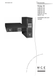
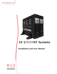
Pulsar MX
4000 RT
5000 RT
Installation and user
manual
P
O
W
E
R
P
D E R
V I
O
R
T H E
U N
I N
T E
R
R
U
P
T
I
B
L
E
34003641FR/AA
- Page 1
34008030EN/AA
- Page 2
Introduction
Thank you for selecting an MGE UPS SYSTEMS product to protect your electrical equipment.
The Pulsar MX range has been designed with the utmost care.
We recommended that you take the time to read this manual to take full advantage of the many features of your UPS
(Uninterruptible Power System)
Warning: this is a class A UPS product. In a domestic environment, this product may cause radio interference, in wich case,
the user may be required to take additional measures.
Output cables should not be longer than 10 meters.
If the device must be installed in overvoltage category III or IV envoronments, additional upstream overvoltage protection must
be provided for.
Before installing Pulsar MX, please read the booklet on the required safety instructions. Then follow the indications in this
manual.
To discover the entire range of MGE UPS SYSTEMS products and the options available for the Pulsar MX range, we invite
you to visit our web site at www.mgeups.com or contact your MGE UPS SYSTEMS representative.
Environmental protection
MGE UPS SYSTEMS has implemented an environmental-protection policy.
Products are developed according to an eco-design approach.
Substances
This product does not contain CFCs, HCFCs or asbestos.
Packing
To improve waste treatment and facilitate recycling, separate the various packing components.
◗ The cardboard we use comprises over 50% of recycled cardboard.
◗ Sacks and bags are made of polyethylene.
◗ Packing materials are recyclable and bear the appropriate identification symbol
.
Material
Abbreviation
Symbol
number
Polyethylene terephthalate
PET
01
High-density polyethylene
HDPE
02
Polyvinyl chloride
PVC
03
Low-density polyethylene
LDPE
04
Polypropylene
PP
05
Polystyrene
PS
06
Follow all local regulations for the disposal of packing materials.
End of life
MGE UPS SYSTEMS will process products at the end of their service life in compliance with local regulations.
MGE UPS SYSTEMS works with companies in charge of collecting and eliminating our products at the end of their service life.
Product
The product is made up of recyclable materials.
Dismantling and destruction must take place in compliance with all local regulations concerning waste.
At the end of its service life, the product must be transported to a processing centre for electrical and electronic waste.
◗
Battery
The product contains lead-acid batteries that must be processed according to applicable local regulations concerning
batteries.
The battery may be removed to comply with regulations and in view of correct disposal.
The "Material Safety Data Sheets" (MSDS) for the batteries are available on our web site*.
◗
(*) For more information or to contact the Product Environmental manager, use the "Environmental Form" on the site:
www.mgeups.com -> About us -> Environment.
34008030EN/AA
- Page 3
Introduction
Pictograms
Important instructions that must always be followed.
Information, advice, help.
Visual indication.
Action.
Audio signal.
In the illustrations on the following pages, the symbols below are used:
LED off
LED on
34008030EN/AA
- Page 4
Contents
1.
Presentation
1.1
Standard positions ...................................................................................................................... 7
1.2
Tower position ................................................................................................................................ 7
Rack position ................................................................................................................................. 7
Rear panels................................................................................................................................... 8
1.3
Pulsar MX 4000 RT / 5000 RT....................................................................................................... 8
Pulsar MX EXB RT (optional battery module)................................................................................ 8
Display and control panel ........................................................................................................... 9
1.4
Options ......................................................................................................................................... 9
Rack mounting kit .......................................................................................................................... 9
ModularEasy MX.......................................................................................................................... 10
Battery extensions for UPS backup times up to 80 minutes .........................................................11
Battery Integration System ...........................................................................................................11
Battery extension cable ................................................................................................................11
2.
3.
4.
Installation
2.1
Unpacking and contents check ................................................................................................ 12
2.2
Internal batteries connection (Battery start-up)........................................................................ 12
2.3
Installation in tower position .................................................................................................... 13
2.4
Installation in rack position ...................................................................................................... 14
2.5
Adjustment of the orientation of the logo and control panel......................................................... 14
UPS module rack mounting ......................................................................................................... 14
UPS or battery module rack mounting ......................................................................................... 15
Communication ports................................................................................................................ 16
2.6
Connection to the RS232 communication port ............................................................................ 16
Connection to the communication port by relays ......................................................................... 16
Remote Power Off communication port ....................................................................................... 17
Installation of communication cards............................................................................................. 17
Required protective devices and cable cross-sections ......................................................... 18
2.7
Recommended upstream protection............................................................................................ 18
Recommended downstream protection ....................................................................................... 18
Required cable cross-sections..................................................................................................... 18
Connection of input/output power cables to UPS terminals ................................................. 19
2.8
Connection of IEC cables to output receptacles .................................................................... 20
Operation
3.1
Initial start-up ............................................................................................................................. 21
3.2
Final start-up sequence............................................................................................................. 21
3.3
Operating modes ....................................................................................................................... 22
3.4
Operation on battery power ...................................................................................................... 23
3.5
Return on Normal AC source.................................................................................................... 23
3.6
UPS shutdown............................................................................................................................ 24
Access to measurements and personalisation data
4.1
Display organisation.................................................................................................................. 25
4.2
Access to measurements.......................................................................................................... 25
4.3
Access to UPS set-up and maintenance using the control panel......................................... 25
4.4
UPS set-up.................................................................................................................................. 26
4.5
Maintenance ............................................................................................................................... 27
4.6
Personalisation using external software ................................................................................. 27
34008030EN/AA
- Page 5
Contents
5.
6.
Troubleshooting
5.1
Troubleshooting LEDS (21) and (22).........................................................................................28
5.2
Troubleshooting not requiring MGE UPS SYSTEMS after-sales support .............................28
5.3
Troubleshooting requiring MGE UPS SYSTEMS after-sales support....................................29
Life Cycle Monitoring (LCM)
6.1
Description..................................................................................................................................30
Get free offers...............................................................................................................................30
Secure your installation power continuity .....................................................................................30
Reset or disable LCM ...................................................................................................................31
7.
8.
34008030EN/AA
- Page 6
Maintenance
7.1
Hot swapping the power sub-module.......................................................................................32
7.2
Hot swapping the battery sub-module .....................................................................................32
7.3
Maintenance on a UPS equipped with the ModularEasy MX module....................................33
7.4
Training centre............................................................................................................................33
Appendices
8.1
Technical specifications ............................................................................................................34
8.2
Glossary ......................................................................................................................................35
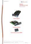
1. Presentation
1.1 Standard positions
Tower position
Dimensions (H x W x D) in mm / Inches
Pulsar MX 4000 RT
444.5 x 131 x 700 /
17.5 x 5.16 x 27.56
Pulsar MX 5000 RT
444.5 x 131 x 700 /
17.5 x 5.16 x 27.56
Pulsar MX EXB RT
444.5 x 131 x 650 /
17.5 x 5.16 x 25.6
Weights in kg / lbs
Pulsar MX 4000 RT
57 / 125
Pulsar MX 5000 RT
57 / 125
Pulsar MX EXB RT
70 / 154
Rack position
Dimensions (H x W x D) in mm / Inches
Pulsar MX 4000 RT
131 x 444.5 x 700 /
5.16 x 17.5 x 27.56
Pulsar MX 5000 RT
131 x 444.5 x 700 /
5.16 x 17.5 x 27.56
Pulsar MX EXB RT
131 x 444.5 x 650 /
5.16 x 17.5 x 25.6
Weights in kg / lbs
Pulsar MX 4000 RT
57 / 125
Pulsar MX 5000 RT
57 / 125
Pulsar MX EXB RT
70 / 154
34008030EN/AA
- Page 7
1. Presentation
1.2 Rear panels
Pulsar MX 4000 RT / 5000 RT
SWITCHED
GROUP 2
SWITCHED
GROUP 1
1
2
7
8
3
4
9
5
6
PARALLEL
11
10
14
12
13
15
RS232
CONTACTS BAT NO. RPO
16
(1) Two groups of 2 programmable (10A)
outlets for connection of equipment
(2) Groups of 4 (10A) outlets for connection of
equipment
(3) Groups of 2 (16A) outlets for connection of
equipment
(4) 12A thermal switch
(5) 20A thermal switch
(6) 12A thermal switch
(7) Output terminal block
(8) Normal AC source terminal block
(9) Connector for additional battery module
(10) Slot for optional communication card
(11) Connector for parallel operation
(12) USB communication port
(13) RS232 communication port
(14) Communication port by relay
(15) Connector for automatic detection of
battery module(s)
(16) Connector for Remote Power Off control
(RPO)
Pulsar MX EXB RT (optional battery module)
BATTERY
CONNECTOR
180Vdc
(17) Connectors for automatic detection of
battery module(s)
(18) Connectors for battery modules (to the
UPS or to the other battery modules)
(19) Battery circuit breaker
18
BATT. NO.
BATTERY BREAKER 50Adc
34008030EN/AA
- Page 8
19
BATTERY
CONNECTOR
180Vdc
18
17
1. Presentation
1.3 Display and control panel
20
21
22
23
ESC
25
26
24
27
30
I
31
(20) Load protected LED
(21) Downgraded operation LED
(22) Load not protected LED
(23) Alphanumeric display
(24) Escape (cancel) button
(25) (26) Function buttons
(scroll down / scroll up)
(27) Enter (confirm) button
(28) UPS OFF button
(29) UPS ON button
(30) Rectifier LED
(31) Battery LED
(32) Inverter LED
(33) Bypass LED
(34) Load powered LED
O
28
32
33
29
34
1.4 Options
Rack mounting kit
Telescopic rails for Pulsar MX RT mounting in 19’’ enclosure with mounting hardware (part number 68002)
35
36
(35) Ear hangup
(36) Rear bracket system for transportation
(37) Telescopic rails, 639 mm to 1005 mm
length (27.36’’ to 39.96’’)
37
34008030EN/AA
- Page 9
1. Presentation
ModularEasy
Pulsar MX ModularEasy enables parallel
operation when combining two Pulsar MX
UPSs. Consequently you can enhance the
availbility level of your equipment (N+1
redundancy). You can also double your
secured power capacity according to your
needs (migration, network extension...).
In the unlikely event a major fault would
occur, the manual maintenance bypass of
Pulsar MX ModularEasy would allow the
UPS maintenance without interrupting your
connected equipment.
In single unit mode, Pulsar MX
ModularEasy combined with one Pulsar MX
UPS adds a second level of availability to
your installation.
The manual bypass mode allows the
replacement of the UPS without any
interruption to the connected equipment in
case of a major fault that would not be related
to the most critical components of the UPS
(i-e front-accessible, hot-swappable Battery
and Power Sub-Modules).
Example of Pulsar MX ModularEasy connected with two UPSs in parallel operation
SWITCHED
GROUP 2
SWITCHED
GROUP 1
SWITCHED
GROUP 2
SWITCHED
GROUP 1
UPS 1
(Pulsar MX RT)
Pulsar MX RT ModularEasy
UPS 2
(Pulsar MX RT)
PARALLEL
PARALLEL
RS232
CONTACTS BAT NO. RPO
RS232
CONTACTS BAT NO. RPO
UPS output to load
AC Normal input
34008030EN/AA
- Page 10
1. Presentation
Battery extensions for UPS backup times up to 80 minutes (at full load)
Pulsar MX RT offers a standard backup time of 5/7 minutes at full load.
To increase backup time, it is possible to connect Pulsar MX EXB RT modules to the UPSs.
Battery extensions for Pulsar MX RT
Pulsar MX
4000 RT /
5000 RT
Pulsar MX 4000 RT:
Pulsar MX 5000 RT:
7 min
5 min
+
Pulsar MX
EXB RT
29 min
22 min
+
Pulsar MX
EXB RT
53 min
41 min
+
Pulsar MX
EXB RT
80 min
62 min
Battery Integration System
The Battery Integration System is intended
for extended backup time configurations to
conveniently stack and secure up to 9
modules on the same cart (swivel wheels with
brakes, leveling feet, seismic side panels,
plates to lock modules and screws included).
Battery extension cable (1,8 m / 6 ft)
This extended battery cable will be used instead of the standard battery cable when battery modules are distant from each
other (located in two different enclosures, for instance).
34008030EN/AA
- Page 11
2. Installation
2.1 Unpacking and contents check
40
42
41
44
43
45
47
49
48
IP=
MAC=00E0D8FF855E
100
10
Reset
46
Card Settings
UPS
data
1 2
ON
RS232 Download
ETHERNET
RS232
66074
(40) Pulsar MX 4000 or 5000 UPS.
(46) Screw driver.
(41) Two sets of tower stands.
(47) Solution-Pac power management suite CD-ROM.
(42) RS232 communications cable
(48) Network Management card (optional, or standard in
NetPack version).
(43) Product documentation.
(44) 4 cable lockers.
(49) 4 IEC 10A output cables.
(45) Telescopic rails for rack enclosure with mounting
hardware (optional, or standard with NetPack version).
Packaging must be destroyed according to waste management standards. Recycling icons are displayed for easy selection.
A dangerous voltage is present inside the power module and the battery module. Any operations to be carried out
on these modules must be done so by qualified staff.
2.2 Internal battery connection (Battery start-up)
1 - Remove the two fixing screws (59) to free
the battery connector.
2 - Push the battery connector so that you can
read "Connected".
3 - Secure the two fixing screws (59).
59
60
34008030EN/AA
- Page 12
2. Installation
2.3 Installation in tower position
Follow steps 1 to 3 to adjust the tower stands for the upright position.
1
1
ESC
150 mm
2
3
2
3
3
3
450 mm
Always keep 150 mm free space behind the UPS rear panel.
The distance between the tower stands should be 450 mm.
34008030EN/AA
- Page 13
2. Installation
2.4 Installation in rack position
Adjustment of the orientation of the logo and control panel
1
2
3
UPS module rack mounting (optional rails required)
Pulsar MX RT is very heavy. To ease its rack integration, we strongly recommend to remove the battery tray as shown below:
2
4
3
3
1
1
x6
1
1 - Remove the 6 fixing screws to free the main front panel bezel.
2 - Place the front panel above the UPS.
3 - Remove the 4 fixing screws on the right side to free the battery sub-module.
4 - Pull the battery sub-module slightly, then lift it to extract it.
34008030EN/AA
- Page 14
2. Installation
UPS or battery module rack mounting (optional rails required)
It is not allowed to install the UPS or battery module in a hermetically closed environment without any exchange of
air.
Follow steps 1 to 4 for rack mounting the UPS onto the rails.
3
3
3
1
3
2
4
1
4
The rails and the necessary mounting hardware are supplied by MGE UPS SYSTEMS.
Note for step 1: it is possible to adjust the position of both front mounting ears.
Rear bracket system (included with rail kits)
To be used if you need to move the rack enclosure with UPS already rack-mounted inside.
34008030EN/AA
- Page 15
2. Installation
2.5 Communication ports
Pulsar MX RT provides 3 communication methods that can be used simultaneously:
◗ 2 COM ports provide RS232 or USB communications using MGE UPS SYSTEMS SHUT protocol. Compatible with most
power management software applications available into the enclosed Solution Pac CD-Rom. Please, note that both ports
cannot be used at the same time.
◗ The output contact port is used for basic signaling or for protection of IT systems like IBM iSeries (formerly AS400) and more.
◗ The slot is compatible with any MGE UPS SYSTEMS communication card (check www.mgeups.com web site for the
complete list of compatible cards).
Connection to the RS 232 communication port
SWITCHED
GROUP 2
1 - Connect the RS232 (42) communications
cable to the serial port on the computer
equipment.
SWITCHED
GROUP 1
2 - Connect the other end of the
communication cable (42) to the RS232 (13)
communications port on the UPS.
The UPS can now communicate with various
MGE UPS SYSTEMS power management
application software. Please note that the
configuration software is included with
Personal Solution Pac for Windows.
42
PARALLEL
RS232
CONTACTS BAT NO. RPO
13
Connection to the communication port by relays (14)
(see page 8)
Pin 1, 2: not used,
Pin 3: remote Power Off signal (5 to 27 V DC, 10 mA max),
◗ Pin 4: operation on mains (not on battery),
◗ Pin 5: user common,
◗ Pin 6: operation on automatic by-pass,
◗ Pin 7: low battery,
◗ Pin 8: load protected,
◗ Pin 9: operation on battery.
n.o.: contact normally open.
n.c.: contact normally closed.
◗
5
4
9
n.c.
n.o.
3
8
n.o.
2
7
◗
1
14
6
n.o.
n.o.
common
When the status is active, the contact between the common (Pin 5) and the relevant information pin is closed.
Output relays specifications
Voltage: 48 V DC max,
◗ Current: 2 A max,
◗ Power: 62,5 VA, 30 W.
Example: for 48 V DC, Imax=625 mA
◗
34008030EN/AA
- Page 16
2. Installation
Remote Power Off communication port (16)
(see page 8)
Installation of a Remote Power Off function must be carried out in compliance with applicable regulations.
In order to fully de-energize devices and Pulsar MX RT with the RPO port, it is necessary:
◗ to use a two-position switch (Normally Open or Closed contact should be held more than 1 second to be taken into account).
(1)
◗ to connect to this RPO switch a device that allows to trip all breaker(s) located upstream
and downstream(2) Pulsar MX
RT. This can be achieved by means of a shunt trip.
(1) : If not, the output devices could be powered again through static switch when the two-position switch is released.
(2) : If not, the output devices will remain powered several seconds after the RPO activation.
Please, notice that the internal batteries will remain connected to the power sub-module after RPO activation.
The cable is not included.
Remote power off contact normally open
Remote power off contact normally closed
RJ12 (6p6c)
RJ12 (6p6c)
654321
654321
5 V DC to 27 V DC
5 V DC to 27 V DC
Signal:
- activation voltage: 5 V DC to 27 V DC.
- current: 10 mA max.
◗
Installation of communication cards (optional, standard with the NetPack version)
SWITCHED
GROUP 2
It is not necessary to shutdown the UPS
before installing a communications card.
SWITCHED
GROUP 1
1 - Remove the slot cover secured by two
screws.
2 - Insert the communications card in the slot.
3 - Secure the card with both screws.
IP=
MAC=00E0D8FF855E
PARALLEL
RS232
100
10
Reset
Communication card (restricted access)
Card Settings
UPS
data
1 2
ON
RS232 Download
ETHERNET
RS232
66074
CONTACTS BAT NO. RPO
34008030EN/AA
- Page 17
2. Installation
2.6 Required protective devices and cable cross-sections
Recommended upstream protection
UPS power rating
Upstream circuit breaker
4000 RT
D curve - 32A
5000 RT
D curve - 32A
The indicated protection ensures
discrimination for each output circuit
downstream of the UPS.
If these recommendations are not followed,
protection discrimination is not achieved and
may result in a potential power interruption to
the connected devices.
2 poles circuit breaker
L
N
G
N
To UPS Normal AC source
L
Recommended downstream protection
UPS power rating
Downstream circuit breaker
4000 RT
Z curve - 10A
C curve - 4A
5000 RT
Z curve - 10A
C curve - 6A
The indicated protection ensures
discrimination for each output circuit
downstream of the UPS.
If these recommendations are not followed,
protection discrimination is not achieved and
may result in a potential power interruption to
the connected devices.
Required cable cross-sections
2
2
Terminal-block cable capacity: 6 mm , solid or stranded wire (maximum 8 mm or AWG 8).
2
2
◗ Capacity for earthing conductor: 6 mm , solid or stranded wire (maximum 8 mm or AWG 8).
◗
34008030EN/AA
- Page 18
2. Installation
2.7 Connection of input/output power cables on UPS terminals
This type of connection must be carried out by qualified electrical personnel.
Before carrying out any connection, check that the battery circuit breaker (19) (see page 8) and that the upstream protection
device (Normal AC source) is open ("0").
◗ Use included insulated ferrules with stranded wires.
◗
◗
1 - Remove the terminal block cover (2
screws) with the included screwdriver.
2 - Insert the Normal AC cable through the
cable gland (8).
3 - Connect the 3 wires to the Normal AC
terminal block.
Always connect first the
earthing wire.
4 - Insert the output cable through the cable
gland (7).
5 - Connect the 3 wires to the output terminal
block.
6 - Refit the terminal block cover and tighten
the cable glands.
7 - Secure the terminal block cover by means
of 2 screws.
8
7
1
3
2
5
8
7
4
6
7
34008030EN/AA
- Page 19
2. Installation
2.8 Connection of IEC cables to output receptacles
2
44
1 - Connect the equipments to the UPS using
the cables (49).
It is preferable to connect the priority
equipments to the four outlets (2) and the non
priority equipments to the four outlets (1) that
can be programmed in pairs (1 and 2).
Connect any high-power devices to the 16 A
outlet (3)
To program shutdown of outlets (2) during
operation on battery power and thus optimise
the available backup time, the MGE UPS
SYSTEMS communication software is
required.
49
1
2 - Fit the connection securing system (44)
that prevents the plugs from being pulled out
accidentally.
3
34008030EN/AA
- Page 20
3. Operation
3.1 Initial start-up
It is essential to contact our Customer Service to ensure that your system is commissionned in complete safety and to benefit
from the manufacturer’s guarantee.
1 - Check that the battery switch (60) (see
section 2.2, page 12) on top cover is
connected.
2 - Set the upstream circuit breaker (not
included) to the "I" position (ON).
22
The equipments are powered via the
Normal AC source, but not protected by
the UPS.
Batteries are recharging, an 8 hour recharge
period is necessary to get full backup time.
ESC
I
33
O
LEDs (22) is ON, LEDs (33) and (34) are
green.
34
UPS personalisation
If UPS personalisation is desired, it is advised to enter the personalisation mode at this time (see the 4.4 "Personalisation"
section).
3.2 Final start-up sequence
20
21
3- Press the "I" button (29) more than 3s.
22
The buzzer beeps once, and after UPS
internal test sequence, the LED (20) is ON.
LEDs (30), (32), (34) are green.
The equipments are protected by the UPS.
If LED (21) or (22) is ON, an alarm has
occurred (see the "troubleshooting" section).
ESC
I
30
32
34
O
29
34008030EN/AA
- Page 21
3. Operation
3.3 Operating modes
Normal mode
This is the standard operating mode, set by
default in the factory.
20
Under normal condition (Normal AC source
available):
LED (20) is ON.
LEDs (30), (32), (34) are green.
ESC
I
30
32
O
The equipments are protected by the UPS.
34
Eco mode
The main advantage of the Eco mode (see
glossary) is that it reduces the consumption
of electrical power.
20
Under normal condition (Normal AC source
available):
LED (20) is ON.
LEDs (32), (34) are green.
ESC
I
32
O
The equipments are supplied in ECO
mode.
34
20
If normal AC source is out of tolerance:
LEDs (20), (21) are ON.
LEDs (30), (32), (34) are green.
21
The equipments are protected by the UPS.
ESC
I
30
34008030EN/AA
- Page 22
32
34
O
3. Operation
3.4 Operation on battery power
When the Normal AC source is not available, the load continues to be protected by the UPS.
Power is supplied by the battery.
Transfer to battery power
20
LEDs (20), (21) are ON.
LEDs (31), (32), (34) are green.
21
The audio alarm beeps every 10 seconds.
The equipments are protected by the UPS
and supplied by the battery.
ESC
I
31
32
O
The display indicates the battery remaining
backup time.
34
Low battery warning
20
LEDs (20), (21) are ON.
LEDs (31), (32), (34) are green.
21
The audio alarm beeps every 3 seconds.
The remaining battery power is low.
ESC
I
31
32
O
Shut down all applications on the connected
equipment because automatic UPS
shutdown is imminent.
34
End of backup time
LED (22) is ON.
LED (34) is red.
22
The audio alarm beeps continuously.
The equipments are not powered.
ESC
I
O
The UPS displays "End of backup time
Battery low".
34
3.5 Return on Normal AC source
After an outage, the UPS restarts automatically when Normal AC source is restored (unless this function has been disabled
via UPS personalisation) and the load is supplied again.
34008030EN/AA
- Page 23
3. Operation
3.6 UPS shutdown
1 - Press the "0" button (28) more than 3s.
22
The buzzer beeps once, and the load is no
longer protected by the UPS. It is powered
via the Normal AC source. If the UPS is set
in frequency converter mode, the
equipments will not be powered.
If the Normal AC source is out of
tolerance, the UPS will generate a 10ms
output calibrated break.
2 - For a full shutdown of UPS and connected
load, the upstream circuit breaker (not
included) should be set to the "0" position.
ESC
I
33
34008030EN/AA
- Page 24
34
O
28
4. Access to measurements and personalisation data
4.1 Display organisation
Status and Alarms
Measurements
UPS input measurements
UPS output measurements
Battery measurements
UPS Set-up
Maintenance
Local settings
Model
Output settings
Alarm History
ON/OFF settings
Manual batt test
Battery settings
Led & Buzzer test
LCM
Statistics
Operation limits
4.2 Access to measurements
Press the scroll button (24) (see section 1.3, page 9) to access measurements for voltage, current, frequency, power output
and battery capacity.
4.3 Access to UPS set-up and maintenance using the control panel (23)
Press the scroll button (25) a number of
times to point the UPS set-up or
Maintenance menu
◗ Press the Enter button (27) to get access.
◗
UPS SET-UP
MAINTENANCE
23
ESC
25
27
I
O
34008030EN/AA
- Page 25
4. Access to measurements and personalisation data
4.4 UPS set-up
Local settings
Function
Factory setting
Options
Language
English
French, German, Italian, Portuguese, Spanish
Date / Time Format
International
(DD-MM-YYYY/HH :MM)
US (MM-DD-YYYY/HH:MM AM/PM)
Date / Time Change
GMT + 1
(Continental Europe)
MM-DD-YYYY/HH :MM adjustable
Audible Alarm
Yes
No
Function
Factory setting
Options
Output Voltage
230 V
200 V / 208 V / 220 V /
240 V / 250 V
Freq Converter
Disable
Enable
Output Frequency
50 Hz
60 Hz
User selectable under frequencyconverter mode
Eco Mode
DisablE
Enable
See glossary
Slew Rate
1 Hz / sec.
0.5 Hz / sec.
Bypass Transfer
If bypass Ac nok?
Yes
No
Transfer to bypass if Normal AC
source is out of tolerance
Interrupt Time
10 ms
20 ms, ...... , 200 ms
Break time calibration during load
transfer on Normal AC source out of
tolerance
Overload Prealarm
105 %
40 %, 50 %, 70 %
Alarm if threshold is overrun
Redundancy Mode
No
Yes
On parallel sequence : Alarm if
redundancy loss
Function
Factory setting
Options
Comments
Cold Start
Disable
Enable
Start on battery
Forced Reboot
Enable
Disable
Enables automatic restart of the
system even if Normal AC source is
restored before the end of the
shutdown sequence
Auto Restart
Enable
Disable
UPS restarts automatically when
Normal AC source is restored
Energy Saving
Disable
Enable
Automatic shutdown on battery if
output load level < 10 %
Sleep Mode
Enable
Disable
Remote Command
Enable
Disable
Output settings
Comments
ON/OFF settings
34008030EN/AA
- Page 26
Enables consideration of shutdown
or restart orders from software to be
authorised
4. Access to measurements and personalisation data
Battery settings
Function
Factory setting
Options
Comments
Auto Battery Test
Everyweek
No test / everyday /
everyweek /everymonth
Low Batt Warning
20%
0 to 100%
1% increment
User Batt Settings
UPS reads number of
battery modules
connected
From 0 to 40 Ah
5 Ah increment
Deep Disch Protect
Yes
No
Protection against deep discharge.
If disable, MGE UPS SYSTEMS
warranty will be void
Function
Sub-Function
Option / Display
Comments
Model
Power Module
SN: xxxxxxxxx
SOFT: xxx
NT: xxx
Serial number
Soft version
Technical level
Read
Description
Date Hour
Alarm xxx
10 alarms can be stored
automatically
Erase
No / Yes
Manual Batt Test
Manual Battery Test
No / Yes
Led & Buzzer Test
Led & Buzzer Test
No / Yes
Life Cycle Monitoring
LCM
Enable / Disable
Life cycling monitoring alarms
Statistics
Auto Statistics
Statistics
Custom Statistics
Reset Date ?
Are you sure ?
You need to register at
www.mgeups.com/Icm to get the
code and get access to free statistics
4.5 Maintenance
Frame
Alarm History
Operation Limits
Operation Limits
Automatic alarms displayed when
UPS is operating near the limits
4.6 Personalisation using external software
Insert the Solution-Pac CD-ROM in the drive.
On the first navigation screen, select "Point to Point solution" and follow the instructions on how to install the Personal
Solution-Pac software.
◗ Then select "Settings", "Advanced settings" and "UPS settings".
Note that only the Windows versions of the Personal Solution-Pac software offer this possibility.
◗
◗
34008030EN/AA
- Page 27
5. Troubleshooting
5.1 Troubleshooting LEDS (21) and (22)
20
If LED (21) is ON:
the equipments are protected by the UPS
but the operation is downgraded.
21
If LED (22) is ON:
the equipments are no longer protected
by the UPS.
22
LOAD PROTECTED
x.xkVA / xxx% LOADED
ENVIRONMENT FAULT
SINGLE UPS
ESC
Press the escape button (24) to stop the
audible alarm.
24
25
27
Note :
In case of "MULTIPLE FAULT", press the
"Enter" button (27) and the scroll button (25)
to get access to further details.
In case of "LCM WARNING", refer to LCM
section (see section 6).
5.2 Troubleshooting not requiring MGE UPS SYSTEMS after-sales support
LOAD PROTECTED
x.xkVA / xxx% LOADED
x x x x x x x x FAULT
SINGLE UPS
ESC
Press the "Enter" button (27) to display the details below :
34008030EN/AA
- Page 28
Displayed details
Signification
Correction
NO BATTERY
The battery is incorrectly connected
Check battery connections
I/O BAD CONNECTION
AC source is not connected to the correct
terminals
Check AC wiring
NO POWER MODULE
The power sub-module is not inserted
Check power sub-module connections (see
section 7.1)
NO BATTERY MODULE
The battery sub-module is incorrectly
connected
Check battery connections (see section 7.2)
INV THERM OVERLOAD
The UPS shuts down automatically because
of a major overload.
Check the power drawn by the connected
devices and disconnect any non-priority
devices.
INVERT LIMITATION
Short circuit conditions on output devices
Check the installation at the UPS output
(wiring, fault equipment)
5. Troubleshooting
5.3 Troubleshooting requiring MGE UPS SYSTEMS after-sales support
LOAD PROTECTED
x.xkVA / xxx% LOADED
x x x x x x x x FAULT
SINGLE UPS
ESC
25
27
Display
Signification
Correction
POWER MODULE
FAULT
Internal power sub-module fault detected.
Use "Enter" button (27) to display details.
Call the after-sales support department.
Follow the power sub-module replacement
procedure (see section 7.1)
BATT MODULE FAULT
Battery fault detected during the battery test.
Use "Enter" button (27) to display details.
Call the after-sales support department.
Follow the battery sub-module and battery
module replacement procedure (see section
7.2)
FRAME FAULT
Internal chassis fault detected.
Use "Enter" button (27) to display details.
Call the after-sales support department.
Follow the frame replacement procedure (see
section 7.1, 7.2)
Note: In case of multiple fault, press the "Enter" button (27) and the scroll button (25) to get access to further details.
Troubleshooting one UPS (or two UPS in parallel) with ModularEasy module:
Indication
Diagnostic
Correction
The equipments are no longer supplied
when the manual bypass on the
ModularEasy module is set on the
Bypass position.
The equipments are connected to the
UPS output instead of the
ModularEasy module output.
Check the wiring(s) between the UPS
and the ModularEasy module (see
ModularEasy install manual).
The equipments are no longer supplied
when the manual bypass on the
ModularEasy module is set on the
Normal position.
The wiring(s) between the UPS and the
ModularEasy module is not correct.
Check the wiring(s) between the UPS
and the ModularEasy module (see
ModularEasy install manual).
The equipments are no longer supplied
if Normal AC source fails
The manual bypass on the
ModularEasy module is set on the
Bypass position.
The wiring(s) between the UPS and the
ModularEasy module is not correct.
Set the manual bypass on the
ModularEasy module to the Normal
position.
Check the wiring(s) between the UPS
and the ModularEasy module (see
ModularEasy install manual).
34008030EN/AA
- Page 29
6. Life Cycle Monitoring (LCM)
6.1 Description
This function, embedded in the UPS, displays messages, on screen and communication channels, at every important
stage of the UPS’s life, allowing you to:
Press the "Enter" button (27) to display LCM
warning details.
LOAD PROTECTED
x.xkVA / xxx% LOADED
LCM WARNING
SINGLE UPS
ESC
27
I
Get free offers
O
LCM warning details
Signification
3 MONTHS FREE
WARRANTY EXTENSION
FOR PRODUCT
REGISTRATION
CONTACT MGE AT
www.mgeups.com/lcm
Get free offer after registration at: www.mgeups.com/lcm
FREE STATISTIC
FEATURE FOR
PRODUCT WEB
REGISTRATION
CONTACT MGE AT
www.mgeups.com/lcm
Get free offer after registration at: www.mgeups.com/lcm
These statistics will allow you to have an accurate follow-up (on the display)
of the major environmental parameters of your installation:
◗ Autonomy, time with mains 2 out of tolerance, overloads number, load level
in %, Battery ambient temperature, time on inverter, time on mains 2
Secure your installation power continuity
Anticipate maintenance actions thanks to automatically displayed warnings while displaying automatic warnings when
maintenance actions need to be planned :
34008030EN/AA
- Page 30
LCM warning details
Signification
FOR A SECURED
START-UP CALL MGE
CONTACT MGE AT
www.mgeups.com/lcm
Entrust your product commissioning to MGE UPS SYSTEMS:
MGE UPS SYSTEMS will check the installation according to local
regulations, in respect of the state of the art.
END OF WARRANTY
SOON
CONTACT MGE AT
www.mgeups.com/lcm
Get your product warranty extension, contacting MGE UPS SYSTEMS at:
www.mgeups.com/lcm
BATTERY CHECK RECOMMENDED
CONTACT MGE AT
www.mgeups.com/lcm
Battery is approaching its reliability end of life. Risk to reduce dramatically
backup time
TECHNICAL CHECK RECOMMENDED
CONTACT MGE AT
www.mgeups.com/lcm
Wearing parts of your product must be checked
ALARM OPERATION LIMITS
XXX
CONTACT MGE AT
www.mgeups.com/lcm
One of the following parameters is close to the limit of your product:
Autonomy, time with mains 2 out of tolerance, overloads load level in %,
battery environment temperature
6. Life Cycle Monitoring (LCM)
Reset or disable LCM
In case of any LCM messages displayed:
For temporary reset: press the escape button (24) more than 3 seconds, into Status and Alarm screen, to cancel temporary
the alarm status.
The alert will be repeated twice each 30 days.
◗ For permanent reset: press the enter button (27) more than 3 seconds, into LCM warning screen, to cancel permanently this
LCM event.
◗
At any time:
To Disable all LCM messages select "disable all" ,into LCM menu with LCD navigation.
Be careful: you will not be aware of any LCM events that can happen on the UPS if you disable all LCM messages.
34008030EN/AA
- Page 31
7. Maintenance
7.1 Hot swapping the power sub-module
This operation must be carried out by qualified electrical personnel only.
This operation can be performed without interrupting the equipments.
Disconnecting the power sub-module :
1 - Remove the 6 fixing screws to free the
main front panel bezel.
2 - Place the front panel above the UPS.
3 - Remove the 4 fixing screws on the left side
to free the power sub-module.
4 - Withdraw the power sub-module.
2
3
3
1
4
1
x6
1
Reconnecting the power sub-module :
◗
Carry out the above instructions in reverse order.
◗
Replace the faulty power sub-module by another one with same power rating (Pulsar MX 4000 or Pulsar MX 5000).
7.2 Hot swapping the battery sub-module
◗
Caution: a battery can cause electrocution and high short circuit currents.
Servicing of batteries should be performed or supervised by personel knowledgeable of batteries and the required
precautions. Keep unauthorized personel away from batteries.
◗ Remove watches, rings, bracelets and all other metal objects from the hands and arms,
◗ Use tools with an insulated handle.
◗ When replacing batteries, replace with the same number of the BB/HR5.5-12 batteries.
◗
This operation can be performed without interrupting the equipments.
Disconnecting the battery sub-module :
1 - Remove the 6 fixing screws to free the
main front panel bezel.
2 - Place the front panel above the UPS.
3 - Remove the 4 fixing screws on the right
side to free the battery sub-module.
4 - Pull the battery sub-module slightly, then
lift it to extract it.
2
4
3
3
1
1
x6
1
34008030EN/AA
- Page 32
7. Maintenance
Reconnecting the battery sub-module :
Carry out the above instructions in reverse order.
◗
To ensure safety and high performance, use only batteries supplied by MGE UPS SYSTEMS.
7.3 Maintenance on a UPS equipped with the ModularEasy MX module
Before any action on the manual bypass (61) located on the ModularEasy module front panel, always check that the
inverter is stopped (press the "0" button more than 3 seconds).
The equipments should be powered via the Normal AC source, and not protected by the UPS.
1
BYPASS
NORMAL
TEST
61
TEST
BYPASS
NORMAL
6
BYPASS
3
NORMAL
TEST
ESC
7
30
32
34
29
I
O
The ModularEasy module makes possible to
service or even replace the UPS without
affecting the connected equipments
(HotSwap function).
Maintenance:
1 - Set the manual bypass (61) to the Bypass
position.
The equipments are supplied directly with
Normal AC source.
2 - Check the UPS main bezel and wait the
LCD stops (30 seconds).
3 - Padlock the manual bypass (61) on
bypass position.
4 - The UPS can now be disconnected and
replaced.
Return to normal operation:
5 - Properly wire the UPS (see section 2), and
connect internal batteries.
6 - Set the manual bypass (61) to the Test
position then to Normal position : the
equipments are powered via the Normal AC
source, but not protected by the UPS..
7 - Push the "I" button (29) till the buzzer
beeps. LED (20) is ON, and LEDs (30), (32)
and (34) (see page 9) are green: the
equipments are protected by the UPS.
Test position:
It is also possible to fully test the UPS before
the manual bypass (61) is set on Normal
position.
To check the UPS, after step 5, follow this
operating method:
6bis - Set the manual bypass (61) to the test
position.
7bis - Push the "I" button (29) till the buzzer
beeps. After UPS Internal test, LED’s (30),
(32) and (22) should be ON: no failure has
been detected.
To return to normal operation:
◗ Push the "0" button (28) more than 3
seconds.
◗ Then follow the operating method from step
6.
34008030EN/AA
- Page 33
7. Maintenance
7.4 Training centre
To fully master operation of your MGE UPS SYSTEMS product and carry out level 1 servicing, see our complete range of
technical training courses, available in both French and English.
34008030EN/AA
50 Hz training centre
60 Hz training centre
MGE UPS SYSTEMS
140 avenue Jean-Kuntzmann
Zirst - Montbonnot St-Martin
38334 St-Ismier Cedex FRANCE
MGE UPS SYSTEMS
1660 Scenic Avenue
Costa Mesa CA 92626
Tel. +33 (0)4 76 18 34 14
Fax +33 (0)4 76 18 45 21
[email protected]
www.mgepowerlearning.com
(Catalogue and registration available on line)
Tel. +1 714 557 1637
Fax +1 714 437 9072
[email protected]
www.mgepowerlearning.com
(Catalogue and registration available on line)
- Page 34
USA
8. Appendices
8.1 Technical specifications
Pulsar MX 4000
Output power
Electrical supply network
◗ Rated input voltage
◗ Input voltage range
◗ Frequency
◗ Power factor
◗ Leakage current
Load output
Voltage
◗ Frequency
◗ Harmonic distortion
◗ Overload capacity
◗
Battery
Environment
Operating temperature range
◗ Relative humidity
◗ Storage temperature range
◗ Altitude
◗
◗
Noise level
Pulsar MX 5000
Pulsar MX EXB
(1)
4000 VA /
3600 W
5000 VA
/
4500 W (2)
Single phase 230 V
120 / 156 V to 280 V (3)
50/60 Hz (autoselection)
> 0.99
7 mA max.
Single phase 230 V ±3% (4)
50/60 Hz ±0,5% (5)
< 3%
105% continuous, 110% 2min,
125% 1min, > 150% 0.5s
15 x 12V - 5 Ah,
sealed lead acid,
maintenance free
15 x 12V - 5 Ah,
sealed lead acid,
maintenance free
Two 15 x 12 V - 5 Ah
strings, sealed lead acid,
maintenance free
0°C to 40°C
20% to 90% (non-condensing)
-25°C to 40°C
0 to 1000 m without derating
< 45 dBA
(1) If the output voltage is 200V - 250V, the output power is 4500VA / 4000W.
(2) With one EXB module or more, the standard output power is 5000VA / 4000W.
(3) Values for 70% / 100% of UPS output.
(4) Programmable: 200V / 208V / 220V / 230V / 240V / 250V using the UPS Config software.
(5) Frequency-converter mode is programmable using the UPS Config software.
34008030EN/AA
- Page 35
8. Appendices
8.2 Glossary
34008030EN/AA
Backup time
Time that the connected equipments can operate on battery power.
Bypass AC source
Source supplying the bypass line. The equipments can be transferred to the bypass line if an
overload occurs on the UPS output, for maintenance or in the event of a malfunction.
ECO mode
Operating mode by which the equipments are supplied directly by the AC source if it is within the
tolerances defined by the user. This mode reduces the consumption of electrical power.
Equipments
Devices or systems connected to the UPS output.
Frequency converter
Operating mode used to convert the AC-power frequency between the UPS input and output
(50 Hz -> 60 Hz or 60 Hz -> 50 Hz).
Low-battery warning
This is a battery-voltage level indicating that battery power is low and that the user must take
action in light of the imminent break in the supply of power to the load.
Manual bypass
Rotary switch controlled by the user, used to connect the equipments directly to the AC source.
Transfer of the equipments to the manual bypass enables UPS maintenance without interrupting
the supply of power to the connected equipments.
Normal AC source
Normal source of power for the UPS.
Normal (double
conversion) mode
The normal UPS operating mode in which the AC source supplies the UPS which in turn supplies
the connected equipments (after electronic double conversion).
Personalisation
It is possible to modify certain UPS parameters set in the factory. Certain UPS functions can also
be modified by the MGE UPS SYSTEMS power management products to better suit user needs.
Programmable
outlets
These outlets can be automatically shut down during operation on battery power (shutdown time
delays can be programmed with the MGE UPS SYSTEMS power management products). The
UPS has two sets of two programmable outlets.
Relay contacts
Contacts supplying information to the user in forme of signals.
UPS
Uninterruptible Power System.
- Page 36
34008030EN/AA
- Page 37
MGE UPS SYSTEMS
140, Avenue Jean Kuntzmann
ZIRST - Montbonnot St Martin
38334 - Saint Ismier Cedex - France
www.mgeups.com
34008030EN/AA
T H E
U N I N T E R R U P T I B L E
P O W E R
P R O V I D E R