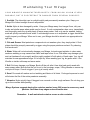
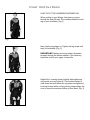
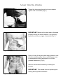
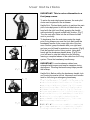
1
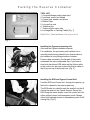
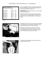
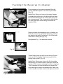
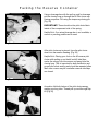
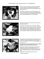
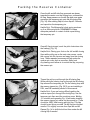
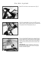
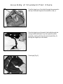
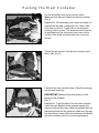
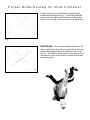
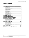
O
W
N
E
R
S
M
A
N
G3
U
A
L
TABLE OF CONTENTS
Introduction . . . . . . . . . . . . . . . . . . . . . . . . . . . . . . . . . . . . . . . . . . . . . . . . . . . . . . 1
User Warning . . . . . . . . . . . . . . . . . . . . . . . . . . . . . . . . . . . . . . . . . . . . . . . . . . . . . 2
Packing Instructions for Ram Air Reserve with Freebag . . . . . . . . . . . . . . . . . . . . . 3
Assembly of RSL (optional) . . . . . . . . . . . . . . . . . . . . . . . . . . . . . . . . . . . . . . . . . 15
The 3-Ring Release System. . . . . . . . . . . . . . . . . . . . . . . . . . . . . . . . . . . . . . . . . 17
Assembly of Centerline Collapsible Pilot Chute. . . . . . . . . . . . . . . . . . . . . . . . . . . 22
Assembly of Standard Pilot Chute . . . . . . . . . . . . . . . . . . . . . . . . . . . . . . . . . . . . 25
Packing Instructions for Main Container . . . . . . . . . . . . . . . . . . . . . . . . . . . . . . . . 26
Proper Routing of Main Pilot Chute Bridle. . . . . . . . . . . . . . . . . . . . . . . . . . . . . . . 29
Packing Instructions for Main Pilot Chute . . . . . . . . . . . . . . . . . . . . . . . . . . . . . . . 30
Maintaining Your Mirage . . . . . . . . . . . . . . . . . . . . . . . . . . . . . . . . . . . . . . . . . . . . 31
Replacement Parts. . . . . . . . . . . . . . . . . . . . . . . . . . . . . . . . . . . . . . . . . . . . . . . . 33
User Instructions . . . . . . . . . . . . . . . . . . . . . . . . . . . . . . . . . . . . . . . . . . . . . . . . . 34
Appendix . . . . . . . . . . . . . . . . . . . . . . . . . . . . . . . . . . . . . . . . . . . . . . . . . . . . . . . 37
INTRODUCTION
Congratulations on your purchase of a Mirage harness/container system.
The Mirage is the finest harness/container system available anywhere,
and with proper care and use it will last for many years. It is the purpose of this
manual to provide you with the information necessary to enable you to care for and use your
Mirage properly. It is our hope you will enjoy your Mirage as much as we enjoyed
building it for you. Should any aspect of the information contained in this manual be
unclear to you, or should you have questions or concerns about your Mirage which are
not addressed by this manual, you are encouraged to contact Mirage Systems Inc.
at the address below or on the back cover of this manual prior to jumping the Mirage.
The purpose of this manual is to familiarize the Mirage owner
with the function and packing procedures of the Mirage system. It is not
a substitute for a course of instruction, nor does it release the user from responsibility
for the use and maintenance of the system. Although packing instructions are included for
the reserve parachute, note that this operation is governed by applicable laws, and
may not be legally conducted by anyone other than a certificated rigger.
Mirage Systems Inc. is not responsible for use of the Mirage with any parts not
specifically supplied by Mirage Systems Inc. for your Mirage, nor for the use of the
Mirage with any other canopies than those specifically mentioned as compatible on
the system information panel inside the main pack tray. If there are any
questions about equipment compatibility, please contact Mirage Systems Inc.
Mirage Systems Inc,
P.O. Box 820
DeLand, FL 32724
[email protected]
WARNING
Low Speed
Parachute
Limited to use from
Airplane under 150 mph
Skydiving is a hazardous activity that can result in injury or death.
Parachutes sometimes malfunction even though they are properly designed, built, assembled,
packed, maintained and used. The results of such malfunctions are sometimes serious injury or death.
If you use your Mirage, or allow someone else to use it, you are acknowledging sport parachuting’s risks
and accepting the fact that the Mirage and / or its components may malfunction.
If you are not willing to accept the risks of sport parachuting, or if you are not willing to accept
the possibility that your Mirage or its components may malfunction and perhaps cause you to be
injured or killed, then you should reconsider your involvement in sport parachuting.
Training and/or experience are required to lower the risk of serious bodily injury or death.
Never use the Mirage unless you have read and understand this warning, and
A. you have completed a “Controlled Program of Instruction” in the use of this equipment or
B. you have read and understand all appropriate flight manuals and packing instructions.
To lower the risk of death, serious bodily injury, canopy damage, container damage and
hard openings, never exceed 130 kts. deployment speed.
Packing the Reserve Container
TOOL LIST
1. Complete Mirage packing data card
2. Lead seal, press, and thread
3. Cypres loop, washer, and silicon
4. Bodkin/T-bar
5. Long pull up cord
6. Temporary pin
7. Temporary pile velcro tabs
8. Leverage Bar or Packing Paddle [Fig. 1]
Helpful Hint: Count and keep track of your tools!
Fig. 1
Installing the Cypres processing unit
(Also see the Cypres installation manual)
For installation, the processing unit is placed into a
specially bolstered and labeled nylon pocket which is
pre-installed in every Mirage reserve container.
Excess cable is stowed in the flat part of the pocket
underneath the velcro-adjustable flap. If you have to
stow both the thinner EOS cable and the thicker cable
to the control unit, be sure to place the thicker cable so
that it lays on top of the thinner one. [Fig. 2]
Fig. 2
Installing the EOS and Cypres Control Unit
Feed the EOS and Control unit through the opening up
the built in channel in the reserve pack tray.
The EOS cable is routed through the small slit on the #1
closing flap and into the Cypres channel. Secure the
EOS using the elastic keeper. Insert the control unit into
either optional control unit transparent pouch. Mirage
offers both backpad window or transparent pouch on #6
closing flap. [Fig. 3]
Fig. 3
Packing the Reserve Container
Attach the square reserve to the container system.
Attach the steering toggles, set the deployment brake
length according to canopy manufacturers instructions.
[Fig. 4]
Fig. 4
Fig. 5
Stow excess reserve canopy steering line in velcro
keeper. Mate toggle to velcro on reserve risers.
Repeat on opposite riser. [Fig. 5 & 6]
Fig. 7
Attach temporary pile velcro tabs to the hook side of
velcro on the line stow pocket of reserve freebag.
Thread Bodkin/T-Bar with pull up cord through center
#2 grommet to the backside of the freebag. [Fig. 7]
Fig. 6
WARNING: Hook velcro may damage suspension
lines.
Helpful Hint: Attach the pull up cord to the safety stow
and Bodkin to hold in place.
Fig. 8
Thread looped end of bridle through pilot chute loops,
then pass freebag through looped end of bridle to form
a larks head knot. Center bridle on pilot chute loops and
cinch very tight. [Fig. 8]
Packing the Reserve Container
Fold canopy in accordance to canopy manufacturers instructions. Mirage Systems recommends P.R.O.
pack style. After flaking and laying the container down,
insure that all suspension lines are placed into the
center of the canopy. Centering the suspension lines
improves deployment. All suspension lines should be
centered the entire length of the cocoon. [Fig. 9]
Fig. 9
Cocoon the canopy to the width of the reserve freebag
mouth lock. Canopies cocooned wider may increase
bulk. [Fig. 10]
Fig. 10
The first fold places the slider grommet on the edge of
the canopy. [Fig. 11]
Helpful Hint: This fold is usually 3-6 inches, depending
on the canopy size.
Fig. 11
Packing the Reserve Container
The second S fold is placed over the first fold. This
begins to create the desired wedge shape of the
reserve container. [Fig. 12]
Helpful Hint: The second fold should be 6-8 inches
overall. The majority of the bulk should be towards the
bottom of the reserve container.
Fig. 12
Pull remaining center cell back creating the MOLAR
shape [Fig. 13]
Helpful Hint: Rolling what is left of the center cell back,
along with distributing this fabric left and right makes a
good MOLAR shape.
Fig. 13
Helpful Hint: Larger canopies tend to have long MOLAR
“ears” and may need to be folded under. The normal
range is 3-6 inches. REMEMBER the Mirage reserve
container prefers the bulk toward the bottom. [Fig. 14]
Fig. 14
Packing the Reserve Container
Place canopy onto the freebag. [Fig. 15]
Helpful Hint: After placing canopy on the bag work one
side at a time into the freebag. Insure the bodkin is
between the MOLAR “ears”.
Fig. 15
Close the freebag mouth lock using the safety stow.
[Fig. 16]
Helpful Hint: The microline lock stows should be 2
inches, Dacron line lock stows may require up to 3”.
Fig. 16
Insert all but 4 inches of the remaining lines into the line
stow pocket in a S fold manner, starting at the very bottom of the pocket.
[Fig. 17]
Helpful Hint: Remember to remove the pile velcro tabs
and mate the velcro in the pocket. Make sure not to trap
any lines in between the velcro halves. To reduce line
bulk, distribute the lines evenly throughout the line pocket.
Fig. 17
Packing the Reserve Container
Here is a suggested reserve closing loop length chart.
Prestretched loops are measured from the washer to
the end of the closing loop. [Fig. 18]
Reserve Closing Loop
Canopy Size Loop Length
PD-113 rsv
PD-126 rsv
PD-143 rsv
PD-160 rsv
PD-176 rsv
PD-193 rsv
PD-218 rsv
PD-253 rsv
3.75"
4.00"
4.25"
4.50"
4.75"
5.25"
6.00"
6.00"
+/+/+/+/+/+/+/+/-
1/4"
1/4"
1/4"
1/4"
1/4"
1/4"
1/4"
1/4"
IMPORTANT: Reserve ripcord pull force must remain
under 22 lbs pull force.
Helpful Hint: A label in the main packing tray lists the
canopies that are compatible with the container. Also
included are more recommendations on closing loop
length.
Fig. 18
Pull Bodkin/T-Bar and pull up cord through the freebag.
Then thread pull up cord through closing loop. Tie off
with bowline knot about 6 inches up. [Fig. 19]
Helpful Hint: Treat pull up cord and top 1/2 inch of
the closing loop with Airtec approved silicon. Airtec
recommends the use of silicon to protect the Cypres
loop. It also helps with reserve pin insertion.
Fig. 19
Place the reserve freebag into the reserve pack tray
and align risers. [Fig. 20]
Fig. 20
Packing the Reserve Container
Push freebag into the reserve container, filling the
corners and make space for the reserve pilot chute.
[Fig. 21]
Helpful Hint: Place your knee on the center freebag
grommet while pulling up on the #4 and #5 side flaps,
and work the canopy into the corners and away from
the center grommet. This is important for bulk distribution and proper pilot chute seating and should be
repeated often.
Fig. 21
Fig. 22
Starting at bridle line attachment point on freebag, lay
bridle as shown in Fig. 22. While distributing, remove
any twists in the bridle. Fold all but 3-4 ft of the bridle
under the #1 closing flap [Fig. 23].
See Appendix Fig. 1 for alternative method
Fig. 23
Thread closing loop and pull up cord through Cypres
cutter and #1 closing flap. Use temporary pin to pin
closing loop in place. [Fig. 24]
Helpful Hint: Placing your foot on the #1 closing flap
while pulling up on the #4 and #5 side flaps, works the
canopy into the corners and away from the closing loop.
This is important for bulk distribution and proper pilot
chute seating and should be repeated often. Main riser
covers may be used after reserve side flaps are closed.
Fig. 24
Packing the Reserve Container
Distribute the remaining 3-4 ft of bridle on top of the #1
closing flap.[Fig. 25]
Fig. 25
Thread pull up cord through the spring pilot chute.
Center the pilot chute base over the #1 closing flap
grommet. [Fig. 26]
Fig. 26
While keeping all pilot chute fabric out of the spring,
compress the pilot chute. [Fig. 27]
Helpful Hint: Holding the pull up cord in mouth will help
control the spring. The pull up cord helps guide the pilot
chute while you compress with your hands.
Fig. 27
Packing the Reserve Container
Using a leverage bar with the pull up cord for leverage,
pull the closing loop up through the #2 Pilot chute cap
closing sequence. Pin using the temporary closing pin.
[Fig. 28]
IMPORTANT: There should not be pilot chute fabric
inside of the compressed coils of the spring.
Helpful Hint: If an actual leverage bar is not available, a
wrench or packing paddle can be used.
Fig. 28
After pilot chute cap is pinned, force the pilot chute
down into the reserve freebag. [Fig. 29]
Helpful Hint: Placing your foot on the #2 reserve pilot
chute while pulling up on the #4 and #5 side flaps,
works the canopy into the corners and away from the
closing loop. This is important for bulk distribution and
proper pilot chute seating and should be repeated often.
Main riser covers may be used after reserve side flaps
are closed.
Fig. 29
Accordion fold both halves of the pilot chute canopy,
making one long tube. Thread pull up cord through flap
#3 [Fig.30]
Fig. 30
Packing the Reserve Container
Place your foot on top edge of the reserve pilot chute
cap. Push the pilot chute towards the bottom while
pulling the #3 flap closed. Remove and replace temporary pin. [Fig. 31]
Helpful Hint: Remember to remove the temporary pin
once the grommets are touching. With adequate pressure to contain the pilot chute, the temporary pin can be
remove and repositioned to the #3 closing flap.
Fig. 31
Once #3 flap is pinned, force the pilot chute down into
the freebag. [Fig. 32]
Helpful Hint: Placing your foot on the #3 closing flap
while pulling up on the #4 and #5 side flaps, works the
canopy into the corners and away from the closing loop.
This is important for bulk distribution and proper pilot
chute seating and should be repeated often. Main riser
covers may be used after reserve side flaps are closed.
Fig. 32
Thread the pull up cord through both #4 and #5 closing
flaps. While using the leverage bar draw #4 and #5
grommets towards the center. Do not remove temporary
pin yet. [Fig. 33]
Important: Do not force grommets into center. Work
gradually using the helpful hint technique
Fig. 33
Helpful Hint: While pulling the flap toward the center,
slap the flap on the reserve side wall seam. This
method will gradually move the grommet closer to the
center without damaging the container. Working both
side
flaps together will also help keep the reserve
container symmetrical.
Packing the Reserve Container
Once the #4 and #5 side flap grommets are drawn
towards the center over the closing loop, unthread the
#5 flap. Keep pressure on the #4 flap and once again
reposition the temporary pin onto the #4 closing flap.
[Fig. 34]. After closing flap #4, close flap #5. Remove
and reposition the temporary pin.
Helpful Hint: The Mirage pilot chute spring produces
up to a 40lb spring force. REMEMBER to keep
adequate pressure to contain it while repositioning
the temporary pin.
Fig. 34
Once #5 flap is pinned, work the pilot chute down into
the freebag. [Fig. 35]
Helpful Hint: Placing your foot on the #4 and #5 closing
flaps while pulling up on the main riser covers, works
the canopy into the corners and away from the closing
loop. These repeated processes will help make the
reserve pin cover have a smoother, flatter look.
Any bowing could allow air to untuck the flap, exposing
the reserve pin.
Fig. 35
Thread the pull up cord through the #6 closing flap.
While pulling the closing loop up through the #6 closing
flap remove the temporary pin. Pin the closing loop with
the reserve ripcord pin. [Fig. 36] If you are installing a
RSL, see RSL assembly section in this manual.
Fig. 36
Helpful Hint: If you are having difficulty getting the
reserve ripcord pin through the closing loop, use the
temporary pin then work the container more. Waiting
15+ minutes and repeating Fig. 34 will make inserting
the reserve ripcord pin easier on the second try. There
should be VERY little bowing with this flap. This flap
should lay as flat as possible The #6 flap has the best
results if it is slightly concave from flaps #4 and #5.
Repeat Fig. 34 to shift the bulk out from under the #6
closing flap if needed.
Packing the Reserve Container
Before sealing the container, count and inspect ALL
tools that were used. [See Fig.1]
Seal reserve pin with 5 lb seal thread. [Fig. 37]
IMPORTANT: Do not forget to replace the completed
packing data card in the proper pocket.
Fig. 37
Close the reserve pin cover using all three tuck tabs.
[Fig.38]
Helpful Hint: Tucking the right (#1), larger tab under first
then the smaller left (#2) will make it easier to close.
Remember to tuck the bottom of the reserve pin cover
into the center flap pocket (#3).
Fig. 38
The RSL System
The Reserve Static Line System (RSL) is optional equipment on the Mirage harness/container. If it is not
installed on your Mirage, you do not need to read this section. If you would like to have the RSL
installed on your Mirage, you may contact Mirage Systems at the address on the back of this manual.
To properly use a system equipped with an RSL, you must be familiar with it’s assembly, operation and
function. You must also receive training from competent instructors prior to using such a system. It is
not the intention of this manual to provide such training.
FUNCTION
The RSL system consists of a lanyard between the left main riser and the reserve ripcord. It is
designed to use the mechanical force of the released main risers after a cutaway to pull the reserve
ripcord pin. It is not guaranteed to function properly and should not be relied on to activate your
reserve.
OPERATION
The RSL is essentially a passive system. A release lanyard is provided to disconnect the system. Use
Assembly of the RSL
Mate 1/2” hook and pile Velcro on the RSL lanyard.
[Fig.1]
Fig. 1
Insert RSL lanyard in the provided spandex pocket
located behind the reserve riser at the large main riser
ring. [Fig. 2]
Helpful Hint: A small screw driver point between the velcro will help guide the RSL lanyard as you push it into
the spandex pocket.
Fig. 2
The RSL System
Mate 5/8” hook Velcro to rear reserve riser. [Fig. 3]
Fig. 3
Attach the snap shackle to the main riser RSL ring and
inspect routing. The RSL shackle must not interfere with
the operation of the 3-Ring System. [Fig. 4]
Fig. 4
Prior to closing flap #6, thread reserve ripcord through
the RSL rings [Fig.5], with the ring on the RSL lanyard
between the two rings on flap #6. After closing flap #6,
neatly tuck the excess lanyard under the reserve closing flap.
IMPORTANT: Proper configuration of the reserve
ripcord through the RSL rings is critical to the proper
function of the RSL system!
Fig. 5
The 3-Ring Release System
3 RING HISTORY
The 3-Ring Release System was invented in
1976. It was the first practical release that
allowed parachutists to jettison their main
canopies in one motion by simply pulling a single
handle. Not only is the 3-Ring easier to operate
than previous canopy release systems, it is also
more reliable. Once the main is jettisoned, the
only things left on the harness are two smooth
rings that cannot snag a deploying reserve. Some
other release systems can - and have - interfered
with the deploying reserve.
MODIFYING THE 3-RING
RELEASE
The great reliability of the 3-Ring system results
from the proper functioning of every one of its
individual components. The owner should not
modify the system in any way, nor should he or
she replace genuine 3-Ring parts with others.
These modifications (among others) may cause
the system to not work properly:
• Substituting risers that don’t have Type 2
sheathing for the locking loop. Don’t use risers
that have loops made of Kevlar or solid cord. The
loop should be white and flat.
• Not using a breakaway handle with cable with
the special yellow coating. This Teflon-impregnated coating is important; other plastic coatings
may cause the cables to bind in the housings or
loops, making it difficult or impossible to jettison
the risers.
• Using a breakaway handle with cables of the
wrong length. The length of the cables is critical
to insure each riser releases in the proper
sequence. There should be a minimum of 5.5” up
to a maximum of 7” of cable past the cable housing end (start measuring where the cable comes
out of the cable housing end). Mirage Systems
trims to 6” as of Nov. 1, 1998. Replacement handles are available from Mirage Systems or your
authorized dealer.
UNDERSTANDING THE 3-RING
RELEASE SYSTEMS
Knowing how the 3-ring release systems works
will help you assemble and inspect it properly.
Begin by peeling the release handle from he
Velcro pocket on the harness. Peeling, rather
than pulling, makes it easier to separate the handle from the webbing. Look behind the risers near
the harness and observe the movement of the
yellow cable as you pull the handle. When the
cable clears the white loop, release is engaged.
Now slowly pull one of the risers off the harness.
As you pull, you’ll notice that the white loop gets
pulled through the grommet by the action of the
smallest ring. Each ring forms a lever with a tento-one mechanical advantage as it passes
through the other. A force of 1,000 pounds on the
large harness ring exerts a force of only 10
pounds on the white loop. (Opening shock usually
totals about 1,000 pounds or 500 pounds on each
riser.)
Because of the mechanical advantage provided
by the 3-Ring design, only a force of approximately one pound on the top ring keeps the release
together. That’s why it’s important to keep foreign
matter like bits of grass and sticks out of the
3-Ring assembly. A small stick in the white loop
could prevent a riser from releasing. It is also
important to understand one of the properties of
the nylon components of the system. When nylon
stays in the same position for a long time, it
begins to conform to that position, or take a “set.”
If the 3-Ring release system stays assembled for
too long, the nylon can become so stiff that the
low drag from a malfunction (such as a streamer)
won’t pull the riser off the ring. The 3-Ring release
system must be disassembled, flexed and
inspected every month. Procedures for this are
listed in the 3 ring maintenance section of this
chapter.
The 3-Ring Release System
USE OF 1-INCH (TYPE 17)
RISERS
Type 17 risers (1” wide) are a high-performance
piece of equipment. High-performance translates
to low durability. We recommend inspecting Type
17 risers frequently for wear, abrasion, cuts,
burns or other damage. In particular, look on the
back of the risers for signs that the webbing is
stretching away from the grommets. Such separation is cause for riser replacement. Change the
risers between 200 and 400 jumps. If you own a
Microlined canopy and the lines are ready for
replacement, change the risers at the same time.
Most of all, remember that these are “high-performance” components that yield low durability. If
you are worried about the durability of Type 17
risers, or will not take the time to inspect them
regularly, we suggest using the standard Type 8
(2”) risers.
USE OF MIRAGE SYSTEMS
ARMORED RISERS
Mirage Systems incorporated the use of our
Armored Risers Feb. 2000. There is an increasing
number of cases of breakaway release cables
malfunctioning because of line twists on high
performance canopies. Twisting risers can trap
the excess release cable inside the risers fabric
channel, inhibiting you from pulling the breakaway
handle. Mirage Systems designed risers with a
hard housing inside the channel on the back of
the riser to stow the excess release cable. These
Armored risers decrease the amount of cable that
is exposed and the hard housing reduces the
likelihood of the riser release cable entrapment
malfunction.
Care and maintenance for the Armored Riser
should include all the same procedures for non
Armored Risers, but should also include routine
inspection of the hard housing channel entrance
hole. Through normal wear the hole should not
increase in diameter. If the housing can be pulled
through the opening, the riser should be replaced.
Assembly of the 3-Ring
Release System
Before assembling the 3-Ring release,
make sure the risers aren’t twisted or
reversed. Lay the Mirage face down,
as you would to pack it. Thread each
cable into its housing and mate the
handle to the harness. The handle
should be positioned as close to the
ends of the housings as possible so
that no cable is exposed.
With the rings of the riser facing forward, pass the
large ring on the end of the riser through the large
harness ring from above. Fold it back toward the
canopy and risers. [Fig.1]
Fig. 1
Thread the smallest ring through the middle ring in the
same way, but make sure it doesn’t pass through the
large ring. [Fig. 2]
Fig. 2
Assembly of the 3-Ring
Release System
Bring the white loop over the small ring only and then
through the riser grommet so it pokes out the back of
the riser. [Fig. 3]
IMPORTANT: For the proper leverage reduction, the
white loop must only travel over the smallest ring.
Fig. 3
Continue threading the white loop through the end fitting on the cable housing. The flat side of the end fitting
should be against the riser.
[Fig. 4]
Fig. 4
Thread the yellow cable through the white loop, making
sure the loop isn’t twisted. Be careful with the cable so
you don’t bend it too sharply or kink it. Insert the free
end in the channel on the back of the riser. There
should be plenty of excess cable with the cutaway
handle securely mated to the harness. [Fig.5]
Repeat the above steps with the other riser.
Fig. 5
The 3-Ring Release System
PRE-JUMP INSPECTION
FOR THE 3-RING RELEASE
Before jumping the Mirage, check the 3-Ring
release system for the following:
1) Each ring passes through only one other ring.
2) The white loop passes through only the
small ring.
3) The white loop passes through the end fitting
on the cable housing without twisting.
4) Nothing passes through the white loop except
the yellow cable.
5) The 3-Ring release handle is securely mated
to the harness, and no cable is visible between
the handle and the cable housings. If your
release handle has a tendency to hide itself
under your main lift web, undo the Velcro and
twist the handle in a counter-clock-wise
rotation (when wearing rig) so the handle will
stick-out and slightly forward for a better grip.
USE OF NON-FACTORY RISERS
If a Mirage is fitted with 3-Ring risers that weren’t
supplied by Mirage Systems, Inc., it is important
that they be checked for proper configuration.
The side view in the illustration show a correctly
built 3-Ring riser attached to the harness ring and
put under moderate tension. Note the following:
1) The rings overlap each other and maintain
metal-to-metal contact between each other.
2) The rings are aligned in parallel planes.
3) The smallest ring is not pulled snug against the
grommet and the white loop is long enough to
give it some play.
4) The white locking loop goes straight down
through the center of the riser grommet on its
way to the cable housing end fitting; it does not
extend past the edge of the grommet hole and
then turn back upwards towards the hole.
IMPORTANT: If your riser configuration does
not match this illustration, the 3-Ring release
might not function correctly. You should contact
a rigger or Mirage Systems before jumping with
those risers.
Assembly of Centerline
Collapsible Pilot Chute
Set out your main canopy, main bag and new pilot
chute. Find the bridle attachment point on your main
canopy [Fig. 1].
Remove the #4 Rapid link from the bridle. Be sure to
unscrew the barrel fully, that will help you to install it
later.
Fig. 1
Feed the end of the bridle through the grommet in the
top of the main bag from the outside in. Fold the bridle if
necessary and push the two short loops of fabric (one
covered in yellow Kevlar tape) through the grommet as
well. About 1” (2.5 cm) should protrude through to the
inside of the main bag [Fig. 2]
Fig. 2
Guide the open #4 Rapid link through the fabric loop
which is backed with yellow Kevlar tape [Fig. 3]
Fig. 3
Assembly of Centerline
Collapsible Pilot Chute
Pass the white collapse line and the bridle through the
Rapid link by passing them through the open gate of the
link. At this point, a small screwdriver or other similar
tool can be used to straighten out the second fabric
loop [Fig. 4]
Fig. 4
Feed the male end of the connector link through the
gap in the second loop until it protrudes through the
loop, the thread the barrel over the male end, closing
the link. Tighten lightly with a wrench [Fig. 5]
Fig. 5
Now pull the loop material over the barrel so the barrel
is covered by the black loop. The collapse line should
exit the bridle between Kevlar and the link should lie as
shown [Fig. 6]
Fig. 6
Assembly of Centerline
Collapsible Pilot Chute
Pass the large loop at the end of the bridle through the
canopy bridle attachment loop, then pass the entire
assembly, starting with the pilot chute handle through
the loop in the bridle. [Fig. 7]
Fig. 7
Cinch tight [Fig. 8]
If these instructions are at all unclear or you have any
questions, CONSULT A RIGGER.
Fig. 8
IMPORTANT: In order for the collapsing pilot
chute to work properly, it must be cocked before
every jump. Failure to cock the pilot chute may result in
a major malfunction. To cock the pilot chute, pull the
pilot chute handle while holding the bridle or stepping
on the packed main bag, in order to extract the collapse
line from the bridle. When it is safe to use, the bridle will
be colored in the window near the pin, not white. Check
that the collapse line shows color during a pin check
prior to every jump. If in doubt ASK A RIGGER.
Assembly of Standard Pilot Chute
Feed the large loop of the bridle through the grommet in
the top of the main bag from the outside in. [Fig. 1]
Fig. 1
Pass the large loop at the end of the bridle through the
canopy bridle attachment loop, then pass the entire
assembly, starting with the pilot chute handle [Fig. 2]
through the large loop in the bridle.
Fig. 2
Cinch tight [Fig. 3]
Fig. 3
Packing the Main Container
The Mirage container system is compatible with practically any ram-air main parachute that will fit into the
container. This manual does not provide specific
instructions for folding the main canopy; that information
must be obtained from the manufacturer’s instruction
manual for each canopy. Fold the canopy and pack it
into the Mirage deployment bag according to those
instructions. Once you have placed the canopy into the
main deployment bag, begin stowing the suspension
lines. Start with the center locking stows and work
towards the outside. [Fig. 1]
Fig. 1
Fig. 2
After making the four locking stows, begin stowing the
lines on the center stows. (Fig. 2) Leave approximately
12-15 inches of suspension line unstowed. This will help
with straighter openings. [Fig. 3]
Helpful Hint: Start your lines stows about 2.5 inches
long and gradually make them smaller after each row.
This helps prevent each line stow from looping over the
row before it and causing a malfunction during deployment.
Fig. 3
Lift the bag over the container, making sure that the bag
remains straight. Stow the risers alongside the reserve
container. Toggles should lie against the reserve container. [Fig. 4]
Helpful Hint: Offsetting the risers side-by-side will
reduce bulk in the riser tray and will give the container
side a smoother look.
Fig. 4
Packing the Main Container
Lay the secondary riser covers over the risers.
Make sure that they are tucked into the riser channel.
[Fig. 5]
Helpful Hint: The secondary riser covers are made of a
material that will take a shape after use. Take a little
extra time on the first 10 pack jobs to insure proper
packing of these covers. This extra time will insure the
proper shaping of the secondary riser covers, which
should not be visible once the main riser covers are
packed.
Fig. 5
Thread the pull-up cord. Use the short closing loop in
the #1 flap. [Fig. 6]
Fig. 6
Fold back the main container flaps. Place the main bag
into the main pack tray.
IMPORTANT: Make sure the line stows go to the
bottom of the container.
[Fig. 7]
Fig. 7
Helpful Hint: To get the best fit into the main container
insert the main bag with bridle grommet against the
reserve container first, then rotate the bag with the lines
towards the bottom of the container. Make sure the bag
fills the bottom corners. With the bulk evenly distributed
the main container will have a smooth appearance.
Packing the Main Container
Close flap #2, being sure the main bridle is routed out
from under the right side of the #2 flap. Mate the 1” velcro on the bridle line to the 1” velcro on the main flap.
Lay excess bridle line to the right. [Fig. 8]
Fig. 8
Close flap #3. [Fig. 9]
Helpful Hint: To help with main container symmetry,
keep the main deployment bag centered or a little to the
left inside the main pack tray. Pulling on the main flaps
while closing has a tendency to push the bag to one
side.
Fig. 9
Close Flap #4, and insert closing pin into loop. Tuck and
route bridle under #4 flap. Run bridle under bridle
protection flap under bottom of container. Check centerline collapsible bridle window to insure that the main
pilot chute is cocked. The centerline should show a colored mark, not solid white. [Fig. 10] Stow the bridle
under the right main side (#4) flap from near the closing
pin down to bottom of the container.
Helpful Hint: No bridle or main pilot chute material
should be exposed. Exposed bridle may result in a
premature main container opening.
Fig. 10
Proper Bridle Routing for Main Container
Proper routing of the main bridle for standard righthanded main deployment [Fig. 1]. Note that the bridle
passes from the right of the container, to the pin, and
back out to the right. It does not cross over the #2 flap.
Fig. 1
IMPORTANT: Do not cross the main bridle from left
side to right side of the main pin cover flap, as this may
cause a slow deployment or a main pilot chute in tow
[Fig. 2]. The bridle must be routed on the same side of
the main pin cover as the bridle is routed into the main
pilot chute pouch.
Incorrect routing
Fig. 2
Packing the Main Pilot Chute
Fig. 1
There are many ways to fold a main pilot chute. Mirage
Systems provides these illustrations to demonstrate one
method.
If using ROL deployment, mate the bridle velcro to the
harness velcro to the mouth of the ROL pouch on the
back of the leg pad.
Fig. 2
Fig. 3
Store excess bridle line on the hand deploy pilot chute
and leave approximately 8” of bridle length. Fold the
pilot chute in half and proceed to fold as in illustrations.
[Fig. 1-5]
Fig. 4
Fig. 5
Insert folded main pilot chute in the spandex pouch.
[Fig. 6]
Helpful Hint: No bridle or main pilot chute material
should be exposed. Exposed bridle may result in a
premature main container opening.
Fig. 6
Maintaining Your Mirage
INTRODUCTION
Your Mirage will last longer, look better and function correctly if it is maintained properly. A Mirage
actually requires very little maintenance unless it is subjected to unusual conditions such as a jump
into salt water or a muddy landing.
INSPECTING YOUR MIRAGE
The best approach to maintaining your rig is to periodically spend a few minutes examining every
detail on it. This inspection should be done at least every month. If any wear or damage is found,
have it repaired immediately by a qualified rigger. Delaying repairs may result in a malfunction.
PARTICULAR ATTENTION SHOULD BE GIVEN TO THESE AREAS:
1 Breakaway System. Refer to the 3-Ring maintenance section in this manual for detailed
information on inspecting the canopy releases.
2 Reserve System. This includes the reserve ripcord, locking loop, pins, handle, housing, container
and associated stitching. You should not attempt any repairs or modifications to any of these items
unless you are a master rigger. You can, however, spot little problems before they become major.
3 Harness. The harness should be inspected periodically for broken stitching or frayed webbing.
Main risers, in particular, are subject to wear. See the 3-Ring maintenance section of this manual.
Type 17 mini risers should be replaced every 200-400 jumps depending on wing loading.
4 Main Container. Inspect the plastic stiffeners in the container flaps and replace any that are broken. Replace any grommets that are badly deformed or are pulling out of their setting. Replace any
worn out spandex pouches, which could result in a premature deployment
5 Main Pilot Chute. Check the center line (the length of nylon tape inside the pilot chute that
extends from the handle to the base) of the main pilot chute. It must be firmly sewn at each end;
there must be no broken stitches or torn fabric. Inspect the seam that joins the pilot chute mesh to
the pilot chute fabric. If the mesh is torn or badly frayed, replace the pilot chute. If your Mirage is
equipped with a collapsing main pilot chute, look for wear in moving parts.
6 Closing Loop. The main container is held shut with a closing loop made of nylon suspension line
sheathing. This loop is subject to wear. If it wears out and breaks, the main canopy may release
prematurely and a malfunction may result. Replace the loop with a duplicate if wear is noticed.
CAUTION: Never jump a Mirage with a worn main or reserve closing loop.
Maintaining Your Mirage
YOUR MIRAGE IS MANUFACTURED MOSTLY FROM NYLON. NYLON IS VERY
DURABLE, BUT IS SUSCEPTIBLE TO DAMAGE FROM SEVERAL SOURCES:
1 Sunlight. The ultraviolet rays in sunlight quickly and permanently weaken nylon. Keep your
Mirage out of direct sunlight as much as possible.
2 Acids. Nylon is also damaged by acids. Keep your Mirage away from hangar floors, dirty car
trunks and similar areas where acids may be found. If such contamination does occur, immediately
and thoroughly wash the rig with plenty of warm soapy water. Until a rig can be washed, baking
soda will quickly neutralize most acids. If acid damage occurs or is suspected, a rigger should thoroughly inspect your Mirage. When not in use, your Mirage should be stored in an appropriate storage bag.
3 Oils and Grease. Most petroleum compounds do not weaken nylon; they simply stain it. Such
stains should be promptly removed by a rigger using the proper petroleum solvent. Dry cleaning
fluid works well.
4 Water. Water will not structurally damage your Mirage, but prolonged agitation in clear water
weakens webbing or may cause some fabric and tape colors to run. Salt water may damage nylon
and rust hardware if not promptly and thoroughly washed off with plenty of fresh water. Your rig will
maintain its new appearance longer if it is kept dry. When washing your rig, be gentle with it. Use
Woolite or similar mild soap and warm water.
5 Soil. Soil may damage your Mirage. Brush off the soil after it has dried and gently wash with
warm soapy water. Be sure that the soil is not in the housings, snaps, 3-Ring release or reserve ripcord pins or loops. Consult a rigger if your rig is heavily soiled.
6 Sand. Fine sand will weaken and cut webbing and fabrics of all kinds. Prolonged exposure to sand
will shorten the life of the entire parachute assembly.
7 Abrasion. Nylon quickly frays if dragged over concrete or other rough surfaces. Do not drag your
rig on the concrete while packing.
Mirage Systems suggests having the container washed every 500 jumps to remove any sand
particles. Sand has sharp edges and accelerates wear.
Remember: A well maintained container means a safer container.
Replacement Parts
Components on any device tend to wear out with repeated use. Risers and pilot chutes are limited
lifetime components. With repeated use the materials break down, losing their structural integrity.
Other parts such as breakaway handles, reserve ripcords, reserve pilot chutes and reserve freebags
at times are lost after an emergency procedure. Container size and serial numbers are necessary to
insure that the proper replacement part is ordered. Please check with your dealer on the current
replacement part prices.
Fig. 1
If you are ordering replacement risers that are different
from what you currently have please give the length
(20’”,22”,24”), color, webbing type (mini or large), toggle
type (Velcro, Velcroless), and hardware type (standard
or Stainless steel) [Fig. 1]
Fig. 2
When ordering a main pilot chute different from the
original, please provide the following information: What
type (standard or centerline collapsible), and what type
of handle (plastic or leather hacky). Centerline pilot
chutes and hackys require color choices. [Fig. 2]
The standard color for breakaway handles is red. Other
colors are available. Embroidery is also available on the
handle. Mirage replacement breakaway handles are
stock lengths, they must be cut to proper length upon
delivery. [Fig. 3 ]
Fig.
Reserve ripcords come in different lengths. Rig size
and serial numbers are very important when ordering
replacement ripcords. Please specify type of ripcord.
(Standard metal Mirage handle or the soft reserve
ripcord handle.) [Fig. 4]
Fig. 4
Reserve freebag and reserve pilot chutes are sometimes lost after the deployment of the reserve container.
When replacing these parts, the container size and
serial number are critical. [Fig. 5]
Fig. 5
User Instructions
HOW TO PUT THE HARNESS/CONTAINER ON.
When putting on your Mirage, first place you arms
through the main lift web. The container should be resting on your shoulders. [Fig.1]
Fig 1
Next, slip the leg straps on. Tighten the leg straps until
they fit comfortably. [Fig. 2]
IMPORTANT: Make sure the leg strap is threaded
properly through the friction adapter. If you have any
questions consult your rigger or instructor.
Fig 2
Helpful Hint: Leaning forward slightly while tightening
will provide an even tighter fit. The container tends to
slide down the back before the leg straps are tightened.
Leaning forward while cinching the leg straps allows the
user to move the container further up their back. [Fig. 3]
Fig 3
User Instructions
Thread the chest strap through the friction adapter.
Tighten until comfortable. [Fig. 4]
Fig 4
IMPORTANT: Make sure the chest strap is threaded
properly through the friction adapter. If you have any
questions consult your rigger or instructor. [Fig. 5}
Fig 5
Once you have the leg and chest strap tightened, stow
all excess webbing away. Excess webbing can cause
an entanglement during deployment or could be
grabbed inadvertently. [Fig.6]
Remove the harness/container by reversing this
process.
IMPORTANT: This manual does not replace proper
training and equipment orientation.
Fig 6
User Instructions
IMPORTANT: This is not an alternative to a
first jump course.
To active the main deployment process, the main pilot
chute must be placed in the air stream.
Helpful Hint: The best body position to perform the main
pilot chute deployment is with the left hand above the
head with the right hand firmly grasping the handle,
while maintaining a good arched body position. [Fig.7]
Toss the main pilot chute into the air stream located
next to your body.
Fig 7
Fig 8
To breakaway from the main risers using the single
point 3-ring release you must first look and locate the
breakaway handle on the users right side of the harness. Second, grasp the handle with your right hand
and use your left hand for assistance as needed. [Fig.8]
Peel the handle from the Velcro pocket. Using both
hands pull the breakaway handle down. [Fig.9] Use
your left hand to strip the cables from the housing,
insuring a complete release of the cable from the 3-ring
system. Throw the breakaway handle away.
IMPORTANT: Loose breakaway cables have
entangled with jumpers and reserve canopies during
deployment. Throwing the handle away helps prevent
that mishap.
Fig 9
Helpful Hint: Before pulling the breakaway handle, look
and locate the reserve ripcord. Harnesses and handles
tend to shift during an emergency breakaway.
Fig 10
Fig 11
To activate the reserve, look and locate the reserve ripcord on the users left side of the harness. Grasp the
reserve ripcord with your left hand. [Fig.10] Use your
right hand for assistance. Pull the reserve ripcord out
and down from the velcro pocket. [Fig.11] For those
who use a soft reserve ripcord, first peel the reserve ripcord from the Velcro pocket, and then pull down. With
both handle types the right hand should strip the
reserve handle cable from the housing. This insures
that the reserve pin has been pulled.
IMPORTANT: Loose reserve cables have entangled
with jumpers and reserve canopies during deployment.
Throwing the handle away helps prevent this mishap.
Appendix
The triangle method is an alternative method of folding
the reserve bride line for better bulk distribution.
Begin by removing all twists in the reserve bridle. Start
by folding the bridle back from freebag attachment point
at 60º. Continue making 60º folds in a triangle pattern.
Every fourth fold alternate folding over with an under
fold. This keeps the bridle from twisting. Continue until
there is 3-4 feet left to be placed on the #1 closing flap.
[Fig. 1]
IMPORTANT: Make sure the closing loop travels
through the center of the triangle.
Fig 1
Notes
________________________________________________________________________________
________________________________________________________________________________
________________________________________________________________________________
________________________________________________________________________________
________________________________________________________________________________
________________________________________________________________________________
________________________________________________________________________________
________________________________________________________________________________
________________________________________________________________________________
________________________________________________________________________________
________________________________________________________________________________
________________________________________________________________________________
________________________________________________________________________________
________________________________________________________________________________
________________________________________________________________________________
________________________________________________________________________________
________________________________________________________________________________
________________________________________________________________________________
________________________________________________________________________________
________________________________________________________________________________
________________________________________________________________________________
________________________________________________________________________________
________________________________________________________________________________
________________________________________________________________________________
MIRAGE G3 HARNESS/CONTAINER SYSTEM
G3
G4
Mirage Systems, Inc.
Post Office Box 820
DeLand, Florida 32721
Shipping Address
1501A Lexington Ave.
DeLand, Florida 32724
www.miragesys.com
phone:386-740-9222 • fax:386-740-9444