1
MIXING CONSOLE
Owner’s Manual
E
ii
Precautions
1. Avoid excessive heat, humidity, dust and
vibration
Keep the unit away from locations where it is
likely to be exposed to high temperatures or
humidity — such as near radiators, stoves, etc.
Also avoid locations which are subject to excessive dust accumulation or vibration which could
cause mechanical damage.
2. Ventilation
The unit has ventilation slots on the top, rear and
bottom panels. Do not block these vents.
3. Avoid physical shocks
Strong physical shocks to the unit can cause damage. Handle it with care.
4. Do not open the case or attempt repairs
or modifications yourself
This product contains no user-serviceable parts.
Refer all maintenance to qualified Yamaha service
personnel. Opening the case and/or tampering
with the internal circuitry voids the warranty.
5. Always power off before making connections
Always turn the power OFF before connecting or
disconnecting cables. This is important to prevent damage to the unit itself as well as other connected equipment.
IMPORTANT NOTICE FOR
THE UNITED KINGDOM
Connecting the Plug and Cord
WARNING: THIS APPARATUS MUST BE EARTHED
IMPORTANT: The wires in this mains lead are coloured in accordance with
the following code:
GREEN-AND-YELLOW
: EARTH
BLUE
: NEUTRAL
BROWN
: LIVE
6. Handle cables carefully
Always plug and unplug cables — including the
AC power cord — by gripping the connector, not
the cord.
7. Clean with a soft dry cloth
Never use solvents such as benzine or thinner to
clean the unit. Wipe clean with a soft, dry cloth.
8. Always use the correct power supply
Make sure that the power supply voltage specified
on the rear panel matches your local AC mains
supply. Also make sure that the AC mains supply
can deliver more than enough current to handle
all equipment used in your system.
Contents
Introduction .......................................1
Features..................................................................1
Front Panel .........................................2
Monaural input channels......................................2
Stereo input channels............................................4
Master Section ...................................6
Variable/Fix select section.....................................6
Mix section ............................................................6
ST (Stereo) section ................................................9
AUX RETURN section........................................10
MATRIX section..................................................11
C-R MONI (Control room monitor) section
PHONES (headphones) section .........................12
TAPE IN section..................................................13
TALKBACK section ............................................14
METER SELECT section.....................................15
Meter bridge ........................................................15
Rear Panel ........................................16
GA Diversity Function ......................19
As the colours of the wires in the mains lead of this apparatus may not
correspond with the coloured markings identifying the terminals in your
plug, proceed as follows:
What is GA Diversity? .........................................19
Setting the GA Diversity function ......................19
The wire which is coloured GREEN and YELLOW must be connected to
the terminal in the plug which is marked by the letter E or by the safety earth
symbol or coloured GREEN and YELLOW.
Specifications ...................................20
The wire which is coloured BLUE must be connected to the terminal which
is marked with the letter N or coloured BLACK.
The wire which is coloured BROWN must be connected to the terminal
which is marked with the letter L or coloured RED.
* This applies only to products distributed by YAMAHA KEMBLE
MUSIC (U.K.) LTD.
GA32/12, GA24/12—Owner’s Manual
General specifications .........................................20
Input specifications .............................................21
Output specifications ..........................................21
Dimensions..........................................................22
Block and Level diagram.....................................23
Introduction
1
Introduction
Thank you for choosing the Yamaha GA32/12 or GA24/12 mixing console. Please read
this manual thoroughly to take best advantage of the console and extend its useful life.
Notes:
This manual has been written on the assumption that you already understand the basic
operation and technical terminology of mixing consoles.
Descriptions of GA24/12 specifications appear in brackets ({}) if they differ from the
GA32/12.
Features
• The GA32/12 provides 28 monaural and 2 stereo
input modules {the GA24/12 provides 20 monaural and 2 stereo input modules}. The output
channels comprise stereo outputs, 10 mix outputs, and two matrix outputs, and support a wide
range of applications, from SR (sound reinforcement) to facility acoustics.
• Each monaural input channel offers a 26 dB pad,
HPF, phase switch, 4-band EQ (HI-MID and LOMID frequencies are variable), and a 100 mmlong full-stroke fader. Also, phantom power can
be turned on and off for every group of four
inputs.
This routing can be used as a conventional group
bus. In this way, you can configure the bus for a
specific purpose.
• The console has two independent matrixes. You
can mix MIX buses 1–4 and the stereo bus individually at the levels you desire and output them
from the MATRIX OUT 1–2 jacks. This routing
can be used as a mix for the foldback or for individual speakers and amplifiers.
• The INSERT I/O jacks are provided for all monaural input channels, the stereo bus, and MIX
buses 1–4. You can insert an external effect processor, if necessary.
• Four stereo AUX returns and TAPE IN jacks are
provided as standard.
• Talkback signals can be sent to any of MIX buses
1–4, MIX buses 5–10, and the stereo bus.
• The master section of the console is located in the
center area of the unit, facilitating operation.
• C-R monitor output enables you to select PFL/
AFL or TAPE IN as a monitoring source.
• The master section provides output channels for
MIX buses 1–10, with EQs and 100 mm-long
faders.
• The console’s sturdy finish and rugged design
assure its durability even under severe conditions
and rough on-site usage.
• Each input channel and four stereo AUX returns
include a PFL switch, and stereo bus, MIX buses
1–10, and Matrix 1–2 has an AFL switch,
enabling you to monitor the input/output
sources quickly.
• Using the GA Diversity function enables you to
set MIX buses 1–4 to Variable mode or Fix mode
individually. In Variable mode, you can change
the level of the signals sent out from the input
channels. This routing can be used as a conventional AUX bus. In Fix mode, the level of the signals sent out from the input channels is fixed.
GA32/12, GA24/12—Owner’s Manual
2
Front Panel
Front Panel
GAIN
26dB
+10
–16
5
–34
–60
PEAK
HIGH
80
1
2
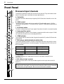
Monaural input channels
3
4
The GA32/12 {GA24/12} has 28 {20} monaural input channels. They are located on both
sides of the master section and feature the same specifications.
A Pad switch
–15
+15
This switch is used to attenuate input signals by 26 dB. Press down the switch to turn the
pad on.
HI-MID
400
8k
–15
+15
LO-MID
80
1.6k
–15
+15
6
LOW
This control knob is used to adjust input sensitivity. The adjustable range is –16 dB to
–60 dB when the pad switch 1 is turned off, and +10 dB to –34 dB when the pad switch is
turned on.
C Ø (Phase) switch
–15
+15
EQ
7
This switch reverses the phase of input signals. Press down this switch to reverse the phase.
D High pass filter switch
M1
0
This high pass filter is used to cut the frequency range below 80 Hz with a slope of 12 dB/
oct. Press down the switch to turn the high pass filter on.
10
M2
8
B GAIN control
ON
0
E PEAK indicator
10
M3
ON
0
9
10
M4
This indicator lights up when the level of signals that pass the EQ reaches 3 dB below the
clipping level.
ON
0
F EQ controls (HIGH/HI-MID/LO-MID/LOW)
10
M5
This 4-band equalizer provides ± 15 dB of cut and boost over each range, with the center
frequencies and types shown in the following table. The frequencies for HI-MID and LOMID are variable.
ON
0
10
M6
PRE
0
10
Band
M7
0
0
10
M8
PRE
0
A
10
M9
0
10
PAN
B
L
C
ST
shelving
400 Hz–8 kHz
peaking (parametric)
LO-MID
80 Hz–1.6 kHz
peaking (parametric)
100 Hz
shelving
G EQ switch
PRE
0
10 kHz
Type
HI-MID
LOW
10
M10
HIGH
Center frequencies
This switch is used to turn equalization on and off. Press down the switch to turn
equalization on.
R
D
ON
PFL
E
H M1–M4 mix level controls
These controls are used to route the post fader signals from the input channel to MIX
buses 1–4.
Note: When you press down the M1–M4 switches to the FIX position in the Variable/
Fix select section (see page 6), the output level of the signals routed to the MIX buses will
be fixed and the corresponding M1–M4 mix level controls will be disabled.
10
5
0
5
10
F
20
30
40
50
60
GA32/12, GA24/12—Owner’s Manual
3
Monaural input channels
I ON switches
These switches are used to turn on and off the signals routed from the input channel to MIX
buses 1–4.
Note: When these switches are set to off, no signals will be sent from the input channel to
the corresponding MIX buses regardless of the setting of the switches in the Variable/Fix
select section (see page 6).
J M5–M10 mix level controls
These controls route the input channel signals to MIX buses 5–10. Use the PRE switches K to
select pre- or post-fader.
K PRE switches
These switches are used to select pre- or post-fader for signals sent from the input channel to
MIX buses 5–10. Each switch is effective for one pair of MIX buses: 5/6, 7/8, or 9/10. When you
turn these switches on, the pre-fader signals will be sent to the corresponding MIX bus pair.
L PAN control
This control is used to set the stereo image of signals sent from the input channel to the ST
(stereo) buses.
M ST (Stereo) switch
When you turn this switch on, input channel signals are sent to the ST buses.
N ON switch
This switch is used to turn on and off the corresponding input channel module. When this
switch is turned off, no signals are sent from the corresponding input channel to the ST buses
and MIX buses 1–10. However, using the PFL switch O will enable you to monitor the signals
via the C-R MONITOR OUT jacks or PHONES jack.
O PFL (Pre-fader Listen) switch
When you turn this switch on, the pre-fader signals of the input channel are routed to the PFL
bus, and you are able to monitor the signals via the C-R MONITOR OUT jacks or PHONES
jack.
P Channel fader
This fader is used to adjust the level of the input channel signals. This fader setting affects the
level of the signals routed to the ST buses, MIX buses 1–4, and MIX buses 5–8 (when the PRE
switches are turned off).
MIX
MIX
PFL
(FIX)
(VARIABLE)
1 2 3 4 1 2 3 4 5 6 7 8 9 10 L R CTL
+48V
PHANTOM
EQ
M1
ø
HIGH
f
GAIN
ON
M2
ON
M3
ON
M4
f
80
26dB
ON
ST
LR
4-Stage EQ
HPF
LOW
HA
LO-MID g
PAD
HI-MID g
INPUT A
1-12,
17-24/17-32
INPUT B
PEAK
ON
INSERT I/O
M5
PRE
M6
M7
PRE
M8
M9
PRE
M10
ST PAN
PFL
Signal flow of the monaural input channel
GA32/12, GA24/12—Owner’s Manual
4
Front Panel
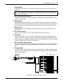
Stereo input channels
GAIN
1
+10
2
–34
PEAK
80
3
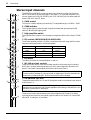
A GAIN control
HIGH
–15
This control is used to adjust input sensitivity. The adjustable range is +10 dB to –34 dB.
+15
B PEAK indicator
HI-MID
–15
+15
4
LO-MID
–15
–15
This high pass filter is used to cut the frequency range below 80 Hz with a slope of 12 dB/
oct.
+15
EQ
5
D EQ controls (HIGH/HI-MID/LO-MID/LOW)
This 4-band equalizer provides ± 15 dB of cut and boost over each range, with the center
frequencies and types shown in the following table.
M1
10
M2
This indicator lights up when the level of signals that have been processed by the EQ
reaches 3 dB below the clipping level.
C High pass filter switch
+15
LOW
0
The GA32/12 and GA24/12 provide two stereo input channel modules. Use the paired
INPUT 13/14 and 15/16 jacks (see page 17, rear panel 5) to input stereo signals. If you
connect signals only to the 13L (MONO) jack or 15L (MONO) jack, the same signal will
be sent t the o M1–4 and ST buses.
ON
Band
6
0
M3
ON
0
M4
0
M5
HIGH
7
3 kHz
peaking
LO-MID
800 Hz
peaking
10
LOW
100 Hz
shelving
E EQ switch
This switch is used to turn the equalization on and off.
F M1–M4 mix level controls
10
M7
0
10
M8
PRE
0
shelving
HI-MID
PRE
0
10 kHz
ON
10
M6
9
These controls are used to route the post fader signals from the stereo input channel to
MIX buses 1–4. When stereo signals are input, the L channel signal will be sent to MIX
buses 1, 3, and the R channel signal will be sent to MIX buses 2 and 4.
10
M9
0
Note: When you press down the M1–M4 switches to the FIX position in the Variable/
Fix select section (see page 6), the output level of signals sent to the MIX buses will be
fixed and the corresponding M1–M4 mix level controls will be disabled.
10
M10
PRE
0
10
BAL
0
L
A
Type
10
ON
0
8
Center frequencies
10
ST
G ON switches (M1–M4)
B
These switches are used to turn on and off the signals routed from the stereo input channel
to MIX buses 1–4.
C
Note: When these switches are set to off, no signals are sent from the stereo input
channel to the corresponding MIX buses regardless of the setting of the switches in the
Variable/Fix select section (see page 6).
R
ON
PFL
10
5
H M5–M10 mix level controls
0
5
10
D
These control knobs route the stereo input channel signals to MIX buses 5–10. Stereo
input signals are mixed into a monaural signal and sent to MIX buses 5–10. Use the PRE
switches 9 to select pre- or post-fader.
20
30
40
50
60
GA32/12, GA24/12—Owner’s Manual
Stereo input channels
5
I PRE (Pre-fader) switches
These switches are used to select pre- or post-fader for signals sent from the stereo input
channel to MIX buses 5–10. Each switch is effective for one pair of MIX buses:5/6, 7/8, or 9/10.
When you turn these switches on, the pre-fader signals are sent to the corresponding MIX bus
pair.
J BAL (Balance) control
This control is used to adjust the left and right balance of signals sent from the stereo input
channel to the ST bus.
K ST (Stereo) switch
When you turn this switch on, the stereo input channel signals will be sent to the ST bus. If you
connect monaural signals to the 13L (MONO) jack or 15L (MONO) jack (see page 17, rear
panel 5), the same signals will be sent to both L and R channels.
L ON switch
This switch is used to turn on and off the corresponding stereo input channel. When this switch
is turned off, no signals are sent to the ST bus and MIX buses 1–10. However, using the PFL
switch M will enable you to monitor the signals via the C-R MONITOR OUT jacks or
PHONEs jack.
M PFL (Pre-fader listen) switch
When you turn this switch on, the pre-fader signals of the stereo input channel are routed to
the PFL bus, and you can monitor the signals via the C-R MONITOR OUT jacks or PHONES
jack.
N Channel fader
This fader is used to adjust the level of the stereo input channel signals. This fader setting affects
the level of the signals routed to the ST bus, MIX buses 1–4, and MIX buses 5–8 (when the PRE
switches are turned off).
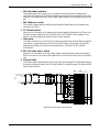
MIX
MIX
(FIX)
(VARIABLE)
PFL
1 2 3 4 1 2 3 4 5 6 7 8 9 10 L R CTL
PFL
14R,
16R
PAD
HA
HPF
PEAK
EQ
LOW
HIGH
80
14/13,
16/15
4-Stage EQ
HPF
LO-MID
HA
HI-MID
PAD
GAIN
13L(MONO),
15L(MONO)
ST
LR
ON
ON
M1
ON
M2
ON
M3
ON
M4
4-Stage EQ
PRE M5
M6
PRE M7
M8
PRE M9
M10
ST
BAL
PFL
Signal flow of the stereo input channel
GA32/12, GA24/12—Owner’s Manual
6
Master Section
Master Section
Variable/Fix select section
The GA32/12 and GA24/12 feature a GA (Group/Aux) diversity function, which enables you to
use the MIX bus 1–4 signals as group bus signals or AUX bus signals. This section of the console
allows you to select whether you wish to use MIX buses 1–4 as group buses or AUX buses.
A M1–M4 switches
These switches are used to select whether the level of signals sent from the input channels to
MIX buses 1–4 will be fixed (FIX) or variable (VARIABLE).
■ When FIX is on:
VARIABLE /
The selected MIX bus(es) function as a group bus. The
level of the signal from each input channel will be fixed,
and the M1–M4 mix level controls of the input channels
that correspond to the MIX buses will be disabled.
FIX
M1
FIX
M2
FIX
1
■ When FIX is off:
M3
FIX
The selected MIX bus(es) function as an AUX bus. Signals
that pass through the M1–M4 mix level controls of each
input channel (see page 2, monaural input channel 8, and
page 4, stereo input channel 6) are sent to the
corresponding MIX buses.
M4
FIX
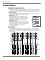
Mix section
This section consists of the output channels that handle MIX bus 1–10 signals individually.
Signals that pass these output channels are output from MIX OUT 1–10 jacks (see page 17, rear
panel 6), and also routed to the AFL bus. MIX bus 1–4 signals are also routed to the ST bus
and Matrixes 1/2.
HIGH
1
HIGH
–15
+15
MID
300
6k
–15
+15
+15
–15
+15
EQ
PAN
R
TO ST
5
300
6k
–15
+15
–15
+15
–15
+15
EQ
PAN
L
R
HIGH
–15
+15
MID
300
6k
–15
+15
LOW
TO ST
+15
EQ
L
R
TO ST
–15
+15
MID
300
6k
–15
+15
LOW
–15
PAN
HIGH
+15
EQ
L
–15
+15
MID
300
6k
–15
+15
LOW
–15
PAN
HIGH
+15
–15
+15
MID
300
6k
–15
+15
LOW
–15
HIGH
+15
–15
+15
MID
300
6k
–15
+15
LOW
–15
HIGH
+15
–15
+15
MID
300
6k
–15
+15
LOW
–15
HIGH
300
6k
–15
+15
LOW
–15
+15
–15
+15
MID
300
6k
–15
+15
–15
+15
–15
+15
EQ
EQ
EQ
EQ
EQ
EQ
TO ST
AFL
AFL
AFL
AFL
AFL
AFL
AFL
AFL
10
10
10
10
10
10
10
10
10
10
5
5
5
5
5
5
5
5
5
5
0
0
0
0
0
0
0
0
0
0
5
5
5
5
5
5
5
5
5
5
10
10
10
10
10
10
10
10
10
10
20
20
20
20
20
20
20
20
20
20
30
30
30
30
30
30
30
30
30
30
40
40
40
40
40
40
40
40
40
40
50
60
50
60
50
60
50
60
50
60
50
60
50
60
50
60
50
60
50
60
M2
2
R
AFL
M1
1
LOW
AFL
6
GA32/12, GA24/12—Owner’s Manual
HIGH
MID
LOW
L
4
–15
MID
LOW
2
3
HIGH
M3
M4
M5
M6
M7
M8
M9
M10
5
6
Mix section
7
■ M1–M4
These modules function as output channels for either a group bus or an AUX bus, depending
on the setting of the switches in the Variable/Fix select section. The MIX bus 1–4 signals that
pass these output channels can be routed to MIX OUT 1–4 jacks, ST bus, AFL bus, and
Matrixes 1/2.
■ M5–M10
These modules function as output channels for an AUX bus. The MIX bus 5–10 signals that
pass these output channels can be routed to MIX OUT 5–10 jacks and AFL bus.
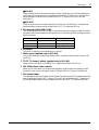
A EQ controls (HIGH/MID/LOW)
This 3-band equalizer provides ±15 dB of cut and boost over each frequency range of the MIX
bus signals, with center frequencies and types shown in the following table. The frequencies for
MID are variable.
Band
HIGH
Center frequencies
10 kHz
MID
300–6 kHz
LOW
100 Hz
Type
shelving
peaking (parametric)
shelving
B EQ switch
This switch is used to turn the equalization on and off.
C PAN control (applied only to M1–M4)
This control allows you to adjust the stereo position of signals routed from MIX buses 1–4 to
the ST bus.
D TO ST (To stereo) switch (applied only to M1–M4)
When you turn this switch on, the MIX bus 1–4 signals will be sent to the ST bus.
E AFL (After-Fader Listen) switch
When you turn this switch on, the post-fader signals in the MIX buses are routed to the AFL
bus, and you can monitor the signals via the C-R MONITOR OUT jacks or PHONES jack.
F Mix master fader
This fader adjusts the output level of the MIX buses. The settings of the M1–M4 faders affect the
level of signals sent to MIX OUT 1–4 jacks, ST bus, AFL bus, and Matrixes 1/2. The settings of
the M5–M10 faders affect the level of signals sent to the MIX OUT 5–10 jacks and AFL bus.
GA32/12, GA24/12—Owner’s Manual
8
Master Section
MIX
MIX
(FIX)
(VARIABLE)
PFL
1 2 3 4 1 2 3 4 5 6 7 8 9 10 L R CTL
FIX
3-Stage EQ
TO ST PAN
LOW
f
MID
HIGH
MIX
INSERT
I/O 1
MIX
ST
OUT 1 L R
EQ
g
VARIABLE/FIX
AFL
to AFL
to MTRX
MIX OUT 2-4: Same as MIX OUT 1
MIX
OUT 5
EQ
LOW
g
MID
HIGH
f
3-Stage EQ
to AFL
AFL
MIX OUT 6-10: Same as MIX OUT 5
Signal flow in the Variable/Fix select section and Mix section
GA32/12, GA24/12—Owner’s Manual
ST (Stereo) section
9
ST (Stereo) section
This section enables you to control the ST bus signals output from the ST1 OUT jacks (see
page 17, rear panel 9) and ST2 OUT jacks (see page 17, rear panel J).
A POST ST1 (Post stereo 1) switch
POST ST1
MONO
LEVEL
0
1
This switch toggles between pre- and post-fader for signals output from the ST2 OUT jacks.
When you turn this switch on, signals that passed the ST fader are output from the ST2 OUT
jacks. When you turn the switch off, the ST fader setting does not affect signals output from the
ST2 OUT jacks.
2
B MONO (Monaural) switch
3
When you turn this switch on, the ST bus signals will be mixed into a monaural signal and
output from the ST2 OUT jacks. This switch setting does not affect signals output from the ST1
OUT jacks.
10
ST2
C LEVEL control
AFL
4
This control enables you to adjust the output level of signals at the ST2 OUT jacks. It does not
affect the level of signals output from the ST1 OUT jacks.
10
D AFL (After-fader Listen) switch
5
When you turn this switch on, the ST bus post-fader signals are routed to the AFL bus, and you
can monitor the signals via the C-R MONITOR OUT jacks or PHONES jack.
0
5
10
20
30
40
5
E ST (Stereo) fader
This fader enables you to adjust the final output level of the ST bus signals. This fader setting
affects the level of the signals routed to the ST1 OUT jacks, ST2 OUT jacks (when the POST
ST1 switch is turned on), and the AFL bus.
50
60
L
ST
LR
R
ST1
REC
OUT
ST
INSERT
I/O L
L
ST1
OUT
AFL
LR
R
ST
INSERT
I/O R
AFL
POST
ST1
L
MONO LEVEL
ST2
OUT
R
Signal flow in the ST section
GA32/12, GA24/12—Owner’s Manual
10
Master Section
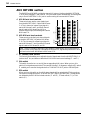
AUX RETURN section
The GA32/12 and GA24/12 provide four stereo AUX returns. Use the paired AUX RETURN
1–4 L/R jacks (see page 17, rear panel 8) to input stereo signals. Alternatively, connect signals
only to the AUX RETURN 1–4’s L jack to use the routing as a monaural AUX return.
A M1–M4 mix level controls
These controls are used to route signals input
from the AUX RETURN 1–2 jacks to MIX buses
1–4. The L channel of a stereo input signal is
sent to MIX buses 1 and 3, and the R channel
signal is sent to MIX buses 2 and 4. For a
monaural signal input, the same signal is sent to
MIX buses 1–4.
M5
0
10
M6
0
M1
0
M1
10
M2
1
B M5–M10 mix level controls
These controls route the input channel signals
at the AUX RETURN 3–4 jacks to MIX buses
5–10. The L channel of a stereo input signal is
sent to MIX buses 5, 7, and 9, and the R channel
signal is sent to MIX buses 6, 8, and 10.
M5
0
10
M3
0
3
10
ON
0
0
10
0
10
1 PFL
10
0
10
0
10
0
10
ON
10
0
ON
0
10
0
2
10
0
10
M10
10
ST
0
10
M9
M10
10
0
M8
M9
ST
10
0
10
M7
M8
M4
ST
0
4
10
M3
M4
0
0
10
M7
M2
0
M6
0
10
ST
10
2 PFL
3 PFL
AUX RETURN
0
ON
10
5
4 PFL
Note: The M1–M4 switch settings in the Variable/Fix select section do not affect the M1–
M10 mix level control settings. If the switches are set to FIX, signals that pass the M1–M10
mix level controls will still be sent to MIX buses 1–10.
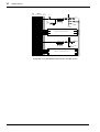
C ST (Stereo) level control
This control knob enables you to adjust the level of signals sent from the AUX RETURN 1–4
jacks to the ST bus, and does not affect the M1–M10 mix level control settings ( 1 and 2).
D ON switch
This switch is used to turn on and off the corresponding AUX return. When you turn this
switch off, no signals are sent to the ST bus and MIX buses 1–10. However, using the PFL switch
5 enables you to monitor the signals via the C-R MONITOR OUT jacks or PHONES jack.
E PFL switch
When you turn this switch on, the AUX return signals will be routed to the PFL bus, and you
can monitor the signals via the C-R MONITOR OUT jacks or PHONES jack. The signals are
not affected by the M1–M10 mix level controls (1 and 2), ST level control (3), or ON
switch (4).
GA32/12, GA24/12—Owner’s Manual
MATRIX section
MIX
MIX
PFL
(FIX)
(VARIABLE)
1 2 3 4 1 2 3 4 5 6 7 8 9 10 L CTL
1L(MONO),
2L(MONO)
11
ST
LR
M1
M2
ON
M3
1R,
2R
M4
ST
AUX RETURN
PFL
3L(MONO),
4L(MONO)
M5
M6
ON
M7
3R,
4R
M8
M9
M10
ST
PFL
Signal flow in the AUX RETURN section
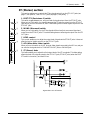
MATRIX section
The GA32/12 and GA24/12 provide two matrix modules that allow you to mix MIX buses 1–4
and ST bus signals at desired levels. Matrix 1–2 signals are output in monaural via the MATRIX
OUT 1–2 jacks (rear panel K).
A M1–M4 level controls
M1
These control knobs enable you to adjust the input level of MIX bus
1–4 post-fader signals.
1
B L/R controls
These control knobs enable you to adjust the input level of the ST bus
post-fader signals for the L channel and R channel independently.
M1
0
0
M2
M2
0
0
M3
M3
0
0
M4
M4
0
0
L
C LEVEL control
This control knob enables you to adjust the output level of Matrix 1–2 signals. 2
D ON switch
L
0
0
R
R
0
0
LEVEL
This switch turns on and off Matrixes 1–2. When you turn this switch
off, the corresponding matrix signal is not output from the MATRIX
OUT jack. The signal is not sent to the AFL bus, either.
LEVEL
3
0
4
ON
10
0
1 AFL
ON
10
2 AFL
MATRIX
E AFL (After-fader Listen) switch
5
When you turn this switch on, the matrix 1–2 post-fader signals are
sent to the AFL bus. You can monitor the signals via the C-R MONITOR OUT jacks or
PHONES jack. However, this switch will be disabled if the ON switch ( 4) is turned off.
AFL
LR
ST
LR
from 1
MIX OUT
2
M1
3
AFL
M2
4
MATRIX
OUT
1,2
M3
M4
L
ON LEVEL
to Meter
R
Signal flow in the MATRIX section
GA32/12, GA24/12—Owner’s Manual
12
Master Section
C-R MONI (Control room monitor) section
PHONES (headphones) section
This section enables you to control signals monitored via the C-R MONITOR OUT jacks (see
page 18, rear panel M) and the PHONES jack on the front panel (C-R MONI section/
PHONES section 6).
A Monitor source select switch
PFL/AFL
TAPE IN
PFL
LEVEL
1
2
3
0
10
4
ON
C-R MONI
LEVEL
0
5
10
This switch enables you to select the type of signal to monitor via the C-R MONITOR OUT
jacks and the PHONES jack.
■ When the switch is set to PFL/AFL (
)
You will monitor PFL signals (signals routed from input channels/AUX returns to the PFL bus)
or AFL signals (signals routed from MIX buses 1–10/ST buses/MATRIX 1–2 to the AFL bus).
If any one of the PFL switches for the input channels/AUX returns is turned on, the PFL
indicator 2 will light up. In this case, the PFL bus signals (not the AFL bus signals) are routed
to the C-R MONITOR OUT jacks and PHONES jack. If all the PFL switches are turned off, the
AFL bus signals are sent to the C-R MONITOR OUT jacks and PHONES jack.
Note: If you turn on any one of the PFL switches for the input channels/AUX returns while
monitoring the AFL bus signal, the switching circuit will switch the signal to the PFL bus
signal.
■ When the switch is set to TAPE IN (
)
You can monitor the signals input from the TAPE IN jacks (see page 18, rear panel N).
B PFL (Pre-fader Listen) indicator
This indicator lights up when any one of the PFL switches for the input channels/AUX returns
is turned on, indicating that the PFL bus signal is currently being monitored.
6
C LEVEL control
This control enables you to adjust the level of signals output from the C-R MONITOR OUT
jacks. This setting does not affect the signal level at the PHONES jack.
D ON switch
PHONES
This switch turns on and off the monitoring signals output from the C-R MONITOR OUT
jacks. It does not affect signals at the PHONES jack.
E LEVEL (Headphones level) control
This control enables you to adjust the level of signals output from the PHONES jack. This
setting does not affect the signal level at the C-R MONITOR OUT jacks.
F PHONES (Headphones) jack
Connect monitoring stereo headphones here. See
the figure on the right for wiring.
Tip (left)
1/4" TRS phone plug
Ring (right)
Sleeve (ground)
GA32/12, GA24/12—Owner’s Manual
TAPE IN section
13
TAPE IN section
This section enables you to control line-level signals input from the TAPE IN jacks. Input
signals from the TAPE IN jacks can be routed to the ST bus or directly to the C-R MONITOR
OUT jacks and PHONES jack.
A ST (Stereo) control
ST
0
1
10
ON
TAPE IN
2
This control knob determines the level of input signals at the TAPE IN jacks that are sent to on
the ST buses.
B ON switch
This switch turns on and off the signals sent from the TAPE IN jacks to the ST bus. This switch
setting does not affect signals (input from the TAPE IN jacks) that are monitored via the C-R
MONITOR OUT jacks and PHONES jack.
Note: Set the Monitor source select switch (C-R MONI section 1) in the C-R MONI section
to “TAPE IN” to monitor the TAPE IN signals via the C-R MONITOR OUT jacks and
PHONES jack.
PFL
L R CTL
ST
LR
from MTRX
12
PFL•AFL/TAPE
MATRIX
from AFL
PFL
PFL/AFL
TAPE IN
L
ON
LEVEL
R
LEVEL
TAPE
IN
C-R
MONITOR
OUT
PHONES
L
ON ST
R
Signal flow in the C-R MONI section, PHONES section, and TAPE IN section
GA32/12, GA24/12—Owner’s Manual
14
Master Section
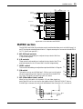
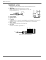
TALKBACK section
This section is used to route talkback signals to the MIX buses and the ST bus.
A INPUT jack
This XLR-3-31 unbalanced input jack is used to connect a
talkback microphone with an output impedance of 50–600Ω. See
the figure below for wiring.
1
1 (ground)
3 (cold)
Male XLR plug
INPUT
2
3
2 (hot)
M1-M4
5
0
10
M5-M10
4
B M1-M4 switch
C M5-M10 switch
D ST switch
LEVEL
ST
ON
6
TALKBACK
These switches (2–4) are used to send talkback signals to MIX buses 1–4, MIX buses 5–10,
and ST bus. You can turn the switches on or off independently for each destination.
E LEVEL control
This control knob is used to adjust the talkback level.
F ON switch
This switch turns talkback signals on and off.
MIX
MIX
(FIX)
(VARIABLE)
PFL
1 2 3 4 1 2 3 4 5 6 7 8 9 10 L R CTL
M1-M4
INPUT
HA
LEVEL
ON
M5-M10
ST
Signal flow in the TALKBACK section
GA32/12, GA24/12—Owner’s Manual
ST
LR
METER SELECT section
15
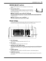
METER SELECT section
You can select the signal source to be displayed in the Meter bridge
section.
A Source select switch
This switch enables you to select the signal source to be displayed on
the MATRIX (PFL•AFL/TAPE) meter (Meter bridge 3) in the right
corner of the level meter.
■ When the switch is set to PFL-AFL/TAPE (
1
PFL•AFL/TAPE
MATRIX
METER SELECT
)
The meter indicates either the PFL/AFL bus output level or the input level of the signals sent
from the TAPE IN jacks, depending on the setting of the Monitor source select switch in the
C-R MONI section.
■ When the switch is set to MATRIX (
)
The meter indicates the output level of Matrix 1 and 2.
Meter bridge
This peak level meter indicates the output level of the MIX buses, ST bus, Matrixes 1/2, PFL
bus, and AFL bus, and the level of the signal input from the TAPE IN jacks.
1
2
PEAK
+8
+5
+3
+1
0
–1
–3
–5
–7
–10
–15
–20
3
PEAK
+8
+5
+3
+1
0
–1
–3
–5
–7
–10
–15
–20
M1
M2
M3
M4
M5
M6
M7
M8
M9
M10
4
PEAK
+8
+5
+3
+1
0
–1
–3
–5
–7
–10
–15
–20
L
R
ST1
1
2
MATRIX
L
R
PFL•AFL / TAPE
POWER
5
PHANTOM
A M1–M10 meters
These meters indicate the output level of MIX OUT 1–10.
B ST1 meters
These meters indicate the output level of ST1 OUT.
C MATRIX (PFL•AFL/TAPE) meters
These meters indicate the PFL/AFL bus level, input level of signals sent from the TAPE IN jacks,
or the output level of Matrixes 1/2, depending on the selection made in the METER SELECT
section.
D POWER indicator
When the power to the GA32/12 (or GA24/12) is turned on, this indicator lights up.
E PHANTOM indicator
This indicator lights up when any of the phantom power supplies (see page 16, rear panel 4)
are turned on.
GA32/12, GA24/12—Owner’s Manual
16
Rear Panel
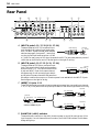
Rear Panel
C
A
C-R MONITOR OUT +4dB
R
0 9
MATRIX OUT +4dB
L
2
8
ST2 OUT +4dB
1
R
3
4
AUX RETURN +4dB
4L (MONO)
3L (MONO)
2L (MONO)
1L (MONO)
4R
3R
2R
1R
L
PHANTOM (+48V)
D
E
R
L
ST INSERT I/O 0dB
R
TAPE IN –10dBV
R
ST1 OUT +4dB
L
MIX INSERT I/O 0dB
3
4
9
7
6
5
4
3
2
1
16R
14R
1
MIX OUT +4dB
B
ON
11
INSERT I/O
0dB
10
INSERT I/O
0dB
9
INSERT I/O
0dB
INSERT I/O
2
OUT IN
8
12
INSERT I/O
0dB
REC OUT –10dBV
10
OFF
15L (MONO) 13L (MONO)
L
7 6
5
INPUT
INPUT
INPUT
INPUT
B
B
B
B
INPUT
INPUT
INPUT
INPUT
A
A
A
A
12
A INPUT A jacks 1–12, 17–32 {1–12, 17–24}
These are balanced, XLR-3-31 monaural input
1 (ground)
Male XLR plug
3 (cold)
jacks. Usually their nominal input levels range
from –16 dB to –60 dB. However, when the pad
switches (see page 2, front panel 1) are turned
2 (hot)
on, the nominal input levels range from +10 dB
to –34 dB. For every group of four input channels, the INPUT A jacks have phantom power of
+48 V that can be turned on and off. See the figure on the right for wiring.
B INPUT B jacks 1–12, 17–32 {1–12, 17–24}
These are balanced TRS phone, monaural input
Tip (hot)
jacks. Their nominal input levels are the same as
1/4" TRS phone plug
Ring (cold)
those for INPUT A 1. You cannot use the INPUT
A jack and INPUT B jack for the same channel
simultaneously. Do not connect plugs to both A
Sleeve (ground)
and B jacks of the same channel at the same time.
Otherwise, a malfunction may occur. Phantom power is not available for the INPUT B jacks.
See the figure on the right for wiring.
C INSERT I/O jacks 1–12
These TRS phone jacks are used to insert an external processor into monaural input channels
1–12, 17–32 {17–24} with nominal input/output levels of 0 dB. See the figure below for wiring.
Tip (send)
1/4" phone plug
Tip (send)
Ring (return)
1/4" TRS phone plug
Sleeve (ground)
Connect to INSERT I/O jack
To processor’s input
Sleeve (ground)
Tip (return)
1/4" phone plug
From processor’s output
Sleeve (ground)
D PHANTOM (+48 V) switches
These switches are used to turn the +48 V phantom power on and off for every group of four
input channels. If one of these switches is turned on, the PHANTOM indicator on the Meter
bridge will light up.
GA32/12, GA24/12—Owner’s Manual
Rear Panel
17
E INPUT jacks 13–16
These are unbalanced phone jacks for the stereo
input channels, with nominal input levels ranging
from –34 dB to +10 dB. If you are using the stereo
input modules as monaural channels, connect a
plug to 13L (MONO) or 15L (MONO) jack. See
the figure on the right for wiring.
F MIX OUT 1–10 jacks
These balanced XLR-3-32 jacks output MIX
bus 1–10 signals individually, with a nominal
output level of +4 dB. See the figure on the
right for wiring.
Tip (send)
1/4" phone plug
Sleeve (ground)
Male XLR plug
1 (ground)
3 (cold)
2 (hot)
G MIX INSERT I/O jacks
These TRS phone jacks are used to insert an external processor into MIX buses 1–4, with
nominal input/output levels of 0 dB. See the figure below for wiring.
Tip (send)
1/4" phone plug
Tip (send)
Ring (return)
1/4" TRS phone plug
Sleeve (ground)
Connect to INSERT I/O jack
To processor’s input
Sleeve (ground)
Tip (return)
1/4" phone plug
From processor’s output
Sleeve (ground)
H AUX RETURN 1–4 jacks
These unbalanced phone jacks are used to connect
stereo outputs from an external effect processor,
with nominal input level of +4 dB. To input
monaural signals, use only the L (MONO) jack.
See the figure on the right for wiring.
I ST1 OUT jacks
These balanced XLR-3-32 jacks output ST bus
signals, with a nominal output level of +4 dB.
See the figure on the right for wiring.
Tip (send)
1/4" phone plug
Sleeve (ground)
Male XLR plug
1 (ground)
3 (cold)
2 (hot)
J ST2 OUT jacks
These unbalanced phone jacks output ST bus
signals, with a nominal output level of +4 dB. See
the figure on the right for wiring.
Tip (send)
1/4" phone plug
Sleeve (ground)
K MATRIX OUT jacks 1/2
These unbalanced phone jacks output Matrix 1/2
signals that are a mix of MIX buses 1–4 and ST bus,
with a nominal output level of +4 dB. See the
figure on the right for wiring.
Tip (send)
1/4" phone plug
Sleeve (ground)
GA32/12, GA24/12—Owner’s Manual
18
Rear Panel
L ST INSERT I/O jacks
These TRS phone jacks are used to insert an external processor into the ST bus, with nominal
input/output levels of 0 dB. See the figure below for wiring.
Tip (send)
1/4" phone plug
Tip (send)
Ring (return)
1/4" TRS phone plug
Sleeve (ground)
Connect to INSERT I/O jack
To processor’s input
Sleeve (ground)
Tip (return)
1/4" phone plug
From processor’s output
Sleeve (ground)
M C-R MONITOR OUT jacks
These unbalanced phone jacks are used to monitor
input signals sent from the PFL bus, AFL bus, and
TAPE IN jacks, with a nominal output level of
+4 dB. See the figure on the right for wiring.
Tip (send)
1/4" phone plug
N TAPE IN jacks
Sleeve (ground)
Phono plug
These unbalanced phono jacks are used to connect a line-level
device, with a nominal input level of –10 dBV. See the figure on the
right for wiring.
O REC OUT jacks
These unbalanced phono jacks output line-level, pre-fader, preinsert I/O ST bus signals. See the figure on the right for wiring.
GA32/12, GA24/12—Owner’s Manual
Tip
Sleeve
Phono plug
Tip
Sleeve
19
GA Diversity Function
GA Diversity Function
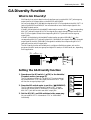
What is GA Diversity?
GA Diversity is an output select function that allows you to use the MIX OUT jacks as group
output jacks or AUX output jacks on the GA32/12 and GA24/12.
You can route either MIX (Variable) bus signals or MIX (Fix) bus signals to the MIX OUT 1–4
jacks of the GA32/12 and GA24/12. You can select either one of these output signals in the
Variable/Fix select section.
If the M1–M4 switches in the Variable/Fix select section are set to FIX ( ), the corresponding
MIX OUT jacks will output MIX (FIX) bus signals. Since each channel’s output level for the
MIX (FIX) bus signals is fixed, the corresponding MIX OUT jacks will function as group
output jacks.
If the M1–M4 switches in the Variable/Fix select section are set to VARIABLE ( ), the
corresponding MIX OUT jacks will output MIX (VARIABLE) bus signals. Since each channel’s
output level for the MIX (VARIABLE) bus signals is variable, the corresponding MIX OUT
jacks will function as AUX output jacks.
The GA Diversity function will enable you to configure a flexible bus system, such as four
groups and six AUX sends, two groups and eight AUX sends, or 10 AUX sends, etc., depending
on the application.
MIX
MIX
PFL
(FIX)
(VARIABLE)
1 2 3 4 1 2 3 4 5 6 7 8 9 10 L R CTL
FIX
3-Stage EQ
TO ST PAN
LOW
f
MID
HIGH
MIX
INSERT
I/O 1
MIX
ST
OUT 1 L R
EQ
g
VARIABLE/FIX
AFL
to AFL
to MTRX
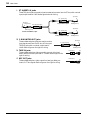
Setting the GA Diversity function
1. Press down the M1 switch (
FIX) in the Variable/
Fix select section (see page 6).
The FIX indicator will light up. The MIX OUT 1 output channel
will receive the MIX (FIX) 1 bus signal, and the MIX OUT 1 jack
will function as a group output jack.
2. Press the M1 switch again to set it to (
VARIABLE).
The FIX indicator will be turned off. The MIX OUT 1 output
channel will receive the MIX (VARIABLE) 1 bus signal, and the
MIX OUT 1 jack will function as an AUX output jack.
VARIABLE /
FIX
M1
FIX
M2
FIX
M3
FIX
M4
FIX
3. Set the M2, M3, and M4 switches in the same way.
You can set MIX OUT 1–4 channels to “FIX” or “VARIABLE”
individually.
GA32/12, GA24/12—Owner’s Manual
20
Specifications
Specifications
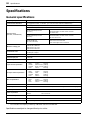
General specifications
Frequency response
20 Hz–20 kHz +1 dB, –2 dB, +4 dB 600Ω (ST1 OUT, ST2 OUT, MIX OUT, MATRIX OUT)
Total harmonic distortion
<0.1% @20 Hz–20 kHz, +14 dB 600Ω (ST1 OUT, ST2 OUT, MIX OUT, MATRIX OUT)
–128 dB equivalent input noise
–95 dB residual output noise (ST1 OUT, ST2 OUT, MIX OUT, MATRIX OUT)
Hum and noise
(Rs=150Ω, 20 Hz–20 kHz)
–83 dB residual output noise
(ST1 OUT)
ST master fader at nominal level.
all channel fader, mix level control: minimum
ST switch: OFF
–78 dB residual output noise
(MIX OUT)
Mix master fader at nominal level.
all channel fader, mix level control: minimum
M1–M4 switch: OFF
–64 dB (68 dB S/N)
(ST1 OUT, MIX OUT)
ST master/mix master fader, one channel fader and mix
level control at nominal level.
one channel gain control: maximum
Maximum voltage gain
84 dB CH IN to ST1 OUT
84 dB CH IN to MIX OUT
58 dB ST IN to ST1 OUT
58 dB ST IN to MIX OUT
Crosstalk at 1 kHz
–70 dB adjacent input
–70 dB input to output
Gain control
44 dB variable
Channel input pad
0 dB/26 dB
Channel input HPF
80 Hz 12 dB/oct
Input channel equalization
±15 dB Maximum
HIGH
10 kHz *
HI-MID
400 Hz–8 kHz
LO-MID
80 Hz–1.6 kHz
LOW
100 Hz *
shelving
peaking
peaking
shelving
ST input channel equalization
±15 dB Maximum
HIGH
10 kHz *
HI-MID
3 kHz
LO-MID
800 Hz
LOW
100 Hz *
shelving
peaking
peaking
shelving
Mix out equalization
±15 dB Maximum
HIGH
10 kHz *
shelving
MID
300 Hz–6 kHz peaking
LOW
100 Hz *
shelving
Meters
13 points LED x 14
Channel peak indicators
An indicator for each channel turns on when the pre-channel fader signal is –3 dB below clipping.
Phantom power
+48V (balanced)
Power requirement
USA and Canadian
General
Power consumption
120 W
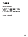
Dimensions (WxHxD)
GA32/12: 1372 x 161 x 705 mm GA24/12: 1144 x 161 x 705 mm
Weight
GA32/12: 38 kg GA24/12: 34 kg
*
120 V AC 60 Hz
230 V AC 50 Hz
Turn over/Roll off frequency of shelving: 3 dB below maximum variable level.
Specifications are subject to change without prior notice.
GA32/12, GA24/12—Owner’s Manual
Input specifications
21
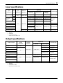
Input specifications
Input level
Input
connectors
Gain
trim
CH INPUT
1–12, 17–24/32
MAX
CH INPUT
13–16
Input
impedance
Nominal
impedance
3 kΩ
50-600Ω Mics
Connector type
Sensitivity1
Nominal level
Max. before
clipping
–86 dB (38.8 µV)
–60 dB (775 µV)
–40 dB (7.75 mV)
MIN
–42 dB (6.16 mV)
–16 dB (123 mV)
+4 dB (1.23 V)
MAX
–60 dB (775 µV)
–34 dB (15.5 mV)
–14 dB (155 mV)
MIN
–16 dB (123 mV)
+10 dB (2.45 V)
+30 dB (24.5 V)
–12 dB (195 mV)
+4 dB (1.23 V)
+20 dB (7.75 V)
AUX RETURN
TAPE IN
–26 dBV (50.1mV) –10 dBV (316 mV)
600Ω Line
A: XLR-3-31 type2
B: Phone jack2
Phone jack
(TRS)3
+8 dBV (2.51 V)
Phono
0 dB (775 mV)
+20 dB (7.75 V)
Phone jack, TRS4
–50 dB (2.45 mV)
–24 dB (48.9 mV)
10 kΩ
CH INSERT I/O
–26 dB (38.8 mV)
ST INSERT I/O
–10 dB (245 mV)
MIX INSERT I/O
TALKBACK INPUT
1.
2.
3.
4.
•
50-600Ω Mics
–66 dB (338 µV)
XLR-3-31 type3
Sensitivity is the lowest level that will produce an output of +4 dB (1.23 V) or the nominal output level when the unit is set to maximum gain.
Balanced
Unbalanced
T: OUT, R: IN, S: GND
0 dB=0.775 Vrms, 0 dBV=1 Vrms
Output specifications
Output connector
ST1 OUT
Output
impedance
Nominal
impedance
Output level
Connector type
Nominal
150Ω
ST2 OUT
600Ω Lines
MIX OUT
+4 dB (1.23 V)
Max. before clipping
+24 dB (12.3 V)
XLR-3-32 type1
+20 dB (7.75 V)
Phone jack2
+24 dB (12.3 V)
XLR-3-32 type1
+20 dB (7.75 V)
Phone jack2
75Ω
MATRIX OUT
C-R MONITOR OUT
REC OUT
–10 dBV (316 mV)
+10 dBV (3.16 V)
0 dB (775 mV)
+20 dB (7.75 V)
3 mW
100 mW
Phono
CH INSERT I/O
600Ω
10 kΩ Lines
ST INSERT I/O
Phone jack, TRS3
MIX INSERT I/O
PHONES
1.
2.
3.
•
100Ω
40Ω Phones
ST phone jack
Balanced
Unbalanced
T: OUT, R: IN, S: GND
0 dB=0.775 Vrms, 0 dBV=1 Vrms
GA32/12, GA24/12—Owner’s Manual
22
Specifications
Dimensions
GA32/12
500
500
186
186
W: 1372
GA24/12
172
800
172
W: 1144
Unit: mm
GA32/12, GA24/12—Owner’s Manual
D: 705
400
107
H: 161
–60
–50
–40
–30
–20
–10
0
+10
14/13,
16/15
Ch1-12, 17-24/32
PAD Off, GAIN Max
HPF
HPF
Ch13-16, GAIN Max
Ch1-12, 17-24/32
PAD On, GAIN Max
Ch1-12, 17-24/32
PAD Off, GAIN Min
80
INSERT I/O
HPF
Ch13-16, GAIN Min
HA
HA
PAD
PAD
GAIN
26dB
Ch1-12, 17-24/32
PAD On, GAIN Min
14R,
16R
13L(MONO),
15L(MONO)
1-12,
17-24/17-32
INPUT B
HA
PAD
Ch INSERT
4-Stage EQ
f
1R,
2R
1L(MONO),
2L(MONO)
4-Stage EQ
EQ
HA
Talkback INPUT
AUX RETURN
INPUT
3R,
4R
3L(MONO),
4L(MONO)
AUX RETURN
ø
4-Stage EQ
EQ
INPUT A
GAIN
f
PEAK
LEVEL
PEAK
+48V
80
HIGH
HIGH
ON
PFL
ON
PFL
ON
PFL
ON
PFL
ON
M3
M4
ON
ON
M10
M9
M8
M7
BAL
ST
M5-M10
M1-M4
ST
M10
M9
M8
M7
M6
M5
ST
M4
M3
M2
M1
ST
M10
PRE M9
M8
PRE M7
M6
PRE M5
M4
M3
ON
ON
M2
M1
ON
ON
ST PAN
PRE
PRE
M6
M5
M2
ON
PRE
M1
ON
MIX(VARIABLE) 1-10
MIX(FIX) 1-4
MIX
MIX
PFL
(FIX)
(VARIABLE)
1 2 3 4 1 2 3 4 5 6 7 8 9 10 L R CTL
MIX INSERT I/O
MIX
INSERT
I/O 1
VARIABLE/FIX
FIX
3-Stage EQ
EQ
3-Stage EQ
TAPE
IN
R
L
MIX
ST
OUT 1 L R
to AFL
MIX
OUT 5
to AFL
MIX OUT
ON ST
AFL
TAPE IN
MIX OUT 6-10: Same as MIX OUT 5
EQ
AFL
TO ST PAN
to MTRX
MIX OUT 2-4: Same as MIX OUT 1
HIGH
HIGH
HI-MID g
HI-MID
f
f
LOW
LOW
g
MID
g
MID
LO-MID g
LO-MID
LOW
LOW
PHANTOM
4
3
from 1
MIX OUT
2
ST INSERT I/O
ST
INSERT
I/O R
ST
INSERT
I/O L
ST1 OUT
from AFL
R
L
M4
M3
M2
M1
POST
ST1
AFL
PFL
LEVEL
PFL/AFL
TAPE IN
ON
MONO LEVEL
9
10
LEVEL
REC OUT
ST2 OUT
LEVEL
ON
AFL
LR
R
L
PHONES
–60
–50
–40
–30
–20
–10
0
+10
PHONES
C-R
MONITOR
OUT
MATRIX
OUT
1,2
to
C-R
MONITOR
C-R MONITOR
PFL•AFL/TAPE
MATRIX
from MTRX
12
to Meter
AFL
from MIX OUT
5
6
1
2
3
4
ST2
OUT
ST1
OUT
REC
OUT
from MIX OUT
R
L
R
L
R
L
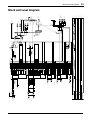
Block and Level diagram
23
Block and Level diagram
GA32/12, GA24/12—Owner’s Manual
VZ46530 R0 1 IP 28
98 01 1500 NP Printed in Taiwan
YAMAHA CORPORATION
P.O.Box 1, Hamamatsu, Japan