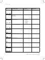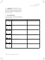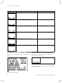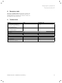
1
For the operator/expert technician
Operating and Installation Manual
auroMATIC 560
Solar Differential Controller
GB
VRS 560
For the operator/expert technician
Operating manual
auroMATIC 560
VRS 560
Solar Differential Controller
Contents
General information ................................................... 3
Special product features .......................................... 3
1
1.1
1.2
1.3
1.4
Notes on the documentation......................... 3
Storage of documents ...........................................3
Symbols used ...........................................................3
Validity of manual ...................................................3
CE label ......................................................................3
2
Safety ............................................................... 3
3
3.1
3.2
3.3
3.4
3.5
Information on installationand operation ....4
Vaillant warranty ..................................................4
Intended use .............................................................4
Requirements of the installation site ................4
Care ............................................................................4
Recycling and disposal ..........................................4
4
4.1
4.2
4.3
4.4
4.5
4.6
4.7
4.8
4.9
4.9.1
Functions ......................................................... 5
Solar yield .................................................................5
Reheating ..................................................................5
Reheating delay .......................................................5
Anti-legionella function .........................................5
Pump blocking protection .....................................5
Circulation .................................................................5
Calendar ....................................................................5
Activation duration controlling ...........................5
Special functions .....................................................6
Advance .....................................................................6
4.9.2
4.9.3
4.10
4.11
4.12
4.13
One-time reheating.................................................6
Holiday function ......................................................6
Cylinder priority ......................................................6
Frost protection function .....................................6
Solar circuit protection function .........................6
Solar pump kick (tube collector function) ........6
5
5.1
5.2
5.3
5.4
5.4.1
5.4.2
5.4.3
5.4.4
5.4.5
5.4.6
5.5
5.5.1
5.5.2
5.5.3
Operation ......................................................... 7
Operator guidance ..................................................7
Overview of controls ..............................................7
Overview of display ................................................7
Display types ............................................................8
Display, main operating level ...............................8
Display, info level ....................................................8
Display, programming level ..................................8
Display, special functions ......................................8
Display, service/diagnostics level .......................9
Display, installer level ............................................9
Settings......................................................................9
Calling up settings and operating values..........9
Settings at main operating level .........................9
Setting the reheating function timer
program ................................................................... 10
5.5.4 Setting the timer program, circulation
pump...........................................................................11
5.6
Activating the special functions ..........................11
6
Error messages ...............................................11
Notes on the documentation 1
Safety 2
General information
The auroMATIC 560 solar controller is a temperaturecontrolled differential controller set for solar hot water
generation with a demand-oriented reheating function
for Vaillant boilers.
The control set is a fully-equipped system for controlling solar systems with a collector field and a solar cylinder.
The controller can also be used in conjunction with various other components such as:
– A swimming pool heating system or
– A second solar cylinder
As well as:
– A second collector field
– A circulation pump
– A solid-fuel boiler
If a second collector field is connected, an additional
collector sensor (available as an accessory) must be installed.
If a second solar cylinder or a swimming pool are added
of the system, additional standard sensors (available as
accessories) must be installed.
It is possible to determine the solar yield by using an additional yield sensor (available as an accessory).
Special product features
The vrDIALOG 810 diagnostic software enables the simple display and query of specific parameters using a PC,
and can be obtained from Vaillant as an accessory. For
this purpose, the solar controller is equipped with an
eBUS interface.
1.2
Symbols used
Please observe the safety instructions in this operating
manual for the operation of the appliance!
d Danger!
Immediate risk of serious injury or death!
e Danger!
Risk of fatal electric shock!
H Danger!
Danger of burning and scalding!
a Caution!
Potentially dangerous situations for the product and environment!
h Note
Useful information and tips.
• Symbol for a required task.
1.3
Validity of manual
This operating manual applies exclusively for units with
the following article numbers: 306764, 306767.
For the article number of your unit, refer to the identification plate.
1.4
CE label
CE label indicates that the auroMATIC 560 solar differential controller complies with the basic requirements of
the applicable directives in accordance with the type
summary.
2
1
Notes on the documentation
The following information is intended to help you
throughout the entire documentation.
Further documents apply in combination with this operating and installation manual.
We accept no liability for any damage caused by failure to observe these instructions.
Other applicable documents
When operating the auroMATIC 560 solar differential
controller, please observe all operating manuals for the
components in the system. These operating manuals are
enclosed with the relevant system parts and additional
components.
Safety
The controller must be installed by a qualified engineer,
who is responsible for adhering to the existing standards and regulations.
Alterations
For alterations to the appliance or to its environment,
you must refer to the recognised handicraft business
which is responsible for it.
a Caution!
Risk of damage due to improper alterations!
Under no circumstances should you ever attempt to make alterations to the control set or
other parts of the system.
1.1
Storage of documents
Please store this operating and installation manual and
all other applicable documents in a safe place in case
they are needed for future reference.
If you move out or sell the appliance, please give the
documents to the new owner.
Operating manual – auroMATIC 560 0020008427_01
3
3 Information on installation and operation
3
Information on installation
and operation
3.1
Vaillant warranty
We only grant a Vaillant manufacturers warranty if a
suitably qualified engineer has installed the system in
accordance with Vaillant instructions. The system owner
will be granted a warranty in accordance with the
Vaillant terms and conditions. All requests for
work during the guarantee period must be made to
Vaillant Service Solutions (0870 6060 777).
3.2
Intended use
The auroMATIC 560 solar controller is a state-of-the-art
appliance which has been constructed in accordance
with recognised safety regulations. Nevertheless, improper use can cause serious or fatal injury to the user
or others, and the appliance or other property can be
damaged.
The unit is a control system for domestic hot water cylinders with solar heating, and includes a reheating option via a boiler or electrical heating rod.
Any other use or extended use is considered to be improper. The manufacturer or supplier is not liable for
any resulting damage. The user alone bears any risk.
Intended use includes the observance of the operating
manual and all other applicable documents.
3.3
Requirements of the installation site
The controller must be installed in a dry room.
3.4
Care
You can clean the casing of the controller with a damp
cloth and a little soap.
h Note
Do not use abrasive cleaners or detergents that
could cause damage, especially to the display.
3.5
Recycling and disposal
Neither the controller or any of its accessories belong in
the household waste. Make sure the old appliance and
any existing accessories are disposed of properly.
Caution!
a Any
improper use is forbidden.
4
Operating manual – auroMATIC 560 0020008427_01
Functions 4
4
Functions
4.1
Solar yield
The solar controller works on the principle of differential temperature control system. The controller always
switches on the collector pump when the difference in
temperature (collector temperature - cylinder temperature) is greater than the programmed activation difference.
The controller switches off the collector pump when the
difference in temperature (collector temperature - cylinder temperature) is less than the programmed deactivation difference.
The expert technician sets the parameters to the installer level when the solar controller is installed.
The solar yield is determined from:
– The difference in temperature between the collector‘s
forward flow and return flow
– The flow value specified (during installation) at the
control valve of the flow rate limiter
– The running time of the collector pump
During installation the expert technician sets the flow
rate limiter and enters the flow rate into the solar controller at the installer level. The solar yield is calculated
by the solar controller. The total yield can be called up
and reset in the installer level.
4.2
Reheating
The reheating function allows the cylinder to heat up to
the required temperature during a set time window,
even if the solar yield is insufficient. In this case the
water can be reheated using an external heater or an
electrical heating rod. You can set up time windows for
reheating the solar cylinder (see Section 5.5.3 for details).
4.3
Reheating delay
The controller is equipped with a reheating delay function to prevent unnecessary reheating by an external
heater or an electrical heating rod. This function delays
reheating by up to 30 min. in case the collector pump is
running and the solar yield becomes available. If the collector pump remains off and/or the desired cylinder
temperature is not reached after the delay period, the
cylinder is reheated using the external heater or electrical heating rod.
The reheating delay function is activated in the installer
level.
4.4
Anti-legionella function
The anti-Legionnaire‘s disease protection function is designed to kill germs in the cylinder and pipelines.
When the function is activated, the cylinder, the corresponding hot water pipes and circulation pump (if installed) are brought to a temperature of at least 60 °C
once a week at a specific time on a specific day, or
every day.
Operating manual – auroMATIC 560 0020008427_01
In doing so, the cylinder temperature is raised to 71 °C
and the corresponding circulation pump is switched on
(if installed). The anti-legionella function is implemented
either via an external heater or electrical heating rod if
this is used for reheating. The anti-Legionnaire’s disease
protection function will stop once a temperature of at
least 68 °C has been maintained for a period of
30 minutes.
The anti-legionella function is activated by the expert
technician at installer level.
4.5
Pump blocking protection
If no pumping has occurred for 23 hours, all installed
pumps are switched on for roughly 3 seconds to prevent
the pumps from seizing.
4.6
Circulation
If you only have one collector field connected, a circulation pump can be connected to the controller. You can
specify up to three heating windows for the circulation
pump in the timer program (see Sec. 5.5.4). Set up the
time program so that the circulation pump only operates at times when you expect a supply of hot water demand will be needed. Otherwise the circulation pump
operates unnecessarily and inadvertently cools down
the cylinder.
4.7
Calendar
The controller is equipped with a calendar so that it can
automatically adjust for daylight-savings time. To activate it, simply enter the current date in the installer
level.
h Note
Please observe that in the event of a power
failure the controller only has a power reserve
of 30 minutes. After 30 minutes, the internal
clock stops and the calender will not automatically resume function once power has been restored. In this case the time and date will need
to be reset.
4.8
Activation duration controlling
Activation duration controlling serves to keep the solar
circuit at the activation value, and thus in operation, for
as long as possible. The pump is switched on and off in
periodical bursts depending on the difference between
the collector temperature and lower cylinder sensor.
When the activation difference is reached, the function
is started (if activated) with an activation duration of
30 % – i.e. the pump is switched on for 18 seconds and
then switched off for 42 seconds. If the difference in
temperature increases, the activation duration is prolonged (e.g. 45 seconds on, 15 seconds off). If the difference in temperature falls, the activation duration is reduced (e.g. 20 seconds on, 40 seconds off). The period
length is always a minute. Activation duration control is
activated in the installer level.
5
4 Functions
4.9
Special functions
Please refer to Sec. 5.6 for information on how to activate the following special functions.
4.9.1 Advance
When the advance is activated, the reheating function is
enabled. This means that the set target value for the
cylinder will be maintained by reheating if necessary.
4.9.2 One-time reheating
When this function is activated, the cylinder temperature is reheated to the set level one time.
4.9.3 Holiday function
When this function is activated, the operating mode is
switched to "OFF" for the set holiday period
(1 to 99 days). This deactivates both the solar yield and
the reheating function.
4.10
Cylinder priority
Two solar-charged cylinders can be connected to the
heating installation. You can use the PRIO cylinder priority function to define which cylinder should be
charged as the highest priority.
This is normally the drinking water cylinder. The cylinders can only be clearly identified via the cylinder sensors (cylinder 1 = Sp 2; cylinder 2 = SP 3).
You can only change this setting at the installer level.
The cylinder that has been assigned the highest priority
will always be charged if the collector temperature is
greater than the sum of the actual temperature in the
cylinder and the activation difference specified. The
heating of the cylinder will stop once the maximum temperature for the cylinder is reached, or if the collector
temperature is less than the actual cylinder temperature plus the set deactivation difference.
The second cylinder can only be heated when the first
cylinder is not being heated. The charging of the second
cylinder is interrupted for at least 5 minutes every
15 minutes to check whether the cylinder can be
charged with the highest priority. The same activation
and deactivation conditions apply here as well.
4.12
Solar circuit protection function
If the solar heat exceeds the current heat demand
(e.g. all cylinders fully charged), the temperature may
occur in the collector field may increase rapidly.
If the safety temperature at the collector sensor is exceeded, the collector pump is switched off to protect
the solar circuit (solar pump, valves, etc.) from overheating, or restarting is prevented if a solar reheating
requirement exists. The solar pump is switched back on
once the system has cooled down. This function is executed independently for each collector field.
4.13
Solar pump kick (tube collector function)
Depending on the design of the tube collectors, the
measured value obtained for the purposes of temperature recording may be subject to a time delay. This can
be reduced via the tube collector function.
Measured value of collector temperature with active
tube collector function:
The solar pump is switched on for 15 s (solar pump kick)
once the temperature at the collector sensor has risen
by 2 °C. The heated solar fluid is thereby transported
more quickly to the measuring point.
If the temperature difference between the collector and
cylinder temperature is at least 10 °C) the solar pump
runs for as long as is necessary to heat the cylinder up
(differential control). If two solar circuits are connected,
the tube collector function is activated for both solar
circuits.
The function is implemented separately in each case for
all collector fields.
4.11
Frost protection function
The frost protection function is relevant to Spain only
due to statutory regulations and is deactivated in the
as-delivered condition (standard setting: OFF).
h Note
This function should not be activated to prevent undesired cooling of the cylinder.
6
Operating manual – auroMATIC 560 0020008427_01
Operation 5
5
Operation
5.3
5.1
Operator guidance
The controller has a display which consists of symbols,
and is designed according to the Vaillant "turn and
click" operating concept. You can call up and set values
by turning the dial. You can also click the dial in order to
call up values within an operating level. You can access
the operating and display levels with the three selection
buttons.
To prevent operating errors, the programming button
must be held down for roughly three seconds to reach
the installer level.
5.2
Overview of controls
2
Key
1 Display
2 Dial (turn and click)
i Information button
F Special functions button
P Programming button
1
2
3
4
13
5
12
11
6
10
9
8
1
Fig. 5.1 Controls
Overview of display
7
Fig. 5.2 Display
Key
1 Programming level
2 Service/diagnostics level
3 Reheating
4 Info level
5 Programming of timer programs
6 Solar yield (flashes if solar yield is available)
7 Units
8 Cursor
9 Multi-function display
10 Weekdays
11 Target/actual value
12 Operating modes
13 Special functions
Display symbols
Timer programs:
Timer program for reheating function
Programming of timer program for connected circulation pump
Operating modes:
Reheating function with timer program
Reheating function in constant standby mode
No reheating
No actuation of solar pump(s),
no reheating
Special functions:
Party
One-time reheating
Holiday function
Operating manual – auroMATIC 560 0020008427_01
7
5 Operation
5.4
Display types
5.4.1 Display, main operating level
The main operating level appears when the appliance is
switched on. Please refer to Sec. 5.5.2 for information
on how to set and change the values.
5.4.3 Display, programming level
You can access the level for programming the controller‘s operating times by pressing the "P" programming
button. You can set timer programs here for reheating
the solar cylinder and for a connected circulation pump
(see Section 5.5.3 or 5.5.4).
The display returns to the main operating level if you
press the programming button.
6
5
4
3
1
2
7
6
1
2
5
4
Fig. 5.3 Display, main operating level
Key
1 Display, solar yield present
2 Actual collector temperature
3 Actual time or LEG for anti-legionella function (if active);
FROS for frost protection function;
PROT for solar circuit protection function
4 Current day of the week
5 Current temperature of cylinder (the target temperature can
be called up and adjusted by turning the dial)
6 Current operating mode
5.4.2 Display, info level
You can access the info level by pressing the info button. The display initially appears as seen in the diagram
below. You can call up additional information by pressing the info button again (see Sec. 5.5.1). The information called up appears on the display for roughly five
seconds, then the display returns to the main operating
level.
1
4
2
3
3
Fig. 5.5 Display, programming level
Key
1 Programming level
2 Timer program for solar cylinder reheating
(water tap symbol) or circulation pump
(pump symbol)
3 End time
4 Start time
5 Day of the week or block of days
6 Cursor (marks the value to be changed)
7 Time window
5.4.4 Display, special functions
By pressing the "F" button, you can access the special
functions: party, one-time reheating, and holiday function. After roughly ten seconds, the selected function is
activated and the display returns to the main operating
level.
Please refer to Sec. 5.6 for information on how to activate the individual special functions.
3
2
1
Fig. 5.4 Display, info level
Key
1 Info level
2 Display, solar yield
3 Yield in kWh
4 Set target temperature of cylinder
8
Fig. 5.6 Display, special functions
Key
1 Special function activated
2 Cursor (marks the special function selected)
3 Symbol for the special function selected
Operating manual – auroMATIC 560 0020008427_01
Operation 5
5.4.5 Display, service/diagnostics level
The actuators and sensors should be checked by the
technician expert.
You can access the service/diagnostics level by simultaneously pressing the programming button "P" and the
dial for roughly 3 seconds. All actuators and sensors can
be controlled and checked in this level (see Chapter 7 in
the installation instructions).
The display returns to the main operating level if you
press the programming button.
5.4.6 Display, installer level
The parameters at installer level should only be adjusted by an expert technician.
You can access the installer level by pressing the programming button "P" for at least 3 seconds.
Press the programming button briefly to return to the
basic display.
5.5
Settings
Settings
Collector sensor 1 temperature
Collector sensor 2 temperature
(if connected)
Operating hours, solar pump 1
Operating hours, solar pump 2
5.5.1 Calling up settings and operating values
You can call up the values set at the info level successively by pressing the info button repeatedly.
Once called up, the information remains in the display
for roughly five seconds then the display returns to the
main operating level.
Display
Display
Settings
Cylinder temperature target value
Yield
The current date is only displayed in the
following cases
- a valid date is entered during start-up
and
- the calendar has been activated.
Timer program for heating window
Cylinder sensor 1 temperature
Table 5.1 Values for settings (continued)
Cylinder sensor 2 temperature
Cylinder sensor 3 temperature
(if connected)
Table 5.1 Values for settings
Operating manual – auroMATIC 560 0020008427_01
Further displays will be shown here depending on how
many timer programs you have set (see Sections 5.5.3
and 5.5.4).
5.5.2 Settings at main operating level
You can adjust the following settings in the main operating level:
– Cylinder temperature target value,
– Operating mode,
– Current day of the week,
– Current time
When you call up a setting, it can be viewed and/or
changed for roughly five seconds before the basic display at the main operating level reappears automatically. Click the dial within the five second period to display
the next setting.
9
5 Operation
Time window
Weekday/
Block of days
Start time
End time
Reheating function with timer program
H1
H2
H3
M0 - S0
—
—
5:30
—
—
22:00
—
—
Reheating function in constant standby
mode
Table 5.3 Default reheating program
Operating modes:
No reheating
No actuation of solar pump(s),
no reheating
Reheating function in automatic mode – the
corresponding symbol for the time window
status is displayed next to the clock symbol.
Time window active
There are four steps to setting the times you want:
1. Select the time window,
2. Select a weekday or block of days,
3. Specify the start time,
4. Specify the end time.
You can specify up to three time windows, as long as
none of the time windows overlap another.
For clarification, the individual steps are shown in the
following table:
Display
Required steps
Press the programming key P
Turn the dial until you see the tap symbol.
Reheating function in automatic mode
Time window not active
Display
Required steps
Turn the dial, after 3 seconds the cursor
marks the temperature display, which
will be flashing.
Click the dial - The cursor marks the
changeable value (H1), which also flashes.
Select the time window by turning the
dial.
Settings: H 1, H 2, H 3
Turn the dial to adjust the target value
for the cylinder temperature.
Click the dial - The cursor will mark the
operating modes. The selected operating
mode flashes.
Click the dial - The cursor marks the
block of days display, which also flashes.
Select a block of days or a single day of
the week by turning the dial.
Settings: (MO-SU); (MO - FR); (SA-SU);
(MO); (TU); (WE); (TH); (FR); (SA); (SU)
Select an operating mode by turning the
dial.
Click the dial - The cursor will mark the
day of the week. The selected day of the
week flashes.
Click the dial – The cursor marks the
start time and the hour display flashes.
Select the start time by turning the dial.
Click the dial again to set the minutes.
Turn the dial to select the current day of
the week.
Click the dial - The cursor will mark the
hours and/or the minutes.
Turn the dial to adjust the current time.
Click the dial – The cursor marks the end
time and the hour display flashes.
Select an end time by turning the dial.
To adjust the minutes, click the dial
again.
Table 5.4 Setting time windows
Table 5.2. Settings in the main operating level
5.5.3 Setting the reheating function timer program
You can create a timer program with up to three time
windows for reheating the solar cylinder.
The controller is equipped with a default program which
can be customised to meet your individual needs.
10
Operating manual – auroMATIC 560 0020008427_01
Operation 5
Error messages 6
5.5.4 Setting the timer program, circulation pump
You can create a customised timer program for a connected circulation pump (only possible for hydraulic
plan 1), just as you can for the reheating function.
The controller is equipped with a default program for
this as well:
Time window
Weekday/
Block of days
Start time
End time
H1
H2
H3
M0 - S0
—
—
6:00
—
—
22:00
—
—
Table 5.5 Default circulation pump program
You can access the timer program for the circulation
pump by pressing programming button "P" and turning
the dial until the pump symbol appears in the display instead of the water tap symbol. The setting of the desired heating times is done in the same manner as the
setting of the heating times for the reheating function
(see Sec. 5.5.3). Set up the timer program so that the
circulation pump only operates at times when you expect a supply of hot water will be needed. Otherwise the
circulation pump operates unnecessarily and inadvertently cools down the cylinder.
5.6
Display
6
Error messages
The auroMATIC 560 solar controller shows error messages in the main operating level if there is a problem
with the temperature sensor.
The sensor configuration will always be displayed when
the controller is switched on for the first time, or if the
power supply has been switched off and on again. Depending on the set hydraulic plan, the controller recognises whether there is an error, or if the sensor is not
necessary for operation.
a Caution!
Never try to repair or carry out maintenance
work on the controller yourself. Call in an approved technician. We recommend concluding a
maintenance contract for your solar system
with a recognised handicraft business.
The following table explains the error messages.
Display
Message/Description
Error cylinder sensor 1
This error occurs if the there is a problem with the connected sensor.
Activating the special functions
Required steps
Advance
Press the special function button oncethe party symbol flashes for approx. ten
seconds in the display, then the function
is activated. The function is deactivated
automatically when the next reheating
window begins.
If you want to deactivate the function
before, simply reselect the function.
The function can only be activated in the
reheating operation mode .
One-time reheating
Press the special function button twice The one-time reheating symbol flashes in
the display for approx. ten seconds, then
the function is activated.
If you want to deactivate the function
before, simply reselect the function.
Holiday function
Press the special function button three
times - the holiday function symbol flashes in the display for approx. ten seconds,
and you can use the dial to set the
number of holidays. Finally, the function
is activated for the set time.
If you want to deactivate the function
before, simply reselect the function.
If the anti-Legionnaire’s disease function
is activated, the protection will be carried out on the last holiday.
Error cylinder sensor 2
This error occurs if the there is a problem with the sensor, or if it is not connected.
Error cylinder sensor 3
This error occurs if the there is a problem with the connected sensor.
Table 6.1 Error messages
No error messages are output for collector sensors Kol 1
and Kol 2. A plausibility check is still possible, e.g. by
comparing the collector temperature with the outside
temperature.
Table 5.6 Activating the special functions
Operating manual – auroMATIC 560 0020008427_01
11
For the operator/expert technician
Installation Manual
auroMATIC 560
VRS 560
Solar Differential Controller
Contents
1
1.1
1.2
1.3
Notes on the documentation.........................2
Storage of documents ...........................................2
Symbols used ...........................................................2
Validity of manual ...................................................2
6
6.1
6.2
Start-up......................................................... 20
Setting system parameters ............................... 20
Resetting the system parameters to the
default setting........................................................23
2
2.1
2.2
Description of the unit ...................................2
CE label ......................................................................2
Intended use .............................................................2
7
Service/diagnostics ......................................23
8
Emergency mode.......................................... 25
3
3.1
3.2
Safety instructions and regulations ............ 3
Safety instructions .................................................3
Regulations ...............................................................3
9
Technical data .............................................. 25
10
Sensor characteristics ................................ 26
4
4.1
4.2
4.3
4.3.1
4.3.2
4.4
Assembly ......................................................... 3
Scope of delivery ....................................................3
Assembly of VR 10 standard sensor ..................3
Accessories ...............................................................3
VR 10 standard sensor ...........................................3
VR 11 collector sensor ............................................3
Installing the controller housing .........................4
11
Vaillant Service ............................................ 26
5
5.1
5.2
5.3
5.4
Electrical installation .....................................4
Wiring according to hydraulic plan.....................5
Hydraulic plan 1........................................................6
Hydraulic plan 2......................................................12
Hydraulic plan 3..................................................... 16
1 Notes on the documentation
2 Description of the unit
1
Notes on the documentation
The following information is intended to help you
throughout the entire documentation.
Further documents apply in combination with this operating and installation manual.
We accept no liability for any damage caused by failure to observe this manual.
a
Caution!
This document is not a manual for making hydraulic connections. The appropriate documents
should be referred to for this.
Other applicable documents
For the expert technician:
– This operating and installation manual
– Operating, assembly, and installation instructions for
the additional components
1.1
Storage of documents
Please give this operating and installation manual and
all other applicable documents and auxiliary equipment
to the owner of the system. The owner shall ensure that
the manuals and auxiliary equipment are properly
stored, so that they are available whenever required.
1.2
Symbols used
Please observe the safety instructions in this installation
instructions when installing the appliance!
2
Description of the unit
2.1
CE label
The CE label indicates that the controller meets the
basic requirements of the Council of Europe‘s directive
89/336/EEC for electromagnetic compatibility.
2.2
Intended use
The auroMATIC 560 controller is a state-of-the-art appliance which has been constructed in accordance with
recognised safety regulations. Nevertheless, improper
use can cause serious or fatal injury to the user or others, and the appliance or other property can be damaged.
The unit is a control system for domestic hot water cylinders with solar heating, and includes a reheating option via a boiler or electrical heating rod.
Any other use or extended use is considered to be improper. The manufacturer or supplier is not liable for
any resulting damage. The user alone bears any risk.
Intended use includes the observance of the operating
and installation manuals, and all other applicable documents.
Caution!
a Any
improper use is forbidden.
Danger!
d Immediate
risk of serious injury or death!
Danger!
e Risk
of fatal electric shock!
Danger!
H Danger
of burning and scalding!
Caution!
a Potentially
dangerous situations for the product and environment!
h Note
Useful information and tips.
• Symbol for a required task.
1.3
Validity of manual
These installation instructions apply exclusively for units
with the following article numbers: 306764, 306767.
For the article number of your unit, refer to the identification plate.
2
Installation instructions – auroMATIC 560 0020008427_01
Safety instructions and regulations 3
Assembly 4
3
Safety instructions and regulations
3.1
Safety instructions
The controller must be installed by a qualified engineer,
who is responsible for adhering to the existing standards and regulations. We accept no liability for any damage caused by failure to observe these instructions.
e
Danger!
Risk of fatal electric shock from touching live
connections.
Before working on the unit, switch off the
power supply and secure against restart. Only
remove the controller from the wall installation
or it pull out of the plinth once the power supply has been switched off.
3.2
Regulations
All wiring must be in accordance with Building Regulations Part P and BS 7671 (IEE Wiring Regulations), and
must be carried out by a suitably qualified person.
Use standard wires for wiring.
Minimum cross-section of wires:
– Power supply 230 V
(pump connection cable):
1.5 mm2
– Extra-low voltage lines
(sensor wires):
0.75 mm2
4
Assembly
4.1
Scope of delivery
Using Table 4.1, verify the scope of delivery for the controller set.
Item
Quantity Components
1
1
auroMATIC 560 controller
2
1
VR 11 collector sensor
3
3
VR 10 standard sensor
4
1
C1/C2 cable
Table 4.1 Scope of delivery
4.2
Assembly of VR 10 standard sensor
The VR 10 standard sensor is designed so that it can be
used as an immersion sensor or surface mount sensor.
When used as a surface mount sensor, the sensor is secured to the forward flow pipe or the return pipe using
the supplied tension band. In order to guarantee good
heat transfer, the sensor is flat on one side. We also recommend that the pipe with the sensor is insulated, in
order to enable the best possible measuring of temperature.
Connections with 230 V and sensor wires must be laid
separately if longer than 10 m.
230 V connection leads must be supplied in 1.5 mm2 and
fastened to the wall installation using the accompanying
cable clamps.
Do not use free terminals on the appliances as support
terminals for other wiring.
The controller must be installed in a dry room.
H
Danger!
Danger of scalding due to hot water!
The temperature of the solar hot water storage
tank may sometimes be considerably higher
than 60 °C (due to the solar heating, but also
the anti-legionella function, if activated).
Have your expert technician install a mixer
valve with cold water supply without fail.
Have the mixer valve adjusted by your expert
technician.
Fig. 4.1 VR 10 standard sensor
4.3
Accessories
The following accessories are necessary in order to connect a second collector field or an additional solar cylinder to the controller, and to enable measurement of the
solar yield.
4.3.1 VR 10 standard sensor
The use of additional standard sensors is necessary if
you want to connect a second solar cylinder to the controller.
4.3.2 VR 11 collector sensor
If a second collector field is connected, it is necessary to
install a second collector sensor from the Vaillant accessory range.
Installation instructions – auroMATIC 560 0020008427_01
3
4 Assembly
5 Electrical installation
4.4
Installing the controller housing
The controller is designed to be mounted on a wall and
is equipped with System ProE terminal strips. These terminals must be used for all connections made at the installation site.
ProE-system wiring
230 V~
PE N L
KOL1-P
PE N L
KOL2-P/ZP
PE N L
LEG/BYP
PE N L
EP
2 1
LP/UV1
PE N L
C1/C2
C1 C2
KOL1
2 1
SP1
2 1
SP2
2 1
SP3
2 1
Ertrag
2 1
KOL2
2 1
3
Fig. 4.4 Fold-up the control panel
• Fold the control panel towards the top.
• Wire the controller according to the selected hydraulic
plan (see Section 5.1).
• Secure all cables with the accompanying cable clamps
(3).
• Fold the control panel back down.
• Attach the front cover again.
5
Electrical installation
The electrical connection may only be carried out by an
approved specialist company.
Danger!
e Risk
of fatal electric shock from touching live
Fig. 4.2 Opening the controller housing
The cover consists of two parts, which can be removed
separately.
• As shown in Fig. 4.2, pull the lower front cover off of
the controller housing.
1
230 V~
PE N L
KOL1-P
PE N L
KOL2-P/ZP
PE N L
LEG/BYP
PE N L
EP
2 1
LP/UV1
PE N L
C1/C2
C1 C2
KOL1
2 1
SP1
2 1
SP2
2 1
SP3
2 1
Ertrag
2 1
KOL2
2 1
2
connections. Before working on the appliance,
turn off the power supply and secure against
restart.
Caution!
a The
circuit board can be damaged if short
circuited through the connection leads. For
safety purposes, a max. of 30 mm of insulation
may be removed from the ends of 230 V leads
which will be connected to ProE plugs. If more
insulation is removed, there is a risk of short
circuiting the circuit board.
Caution!
When exchanging the controller in an existing
system, sensor-curve characteristics should be
taken into consideration (see Sec. 11), and the
sensors should be replaced if necessary!
Fig. 4.3 Fastening the controller housing
• Mark the position of both holes (1 and 2) and drill the
bore holes.
• Select the wall plugs to suit the state of the wall, and
screw the controller housing on tightly.
4
Installation instructions – auroMATIC 560 0020008427_01
Electrical installation 5
Caution!
a An
optional electrical heating rod (EP) must be
installed with an additional relay or contactor
with a circuit-breaking capacity of at least
16 A. Never operate an electrical heating rod in
connection with the auroMATIC 560 without an
additional external relay or contactor.
Caution!
The C1/C2 contact is a 24 V low-voltage contact and should never be used as a 230 V
switching contact.
5.1
Wiring according to hydraulic plan
To simplify installation, three hydraulic plans are stored
in the controller. The relevant plan must be selected according to the system configuration used.
Each of the hydraulic plans show a possible system configuration in which some system components are optional.
Caution!
a These
hydraulic plans are only schematic rep-
resentations and cannot be used for the preparation of the hydraulic piping.
Hydraulic
plan
1
Bivalent cylinder
Monovalent
cylinder
X
X
Number of
collectors
Circulation
pump
connected
Solid-fuel boiler
connected
Integration of
second cylinder
or swimming
pool
1
yes
no
yes
1
no
no
yes
2
X
2
no
no
yes
3
X
1
no
yes
yes
Table 5.1 System configuration
Installation instructions – auroMATIC 560 0020008427_01
5
5 Electrical installation
5.2
Hydraulic plan 1
I
II
III
VRS 560
C1/C2
C1/C2
LEG/BYP
Kol1
(VR 11)
C1/C2
C1/C2
230 V
230 V ~
HZ-K
230 V ~
HZ-K
HZ-K
S
Kol1-P
1
Sp1
(VR 10)
ZP
Ertrag
(VR 10)
Sp2
(VR 10)
LEG/BYP
EP
Fig. 5.1 Hydraulic plan 1 with system configuration: one collector field, one solar cylinder, connection option for various heaters for reheating the cylinder
Designation in Components
hydraulic plan/
wiring diagram
Designation in Components
hydraulic plan/
wiring diagram
I, II, III
Connection option for various heaters for reheating the cylinder
S
Control of contactor for optional electrical
heating rod
C1/C2
Connections for controlling the heater used for
reheating the cylinder
1
Mixer valve
HZ-K
Heating circuit(s)
KW
Cold water
ZP
Circulation pump
EP
Electrical heating rod (optional)
Kol1-P
Solar circuit pump 1
Kol1
Collector sensor 1
Yield
LEG/BYP
Sp1
Sensor for measuring yield (optional)
Legionella protection pump or electric heater
cartridge
Cylinder sensor 1
Sp2
Cylinder sensor 2
230 V
230 V main power connection
F1 (T4)
Fuse holder
VC/VK
Heater wiring area
Table 5.2 Legend for Fig. 5.1 and Fig. 5.2 (continued)
Danger!
H Danger
of scalding due to hot water.
The mixer valve must be installed without fail
to ensure protection against scalding.
Table 5.2 Key for Fig. 5.1 and Fig. 5.2
6
Installation instructions – auroMATIC 560 0020008427_01
Electrical installation 5
VC / VK
F1
T4
Kol1-P
Kol2-P / ZP
LEG/BYP
230 V~
230V Netz
EP
LP/UV 1
5 V / 24 V
VRS 560
C1/C2
Kol1
Sp1
Sp2
Sp3
Ertrag
Kol2
Fig. 5.2 Connection diagram for hydraulic plan 1
h Note
LEG/BYP can be used as a legionella protection
pump or an electric heater cartridge. Only one
of these options can be used.
Installation instructions – auroMATIC 560 0020008427_01
7
5 Electrical installation
Hydraulic plan 1: Connection of a second cylinder or
swimming pool
VRS 560
C1/C2
Kol1
(VR 11)
230 V ~
Hg
LEG/BYP
Kol1-P
Sp1
(VR 10)
3
ZP
S
Ertrag
(VR 10)
LEG/BYP
1
LP/UV1
Sp2
(VR 10)
EP
Sp3
(VR 10)
Sp3
2
A
400 V
Fig. 5.3 Hydraulic plan 1: Connection of a second cylinder or
swimming pool
Danger!
H Danger
of scalding due to hot water.
The mixer valve must be installed without fail
to ensure protection against scalding.
8
Installation instructions – auroMATIC 560 0020008427_01
Electrical installation 5
Designation in Components
hydraulic plan/
wiring diagram
Designation in Components
hydraulic plan/
wiring diagram
C1/C2
Connections for controlling the heater used for
reheating the cylinder
Yield
Sensor for measuring yield (optional)
LEG/BYP
Hg
Boiler
KW
Cold water
Sp1
Legionella protection pump or electric heater
cartridge
Cylinder sensor 1
ZP
Circulation pump
Sp2
Cylinder sensor 2
Sp3
Cylinder sensor 3
S
2
Control of contactor for optional electrical
heating rod
400 V connection, 3 phase
3
Mixer valve
EP
Electrical heating rod (optional)
SR
LP/UV 1
1
A
Swimming pool controller (provided by customer)
Diverter valve
LP/UV 1 diverter valve in de-energised state
Alternative connection for second cylinder
230 V
230 V main power connection
Kol1-P
Solar circuit pump 1
F1 (T4)
Fuse holder
Kol1
Collector sensor 1
VC/VK
Heater wiring area
Table 5.3 Key for Fig. 5.3 and Fig. 5.4
VC / VK
Table 5.3 Legend for Fig. 5.3 and Fig. 5.4 (continued)
F1
T4
Kol1-P
Kol2-P / ZP
LEG/BYP
230 V~
230V Netz
EP
LP/UV 1
5 V / 24 V
VRS 560
C1/C2
Kol1
Sp1
Sp2
Sp3
Ertrag
Kol2
Fig. 5.4 Connection diagram for hydraulic plan 1 Connection of
a second cylinder or swimming pool
h Note
LEG/BYP can be used as a legionella protection
pump or an electric heater cartridge. Only one
of these options can be used.
Installation instructions – auroMATIC 560 0020008427_01
9
5 Electrical installation
Hydraulic plan 1: integration into monovalent systems
The controller can also be used in conjunction with units
that heat water according to the principle of instantaneous heating. Integrate the controller according to the
following hydraulic plan.
VRS 560
Kol1
(VR 11)
230 V ~
VED ...
Kol1-P
Sp1
(VR 10)
1
Ertrag
(VR 10)
Sp2
(VR 10)
Fig. 5.5 Hydraulic plan 1: integration into monovalent systems
Designation in hydraulic plan/wiring
diagram
Components
VED...
Vaillant electric instantaneous heater
Kol1-P
Solar circuit pump 1
Kol1
Collector sensor 1
Sp1
Cylinder sensor 1
Sp2
Cylinder sensor 2
230 V
230 V main power connection
F 1 (T4)
Fuse holder
Yield
Sensor for measuring yield (optional)
1
Mixer valve
230 V
230 V main power connection
Danger!
H Danger
of scalding due to hot water.
The mixer valve must be installed without fail
to ensure protection against scalding.
Table 5.4 Key for Fig. 5.5 and Fig. 5.6
10
Installation instructions – auroMATIC 560 0020008427_01
Electrical installation 5
F1
T4
Kol1-P
Kol2-P / ZP
LEG/BYP
230 V~
230V Netz
EP
LP/UV 1
5 V / 24 V
VRS 560
C1/C2
Kol1
Sp1
Sp2
Sp3
Ertrag
Kol2
Fig. 5.6 Connection diagram for hydraulic plan 1: Integration of
auroMATIC 560 in monovalent systems
Danger!
H Danger
of overheating!
When integrating the controller, always install
a thermostatic mixer valve to limit the maximum temperature to prevent scalding and protect the unit. Depending on the boiler, set it at
60 °C (for example).
h Note
The VED E Solar monitors the inlet tempera-
ture independently and switches in the hot
water post-heating according to the temperature of the solar cylinder. An additional control
command is not required in this case.
Installation instructions – auroMATIC 560 0020008427_01
11
5 Electrical installation
5.3
Hydraulic plan 2
I
II
III
VRS 560
C1/C2
C1/C2
Kol2
(VR 11)
Kol1
(VR 11)
C1/C2
C1/C2
230 V
LEG/BYP
HZ-K
230 V ~
HZ-K
HZ-K
S
Kol1-P
Kol2-P
1
Sp1
(VR 10)
ZP
Ertrag
(VR 10)
Sp2
(VR 10)
LEG/BYP
EP
Fig. 5.7 Hydraulic plan 2 with system configuration: Two collector fields, one solar cylinder, connection option for
various heaters for reheating the cylinder
Designation in Components
hydraulic plan/
wiring diagram
I, II, III
Connection option for various heaters for reheating the cylinder
C1/C2
Connections for controlling the heater used for
reheating the cylinder
Designation in Components
hydraulic plan/
wiring diagram
S
Control of contactor for optional electrical
heating rod
1
Mixer valve
230 V
230 V main power connection
HZ-K
Heating circuit(s)
F1 (T4)
Fuse holder
EP
Electrical heating rod (optional)
VC/VK
Heater wiring area
Kol1-P
Solar circuit pump 1
Kol2-P
Solar circuit pump 2
Kol1
Collector sensor 1
Kol2
Collector sensor 2
Yield
Sensor for measuring yield (optional)
LEG/BYP
Sp1
Legionella protection pump or electric heater
cartridge
Cylinder sensor 1
Sp2
Cylinder sensor 2
Table 5.5 Legend for Fig. 5.7 and Fig. 5.8 (continued)
Danger!
H Danger
of scalding due to hot water.
The mixer valve must be installed without fail
to ensure protection against scalding.
Table 5.5 Key for Fig. 5.7 and Fig. 5.8
12
Installation instructions – auroMATIC 560 0020008427_01
Electrical installation 5
VC / VK
F1
T4
Kol1-P
Kol2-P / ZP
LEG/BYP
230 V~
230V Netz
EP
LP/UV 1
5 V / 24 V
VRS 560
C1/C2
Kol1
Sp1
Sp2
Sp3
Ertrag
Kol2
Fig. 5.8 Connection diagram for hydraulic plan 2
h Note
LEG/BYP can be used as a legionella protection
pump or an electric heater cartridge. Only one
of these options can be used.
Installation instructions – auroMATIC 560 0020008427_01
13
5 Electrical installation
Hydraulic plan 2: Connection of a second cylinder or
swimming pool
VRS 560
C1/C2
Kol1
(VR 11)
Kol2
(VR 11)
230 V ~
Hg
Kol1-P
LEG/BYP
Kol2-P
Sp1
(VR 10)
3
ZP
S
Ertrag
(VR 10)
LEG/BYP
1
LP/UV 1
Sp2
(VR 10)
EP
Sp3
(VR 10)
Sp 3
2
A
400 V
Fig. 5.9 Hydraulic plan 2: Connection of a second cylinder or
swimming pool
Danger!
H Danger
of scalding due to hot water.
The mixer valve must be installed without fail
to ensure protection against scalding.
14
Installation instructions – auroMATIC 560 0020008427_01
Electrical installation 5
Designation in Components
hydraulic plan/
wiring diagram
Designation in Components
hydraulic plan/
wiring diagram
C1/C2
Yield
Sensor for measuring yield (optional)
LEG/BYP
Connections for controlling the heater used for
reheating the cylinder
Hg
Boiler
EP
Electrical heating rod (optional)
Sp1
Legionella protection pump or electric heater
cartridge
Cylinder sensor 1
SR
Sp2
Cylinder sensor 2
LP/UV 1
Swimming pool controller (provided by customer)
Diverter valve
Sp3
Cylinder sensor 3
LP/UV 1 diverter valve in de-energised state
S
1
Alternative contactor or KI 3-4
(old or foreign boilers)
A
Alternative connection for second cylinder
2
400 V connection, 3 phase
Kol1-P
Solar circuit pump 1
3
Mixer valve
Kol2-P
Solar circuit pump 2
230 V
230 V main power connection
Kol1
Collector sensor 1
F1 (T4)
Fuse holder
Kol2
Collector sensor 2
VC/VK
Heater wiring area
Table 5.6 Key for Fig. 5.9 and Fig. 5.10
VC / VK
Table 5.6 Legend for Fig. 5.9 and Fig. 5.10 (continued)
F1
T4
Kol1-P
Kol2-P / ZP
LEG/BYP
230 V~
230V Netz
EP
LP/UV 1
5 V / 24 V
VRS 560
C1/C2
Kol1
Sp1
Sp2
Sp3
Ertrag
Kol2
Fig. 5.10 Connection diagram for hydraulic plan 2: Connection
of a second cylinder or swimming pool
h Note
LEG/BYP can be used as a legionella protection
pump or an electric heater cartridge. Only one
of these options can be used.
Installation instructions – auroMATIC 560 0020008427_01
15
5 Electrical installation
5.4
Hydraulic plan 3
I
VRS 560
II
III
C1/C2
C1/C2
C1/C2
C1/C2
230 V ~
Kol1
(VR 11)
230 V
230 V ~
HZ-K
Kol2
HZ-K
HZ-K
Kol2-P
S
Kol1-P
1
Sp1
(VR 10)
ZP
Ertrag
(VR 10)
Sp2
(VR 10)
LEG/BYP
EP
Fig. 5.11 Hydraulic plan 3 with system configuration: One collector field, one solid-fuel boiler, one solar cylinder,
connection option for various heaters for reheating the
cylinder
Designation in Components
hydraulic plan/
wiring diagram
Designation in Components
hydraulic plan/
wiring diagram
I, II, III
230 V
230 V main power connection
F1 (T4)
Fuse holder
VC/VK
Heater wiring area
HZ-K
Connection option for various heaters for reheating the cylinder
Connections for controlling the heater used for
reheating the cylinder
Heating circuit(s)
KW
Cold water
C1/C2
EP
Electrical heating rod (optional)
Kol1-P
Solar circuit pump 1
Kol1
Collector sensor 1
Kol2-P/ZP
Reheating pump 2
Kol2
Reheating sensor 2
Yield
Sensor for measuring yield (optional)
LEG/BYP
Sp1
Legionella protection pump or electric heater
cartridge
Cylinder sensor 1
Sp2
Cylinder sensor 2
S
Control of contactor for optional electrical
heating rod
1
Mixer valve
Table 5.7 Legend for Fig. 5.11 and Fig. 5.12 (continued)
Danger!
H Danger
of scalding due to hot water.
The mixer valve must be installed without fail
to ensure protection against scalding.
Table 5.7 Key for Fig. 5.11 and Fig. 5.12
16
Installation instructions – auroMATIC 560 0020008427_01
Electrical installation 5
VC / VK
F1
T4
Kol1-P
Kol2-P / ZP
LEG/BYP
230 V~
230V Netz
EP
LP/UV 1
5 V / 24 V
VRS 560
C1/C2
Kol1
Sp1
Sp2
Sp3
Ertrag
Kol2
Fig. 5.12 Wiring diagram for hydraulic plan 3
h Note
LEG/BYP can be used as a legionella protection
pump or an electric heater cartridge. Only one
of these options can be used.
Installation instructions – auroMATIC 560 0020008427_01
17
5 Electrical installation
Hydraulic plan 3: Connection of a second cylinder or
swimming pool
VRS 560
Kol1
(VR 11)
230 V ~
Kol2
Kol2-P
Kol1-P
Sp1
(VR 10)
3
ZP
S
Ertrag
(VR 10)
LEG/BYP
1
LP/UV 1
Sp2
(VR 10)
EP
Sp3
(VR 10)
Sp3
2
A
230 V ~
Fig. 5.13 Hydraulic plan 3: Connection of a second cylinder or
swimming pool
Danger!
H Danger
of scalding due to hot water.
The mixer valve must be installed without fail
to ensure protection against scalding.
18
Installation instructions – auroMATIC 560 0020008427_01
Electrical installation 5
Designation in Components
hydraulic plan/
wiring diagram
Designation in Components
hydraulic plan/
wiring diagram
C1/C2
Yield
Sensor for measuring yield (optional)
LEG/BYP
Legionella protection pump or electric heater
cartridge
Connections for controlling the heater used for
reheating the cylinder
HZ-K
Heating circuit
KW
Cold water
Sp1
Cylinder sensor 1
EP
Electrical heating rod (optional)
Sp2
Cylinder sensor 2
Swimming pool controller (provided by customer)
Diverter valve
Sp3
Cylinder sensor 3
S
Control of contactor for optional electrical
heating rod
1
A
LP/UV 1 diverter valve in de-energised state
2
400 V connection, 3 phase
3
Mixer valve
Kol1-P
Solar circuit pump 1
Kol1
Collector sensor 1
230 V~
230 V main power connection
Kol2-P/ZP
Reheating pump 2
F1 (T4)
Fuse holder
Kol2
Reheating sensor 2
VC/VK
Heater wiring area
SR
LP/UV 1
Alternative connection for second cylinder
Table 5.8 Key for Fig. 5.13 and Fig. 5.14
VC / VK
Table 5.8 Legend for Fig. 5.13 and Fig. 5.14 (continued)
F1
T4
Kol1-P
Kol2-P / ZP
LEG/BYP
230 V~
230V Netz
EP
LP/UV 1
5 V / 24 V
VRS 560
C1/C2
Kol1
Sp1
Sp2
Sp3
Ertrag
Kol2
Fig. 5.14 Connection diagram for hydraulic plan 3: Connection
of a second cylinder or swimming pool
h Note
LEG/BYP can be used as a legionella protection
pump or an electric heater cartridge. Only one
of these options can be used.
Installation instructions – auroMATIC 560 0020008427_01
19
6 Start-up
6
Start-up
6.1
Setting system parameters
Certain system parameters have to be set in order to
optimise the system for the respective conditions. These
parameters are all together on one operating level and
should only be set by the heating engineer.
You can access this operation level by pressing the programming button "P" for roughly 3 seconds.
Display
All system parameters can then be called up consecutively by clicking the dial. You can specify the required
values by turning the dial. The value set can be saved by
clicking the dial.
When you press the P button, the display returns to
basic operating level without saving the adjusted value.
The following table gives an overview of all system parameters and their factory settings:
Turn the dial to adjust
Setting range
Factory setting
Changing the hydraulic plan
1, 2, 3
1
Adjusting the flow rate in l/min.
Transfer the value set at the solar station
flow rate limiter taking the unit used by this
specific flow rate limiter into account!
0 –165 l/min
3.5 l/min
Resetting the solar yield.
The solar yield is reset to 0 by turning the
dial to 1.
-
-
Resetting the operating hours.
The operating hours are reset to 0 by turning
the dial to 1.
-
Setting the max. temperature for cylinder 1
75 °C
20 to 90 °C
Table 6.1 System parameters
Caution!
a The
maximum permissible temperature of the
cylinder used (MAXT 1) must not be exceeded.
20
Installation instructions – auroMATIC 560 0020008427_01
Start-up 6
Display
Turn the dial to adjust
Setting range
Factory setting
Setting the activation difference for
2 – 25 K
cylinder 1
(The activation difference should always be 2
K greater than the deactivation difference)
7K
Setting the deactivation difference for cylinder 1
(The deactivation difference should always
be 2 K less than the activation difference)
1 – 20 K
3K
Setting the max. temperature for cylinder 2
20 - 90 °C
60 °C
Turn the dial to adjust
Setting range
Factory setting
Setting the activation difference for
cylinder 2
(The activation difference should always
be 2 K greater than the deactivation difference)
2 – 25 K
7K
Setting the deactivation difference for cylinder 2
(The deactivation difference should always
be 2 K less than the activation difference)
1 – 20 K
3K
PRIO
Cylinder with highest priority
1, 2
1
FROS:
Frost protection function
-5 °C – 10 °C; OFF
OFF
Table 6.1 System parameters (continued)
Caution!
a The
maximum permissible temperature of the
cylinder used (MAXT 2) must not be exceeded.
Display
Table 6.1 System parameters (continued)
Installation instructions – auroMATIC 560 0020008427_01
21
6 Start-up
Display
Turn the dial to adjust
Setting range
Factory setting
PROT
Solar circuit protection function
OFF, 110 °C – 150 °C
130 °C
KOLT:
Collector type
1 = flat collector
2 = tube collector
1, 2
1
LEG
Anti-legionella function
OFF, 1, 2, 3, 4, 5, 6, 7, 1 – 7
1 = Monday
2 = Tuesday
3 = Wednesday
4 = Thursday
5 = Friday
6 = Saturday
7 = Sunday
00:00 – 23:50
OFF
Activating the reheating delay function
0=deactivated; 1=activated
0
Activating duration controlling
0=off; 1=on
0
Setting the current day
1-31
0
Setting the current month
1-12
0
Setting the current year
2000-2159
2000
LEGT:
Start time, anti-legionella function
04:00
Table 6.1 System parameters (continued)
22
Installation instructions – auroMATIC 560 0020008427_01
Start-up 6
Service/diagnostics 7
6.2
Resetting the system parameters to the default setting
You can restore the default settings for system parameters and timer programs by pressing the programming
button "P" for roughly ten seconds. Then the display
flashes three times and all of the parameters are reset
to the factory defaults.
7
Service/diagnostics
You can access the service/diagnostics level by pressing
the programming button "P" and the dial simultaneously
(for roughly 3 seconds).
Display
Actuators/sensor values
Test procedure
Collector pump 1 test
Collector pump 1 on, all other actuators off
Collector pump 2 test or circulation pump test (for hydraulic plan 1)
Collector pump 2 on, all other actuators off
Diverter valve test
Diverter valve on, all other actuators off
Anti-Legionnaires‘ pump test
Anti-Legionnaires‘ pump on, all other actuators
off
Electrical heating rod (EP) test
Electrical heating rod (EP) test on, all other actuators off
C1/C2 contact test
C1/C2 contact closed, all other actuators off
Table 7.1 Actuators and sensors
Installation instructions – auroMATIC 560 0020008427_01
23
7 Service/diagnostics
Display
Actuators/sensor values
Test procedure
Cylinder temperature display for cylinder sensor 1
Cylinder temperature display for cylinder sensor 2
Temperature display for cylinder sensor 3
Temperature display for collector sensor 1
Temperature display for collector sensor 2
Temperature display for return flow (yield sensor)
Table 7.1 Actuators and sensors (continued)
You can check the visual display by clicking on the dial
again.
With another click, the current version of the controller’s software is displayed.
2
Fig. 7.2 Controller software version
You can exit the service/diagnostic level by pressing the
programming button.
Fig. 7.1 Check visual display
24
Installation instructions – auroMATIC 560 0020008427_01
Emergency mode 8
Technical data 9
8
Emergency mode
When the auroMATIC 560 detects an error, its basic display always shows the error. If either the solar yield or
reheating function is possible, the controller carries out
this function in spite of the error.
9
Technical data
Features
Units
auroMATIC 560
Operating voltage
Controller current consumption
Contact load of output relays (max.)
Maximum total current
V AC/Hz
W
A
A
230/50
max. 10
2
4
Shortest switching interval
Power reserve
Maximum ambient temperature
Sensor operating voltage
min
min
°C
V
10
30
50
5
Sensor wires
mm2
0,75
230 V power wires
mm2
1,5
Height
mm
175
Width
mm
272
Depth
mm
Minimum cross-sections
Controller housing dimensions
Level of protection
Protection class for controller
55
IP 20
II
Table 9.1 Technical data
Installation instructions – auroMATIC 560 0020008427_01
25
10 Sensor characteristics
11 Vaillant Service
10 Sensor characteristics
11
VR 10 standard sensor, type NTC 2.7 K
To ensure regular servicing, it is strongly recommended
that arrangements are made for a Maintenance
Agreement. Please contact Vaillant Service Solutions
(0870 6060 777) for further details.
Sensor values
Resistance value
0 °C
9191 Ohm
5 °C
7064 Ohm
10 °C
5214 Ohm
20 °C
3384 Ohm
25 °C
2692 Ohm
30 °C
2158 Ohm
40 °C
1416 Ohm
50 °C
954 Ohm
60 °C
658 Ohm
70 °C
463 Ohm
80 °C
333 Ohm
120 °C
105 Ohm
Vaillant Service
Table 10.1 Characteristics of VR 10 standard sensor
VR 11 standard sensor, type NTC 10 K
Sensor values
Resistance value
-20 °C
97070 Ohm
-10 °C
55330 Ohm
-5 °C
42320 Ohm
0 °C
32650 Ohm
5 °C
25390 Ohm
10 °C
19900 Ohm
15 °C
15710 Ohm
20 °C
12490 Ohm
25 °C
10000 Ohm
30 °C
8057 Ohm
35 °C
6532 Ohm
40 °C
5327 Ohm
50 °C
3603 Ohm
60 °C
2488 Ohm
70 °C
1752 Ohm
80 °C
1258 Ohm
90 °C
918 Ohm
100 °C
680 Ohm
110 °C
511 Ohm
120 °C
389 Ohm
130 °C
301 Ohm
Table 10.2 Characteristics of VR 11 standard sensor
26
Installation instructions – auroMATIC 560 0020008427_01
0020008427_01 GB 042008