1
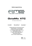
User's Guide OctaMic / OctaMic D Portable Professional Mic Preamp 8-channel Microphone / Line Preamp with Line Outputs Universal Power Supply Input Optional 8-Channel 192 kHz 24 Bit ADC AES-3 24 Bit Interface Contents 1 2 3 4 Introduction............................................................ 3 Package Contents .................................................. 3 Brief Description and Characteristics................... 3 Technical Specifications ....................................... 3 4.1 Analog................................................................... 3 4.2 ADC Modul............................................................ 4 5 Power Supply ......................................................... 4 6 Operation and Usage 6.1 Controls................................................................. 5 6.2 Mic/Line Inputs ...................................................... 6 6.3 Line Outputs.......................................................... 6 7 The ADC Module 7.1 DIP Switches ......................................................... 7 7.2 External Synchronization....................................... 8 8 Digital Outputs 8.1 AES – Sub-D......................................................... 9 8.2 ADAT Optical .......................................................10 9 Word Clock 9.1 Operation and Technical Background ...................11 9.2 Cabling and Termination ......................................12 10 Technical Background 10.1 DS - Double Speed.............................................13 10.2 QS – Quad Speed ..............................................13 10.3 AES/EBU – SPDIF .............................................14 11 Accessories ...........................................................15 12 Warranty ................................................................15 13 Appendix ...............................................................15 14 Block Diagram OctaMic ........................................16 15 CE / FCC Compliance............................................17 User's Guide OctaMic © RME 2 1. Introduction Thank you for choosing the OctaMic. This unique Mic Preamp allows to connect any kind of microphone to any line level inputs. Thanks to the option of battery-powered operation and removable rack ears, the OctaMic makes an ideal companion to the Hammerfall DSP System in mobile recording situations. But excellent signal/noise ratio, sophisticated discrete Class-A technology, and lots of professional features make the OctaMic your first choice also in studio use! 2. Package Contents Please check that your OctaMic's package contains each of the following: • OctaMic • User's guide • Power supply 12 V / 1.25 A and power cord 3. Brief Description and Characteristics • • • • • • • • • • 8 separate microphone inputs with discrete Class-A frontend Phantom power 48V, low cut and phase switchable per channel 48V, Clip and Level LED per channel Gain +10 dB up to +60 dB adjustable per channel Reference level switchable Hi Gain / +4 dBu / -10 dBV Fully compatible to RME's ADI-8 series and HDSP series Servo balanced inputs and outputs Wide frequency response with special RF input filters Wide operating voltage range 100% hum-free via internal switching regulators 4. Technical Specifications • • • • Current drawn at 12 Volt operating voltage: 850 mA (10 Watts) Accepted power supply voltage DC 8 V – 28 V, AC 8 V – 20 V. Dimensions: 483 x 44 x 205 mm Weight: 2 kg 4.1 Analog • • • • • • • • • • Inputs: XLR or 1/4" TRS (stereo) jack, servo balanced Impedance: 2 kOhm Signal to Noise ratio (SNR): 129 dB EIN @150 Ohm THD: 0.006% @ 30 dB Gain Crosstalk: > 110 dB Frequency response –0.5 dB: 5 Hz - 200 kHz Line Out: 1/4" TRS (stereo) jack, servo balanced Maximum output level: +21 dBu Output impedance: 47 Ohm Output level switchable Hi Gain / +4 dBu / -10 dBV • SNR ADC Module: > 110 dBA • Sample rate range ADC Module: 28 kHz – 200 kHz • THD ADC Module: < 0.00032 %, < -110 dB User's Guide OctaMic © RME 3 4.2 ADC Modul AES Input • • • • • 1 x XLR via 25 pin D-sub, transformer balanced, ground-free, according to AES3-1992 High-sensitivity input stage (< 0.3 Vss) SPDIF compatible (IEC 60958) Lock range: 27 kHz – 200 kHz Jitter when synced to input signal: < 2 ns Wordclock Input • • • • • • • • BNC, not terminated (10 kOhm), switch for internal termination 75 Ohm Automatic Double/Quad Speed detection and internal conversion AC-coupling, not effected by DC-offsets within the network Signal Adaptation Circuit: signal refresh through auto-center and hysteresis Overvoltage protection Level range: 1.0 Vss – 5.6 Vss Lock range: 27 kHz – 200 kHz Jitter when synced to input signal: < 2 ns AES/EBU Outputs • • • • • 4 x via 25 pin D-Sub, transformer balanced, ground-free, according to AES3-1992 Output voltage Professional 4.5 Vss, Consumer 2.1 Vss Format Professional according to AES3-1992 Amendment 4 Format Consumer (SPDIF) according to IEC 60958 Single Wire: 4 x 2 channels 24 bit, up to 96 kHz ADAT Optical • 2 x TOSLINK • Standard: 8 channels 24 bit, up to 48 kHz • Sample Split (S/MUX): 2 x 8 channels 24 bit / 48 kHz, equalling 8 channels 24 bit 96 kHz 5. Power Supply In order to make operating the OctaMic as flexible as possible, the unit contains a switching regulator of the latest technology, which not only has a high efficiency (> 90%), but also prevents internal hum noise by operating at 150 kHz. Another advantage: the OctaMic accepts any power supply with voltages between 8 and 28 V DC, no matter which polarity, and even between 8 and 20 V AC. Given the power supply can deliver the current needed. The supplied high-quality switching power supply, 12 V / 1.25 A, not only accepts any mains voltage between 100 V and 240 V (usable world-wide), but is also fully regulated against voltage fluctuations. Additionally it only weighs 150 g in spite of its high power of 15 Watts. The large voltage range of the OctaMic also allows for the use of a rechargeable lead-battery instead of a power supply, for completely independent mobile operation. A matching connection cable (power jack to terminals 6.3 mm) is available from RME. A Panasonic LCR122R2PG battery, 12 V 2.2 Ah, can operate the OctaMic for 2 hours. User's Guide OctaMic © RME 4 6. Operation and Usage 6.1 Controls The front of the OctaMic has the gain knobs, switches for low cut, phantom power and phase, Clip Hold, Reference Level and several status LEDs: +48V (LED) lights up when phantom power is active. Phantom power should only be activated when using condensor microphones which require such a power supply. The CLIP LED has been designed to act like the OVR LEDs of the ADI-8 series. It lights up 2 dB before the chosen reference level plus a headroom of 9 dB. At Hi Gain the LED lights up at +17 dBu output level, selecting +4 dBu it lights up at +11 dBu. SIG (Signal) indicates the presence of an input signal. The LED has a detection range of more than 50 dB using multiple brightness states. With this, SIG acts as useful level control, helping to set GAIN correctly. GAIN allows for a stepless and very precise adjustment of the amplification between +10 dB and +60 dB. +48V (switch) activates phantom power. Phantom power should only be activated when using condensor microphones which require such a power supply, and only on the specific channel. LO CUT activates a hi-pass at 80 Hz, 18 dB per octave. This filter can remove rumble and other low frequency noise. PHASE changes the polarity. Phase cancellations and sound changes can be caused by using multiple microphones at different places, or wrongly soldered cables. In such cases PHASE can eliminate the error by adding an additional phase inversion. Clip Hold is activated by pressing the key for two seconds. As soon as an overload is detected, the corresponding Clip LED begins to flash once per second. With this, a momentary overload stays visible for a longer time. Pressing the key once resets the Clip display. Pressing the key again for two seconds deactivates the Clip Hold mode. Hi Gain / +4 dBu / -10 dBV: Defines the reference level of the Line Level Outputs. See chapter 6.3, Line Outputs. The back of the OctaMic has the 8 analog inputs and outputs, the power supply connector AUX, the analog D-sub output, or the optional ADC module (see chapter 7) with all the digital inputs and outputs. MICROPHONE / LINE INPUTS: 8 Neutrik XLR / TRS combo jacks. Thanks to the servo balanced designs and a high maximum input level (+10 dBu), the inputs can be used balanced or unbalanced, with XLR or TRS jack, with microphone or line levels – nearly everything is possible. LINE LEVEL OUTPUTS: 8 TRS (stereo) jacks. The electronic output stage is built in a servo balanced design, handling monaural (unbalanced) and stereo jacks (balanced) correctly. AUX: Connect power supply, lead-battery or battery. See chapter 5, Power Supply. User's Guide OctaMic © RME 5 6.2 Mic/Line Inputs The OctaMic offers 8 balanced Mic and Line inputs via 1/4" TRS (stereo) and XLR combo jacks. The electronic input stage is built in a servo balanced design which handles monaural and stereo jacks correctly. When used unbalanced it automatically corrects the gain by 6 dB. When using unbalanced cables with stereo TRS jacks, the 'ring' contact of the cable's jack should be connected to pin 1 (ground). Otherwise noise may occur, caused by the unconnected negative input of the balanced input. The pinout follows international standards. XLR pin 2 + or hot, pin 3 – or cold, pin 1 ground. TRS tip + or hot, ring – or cold. 6.3 Line Outputs The 8 short circuit protected, low impedance and servo balanced line outputs are available as (stereo) 1/4" TRS jacks. The electronic output stage is built in a servo balanced design which handles monaural and stereo jacks correctly. When used unbalanced it automatically corrects the gain by 6 dB. The pinout follows international standards. TRS tip + or hot, ring – or cold. To maintain an optimum level for devices connected to the analog outputs, the OctaMic includes a switch which allows to change the reference level of all 8 outputs simultaneously. The OctaMic can generate a maximum level of +21 dBu without distortion. However, the CLIP LED has been designed to act like the OVR LEDs of the ADI-8 series. It lights up 2 dB before the reference level selected on the back of the unit, plus a headroom of 9 dB, is reached. At Hi Gain the LED lights up at +17 dBu output level, selecting +4 dBu it lights up at +11 dBu, selecting –10 dBV it lights up at 0 dBV. Setting Hi Gain +4 dBu -10 dBV Reference +19 dBu +13 dBu +2 dBV Clip LED +17 dBu +11 dBu 0 dBV True Clip +21 dBu +15 dBu +4 dBV ADC Level -2 dBFS -2 dBFS -2 dBFS This also means that the CLIP LED lights up 4 dB before the OctaMic actually reaches the maximum level. Such an additional headroom is considered to be useful in real world operation. The chosen reference level has no meaning for the ADC module. The ADC modul is designed for a level of –2 dBFS as soon as the Clip LED lights up. Selecting +4 dBu the output signal is attenuated by 6 dB, so for the same output level the amplification has to be increased via GAIN. With this trick the OctaMic reaches the maximum signal to noise ratio on +4 dBu based inputs (like our ADI-8 series), because microphone preamps have better EIN values at higher amplification. In case of an extreme recording situation, where the gain of the OctaMic is no longer sufficient, selecting Hi Gain will again provide the highest amplification possible. The same is true and even more efficient at –10 dBV. In this case the output level is reduced by around 14 dB – the same happens to the basic noise of the unit! User's Guide OctaMic © RME 6 7. The ADC Module The ADC Module replaces the analog D-sub output by a high quality digital converter card. The card includes clock generation, clock recovery (SteadyClock) and AD-conversion. 7.1 DIP Switches The DIP switches are used to configure the ADC Module. The following diagram, also printed on the back of the unit, shows the function controlled by each switch. DIP Switch 1 2 3 4 5 6 Function External synchronization source AES (D-sub) or word clock (BNC) Clock internal (Master) or external (Slave) Internal Clock 44.1 kHz or 48 kHz Activates Double Speed Mode* Activates Quad Speed Mode* AES output signal Professional or Consumer *Note on DIP switch 4/5: At internal clock, the switches DS and QS multiply the value set with switch 3 by a factor of 2 or 4. So if switch 3 is set to 48 kHz, switch 4 will turn it into 96 kHz, switch 5 turns it into 192 kHz. At external clock switch 3 is of no meaning, because the unit is synchronized to the incoming clock. However, switch 4 and 5 define the frequency range between Single Speed, Double Speed and Quad Speed. For example if the OctaMic shall operate at 176.4 or 192 kHz, switch 5 has to be set to the lower position. The OctaMic will now generate an output signal in the Quad speed range (176.4 or 192 kHz), even with a word clock input signal of only 44.1 kHz, or an AES input signal signal of 96 kHz. User's Guide OctaMic © RME 7 7.2 External Synchronization The inputs of the ADC Module are used for external synchronization only. In case the clock shall not be generated internally (operation mode Master), an external synchronization (operation mode Slave) is available via word clock or AES (SPDIF). SteadyClock, integrated into the ADC Module, guarantess exceptional performance in all clock modes. Thanks to a highly efficient jitter suppression, the AD-conversion always operates on highest sonic level, being completely independent from the quality of the incoming clock signal. And even in an error state SteadyClock will help: when the current word clock source fails, the last valid sample rate will be held automatically. Wordclock - BNC The transformer balanced, ground-free word clock input is activated by DIP switches 1 and 2. Both switches must be set to their lower position. The word clock input is shipped as high impedance type (not terminated). A push switch allows to activate internal termination (75 Ohms). The switch is found beside the BNC socket. Use a small pencil or similar and carefully push the blue switch so that it snaps into its lock position. Another push will release it again and de-activate the termination. Thanks to RME's Signal Adaptation Circuit, the word clock input still works correctly even with heavily mis-shaped, dc-prone, too small or overshoot-prone signals. Thanks to automatic signal centering, 300 mV (0.3V) input level are sufficient in principle. An additional hysteresis reduces sensitivity to 1.0 V, so that over- and undershoots and high frequency disturbances don't cause a wrong trigger. Due to the ADC Module's outstanding clock control a synchronization of the output signal to the input signal is not only possible at identical sample rates, but also at half, quarter, double and quad sample rates! Example 1: DIP switch 3/4/5 in upper position results in a sample rate of 44.1 kHz. The external synchronization source (word clock or AES) can now be 44.1 kHz, 88.2 kHz or 176.4 kHz. Example 2: DIP switch 3/5 in lower position results in a sample rate of 192 kHz. The external synchronization (word clock or AES) source can now be 48 kHz, 96 kHz or 192 kHz. AES – D-sub Using the D-sub connector, an AES, AES/EBU or SPDIF signal can be used for synchronization. For this to work, DIP switch 1 has to be set to the upper position, DIP switch 2 to lower position. The D-sub connector uses the widely known and often found pinout of the Tascam recorders (TEAC). Therefore multicores D-sub to XLR can be ordered easily. These cable have 4 XLR outputs male and 4 XLR inputs female. The ADC Module's synchronization input uses AES 1 (see chapter 8.1, AES D-sub). The input is transformer balanced and ground-free. Thanks to a highly sensitive input stage, also SPDIF signals can be processed by using a simple cable adapter (RCA/XLR). User's Guide OctaMic © RME 8 To achieve this, pins 2 and 3 of an XLR plug are being connected to the two contacts of a Phono/RCA plug. The ground shield of the cable is only connected to pin 1 of the XLR plug. Using the AES input, a synchronization is again possible at half, quarter, double and quad sample rates, see above. 8. Digital Outputs 8.1 AES – D-sub The ADC Module provides the four AES/EBU outputs via a 25 pin D-sub connector. The D-sub connector uses the widely known and often found pinout of the Tascam recorders (TEAC). Therefore multicores D-sub to XLR can be ordered easily. These cable have 4 XLR outputs male and 4 XLR inputs female. The inputs 2 to 4 are not used by the ADC Module. Every output is transformer-balanced and compatible to all devices with AES/EBU port. The format is set by DIP switch 6 to Professional or Consumer. If AES PRO is chosen, the output level is almost 5V. If CON (Consumer) is chosen, the output signal will have a channel status compatible to SPDIF, and the output level will be reduced to 2V. Connecting devices with coaxial SPDIF ports to the ADC Module's outputs (the XLR Multicore) is accomplished by simple cable adapters (XLR/RCA). To achieve this, pins 2 and 3 of an XLR plug are being connected to the two contacts of a Phono/RCA plug. The ground shield of the cable is only connected to pin 1 of the XLR plug. The Channel Status of the ADC Module has been implemented according to AES3-1992 Amendment 4. • • • • • • • • 32* / 44.1 / 48 / 64* / 88.2 / 96 / 176.4 / 192 kHz according to sample rate Audio use No Copyright, Copy permitted Format Consumer oder Professional Category General, Generation not indicated 2-Channel, No Emphasis Aux bits Audio use, 24 Bit Origin: 8MIC * This value is set automatically in external synchronization mode as soon as the sample rate is recognized. Note that most consumer-orientated equipment (with optical or phono SPDIF inputs) will only accept signals in ‘Consumer’ format! The status 'Professional' should always be active when sending data to a device with AES/EBU input (when XLR connectors are used). User's Guide OctaMic © RME 9 Pinout D-sub Signal D-sub Signal D-sub In 1/2+ 24 In 1/212 In 3/4+ 10 In 3/423 In 5/6+ 21 In 5/69 In 7/8+ 7 In 7/820 Out 1/2+ 18 Out 1/26 Out 3/4+ 4 Out 3/417 Out 5/6+ 15 Out 5/63 Out 7/8+ 1 Out 7/814 GND is connected to pins 2, 5, 8, 11, 16, 19, 22, 25. Pin 13 is not connected. 8.2 ADAT Optical The ADC Module provides two digital outputs in ADAT optical format. As the ADAT optical signal is physically specified up to 48 kHz only, the ADC Module automatically activates Sample Split mode (S/MUX) at 88.2 and 96 kHz, distributing the data of one input to two output channels. The internal frequency stays at 44.1/48 kHz. Therefore the sample clock at the ADAT outputs is only half the frequency of the AES outputs. As interesting as this is – you don't need to think about it. 96 kHz capable ADAT hardware, like all current RME digital interfaces, re-combine the data automatically. The user (and the DAW software) does not see any split data, but just single channels at the expected double sample rate. At frequencies not higher than 48 kHz (Single Speed), the outputs MAIN and AUX operate simultaneously and carry the same audio data. With this it is possible to distribute the output signal to two devices (2 x ADAT splitter). Up to 96 kHz (Double Speed), the ADAT outputs can be used in parallel to the AES outputs. In Quad Speed mode (128 kHz up to 192 kHz), the ADAT outputs are operated synchronously at Single Speed sample clock, but do not provide any audio data. The ADAT optical outputs of the ADC Module are fully compatible to all ADAT optical inputs. A usual TOSLINK cable is sufficient for connection. ADAT Main Interface for the first or only device receiving an ADAT signal from the OctaMic. Carries the channels 1 to 8. When sending a Double Speed signal, this port carries the channels 1 to 4. In Quad Speed mode ADAT MAIN carries an empty but synchronous ADAT signal. ADAT AUX Copy of the data at the MAIN output. When sending a Double Speed signal, this port carries the channels 5 to 8. In Quad Speed mode ADAT AUX carries an empty but synchronous ADAT signal. User's Guide OctaMic © RME 10 9. Word Clock 9.1 Operation and Technical Background Correct interpretation of digital audio data is dependent upon a definite sample frequency. Digital signals can only be processed or transferred between devices if these share the same clock. Otherwise the signals are misinterpreted, causing distortion, clicks/crackle or dropouts. AES/EBU, SPDIF and ADAT are self-clocking, so an additional line for word clock could be considered redundant. In practice however, using several devices at the same time can cause problems. For example, if devices are connected in a loop without there being a defined ‘master’ device, self-clocking may break down. Besides, the clocks of all devices must be synchronized from a single source. Devices without SPDIF inputs (typically playback devices such as CD players) cannot be synchronized via self-clocking. In digital studios, synchronization requirements can be met by connecting all devices to a central sync source. For instance, the master device could be a mixing desk, sending a reference signal - word clock - to all other devices. However, this will only work if all the other devices have word clock inputs (e.g. some professional CD players) allowing them to run as slaves. This being the case, all devices will receive the same clock signal, so there is no fundamental reason for sync problems when they are connected together. But word clock also has some disadvantages. The word clock is based on a fraction of the actually needed clock. For example SPDIF: 44.1 kHz word clock (a simple square wave signal) has to be multiplied by 256 inside the device using a special PLL (to about 11.2 MHz). This signal then replaces the one from the quartz crystal. Big disadvantage: because of the high multiplication factor the reconstructed clock will have great deviations called jitter. The jitter of a word clock is typically 15 times higher as when using a quartz based clock. The end of these problems should have been the so called Superclock, which uses 256 times the word clock frequency. This equals the internal quartz frequency, so no PLL for multiplying is needed and the clock can be used directly. But reality was different, the Superclock proved to be much more critical than word clock. A square wave signal of 11 MHz distributed to several devices - this simply means to fight with high frequency technology. Reflections, cable quality, capacitive loads - at 44.1 kHz these factors may be ignored, at 11 MHz they are the end of the clock network. Additionally it was found that a PLL not only generates jitter, but also also rejects disturbances. The slow PLL works like a filter for induced and modulated frequencies above several kHz. As the Superclock is used without any filtering such a kind of jitter and noise suppression is missing. No wonder Superclock did not become a commonly accepted standard. The actual end of these problems is offered by RME's SteadyClock technology. Combining the advantages of modern and fastest digital technology with analog filter techniques, re-gaining a low jitter clock signal of 11 MHz from a slow word clock of 44.1 kHz is no problem anymore. Additionally, jitter on the input signal is highly rejected, so that even in real world usage the regained clock signal is of highest quality. User's Guide OctaMic © RME 11 9.2 Cabling and Termination Word clock signals are usually distributed in the form of a network, split with BNC T-adapters and terminated with resistors. We recommend using off-the-shelf BNC cables to connect all devices, as this type of cable is used for most computer networks. You will find all the necessary components (T-adapters, terminators, cables) in most electronics and/or computer stores. Ideally, the word clock signal is a 5 Volt square wave with the frequency of the sample rate, of which the harmonics go up to far above 500 kHz. To avoid voltage loss and reflections, both the cable itself and the terminating resistor at the end of the chain should have an impedance of 75 Ohm. If the voltage is too low, synchronization will fail. High frequency reflection effects can cause both jitter and sync failure. Unfortunately there are still many devices on the market, even newer digital mixing consoles, which are supplied with a word clock output that can only be called unsatisfactory. If the output breaks down to 3 Volts when terminating with 75 Ohms, you have to take into account that a device, of which the input only works from 2.8 Volts and above, does not function correctly already after 3 meter cable length. So it is not astonishing that because of the higher voltage, word clock networks are in some cases more stable and reliable if cables are not terminated at all. Ideally all outputs of word clock delivering devices are designed with very low impedance, but all word clock inputs with high impedance, in order to not weaken the signal on the chain. But there are also negative examples, when the 75 Ohms are built into the device and cannot be switched off. In this case the network load is often 2 x 75 Ohms, and the user is forced to buy a special word clock distributor. Note that such a device is generally recommended for larger studios. Also, 75 Ohm cable is almost impossible to find these days. 50 Ohm cable is standard - this will also work as long as the termination resistors are 75 Ohm. The ADC-Module's word clock input can be high-impedance or terminated internally, ensuring maximum flexibility. If termination is necessary (e.g. because the OctaMic is the last device in the chain), push the switch at the back beside the BNC socket. In case the OctaMic resides within a chain of devices receiving word clock, plug a T-adapter into its BNC input jack, and the cable supplying the word clock signal to one end of the adapter. Connect the free end to the next device in the chain via a further BNC cable. The last device in the chain should be terminated using another T-adapter and a 75 Ohm resistor (available as short BNC plug). Of course devices with internal termination do not need T-adaptor and terminator plug. User's Guide OctaMic © RME 12 10. Technical Background 10.1 DS - Double Speed When activating the Double Speed mode the ADC Module operates at double sample rate. The internal clock 44.1 kHz turns to 88.2 kHz, 48 kHz to 96 kHz. The internal resolution is still 24 bit. Sample rates above 48 kHz were not always taken for granted, and are still not widely used because of the CD format (44.1 kHz) dominating everything. Before 1998 there were no receiver/transmitter circuits available that could receive or transmit more than 48 kHz. Therefore a work-around was used: instead of two channels, one AES line only carries one channel, of which the odd and even samples are being distributed to the former left and right channels. By this, you get the double amount of data, i. e. also double sample rate. Of course in order to transmit a stereo signal two AES/EBU ports are necessary then. This transmission mode is being called Double Wire in the professional studio world, and is also known as S/MUX in connection with the ADAT format. The DTRS recorder DA-98HR by Tascam also uses this technique, which is called Dual Line here. Not before February 1998, Crystal shipped the first 'single wire' receiver/transmitters that could also work with double sample rate. It was then possible to transmit two channels of 96 kHz data via one AES/EBU port. But Double Wire is still far from being dead. On one hand, there are still many devices which can't handle more than 48 kHz, e. g. digital tape recorders. But also other common interfaces like ADAT or TDIF are still using this technique. Because the ADAT interface does not allow for sampling frequencies above 48 kHz (a limitation of the interface hardware), the ADI-8 DD automatically uses the described Sample Split method in DS mode. One channel's data is distributed to two channels according to the following table: Analog In DS Signal Port 1 1/2 MAIN 2 3/4 MAIN 3 5/6 MAIN 4 7/8 MAIN 5 1/2 AUX 6 3/4 AUX 7 5/6 AUX 8 7/8 AUX As the transmission of double rate signals is done at standard sample rate (Single Speed), the ADAT outputs still deliver 44.1 kHz or 48 kHz. 10.2 QS – Quad Speed Due to the seldomly found devices using sample rates up to 192 kHz, but even more due to a missing real world application (CD...), Quad Speed has had no broad success so far. An implementation of the ADAT format as double S/MUX would result in two channels per optical output. Devices using this method are not known to us, so we decided to do without this format. The AES outputs provide 192 kHz as Single Wire only. This is forced by the space not available for further D-sub connectors, necessary for Double Wire (Quad Wire...) implementation. User's Guide OctaMic © RME 13 10.2 AES/EBU - SPDIF The most important electrical properties of 'AES' and 'SPDIF' can be seen in the below table. AES/EBU is the professional balanced connection using XLR plugs. The standard is being set by the Audio Engineering Society based on the AES3-1992. For the 'home user', SONY and Philips have omitted the balanced connection and use either Phono plugs or optical cables (TOSLINK). The format called S/P-DIF (SONY/Philips Digital Interface) is described by IEC 60958. Type Connection Mode Impedance Level Clock accuracy AES3-1992 XLR Balanced 110 Ohm 0.2 V up to 5 Vss not specified Jitter < 0.025 UI (4.4 ns @ 44.1 kHz) IEC 60958 RCA / Optical Un-balanced 75 Ohm 0.2 V up to 0.5 Vss I: ± 50ppm II: 0,1% III: Variable Pitch not specified Besides the electrical differences, both formats also have a slightly different setup. The two formats are principally compatible, because the audio information is stored in the same place in the data stream. However, there are blocks of additional information, which are different for both standards. In the table, the meaning of the first byte (#0) is shown for both formats. Already in the first bit there is the decision, whether the following bits should be read as Professional or Consumer information. Byte 0 0 Mode Pro Con Bit 0 P/C P/C 1 Audio? Audio? 2 3 4 5 Emphasis Locked Copy Emphasis 6 7 Sample Freq. Mode As can be seen, the meaning of the following bits differs quite substantially in both formats. If a device like a common DAT recorder only has an SPDIF input, it usually understands only this format. In most cases, it will switch off when being fed Professional-coded data. The table shows that a Professional-coded signal would lead to malfunctions for copy prohibition and emphasis, if being read as Consumer-coded data. This actually happened in former times, but if found today then it was implemented to force the costumer to buy a more expensive device. Nowadays many devices with SPDIF input can handle Professional subcode. Devices with AES3 input almost always accept Consumer SPDIF (passive cable adapter necessary). User's Guide OctaMic © RME 14 11. Accessories Part number Description 37011 Power supply for HDSP CardBus card Robust and light weigth switching power supply, 100V-240V AC, 12V 1.25 A DC. 12. Warranty Each individual OctaMic undergoes comprehensive quality control and a complete test at RME before shipping. The usage of high grade components allow us to offer a full two year warranty. We accept a copy of the sales receipt as valid warranty legitimation. If you suspect that your product is faulty, please contact your local retailer. The warranty does not cover damage caused by improper installation or maltreatment - replacement or repair in such cases can only be carried out at the owner’s expense. RME does not accept claims for damages of any kind, especially consequential damage. Liability is limited to the value of the OctaMic. The general terms of business drawn up by Synthax Audio AG apply at all times. 13. Appendix RME news, driver updates and further product information are available on our website: http://www.rme-audio.com Trademarks All trademarks, registered or otherwise, are the property of their respective owners. RME is a registered trademark of RME Intelligent Audio Solutions. OctaMic is a trademark of RME Intelligent Audio Solutions. Copyright Matthias Carstens, 3/2004. Version 1.0 Although the contents of this User’s Guide have been thoroughly checked for errors, RME can not guarantee that it is correct throughout. RME does not accept responsibility for any misleading or incorrect information within this guide. Lending or copying any part of the guide or the RME Driver CD, or any commercial exploitation of these media without express written permission from RME Intelligent Audio Solutions is prohibited. RME reserves the right to change specifications at any time without notice. User's Guide OctaMic © RME 15 14. Block Diagram OctaMic User's Guide OctaMic © RME 16 15. CE / FCC Compliance Statements CE This device has been tested and found to comply with the EN55022 class B and EN50082-1 norms for digital devices, according to the European Council directive on counterpart laws in the member states relating to electromagnetic compatibility (EMVG). FCC This device has been tested and found to comply with the requirements listed in FCC Regulations, part 15 for Class ‘B’ digital devices. Compliance with these requirements provides a reasonable level of assurance that your use of this product in a residential environment will not result in harmful interference with other electronic devices. This equipment generates radio frequencies and, if not installed and used according to the instructions in the User’s Guide may cause interference harmful to the operation of other electronic devices. Compliance with FCC regulations does not guarantee that interference will not occur in all installations. If this product is found to be the source of interference, which can be determined by turning the unit off and on again, please try to eliminate the problem by using one of the following measures: • Relocate either this product or the device that is being affected by the interference • Use power outlets on different branch circuits, or install AC line filters • Contact your local retailer or any qualified radio and television engineer FCC compliance statement: Tested to comply with FCC standards for home or office use. User's Guide OctaMic © RME 17