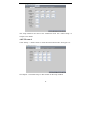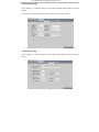
1
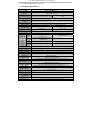
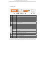
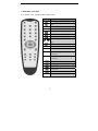
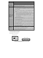
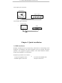
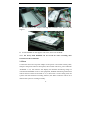
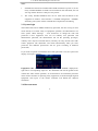
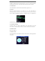
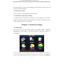
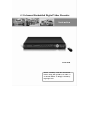
4 / 8-channel Embedded Digital Video Recorder Instruction H.246 DVR Please carefully read the instruction before using this product, in order to avoid the failure or danger caused by improper uses. Notes ..............................................................................................................3 Chapter 1 Overview ...............................................................................................3 1.1 Introduction..............................................................................................3 1.2 Packaging and accessories .......................................................................4 1.3 Main features ...........................................................................................4 1.4 Technical parameters................................................................................5 1.5 Product appearance and interface definition ............................................6 1.5.1 Front panel ....................................................................................6 1.5.2 Back panel.....................................................................................7 1.6 Remote controller.....................................................................................8 1.7 Mouse.......................................................................................................9 1.8 Alarm input and output ..........................................................................10 Chapter 2 Quick installation ................................................................................ 11 2.1 HDD Installation .................................................................................... 11 2.2 Boot........................................................................................................12 2.3 System login...........................................................................................13 2.4 Shortcut menu ........................................................................................13 2.4.1 Main menu ..................................................................................14 2.4.2 Lock ............................................................................................14 2.4.3 Channel switching.......................................................................14 2.4.4 Video search ................................................................................14 2.4.5 PTZ Control ................................................................................14 2.4.6 Mute/open volume ......................................................................15 2.4.7 Manual recording/stop recording ................................................15 Chapter 3 Advanced settings................................................................................15 3.1 Main menu .............................................................................................15 3.2 Recording mode .....................................................................................16 3.3 Video search...........................................................................................17 3.3.1 Video search ................................................................................17 3.3.2 Log search ...................................................................................20 3.4 Backup ...................................................................................................20 3.5 Harddisk management............................................................................21 3.6 Basic setup .............................................................................................23 3.6.1 System language .........................................................................23 3.6.2 Time setup ...................................................................................24 3.6.3 User password .............................................................................24 3.6.4 Display setup...............................................................................25 3.6.5 Video/Audio setup.......................................................................26 3.7 Advanced functions................................................................................27 3.7.1 Alarm setup .................................................................................28 3.7.2 System info .................................................................................30 3.7.3 Motion detection .........................................................................30 3.7.4 Mobile phone monitoring............................................................32 3.7.5 System maintenance....................................................................39 3.7.6 PTZ setup ....................................................................................40 3.7.7 Network setup .............................................................................41 3.8 Domain name application ......................................................................43 3.9 Port mapping..........................................................................................47 Chapter 4 DVR network ......................................................................................49 4.1 Functional characteristics.......................................................................49 4.2 Installation and download of controls ....................................................49 4.3 IE log-in .................................................................................................50 4.4 Real-time preview ..................................................................................51 4.5 Record playback.....................................................................................52 4.6 Recording mode .....................................................................................53 4.7 Alarm setup ............................................................................................53 4.8 PTZ control ............................................................................................54 4.9 Network setup ........................................................................................55 4.10 System setup ........................................................................................55 4.11 Host info...............................................................................................56 Appendix 1. Q&A ........................................................................................57 Appendix 2 harddisk space occupation calculation .....................................60 Appendix 3 Player........................................................................................60 Appendix 4 System connection diagram......................................................62 2 4 / 8-channel Embedded Digital Video Recorder Notes The power supply of this DVR is provided through DC19V adapter, please check the power outlet before installation and ensure it can meet the requirements of adaptor; Do not place the DVR at a place subject to rain or moisture; Do not install the DVR at a place subject to violent vibration; Do not install the DVR at a place subject to direct sunlight, and be far away from heat and high temperature environment; The DVR’s back panel shall be 15cm or more away from other objects or wall, to facilitate fan cooling; The DVR shall work under temperature, humidity and voltage according to its technical specifications; The space where DVR installed shall not be stored with corrosive chemicals that may produce volatile gases, to avoid to affect the DVR’s life; The DVR shall be installed in a space without much dust, and the environment should be kept clean and tidy; Proper grounding shall be installed during operation; DVR should be installed to ensure the proper connectivity with other devices. Please buy harddisk from official channel to meet DVR’s long time and much data reading and writing requirements. Chapter 1 Overview 1.1 Introduction This product is a consumer-oriented 4/8-channel CIF real-time network DVR, and the industry's most advanced SOC technology and standard H.264 encoding method is adopted, so that the image quality is higher, network transmission effect is better and system is more stable; the body is made under stylish appearance design and sophisticated manufacturing process, the 1U standard 3 chassis is suitable for small-scale monitoring places such as shop, supermarket, residential, school, hotel, Internet cafe, family and other civilian sites where require more on video quality, network transmission and real-time playback. 1.2 Packaging and accessories Following parts are included in the package: ◎ One IR remote controller ◎ A pair of remote controller batteries ◎ One piece of product certificate ◎ One piece of product warranty card ◎ One piece of product instruction ◎ Several SATA harddisk data cables ◎ One DC19V2.1A power adapter ◎ HDD support (already installed) and a set of mounting screws. ◎ One piece of CD. 1.3 Main features ◎ Standard H.264 video compression format ◎ 16-bit true-color semi-transparent graphical menu interface, menu options tip ◎ A variety of recording modes: manual, timing, movement and alarm recording ◎ Optimized four-channel simultaneous playback (single playback for eight-channel ones) ◎ A variety of backup (U disk, mobile harddisk, network) ◎ One USB2.0 for data backup, one USB1.1 for the mouse operation ◎ Multi-functional operation, recording, playback, monitor, backup and network transmission can be realized at the same time ◎ Dual stream technology ◎ Support network to implement multi-screen real-time browsing, parameter setting, copy or playback ◎ Support phone monitoring ◎ Support event classification and precise time search and playback ◎ Defaulted parameter value fast recovery 4 4 / 8-channel Embedded Digital Video Recorder ◎ Flexible USB interface for mouse 1.4 Technical parameters Four-channel Video standard Video compression format Eight-channel PAL / NTSC selectable Main profile H.264 BNC 8-channel input/2-channel output support (optional) Video input/output BNC 4-channel input/2-channel output VGA output Audio compression 8kHz × 16bit ADPCM method Audio input/output RCA 1-channel input, 1-channel output. Alarm type Motion detection, sensor trigger, video loss, disk full, disk error. 4-channel alarm input/1-channel 8-channel alarm input /1-channel Alarm input/output alarm output alarm output Display 1/4-channel switchable 1/4/8-channel switchable Display resolution PAL: D1 (704 × 576) NTSC: D1 (720 × 480) Display frame rate Single-channel PAL: 25fps, NTSC: 30fps CIF(352×288) HD1(704×288) PAL CIF(352×288) D1(704×576) Playback CIF(360×240) HD1(720×240) Resolution NTSC CIF(360×240) D1(720×480) PAL 25fps@D1/50fps@HD1/100fps@CIF 200fps@CIF Recording Total frame NTSC 30fps@D1/60fps@HD1/120fps@CIF 240fps@CIF rate Recording mode Start automatic continuous, timing video, motion detection, trigger alarm. Video packing time 15/30/45/60 minutes adjustable Harddisk Network protocol Network functionality USB1.0 interface Support one SATA harddisk drive (maximum capacity is 1T) Support DHCP, UDP, TCP/IP, DNS, DDNS, PPPOE and other protocols. Support IE browsing, real-time network monitor and network DVR parameter setting. USB2.0 interface Support mobile harddisk and USB disk backup and upgrade. Normal playback, fast forward playback, fast backward playback, manual single-frame slow motion. Playback mode Network interface Support mouse operation One RJ45 10M/100M self-adaptive Ethernet port PTZ control Built-in RS-485 interface, support Pelco-D and Pelco-P protocol support USB disk backup, mobile harddisk backup, USB burner backup and Backup function network backup Power adapter DC 19V/2.1A Power consumption 15 ~ 20W (excluding harddisk) Operating 0℃~+50℃ temperature Operating humidity 10%~90% Dimensions (mm) 354 × 230 × 45mm (length × width × height) 5 1.5 Product appearance and interface definition 1.5.1 Front panel ② ③ ④ ① No. 1 2 3 4 5 6 Definition No. Power switch Manual recording 7 Stop recording ⑦ ⑧ ⑨ ⑩ 11 12 13 14 No. Definition MENU: Main menu 9 Confirm PTZ: PTZ control 10 ESC: Exit/Return 11 REC: Video search recording indicator 8 ⑥ Definition Video Mute ⑤ 12 mode indicator Power LED accessed to USB disk for backup or upgrade connection indicator ALARM: Alarm right 12 2.0 USB interface, which can be NET: Network Display Directional keys: up, down, left and 6 13 Remote control infrared receiver 14 USB mouse interface 4 / 8-channel Embedded Digital Video Recorder 1.5.2 Back panel ① No. Physical ② ③④ ⑤ ⑥ ⑦ ⑧ ⑨ ⑩ Interface description interface 1 Video input Connect analog video (camera) signal input, standard BNC connector 2 Video output Two video outputs, connect TV or monitor, standard BNC connector 3 Audio output Connect the audio output 4 Audio input Connect active audio signals, such as pickup 5 6 7 8 Network Connect the Ethernet interface VGA port Connect VGA monitor, such as computer monitor Power interface DC 19V/2.1A RS485+,- Connect the RS485 interfaces in equipments like PTZ ALARM 1,2 Connect alarm switch output DC12V SENSOR 1~8 G 9 Fan 10 Grounding Connect power supply in DC relay, power supply capacity is 1A, not short-circuit Connect alarm switch input, 4-channel equipment 4-alarm inputs, 8-channel equipment 8-alarm inputs Ground Heat emission, please check the fan during routine maintenance, and make a timely replacement To eliminate electrostatic from body Note: The figure above is 8-channel DVR back panel. 4-channel DVR back panel can only allow 4-channel video inputs and 4-channel alarm inputs, and the 7 rest is as same as 8-channel DVR. 1.6 Remote controller For reference only, the real product shall prevail. Key Functional definition Spare keys Mute 0~9 Channel selection; number keys PTZ PTZ Control Single and multi-split screen Quit shortcut menu Shortcut menu Direction buttons: Next, on the left and right OK ESC Exit / Return MENU Enter the main menu STARTREC Start recording (please refer to 2.4.7 for the method) STOPREC Stop recording (please refer to 2.4.7 for the method) Video Search Stop playing Fast backward Fast forward Frame movement F1, F2 Spare key 8 4 / 8-channel Embedded Digital Video Recorder 1.7 Mouse This equipment supports USB1.1 mouse, so the user can operate with mouse (mouse operation is as same as WINDOWS operating setting) to realize menu functions. It is just ok to insert the mouse with USB interface to the mouse interface in this equipment. 9 Mouse action Right button Double mouse left click Click the left mouse button Mouse movement Function Enter system main menu: real-time screen preview, single mouse left click Single left click the functional menu icon, and enter menu setting page The image in a channel can be enlarged by double click real-time monitoring and playback screen, it can be recovered into monitoring and multi-split image after double click again 1. Access to volume adjustment, color adjustment and PTZ control menu. The volume adjustment, color adjustment and PTZ control can set only one channel, please select corresponding screen if multi-screen mode is on prior to setting. 2. If you single click mouse button in volume adjustment and PTZ control: A: PTZ control is available if clicking direction or "+ and -" icon; B: There is a volume bar in volume control interface. Move mouse to a position and click right button, the corresponding volume will be shown in the right side of the volume bar, click "×" to exit; C: The operations like color adjustment can be referred to above volume adjustment. 3. If there are many options in the option box, click the left button and drop-down menu will be shown. 4. Fast forward and fast backward function can be realized by left clicking in video playback interface. 5. Click the left button or right button can activate the soft keyboard in input box, clicking right button can switch English and Chinese input state; the number, symbol and English word capitalization can be realized only by clicking. 6. The Chinese spell is also available via the soft keyboard input when Chinese input, its input method is as same as remote control; left button can be used for turning page. 1. Click left button and move can adjust the parameters in volume adjustment and color adjustment interface, there is corresponding parameter display in right side when movement. 2. Click left button and move the motion box can set the dynamic detection zone in motion detection zone. 1.8 Alarm input and output Alarm input close connection: Infra Infrared alarm 47kΩ + - NC DVR ALARM IN C 10 +12 1 2 3 4 5 6 7 8 GND 4 / 8-channel Embedded Digital Video Recorder Alarm input open connection: Infrared alarm 47kΩ + - NC DVR ALARM IN C 1 2 3 4 5 6 7 8 GND +12 Alarm output open connection: Sound and light l DVR + + Response output - Power Chapter 2 Quick installation 2.1 HDD Installation Harddisk installation must be carried out by technicians to avoid damage to the equipment and harddisk. The DVR mainframe must be powered off before operation. This equipment supports harddisk with SATA harddisk interface. Seagate brand harddisk is recommended. Installation procedures are as follows: A. Open the equipment and a harddisk support can be seen. 11 B. Connect the harddisk data and power cable well C. Put the harddisk into support, and align the harddisk’s screw hole with the support. D. Fix the harddisk on the support with screw, and cover the DVR. Note: the newly fixed harddisk can be served for video recording after formatted on the mainframe. 2.2 Boot Connect the DC19V2.1A power adapter to the power cord socket in back panel, and press the power button in front panel, the recorder will be on, power indicator “POWER” is on, the monitor will display 4/8-channel monitoring image. If non-formatted harddisk exists in the equipment, harddisk formatting information will be shown. If boot-record mode is on, or boot time is in the setting time, the system will start automatic recording function, the “REC” indicator will be on to indicate the system is working normally. 12 4 / 8-channel Embedded Digital Video Recorder Note: 1. If harddisk is failed to be installed when DVR mainframe is power on, or the newly installed harddisk is failed to be formatted on the mainframe, the red “H” logo will be shown in video pre-view picture. 2. The newly installed harddisk must not be used until formatted in the equipment as follows: main interface > harddisk management > harddisk formatting. The system will be restarted after completion of formatting. 2.3 System login The DVR initial code is 000000 without any password, the user can log in main menu directly. For better safety of equipment operation, the administrator can enter system “Basic Settings” – “User Password” to change the code and password of this equipment. You can set ordinary user password and administrator password, the administrator has all the operating privileges, ordinary users only have limited choices, and they can only monitor and video search/ playback. (the mainframe will match automatically when you enter password, and different permissions will be given according to different passwords). If you want to operate in mainframe menu after password is set, the system will display “user login” interface: Equipment code: it is just ok to enter equipment code “000000” displayed on right side in corresponding input box. The defaulted code will be guided to the number box when mouse operation; we recommend to set mainframe password when remote controller is operating many equipments, to divide through targeted equipment code input, or the remote controller will disturb the adjacent mainframe. 2.4 Shortcut menu 13 Click right button in the interface after system startup, quick operations are available to DVR system in the pop-up menu, it can set or control parameters including main menu, lock, video search, PTZ control and video recording. 2.4.1 Main menu Click "Main Menu" to enter the main menu interface, please see 3.1. 2.4.2 Lock When the password function is on (please see 2.3), click right button in monitoring interface, and select "Lock" in the pop-up menu, the system interface can be locked immediately, password is required to log in if operation to mainframe menu is needed. 2.4.3 Channel switching 8-channel DVR can choose eight-channel, front four-channel and back four-channel. 4-channel DVR can choose to switch 4-channel and one-channel. 2.4.4 Video search Please see Chapter 3. 2.4.5 PTZ Control Click right button in main interface and select “PTZ control”, following interface will pop-up: 14 4 / 8-channel Embedded Digital Video Recorder PTZ speed (fast or slow) can be controlled in this interface, zoom, focus and aperture is also controllable. 2.4.6 Mute/open volume Close or open the sound output in the preview mode. 2.4.7 Manual recording/stop recording If “timing record” is on (please see Chapter 3), and recording it not set in this period, "manual recording" and "timing record" is effective. When boot-record mode is on, this function is not available. Chapter 3 Advanced settings 3.1 Main menu The main menu has the “Video Search”, “Recording Mode”, “Harddisk Management”, “Basic Setup”, “Advanced Functions” and “Exit” options, as shown below: Note: The setup of all the submenus below will not be effective until “Enter” is pressed. The setup of this menu will be invalid if you exit directly. A significant 15 characteristic of this product is when you move the cursor to any option, the prompting message of this option will be displayed automatically in the lower part of the screen. 3.2 Recording mode Enter the Recording Mode screen from “Main Menu”—“Recording Mode”, as shown below: Channel: used to select if the video recording function is enabled for the corresponding recording channel. Resolution: available in the 3 levels of highest, high and normal, in which the recording resolution is the highest at the highest level; the 3 levels correspond to the 3 standard resolutions of D1, HD1 and CIF respectively. (Note: This option is available for 4-channel DVRs only, and the resolution of 8-channel DVRs is CIF by default and unchangeable.) Bit rate: available in the 3 levels of highest, high and normal, corresponding to the 3 data stream standards of highest, high and medium bit rates. Audio recording: switching on or off audio recording. Video recording mode: available in the two modes of startup recording and timing recording. Startup recording: starting recording when this unit is energized (It works only if the corresponding channel is enabled in the “Channel” option.) 16 4 / 8-channel Embedded Digital Video Recorder Timing recording: performing recording as scheduled. When “timing recording” is selected, the “Record Time Configuration” button will appear on the right. Move the cursor here and press “Enter” to enter the Record Time Configuration screen, as shown below: Channel: You may choose either “All” or a single channel. Time configuration: First select from the 3 modes of alarm recording, general recording and no recording for your desired recording mode for a certain lattice, and configure specific recording time lattices (each lattice represents 1hr). Each lattice can be configured into different recording modes by marking them into different colors, such as red, green and background color, which represent alarm recording, general recording or no recording within each hour respectively. Packaging time: Left-click or press “Enter” to select the packaging time, with the 4 options of 15min, 30min, 45min and 60min. 3.3 Video search 3.3.1 Video search Enter the Video Search screen from “Main Menu” →“Video Search”, as shown below: This unit supports 3 video search modes: A. Timing playback Time input: First select the corresponding channel and then adjust the date and 17 time to be searched. Left-click or press “Enter” and the direction keys or enter digits directly for year, month, date, hour and minute adjustment, and then click “Playback” to play back the record of this period of time. For 4-channel DVRs, the 4 channels can be played back simultaneously. B. Playback based on record state Enter the year, month and date to be searched in the “Time Input” box and click “Search” to view the record state of this date, as shown below: Month: displaying the record information of every day in the current month. A green block indicates normal recording, a red block indicates alarm recording, and the background color indicates no recording. Click a date on this bar to search the record information of every hour of that day. The search results will be visualized in the “Day” bar below. Date: displaying the recording hours of the current day. Each lattice represents 1hr, and one recording segment is 0.5hr. The presentation of the record state is the same as above. Click a 0.5hr segment of a day directly to enter the record playback of this segment. C. Playback based on file list Enter the year, month and date to be searched in the “Time Input” box and click “Search” to view the record state of this date. Click a certain day on the “Month” bar and then “Detailed File”, and the “Detailed File” screen will pop up, as shown below: Channel selection: There are 5 options: 1, 2, 3, 4 and all (9 options for 8-channel 18 4 / 8-channel Embedded Digital Video Recorder DVRs). After selection and confirmation, which channel file is displayed can be modified in the following list. Record type: There are 3 options: all, normal and alarm. After selection and confirmation, the searched message will be displayed automatically as a list, as shown below: Notes: ① In the “Detailed File” list, by which recording channel is the current record file recorded is displayed at “Channel”, the starting and ending times of record packaging at “Record Time”, the size (unit: MByte) of this record file at “Size”, and the type of this record file at “Type”, with the two options of normal and alarm. The operation of outputting data from the selected record to the USB memory can be performed in the “Backup” check box at the bottom right corner of the screen; ② When you have selected a certain record file from the record list by moving the cursor up and down, press “Enter” to enter the playback screen; ③ If “Record Time Superimposition” has already been enabled in the “Basic Setup” screen, the playback screen will display the clock of recording; if “Record Time Superimposition” is set as “Off” in the “Basic Setup” screen, there will be no clock display on the playback screen; ④ During record playback, press “Slow” for slow play, press “Fast Forward” or “Fast Backward” for fast forward or backward play, or press “Pause/Frame” for pause or frame-by-frame play; press “Exit” to exit from the playback 19 screen and return to the menu of the previous level; ⑤ When the selected record file has been played out, any consecutive record file will be played automatically; if there is no consecutive record file, this unit will return to the detailed file list automatically. 3.3.2 Log search Click the “Log Search” option in the lower part of the Video Search screen to enter the “Log Search” screen: Log type: with the two options of “Alarm” and “Operation” Starting and ending times: setting the time frame of the corresponding log. 3.4 Backup Enter the “Detailed File List” (see 3.3 Video Search) screen for the backup operation. The record file may be backed up by a USB storage device. Before the record file is backed up, the user must insert the peripheral storage device into the USB2.0 20 4 / 8-channel Embedded Digital Video Recorder slot of this unit. This product supports the plug-and-play operation of USB devices. Move the cursor up and down in the Detailed File List screen to select a certain record file. After “Enter” is pressed in the “Backup” check box, a “√” will appear in this box, indicating that this record file has been selected. The move the cursor to the option box on the right and click “Backup”, when the screen will display the backup progress message of the file, as shown below: Notes: 1. When the available space of the backup device is less than the capacity of the record file, the system will prompt the user with “Not Enough Space”; 2. After the record file has been backed up, unplug the backup device directly; 3. See Chapter 4 “DVR Network” for network backup. 3.5 Harddisk management Enter the Harddisk Management screen from “Main Menu” →“Harddisk Management”, as shown below: 21 Harddisk state: After the harddisk is connected, the system will detect if the harddisk is correct automatically. If the harddisk needs formatting, “Unformatted” will be displayed in the harddisk state, when you can click “Format HDD” to format the harddisk. If the system detects any available harddisk, the harddisk state will be “Normal”; Total capacity of harddisk: referring to the total storage capacity of the harddisk; Available space of Harddisk: referring to the current remaining storage space of the harddisk; Time remaining: referring to the time remaining for recording based on the currently set picture “detail” and “bit rate”; Overwrite: On: The harddisk will overwrite the earliest record when its memory is full; Off: Recording will stop when the memory of the harddisk is full; Formatting of hard risk: If the harddisk is used for the first time, it is often necessary to format the harddisk. Click the “Format HDD” button, and then click “Enter” for formatting in the pop-up prompt message dialog box, otherwise click “Cancel”. After clicking “Format HDD”, the system will prompt “You will lose all data by formatting the harddisk. Will you continue?” Then press “Enter”, and the system will prompt “Formatting…” and then “Formatting Successful”. The system will restart automatically; Formatting of U-disk: formatting the data in the U-disk. The “Default” button is used to restore the factory default values. 22 4 / 8-channel Embedded Digital Video Recorder Note: In order to connect the harddisk data on the DVR securely, we recommend that the harddisk must be formatted before the first time of recording. 3.6 Basic setup Enter the Basic Setup screen from “Main Menu” →“Basic Setup”, as shown below: The Basic Setup screen includes the 6 options of System Language, Time Setup, User Password, Display Setup, Video/Audio Setup and Exit. 3.6.1 System language Move the cursor to the “System Language” option (the icon is enlarged and highlighted to indicate selection), and press “Enter” to enter the setup screen of this option, as shown below: The system language has the two options of Chinese and English, which can be selected by pressing “Enter”. 23 3.6.2 Time setup Move the cursor to the “Time Setup” option (the icon is surrounded by a yellow frame to indicate selection), and press “Enter” to enter the setup screen of this option, as shown below: The system time, date format, time format, time zone and summer time can be set up in this screen. 3.6.3 User password Unit number: Enter digits directly to set up the DVR number; Password: Press “Enter” to select “enabling” or “disabling” the user password. If this option is enabled, the user has to enter his/her password upon logging-in to log in successfully; if it is disabled, the main menu of the system can be logged in directly; 24 4 / 8-channel Embedded Digital Video Recorder User Password: This option is operated with keys or the mouse. Enter digits directly to set the user password; Administrator password: This option is operated with keys or the mouse. Enter digits directly to set the administrator password. Notes: 1) This unit has no initial password. When you’re setting up passwords, it is recommended that the two passwords are set up together. If any set password is forgotten, please contact your dealer or the technical department of the manufacturer. 2) Only the locking, channel changeover, video search, log search, backup , PTZ control, mute, manual recording and stopping recording functions are available to normal users. 3.6.4 Display setup Move the cursor to the “Display Setup” option (the icon is surrounded by a yellow frame to indicate selection), and press “Enter” to enter the setup screen of this option, as shown below: Channel name: Move the cursor to the input box of this option, and press “Enter” to enter the input screen of this option. Numerical, English and Chinese pinyin input methods are supported; Position: Move the cursor to this option, and press “Enter” to change over between name positions; there are 5 setup options: top left, bottom left, top right, 25 bottom right and off; Color setup: Move the cursor to “Setup” of the corresponding channel, and press “Enter” to enter the color setup screen, as shown below: Press “Enter” or drag the cursor directly to set the picture color, including the 4 options of chromaticity, brightness, contrast and saturation. Press “Enter” to exit and save the set parameters. Preview: On: The picture of this channel can be seen in the Video Preview screen; Off: The Video Preview screen of this channel has been shielded, but there is no effect on the recording of this channel; Preview time: On: The system date and time are displayed right above the Video Preview screen; Record Time Superimposition: On: A clock can be displayed in the playback of the current record file. 3.6.5 Video/Audio setup Move the cursor to the “Video/Audio Setup” option (the icon is surrounded by a yellow frame to indicate selection), and press “Enter” to enter the setup screen of this option, as shown below: 26 4 / 8-channel Embedded Digital Video Recorder VGA resolution: Left-click or press “Enter” to set the VGA output resolution, with the 3 options of 1024*768, 800*600 and 600*480; Camera system: Left-click or press “Enter” to change over between the two camera systems of PAL and NTSC; Volume setup: Move the cursor to “Volume Setup”, left-click or press “Enter” to enter the Volume Setup screen, and press “Left”, “Right” or drag the cursor with the mouse directly to adjust the volume. Note: The system will restart when the VGA resolution or the camera resolution is modified. 3.7 Advanced functions Enter the following screen from “Main Menu” →“Advanced Functions”: The advanced functions include the 7 options of alarm setup, system information, motion detection, mobile phone monitoring, system maintenance, PTZ Setup and 27 Network Setup. 3.7.1 Alarm setup Move the cursor to the “Alarm Setup” option (the icon is surrounded by a yellow frame to indicate selection), and press “Enter” to enter the setup screen of this option, as shown below: I/O state alarm: Each channel corresponds to an I/O state alarm, i.e., when the alarm input of a channel is valid, the alarm record of the corresponding channel will be started. Normal On: The external alarm circuit is open at ordinary times, and closed when there is an alarm. Normal Off: The external alarm circuit is closed at ordinary times, and open when there is an alarm. Note: When an alarm is produced, a red letter “I” will be displayed above the corresponding channel. Harddisk failure alarm: On: When the system cannot identify the harddisk, an alarm will be generated, and a red mark “H” will be displayed at the bottom left corner of Channel 1 in the lower part of the Video Preview screen. Not enough space of harddisk: On: When the remaining space of the harddisk is less than 500M, the lower part of the Video Preview screen will display: “The space of the harddisk is not enough. Please change the disk after shutdown.” Video loss alarm: On: When the video of a certain channel is lost, this channel will display in the lower part of the Video Preview screen: “Video Loss”. 28 4 / 8-channel Embedded Digital Video Recorder Alarm processing: There are 3 options: alarm output, buzzer and record delay. Alarm output: the time of the DVR outputting the alarm signal to the outside when an alarm is generated, with the options of 0sec, 10sec, 20sec, 40sec and 60sec Buzzer: the time of buzzer ringing when an alarm is generated, with the options of 0sec, 10sec, 20sec, 40sec and 60sec Record delay: the time of record delay after the alarm, with the options of 30sec, 1min, 2min and 5min E-mail alarm: This unit supports motion detection and e-mail alarm. Prerequisite: The mainframe must be connected to the WAN. See Chapter 4 “DVR Network” for the connection method. When motion detection is triggered, the system will extract a picture at the time of triggering and send it to the corresponding mailbox. The size of the extracted picture is about 11K. SSL: a secure link transmission protocol, whose “Off” or “On” state is determined by the mailbox server. “Off” is usually chosen. SMTP port number: the mailing port of the mailbox server, usually being 25, with the exception of a few mailboxes, such as the mailing port of the GMAIL server whose port number is 465. SMTP server: the server address of the mailbox used, for example, the SMTP server of the Yahoo mailbox is smtp.mail.yahoo.com.cn; please check this 29 address to your mailbox supplier. Sender address: the mailbox address used to send mails, the above-mentioned SMTP server is also the server of the corresponding sender address. Sender password: the password of the mailbox used to send mails. Receiver address: the address used to receive the picture transmitted after the DVR motion detection alarm. If the alarm frequency of the system is high, the number of pictures sent will also be larger. Please pay attention to the space of your mailbox timely lest the normal operation of the mailbox be affected due to an excess number of pictures. 3.7.2 System info Enter the System Info screen from “Main Menu”—“Advanced Functions”, as shown below: You can inquire about the software version number, whole unit version number, MAC address and serial number in this screen. 3.7.3 Motion detection Enter the Motion Detection screen from “Main Menu” →“Advanced Functions”, as shown below: 30 4 / 8-channel Embedded Digital Video Recorder Channel switch: Each channel has a corresponding switch. Press “Enter” to select motion detection “On” or “Off”. Detection sensitivity: Each channel has a corresponding sensitivity setting, with the 4 levels of 1, 2, 3 and 4, in which 4 is the highest. Press “Enter” for changeover. Area setup: Each channel has a corresponding motion detection area setting. Move the cursor to “Setup” of the corresponding channel, and press “Enter” to enter the motion area setup screen of this channel, where a red block indicates motion detection is activated for this area and a transparent block indicates motion detection is not activated, as shown below: Operating prompt: Remote controller operation: Use “ “ (display mode) to select full screen or blank; Mouse operation: Left-click the mouse and drag the motion box to set the area of dynamic detection. Motion detection setup procedures: 31 A. Turn “On” the corresponding channel in the “Channel Switch” option; B. Set the sensitivity level as necessary, usually set at 3 or 4; C. Set the motion area of the corresponding channel in the “Area Setup” option; D. In the “Recording Mode” screen, set the corresponding channel to “On” in the “Channel” option; E. In the “Recording Mode” screen, select “Timing Recording” in the “Recording Mode” option, also click “Record Time Configuration” to enter the Record Time Configuration screen and set the corresponding time to alarm recording (see timing recording in “Recording Mode” for the setup method). After the setup has been done and motion detection triggered, a red letter “M” will appear in the screen of this channel. See “Alarm processing” in Section 3.6.1 for alarm processing. 3.7.4 Mobile phone monitoring The mobile phone monitoring function of this series DVR is supported by mobile phones of the Windows Mobile and Symbian operating systems, such as Dopod P660, Nokia N78 and Nokia 95. The operating procedures are as follows: I. Setup method of mobile phone monitoring at the DVR end: Enter the following screen from “Main Menu” →“Advanced Functions” →“Mobile Phone Monitoring”: 32 4 / 8-channel Embedded Digital Video Recorder Wireless network: The criteria for selection of wireless network include 3G, 2.5G and 2.75G. Press “Enter” to change over between these 3 criteria. Please make a choice based on your local mobile operator and the network standard supported by your mobile phone. Service port: with a setting range of 1,024—65,535; this port has to be mapped on the router, and its setup method is the same as the mapping method of the port in network setup. II. Setup method at the mobile phone end: Below are the operating instructions for two operating systems. 1. Operating procedures on mobile phones with the Windows Mobile operating system: 1) Program downloading Copy the program named “amplayersetup.CAB” from the directory “Mobile Phone Software\Mobile Software Chinese” in the CD attached to the DVR to your mobile phone, and store it in “My Documents” by default, as shown in the left figure below: 2) Click this installation program, and the user is asked to select the installation directory after the installation initialization test. Selecting the default device will be usually okay, as shown in the right figure below: 33 3) Click the Installation button to start installation, as shown in the left figure below: 4) After installation, click the QQeye icon in “Programs” to run it, as shown in the right figure below: 5) After running, enter the main screen. z [Channel] pull-down box, used for the DVR video channel to be monitored 34 4 / 8-channel Embedded Digital Video Recorder now; automatic connection can be realized after selection. z [Connect] button, used to connect the real-time video screen of the set channel. z [Setup] button, used to set the parameters of mobile phone monitoring. The functions of the buttons below the window from left to right in turn are: [PTZ Direction Control (Left, Right, Up, Down)]; [Area Selection (Zoom In, Zoom Out)]; [Focus (Up, Down)]; [Aperture (Up, Down)]; [Capture]. Note: To control the PTZ with your mobile phone, make sure the PTZ parameter settings on the DVR (see 3.7.6 “PTZ Setup”) are correct, and then change over the channel at the mobile phone end to the corresponding video channel to control the PTZ. The capture file is saved to the (“Programs—>QQeye—>Photo Folder”) by default. installation directory 6) If you are using it for the first time or need to modify the parameters, click the [Setup] button to enter parameter setup, otherwise click [Connection] directly to enter the monitoring screen, as shown below: User name: admin by default. Password: The same as the IE access password, Off by default, which means you can log in with any password. To enable the password, see 4.10 “IE login password” in this manual. Server: the IP address or dynamic domain name of the public network connected 35 by the DVR. Server port: the server port set in [Mobile Phone Monitoring] on the DVR. Channel number: setting the DVR video channel for video monitoring by default. After proper setup, click [Enter] to return to the main screen of the next higher level. 7) Video display mode Normal (as shown above) Full screen Note: Click the screen to change over between the normal and full screen modes. 2. Operating procedures on mobile phones with the Symbian operating system: 1) Open the directory “Mobile Phone Monitoring\Symbian\QQEye3rd.sisx” of the CD attached to the DVR, copy the QQEye3rd.sisx program to your mobile phone, and store it in the memory card of the mobile phone by default, as shown in the left figure below: 2) Click “QQEye3rd.sisx” to install the program, as shown in the right figure 36 4 / 8-channel Embedded Digital Video Recorder below: 3) You can select the mobile phone memory or SD card as the installation directory, as shown in the left figure below: 4) Select “Continue” in the application access control pop-up dialog box, make sure the application installed can access the network and continue with installation. 5) After successful installation, the prompt message “Installation Completed” will pop up. 37 6) If the program is installed in the SD card, please find the icon “Wireless Monitoring” in [Applications], as shown in the right figure above: 7) The screen that appears after this icon is selected and run is as shown in the left figure above: The operations of the above buttons are as follows: Channel 1 Channel 2 PTZ: Up PTZ: Left Zoom+ Focus+ Aperture+ Channel 3 Channel 4 PTZ: Down PTZ: Right Zoom– Focus– Aperture– [Play/Stop], [Full Screen/Normal], [Capture], [Setup], [Next Group], [Exit] Note: The capture file is saved to the default installation directory, namely the system CD, by default, with the following path "C:\Data\Images\”; In case of 8-channel DVRs, click “Next Group” to change over to Channels 5-8. 8) If you are using it for the first time or need to modify the parameters, click the [Setup] button to enter parameter setup, as shown in the right figure above: Default access point: The Internet access point can be selected, which is usually GPRS by default, as shown in the left figure above: Server address: 38 4 / 8-channel Embedded Digital Video Recorder The IP address or dynamic domain name of the public network connected by the DVR Server port: The server port set in [Mobile Phone Monitoring] on the DVR. User name: Admin by default Password: The same as the IE access password, Off by default, which means you can log in with any password. To enable the password, see 4.10 “IE login password” in this manual. Channel number: Setting the DVR video channel for video monitoring by default After the above settings are correct, click [Finish] to return to the main screen of the next higher level. Otherwise, click the [Play] button directly to enter the monitoring screen. 3.7.5 System maintenance Enter the “System Maintenance” screen from “Main Menu” →“Advanced Functions”, as shown below: Automatic maintenance: When this option is set to “On”, the user can set the restart frequency and time of this device himself/herself. 39 System update: Copy the update file to the root directory of the U-disk, then insert the U-disk into the USB slot of this unit, and “Enter” this button for system updating. The screen will display the progress box of system updating until updating is completed. The power system should not be interrupted during updating. Restoration to default settings: Restore the system parameters to the default settings. Restart: Restart this unit. 3.7.6 PTZ setup Enter the “PTZ Setup” screen from “Main Menu” →“Advanced Functions”, as shown below: Channel: selecting the channel to which the dome camera is connected (to select any of the latter 4 channels, click “Next Page”) Protocol: selecting the dome protocol of the corresponding brand and model, with two options, Pelco-D by default Baud rate: selecting the baud rate used by the dome, with the 4 options of 1200, 2400, 4800 and 9600 Data bit: with the options of 5, 6, 7 and 8, 8 by default Stop bit: with the options of 1 and 2, 1 by default Check: with the 5 options of None/Odd/Even/Mark/Space, None by default Address code: Complete the PTZ code of the corresponding channel. 40 4 / 8-channel Embedded Digital Video Recorder Just set “protocol”, “baud rate” and “address code” in order to set the PTZ. See “Shortcut Menu” →“PTZ Control” for PTZ control. 3.7.7 Network setup Enter the “Network Setup” screen from “Main Menu” →“Advanced Functions”, as shown below: Connection mode: with 3 options: static configuration, DHCP and PPPOE Static configuration: allocating an IP address manually DHCP: acquiring an IP address automatically After selecting the DHCP mode, restart the system after confirmation. After starting, the system will establish a connection with the DHCP server automatically. When this is successful, this unit will be allocated an IP address, which will be displayed on the screen. PPPOE: broadband dial-up network access, as shown below: 41 PPPOE user name and password: Fill in the PPPOE user name and password provided by the Internet service provider. When one ADSL line is connected to one DVR only, you can select Internet connection in the PPPOE mode, when the ADSL modem will connect the DVR directly. Then press “Enter” to select PPPOE in the connection mode to enter the PPPOE Setup screen. After entering the broadband user name and password, click “Enter” and the system will restart. After that, the DVR will establish a network connection in the PPPOE mode automatically. After successful connection, the IP on the IP address will be modified to the acquired dynamic WAN IP address automatically. Media port number: the port number used in the private protocol communication between the DVR and the PC end, usually being 9000 by default. If this port of the PC is occupied by any other service, please modify it to an unused port. WEB port number: the http port, usually being 80 by default. If the administrator modifies the WEB port to any other port, such as 88, you have to postfix the IP with the port number, and enter “http://192.168.1.19:88” in the address bar when accessing the DVR via the IE. IP address: allocating an IP address depending on the network environment of the DVR Subnet mask: filling in a subnet mask in depending on the network environment of the DVR Gateway: Setting the gateway depending on the network environment of the DVR. If there is no router device in the network, please allocate an IP address on the same network segment. If there is a router device in the network, you have to set the corresponding gateway. DNS: setting the IP address of the domain name server (DNS varies from city to city); you can refer to the domain name server configurations of the PC. DDNS Setup Click “DDNS Setup” to enter the following screen: 42 4 / 8-channel Embedded Digital Video Recorder DDNS (domain name resolution): with the two options of “Enable” and “Disable”; when a domain name resolution server is available, please select DDNS Enable; Server address: The user may select his/her desired DDNS server himself/herself, with the 3 options of 3322, dyndns and perfecteyes; Host name: Enter the host name registered on the dynamic domain name resolution server; User name: Enter the user name registered on the dynamic domain name resolution server; Password: Enter the password registered on the dynamic domain name resolution server. 3.8 Domain name application 1) Create account First open www.dyndns.com, and click the Create Account option: Fill in the account information. 43 After confirmation, the system will prompt that the verification message has been sent to the designated mailbox, as shown below: 2) Activate account Log in your mailbox and open [email protected], as shown below: the confirmation link sent from Click the link below and enter the website to activate the account. 3) Login After successful activation, open the home page http://www.dyndns.com/ to log in. After successful login, click “Services” →“Dynamic DNS”, as shown below: 44 4 / 8-channel Embedded Digital Video Recorder 4) Application for free domain name After entering the “Dynamic DNS Services” screen, click “Dynamic DNS Free” to apply for a free dynamic domain name, as shown below: Enter “ the “Dynamic DNS Free” ”. 45 screen, as shown below. Click Enter the hostname, select the service type and then enter the dynamic IP address (usually being the dynamic IP address of the network of the DVR host) to be tied in the Add New Hostname screen, as shown below. Complete the application for the dynamic domain name as prompted. 46 4 / 8-channel Embedded Digital Video Recorder 3.9 Port mapping Mapping procedures: 1) Set the host IP address. See the relevant section. 2) Log in the router. If the IP address of the router is 192.168.1.1. After this IP has been entered in the IE address bar, a login prompt box will appear, as shown below: 47 Click “Enter” to enter the main screen of the router, as shown below: Click “Applications& Gaming ”, as shown below: 48 4 / 8-channel Embedded Digital Video Recorder As shown above, fill in the IP and the port number in the corresponding files, and select “Both” in [Protocol]. The tick below [Enable] denotes “selected”. After setup, click “Save Setting” to save the settings. 80 stands for the WEB port, 9000 for the media port and 6000 for the mobile phone port. All these ports can be modified in the menu. Chapter 4 DVR network 4.1 Functional characteristics In network operations, software installation is realized by the IE browser of the operating system itself, which is simple and convenient. The DVR supports LAN and WAN access, as well as IP and domain name access. 4.2 Installation and download of controls Manual installation of plug-in unit: Open the attached CD and run the DVROCX file, as shown on the right: 49 Complete the installation of the IE plug-in unit as prompted. Automatic installation of plug-in unit: First add the IP address of the DVR as a reliable site of the system. For example, if the IP address of the DVR is 192.168.1.100, first open IE Attributes—Internet Options—Security Options for an ordinary XP system, as shown below. This can be set in 8 steps. cclick einputIP ⑤click ②click ④cancel optional ⑥ ⑦click ⑧ After setup, enter the IP address in the IE address bar, and complete the automatic installation of the plug-in unit as prompted. 4.3 IE log-in Log in the system after the plug-in unit has been installed. For example, if the domain name of the DVR dvrtest05.eicp.net and its port is 80, enter the domain name in the IE address bar, as shown below, select the login language “Simplified Chinese”, “English” or “Traditional Chinese” on the screen, enter the user name and the password, select “LAN” or “WAN” depending on the network environment, and click “Login” to log in the client end or access the DVR end remotely. 50 4 / 8-channel Embedded Digital Video Recorder Note: If the DVR host is in an LAN, but you have chosen the “WAN” option, the effect of the preview image will be non-real-time. 4.4 Real-time preview After logging in the client end successfully, enter the real-time preview screen directly and perform video/audio connection automatically, as shown below: Play control: : opening or closing the image; : capture; “System Setup” for the saving directory) : remote recording (see : dividing the screen into 1, 4, 9 and 16 parts respectively; : volume. PTZ control: controlling the upward, downward, leftward and rightward motion of the PTZ remotely, and also the zooming, focusing and aperture of the lens 51 4.5 Record playback Click to enter the Record Playback screen, as shown below: First select the date of the record to be played and the channel and record types, and then click “Search”. The eligible record files will appear in the file list, with the bold numbers denoting dates with record data, as shown in the figure above. Select the file to be played back, and double-click this file or click “Playback” to play it. A control bar will appear at the bottom of the picture for pause, stop, fast forward, slow play and next frame control. Click “Backup”. This file will be saved in the designated directory directly (see Figure 4.10 for the saving directory). 52 4 / 8-channel Embedded Digital Video Recorder 4.6 Recording mode Click “Setup” →“Recording Mode” to enter the remote recording mode, as shown below: The setup method is the same as the mainframe menu. See “Recording Mode” in Chapter 3 for details. Note: “Detail” can be set in 4-channel DVRs only. 4.7 Alarm setup Click “Setup” →“Alarm Setup” to enter the Alarm Setup screen, as shown below: 53 The setup method is the same as the mainframe menu. See “Alarm Setup” in Chapter 3 for details. 4.8 PTZ control Click “Setup” →“PTZ Control” to enter the PTZ Control mode. See Figure 5-6: See Chapter 3 “Network Setup” in this manual for the setup method. 54 4 / 8-channel Embedded Digital Video Recorder 4.9 Network setup Click “Setup” →“Network Setup” to enter the Network Setup mode, as shown below: See Chapter 3 “Network Setup” in this manual for the setup method. 4.10 System setup Click “Setup” →“System Setup” to enter the System Setup screen, as shown below: 55 Network environment: setting the code stream; the higher the code stream is, the clearer the remote image will be, but the network bandwidth must be high, otherwise the image may have a delay. File saving directory: setting the record saving directory during remote recording and remote backup IE login password: setting the IE login password (Note: This password may be cleared in the main menu of the DVR.) Summer time: Summer time may be set as the case may be. 4.11 Host info Click “Host Info” to enter the Host Info screen, as shown below. View the operating state of the harddisk, the time remaining and the software version and MAC address of this system. 56 4 / 8-channel Embedded Digital Video Recorder Appendix 1. Q&A 1. How to recover password if forgotten? A: Please contact technicians from vender or manufacturer if you have forgotten the password. Please set a safe password easy to remember (don’t set simple password like 123456 if you need more safety). 2. No video output signal? A: Please confirm that the video output port is connected to the VIDEO OUT, and ensure BNC in DVR interface is in good connection, whether BNC cable is used for too long time and is aging, and ensure N system/P system selection is right. 3. The system can not detect the harddisk? A: If the system can not detect the harddisk, please confirm that harddisk data cable is connected well to power cable, harddisk’s interface in main board is good, we recommend to re-plug harddisk data cable again; please confirm power adaptor is DC19V 2.1A (the range is 2.1A--5A), you can replace the power supply test; Seagate brand harddisk is desirable. 4. What is the affect to equipment by DVR’s heat? A: DVR will produce certain heat during its running, please put DVR at a safe place with good ventilation, to avoid to damage stability and service life of the system because of high temperature for long-time. 5. How long can a 4-channel or 8-channel DVR record if 1000G harddisk is used? A: Please refer to Appendix 2 “harddisk space calculation”. 6. DVR’s remote controller can not work, but the monitor screen is right and the panel buttons can be used properly? A: If the controller is pointing to the IR signal on equipment front panel, but the operation is still invalid, please check the batteries in remote controller, if 57 above problems are excluded, please check the health of the remote controller. 7. The “manual recording” and “stop recording” in front panel and shortcut menu can not work? A: This function can only work when the mainframe is not under recording status, only timing recording is started and it can work in the non-selected period. 8. Is playback available while recording? Is multi-channel playback available? A: Yes, this system can support playback while recording. 4-channel DVR can support 4 channels playback at the same time, 8-channel DVR can only support single channel playback. 9. The records in DVR harddisk can be removed or not? A: For safety of the document, you can not delete partial records. If it is necessary, you can format the harddisk. 10. E-mail alerting is not functioning? A: Please follow the instruction strictly, check whether there is any letter error or unnecessary space, and please check your mail server’s functionality if SSL ordinary shutdown. 11. Can not find any information record when playback? A: please check the harddisk data cable connection, and whether system time is adjusted illegally. Try it several times, and test whether the harddisk is damaged if above still appears. 12. DVR can not control the PTZ after setup? A: Please test for the following reasons: ① Front PTZ failure ② PTZ decoder setting, connection and installation is incorrect ③ PTZ incorrect setup in the DVR 58 4 / 8-channel Embedded Digital Video Recorder ④ PTZ protocol decoder and DVR does not match each other ⑤ PTZ decoder and DVR address does not match each other ⑥ When multiple decoders are connected, 120 ohm resistance is needed on the most remote end of PTZ decoder AB line, to eliminate reflex and impedance matching, or PTZ control will not be stable. 13. Motion detection does not work? A: Check the motion detection time and motion detection zone and make sure that they are right setup, and check the sensitivity setting. 14. Alarm does not work? A: Check the correctness of alarm setting and alarm connection, and make sure that alarm signal input is correct. 15. DVR can only realize non-real-time access to LAN? A: When access to LAN, for 8-channel DVR, it can show real-time screen only when select “LAN” in “network environment” option in login interface; for 4-channel DVR, in addition to select “LAN” in “network environment” option in login interface, please select “ordinary” in “details” option under recording mode. 16. Remote login interface is available, but show “Login failed” when login? A: 1) Please check whether the account matches the password you entered, if you forget the password, please enter “User Password” interface of mainframe, and click “Clear IE Password”, and login again. 2) Please check DVR local network and remote access network. Too low network speed will cause failed login. Please try it for several times. 17. After successful remote access, showing “user is configuring…. “? A: Please exit all mainframe menus and keep preview status, then, remote setup is available and storable. 18. There is drag mark on screen when real-time monitoring in client end, even 59 short delay? A: 1) It’s normal if less than 10 seconds; 2) Confirm the DVR environment network speed is guaranteed. 19. Serious image delay during cell phone monitoring? A: 1) Change the “wireless network” into 2.5G; 2) Confirm the DVR environment network speed is guaranteed; 3) Do not put cell phone in a weak signal area; 4) It’s normal if less than 10 seconds. Appendix 2 harddisk space occupation calculation This DVR data harddisk occupation per channel/hour is as following table according to different bit rate and resolution: (The table is only for reference, the real product shall prevail) Unit: MB/ channel/hour Bit rate Excellent Good Ordinary Highest (D1) 400 300 200 High(half-D1) 350 250 150 Normal(CIF) 300 200 100 Resolution According to this table, for a 4-channel DVR, if the resolution is CIF and video bit rate is “excellent”, then the mainframe can record the days in following formula 24 hours per day: N = 1000G * 1000 / (4 * 300 * 24) = 34.7 days Where, N is the number of days, 1000G * 1000 = 1000000MB is the total capacity of the harddisk, 4 * 300 * 24 = 28800 is the harddisk space occupied by 4 cameras 24 hours per day. The data from different environment, signal source and bit rate will be different, so the data can only serve for reference. Appendix 3 Player Open the “player” folder in the CD-ROM, double-click 60 ,it will pop up a 4 / 8-channel Embedded Digital Video Recorder player interface: The player supports .264\AVI\MP4\ASF video files and other formats. Operation table: Icon Definition Open file Icon Definition System Icon Definition Snap configuration Slow motion Single frame Play/pause backward Single frame Fast forward Volume forward Click “ ” “system setting”, following window will pop: 61 capture: You can set the path to save the capture file Watermark: N/A Display: N/A Right-click the interface, following options will be available: Open file: You can choose to play the file directly System setting: You can directly enter the system setting interface Full-screen: to make the screen full size display En glish: Switch English language Appendix 4 System connection diagram 62 4 / 8-channel Embedded Digital Video Recorder 63 Nothing contained in the manual attached to this product shall be duplicated, disseminated, transcribed or stored in any retrieval system or translated into any other language without written consent. The product specifications and information contained in this manual are for reference only, and the contents thereof are subject to updating without notice. We assume no responsible for any damage arising from the improper use of this product. The product names mentioned in this manual are intended for identification only, and may also be registered trademarks or copyrights owned by other companies. The product color provided in this marketing package may differ from the color shown on the original package. The pictures are for reference only. The technical specifications are subject to change without notice. The accessories available may differ from market to market. Please consult your local dealer. This manual has been checked carefully but any spelling or technical error is not precluded. Such error or omission will be corrected in the new version. We have the right to modify any and all information contained in this manual without notice. 64