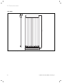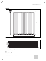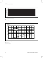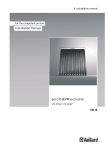
1
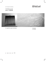
For the expert technician
Installation manual
auroTHERM
On-roof/flat roof installation
GB
VTK 570/2
VTK 1140/2
Contents
Contents
1
1.1
1.2
1.3
1.4
Notes on the documentation......................... 3
Other applicable documents ................................3
Storage of the documents ....................................3
Symbols used ...........................................................3
Applicability of the manual...................................3
2
2.1
2.2
Intended use .................................................... 3
Combination with other components ................3
Operational conditions ..........................................3
3
3.1
3.2
3.3
3.4
3.5
Safety instructions ........................................4
Technical Guidance.................................................4
Related documents .................................................4
Regulations for the prevention of accidents ...4
Lightning protection...............................................5
Frost protection.......................................................5
4
Before installation .......................................... 5
4.1
Safety instructions3 ...............................................5
4.2
Scope of delivery ....................................................6
4.2.1 On-roof mounting ...................................................6
4.2.2 Flat-roof mounting..................................................7
4.3
Assembling the collector array ...........................8
4.3.1 On-roof mounting ...................................................8
4.3.1.1 Collector arrangement, 1-row ..............................8
4.3.1.2 Collector arrangement, 2-row ........................... 10
4.3.1.3 Collector arrangement, 3-row .............................11
4.3.2 Flat-roof mounting.................................................13
4.4 Interconnection scheme ...................................... 14
4.5
Preparing the hydraulic connection ................. 16
4.5.1 On-roof mounting ................................................. 16
4.5.2 Flat-roof mounting................................................ 16
4.6
Required tools ........................................................ 16
5
On-roof mounting ...........................................16
5.1
Fitting the brackets ...............................................17
5.2.1 Bracket Type P (pantile) ..................................... 19
Fixing to the roof batten ................................................ 20
5.2.2 Bracket Type S (for high profile pantiles) .......21
5.2.3 Bracket Type S (Low profile for slate/ flat tiles)
21
5.2.3 Hanger bolt fixing kit ...........................................22
5.3
Fitting the collectors ............................................23
6
6.2
6.3
Flat-roof mounting ...................................... 28
Weighting and arrangement of the frames ... 28
Fitting the collectors ............................................32
7
Final operations ............................................37
8
Recycling and disposal ................................ 38
9
9.1
9.2
Vaillant Customer Service and warranty . 38
Vaillant warranty.................................................. 38
Vaillant service ..................................................... 38
2
10
Technical data ...............................................39
Notes on the documentation 1
Intended use 2
1
Notes on the documentation
The instructions below are intended to help you
throughout the entire documentation.
1.1
Other applicable documents
When assembling the tube collectors, pay attention to
all the installation instructions for the components and
assemblies within the solar installation. These instructions are included with the individual components of the
system and the additional components.We accept no liability for any damage caused by failure to observe
these instructions.
1.2
Storage of the documents
Please pass on this installation manual and all other applicable documents and auxiliary equipment to the plant
operator, whose responsibility it is to ensure the manuals and auxiliary equipment are available whenever required.
1.3
Symbols used
Please observe the safety instructions in this installation
manual for the installation of the collector!
Danger!
d Immediate
risk of serious injury or death!
Danger!
e Risk
of death from electric shock!
Danger!
H Danger
of burning and scalding!
a
Caution!
Potentially dangerous situations for the product and the environment!
h Note
Useful information and instructions.
• Symbol indicating the required action
2
Intended use
Vaillant auroTHERM tube collectors are built according
to the state of the art and recognised safety rules and
regulations.
Nevertheless, improper use may cause danger to life
and limb of the user or third parties and could impair
the operation of the unit and other objects.
The unit is not intended for use by persons (including
children) with reduced physical, sensory or mental capabilities, or lack of experience and/or knowledge,
unless they have been given supervision or instruction
concerning use of the unit by a person responsible for
their safety.
Children must be watched to ensure that they do not
play with the unit.
Vaillant auroTHERM tube collectors are used for solar
assisted hot water generation and where specially designed can provide additional heating such as pool heating.
The collectors may only be operated with Vaillant readymixed solar fluid. Passing heating water or hot water directly through the collectors is not permitted.
Any other use or use exceeding the above-mentioned
applications shall be considered as improper use. The
manufacturer/supplier shall not be responsible for any
damages resulting from such improper use. The user
alone bears the risk.
Intended use includes observance of the operating and
installation manuals and all other applicable documents,
as well as adherence to the maintenance and inspection
conditions.
Caution!
a Any
improper use is forbidden!
2.1
Combination with other components
Vaillant tube collectors should be combined only with
Vaillant components (fixing, connections) and system
components.
The use of other components or system components
shall be considered as improper use. We accept no liability.
1.4
Applicability of the manual
This installation manual applies exclusively to tube collectors with the following part numbers:
2.2
Collector type
Part number
Caution!
a The
roof may collapse!
VTK 570/2
0010002227
VTK 1140/2
0010002228
Operational conditions
Mount the tube collectors only on roofs with an
adequate load-bearing capacity.
If necessary, call a technician.
Table 1.1 Collector types and article numbers
Please see the identification plate on the upper edge of
the collector for the part number of the tube collector.
Installation manual auroTHERM 0020077994_00
GB
3
2 Intended use
3 Safety instructions
On-roof mounting:
The tube collectors can be mounted at an angle of
15° – 75°.
An installation angle of less than 15° is not permissible.
Flat roof installation:
The tube collectors can be installed on flat roof frames
in the as-delivered condition with an angle of 30°, 45°
or 60°.
An installation angle of less than 15° is not permissible.
3
Safety instructions
The following safety instructions, technical rules and accident prevention regulations must be observed when
installing the flat collectors.
Danger!
d Risk
of death from falls and falling objects!
Observe the national regulations for working at
heights.
Danger!
H Danger
of burning and scalding!
In case of solar irradiation inside the units, collectors can reach 300 °C. Remove the sun protection film installed at the factory only after
the solar energy system has been started up.
Danger!
H Danger
of burning and scalding!
In case of solar irradiation inside the units, collectors can reach 300 °C.
Do not perform maintenance work under direct
sunlight.
Caution!
a Collector
damage!
A qualified engineer is required to install tube
collectors in accordance with this installation
manual.
The installation should thus be performed only
if a qualified engineer is available.
3.1
Technical Guidance
The system must be installed in accordance with all relevant and applicable national regulations, and must be
installed to suit site conditions.
Observe all national regulations, including:
- Working at Heights Regulations 2005
- Health and Safety at Work Act 1974
- Electricity at Work Regulations 1989
- IEE Wiring Regulations BS 7671
- Lightning protection requirements
- Equipotential bonding of electrical installations.
4
3.2
Related documents
Designers and installers should refer to current information and standards. A useful reference would be the energy saving trust document CE 131 (this is downloadable
from their web site at www.est.org.uk/housingbuildings)
which lists relevant standards and other documents that
you might refer to. This includes but is not limited to the
following;
Solar Standards
BS 7431, BS 6785: 1986, BS EN 12975 / 6 (Pt1-2), prEN
12977 (1-2-3) BS EN ISO 9488
The installation of the solar system must be in accordance with the relevant requirements of Health and Safety Document No. 635 (The Electricity at Work Regulations 1989), BS7671 (IEE Wiring Regulations) and the
Water Supply (Water Fitting) Regulations 1999, or The
Water Bylaws 2000 (Scotland). It should also
be in accordance with the relevant requirements of the
Local Authority, Building Regulations, The Building Regulations (Scotland), The Building Regulations
(Northern Ireland) and the relevant recommendations of
the following British Standards:
- BS EN 806: Specification for installations inside buildings conveying water for human consumption
– BS 6700: Services supplying water for domestic use
within buildings and their curtilages.
- BS. 5449 Forced circulation hot water central heating
systems for domestic premises.
Note: only up to 45 kW.
- BS. 6880 Low temperature hot water heating systems
of output greater than 45 kW.
Part 1 Fundamental and design considerations.
Part 2 Selection of equipment.
Part 3 Installation, commissioning and maintenance.
– BS 6114: Expansion vessels using an internal diaphragm for unvented hot water supply systems
- BS. 4814 Specification for: Expansion vessels using an
internal diaphragm, for sealed hot water heating systems.
Unvented hot water systems must comply with building
regulation G section 3.
3.3
Regulations for the prevention of accidents
When carrying out works such as solar installation work
it is necessary to do so in a safe and workman like manner, taking due care of any aspects of the works that
could result in injuries to person in or about the building
as well as workers, passers by and the general public at
large. To that end these works must conform, but
not be limited to, the current regulations in force such
as the following
- Health and Safety at Work act 1974
- Work at Height Regulations 2005.
- Electricity at Work Regulations 1989
- All necessary Building Regulations.
Work should be preceded by a risk assessment covering
all aspects of health and safety risks, or training requirements that can reasonably be foreseen to be
Installation manual auroTHERM 0020077994_00
Safety instructions 3
Before installation 4
associated with the work. All scaffolding in the UK, other
than prefabricated (zip-up) scaffold towers, must be designed and constructed by a vetted contractor, and
have suitable kick boards, hand rails and where appropriate netting. Areas around the scaffolding should be
zoned off and marked with suitable warning signs to a
suitable distance to protect persons from falling objects.
Workers should have available and use personal protective equipment as necessary. This would include equipment such as fall protection systems, safety gloves,
goggles, dust masks as well as any specialised equipment that may be in use such as lifting and handling
equipment.
The completed works shall comply with all necessary
BS EN Standards and Codes of practice as well as Building control or planning requirements and be confirmed
where necessary by notification to building control or
the appropriate competence based notification body.
3.4
a
3.5
4
Before installation
4.1
Safety instructions3
Please note the following instructions before and during
installation:
Danger!
d Risk
of death from falls and falling objects!
Observe the national regulations for working at
heights.
Wear the Vaillant safety belt (article number
302066).
Danger!
H Danger
of burning and scalding!
In case of solar irradiation inside the units, collectors can reach 300 °C. Remove the sun protection film installed at the factory only after
the solar energy system has been started up.
Lightning protection
Caution!
Damage from lightning!
If the installation height is more than 20 m or
if the collectors are projected above the roof
ridge, electro-conductive components must be
connected to a lightning protection device!
Frost protection
Caution!
a Damage
due to frost!
Never fill or flush the collector with water. Only
fill and flush the collector with Vaillant readymixed solar fluid.
Check the solar fluid regularly with an antifreeze tester.
Installation manual auroTHERM 0020077994_00
Caution!
a Collectors
may be damaged by incorrect stor-
age!
Always store the collectors in a dry place and
protected from the elements.
Caution!
System error function due to air bubbles!
To fill the system, use the fill trolley (article
number 0020042548) to avoid air bubbles.
Use the manual air vent installed on the collector field.
Alternatively, install the Vaillant Solar automatic air vent (article number 302019) in the
highest point of the system or the automatic
de-aerator (article number 302418) in the solar
circuit.
Observe the relevant installation and operating
manual.
GB
5
4 Before installation
4.2
Scope of delivery
• Check the mounting kit for completeness based on the
illustrations and bills of materials.
4.2.1
On-roof mounting
12
1
11
10
9
2
8
7
6
5
3
4
Fig. 4.1 On-roof mounting kit
Pos. Description
Quantity Article number (kit)
1
Rail kit VTK 1140/2
2
0020076781
2
Rail kit VTK 570/2
2
0020076780
3
Tube collector VTK 570/2
1
0010002227
4
Tube collector VTK1140/2
1
0010002228
1
0020076785
1
0020076779
1
7
Connecting kit VTK (basic module)
- Compression fitting 15 mm x 3/4'' external thread DN16
- Insulation EPDM 13 x 28, 60 mm, split
Connecting kit VTK (expansion module)
- Rail joining pieces
- Double nipple 15 x 15 mm
- Insulation Armeflex HT, 25 x 20 mm, 45lg
- Cover clip
Valve, 2-way VTK for parallel interconnection
8
Bracket type S
4
9
Bracket type S flat
4
10
Bracket type P (for pantile)
4
11
Long base (accessory, not available in every country)
4
0020076784
0020067275 (for mounting side-by-side)
0020067276 (for mounting on top of one another)
0020080145 (for mounting side-by-side)
0020080147 (for mounting on top of one another)
0020067273 (for mounting side-by-side)
0020067274 (for mounting on top of one another)
0020080177
12
Stair bolt mounting kit
4
0020067277
5
6
Table 4.1 On-roof mounting bill of materials
6
Installation manual auroTHERM 0020077994_00
Before installation 4
4.2.2 Flat-roof mounting
1
9
2
8
3
7
4
6
5
Fig. 4.2 Flat roof mounting kit
Pos. Description
Quantity Article number (kit)
1
Rail kit VTK 1140/2
2
0020076781
2
Rail kit VTK 570/2
2
0020076780
3
Open air installation, VTK
1
0020076778
4
Gravel tray kit
2
3
0020059904 (2 pcs.)
0020059905 (3 pcs.)
5
Tube collector VTK 570/2
1
0010002227
6
Tube collector VTK1140/2
1
0010002228
7
Valve, 2-way VTK for parallel interconnection
1
0020076784
8
Connecting kit VTK (basic module)
1
0020076785
9
Connecting kit VTK (expansion module)
1
0020076779
Table 4.2 Flat roof installation bill of materials
Installation manual auroTHERM 0020077994_00
GB
7
4 Before installation
4.3
Assembling the collector array
The following tables list the required components according to the type of installation.
4.3.1 On-roof mounting
When mounted on the roof, Vaillant tube collectors can
be arranged above one another in up to 3 rows.
4.3.1.1 Collector arrangement, 1-row
Fig. 4.3 Installation kit for single row on-roof mounting
(here: VTK 570/2)
Number of collectors
1
2
3
4
5
6
7
Connecting kit VTK (basic module)
Part No. 0020076785
Bracket kit Type S flat
Part No. 0020080145
Required quantity
VTK 570/2
Bracket kit Type S
(shingle)
Part No. 0020067275
9
10
11
12
13
14
11)
Connecting kit VTK (expansion module)
Part No. 0020076779
Bracket kit Type P
(pantile)
Part No. 0020067273
8
-
1
2
3
4
5
6
7
8
9
10
11
12
13
12)
22)
32)
42)
52)
62)
72)
82)
92)
102)
112)
122)
132)
142)
1
2
3
4
5
6
7
8
9
10
11
12
13
14
Bracket kit (hanger
bolt)
Part No. 0020067277
Rail kit (2), VTK 570/2
Part No. 0020076780
1) 1 each per row
2) applies up to 700 m above sea level
Table 4.3 Components for single row on-roof mounting
8
Installation manual auroTHERM 0020077994_00
Before installation 4
Number of collectors
1
2
3
Connecting kit VTK (basic module)
Part No. 0020076785
5
6
7
11)
Connecting kit VTK (expansion module)
Part No. 0020076779
1
2
3
4
5
6
12)
22)
32)
42)
52)
62)
72)
1
2
3
4
5
6
7
Number of collectors VTK 1140/2
1
2
3
4
5
6
Number of collectors VTK 570/2
1
1
1
1
1
1
Bracket kit Type S
Part No. 0020067275
Bracket kit Type S flat
Part No. 0020080145
Required quantity
-
Bracket kit Type P (pantile)
Part No. 0020067273
VTK 1140/2
4
Bracket kit (hanger bolt)
Part No. 0020067277
Rail kit (2), VTK 1140/2
Part No. 0020076781
Connecting kit VTK (basic module)
Part No. 0020076785
11)
1
2
3
4
5
6
22)
32)
42)
52)
62)
72)
1
2
3
4
5
6
Bracket kit Type P
(pantile)
Part No. 0020067273
Bracket kit Type S
Part No. 0020067275
Bracket kit Type S flat
Part No. 0020080145
Required quantity
VTK 1140/2 + VTK 570/2
Connecting kit VTK (expansion module)
Part No. 0020076779
Bracket kit (hanger bolt)
Part No. 0020067277
Rail kit (2), VTK 1140/2
Part No. 0020076781
Rail kit (2), VTK 570/2
Part No. 0020076780
1
1) 1 each per row
2) applies up to 700 m above sea level
Table 4.3 Components for single row on-roof mounting (continued)
Installation manual auroTHERM 0020077994_00
GB
9
4 Before installation
4.3.1.2 Collector arrangement, 2-row
A
B
A
Fig. 4.4 Installation kit for 2-row on-roof mounting
(here: VTK 570/2)
Number of collectors per row
1
2
3
4
5
6
7
Number of rows
Connecting kit VTK (basic module)
Part No. 0020076785
Connecting kit VTK (expansion module)
Part No. 0020076779
Bracket kit Type P
(pantile)
Part No. 0020067273
10
11
12
13
14
21)
a
Bracket kit Type S flat
Part No. 0020080145
Bracket kit Type P
(pantile)
Part No. 0020067274
9
-
2
4
6
8
10
12
14
16
18
20
22
24
26
12)
22)
32)
42)
52)
62)
72)
82)
92)
102)
112)
122)
132)
142)
12)
22)
32)
42)
52)
62)
72)
82)
92)
102)
112)
122)
132)
142)
2
4
6
8
10
12
14
16
18
20
22
24
26
28
Required quantity
VTK 570/2
Bracket kit Type S
Part No. 0020067275
8
2
B
Bracket kit Type S
Part No. 0020067276
Bracket kit Type S flat
Part No. 0020080147
Rail kit (2),
VTK 570/2
Part No. 0020076780
1) when the connection between the rows is also flat-sealing
2) applies up to 700 m above sea level
Table 4.4 Components for 2-row on-roof mounting
10
Installation manual auroTHERM 0020077994_00
Before installation 4
Number of collectors per row
1
2
3
Number of rows
4
5
6
7
2
Connecting kit VTK (basic module)
Part No. 0020076785
21)
Connecting kit VTK (expansion module)
Part No. 0020076779
-
2
4
6
8
10
12
12)
22)
32)
42)
52)
62)
72)
12)
22)
32)
42)
52)
62)
72)
2
4
6
8
10
12
14
Bracket kit Type P (pantile)
Part No. 0020067273
Bracket kit Type S
Part No. 0020067275
Required quantity
VTK 1140/2
a
Bracket kit Type S flat
Part No. 0020080145
Bracket kit, Type P
(pantile) Part No. 0020067274
B
Bracket kit Type S
Part No. 0020067276
Bracket kit Type S flat
Part No. 0020080147
Rail kit (2), VTK 1140/2, Part No. 0020076781
1) when the connection between the rows is also flat-sealing
2) applies up to 700 m above sea level
Table 4.4 Components for 2-row on-roof mounting (continued)
4.3.1.3 Collector arrangement, 3-row
A
B
B
A
Fig. 4.5 Installation kit for 3-row on-roof mounting
(here: VTK 570/2)
Installation manual auroTHERM 0020077994_00
GB
11
4 Before installation
Number of collectors per row
1
2
3
4
5
6
7
Number of rows
11
12
13
14
-
3
6
9
12
15
18
21
24
27
30
33
36
39
12)
22)
32)
42)
52)
62)
72)
82)
92)
102)
112)
122)
132)
142)
22)
42)
62)
82)
102)
122)
142)
162)
182)
202)
222)
242)
262)
282)
3
6
9
12
15
18
21
24
27
30
33
36
39
42
1
2
3
4
5
6
7
Required quantity
VTK 570/2
a
Bracket kit Type S flat
Part No. 0020080145
Bracket kit Type P
(pantile)
Part No. 0020067274
10
31)
Connecting kit VTK (expansion module)
Part No. 0020076779
Bracket kit Type S
Part No. 0020067275
9
3
Connecting kit VTK (basic module)
Part No. 0020076785
Bracket kit Type P
(pantile)
Part No. 0020067273
8
B
Bracket kit Type S
Part No. 0020067276
Bracket kit Type S flat
Part No. 0020080147
Rail kit (2), VTK 570/2
Part No. 0020076780
Number of collectors per row
Number of rows
3
Connecting kit VTK (basic module)
Part No. 0020076785
31)
Connecting kit VTK (expansion module)
Part No. 0020076779
Bracket kit Type P
(pantile)
Part No. 0020067273
a
Bracket kit Type S flat
Part No. 0020080145
Bracket kit, Type P
(pantile)
Part No. 0020067274
3
6
9
12
15
18
12)
22)
32)
42)
52)
62)
72)
22)
42)
62)
82)
102)
122)
142)
3
6
9
12
15
18
21
Required quantity
VTK 1140/2
Bracket kit Type S
Part No. 0020067275
-
B
Bracket kit Type S
Part No. 0020067276
Bracket kit Type S flat
Part No. 0020080147
Rail kit (2), VTK 1140/2
Part No. 0020076781
1) when the connections between the rows are made by flat seal connection.
2) applies up to 700 m above sea level
Table 4.5 Components for 3-row on-roof mounting
12
Installation manual auroTHERM 0020077994_00
Before installation 4
4.3.2
Flat-roof mounting
Number of collectors
1
2
3
4
5
6
7
11
12
13
14
1
2
3
4
5
6
7
8
9
10
11
12
13
Mounting kit for open-air installation on a
flat roof
Part No. 0020076778
2
3
4
5
6
7
8
9
10
11
12
13
14
15
Gravel trays required
4
6
8
10
12
14
16
18
20
22
24
26
28
30
Gravel tray kit (2 pcs.)
Part No. 0020059904
2
-
1
2
-
1
2
-
1
2
-
1
2
-
Gravel tray kit (3 pcs.)
Part No. 0020059905
-
2
2
2
4
4
4
6
6
6
8
8
8
10
1
2
3
4
5
6
7
8
9
10
11
12
13
14
Connecting kit VTK (expansion module)
Part No. 0020076779
Required quantity
-
Connecting kit VTK (basic module)
Part No. 0020076785
VTK 1140/2
10
Connecting kit VTK (expansion module)
Part No. 0020076779
Rail kit (2), VTK 570/2
Part No. 0020076780
VTK 1140/2 + VTK 570/2
9
11)
11)
-
1
2
3
4
5
6
Mounting kit for open-air installation on a
flat roof
Part No. 0020076778
2
3
4
5
6
7
8
Gravel trays required
8
12
16
20
24
28
32
Gravel tray (2 pcs.)
Part No. 0020059904
1
-
2
1
-
2
1
Gravel tray (3 pcs.)
Part No. 0020059905
2
4
4
6
8
8
10
Rail kit (2) aluminium, VTK 1140/2
Part No. 0020076781
1
2
3
4
5
6
7
Number of collectors VTK 1140/2
-
1
2
3
4
5
6
Number of collectors VTK 570/2
-
1
1
1
1
1
1
Connecting kit VTK (basic module)
Part No. 0020076785
-
Connecting kit VTK (expansion module)
Part No. 0020076779
-
1
2
3
4
5
6
-
3
4
5
6
7
8
-
8
12
16
20
24
28
-
1
-
2
1
-
2
-
2
4
4
6
8
8
Rail kit (2), VTK 1140/2
Part No. 0020076781
-
1
2
3
4
5
6
Rail kit (2), VTK 570/2
Part No. 0020076780
-
Mounting kit for open-air installation on a
flat roof Part No. 0020076778
Gravel trays required
Gravel tray kit (2 pcs.)
Part No. 0020059904
Gravel tray kit (3 pcs.)
Part No. 0020059905
Required quantity
VTK 570/2
Connecting kit VTK (basic module)
Part No. 0020076785
8
11)
1
1) 1 each per collector array
Table 4.6 Flat roof installation components
Installation manual auroTHERM 0020077994_00
GB
13
4 Before installation
4.4
Interconnection scheme
h Note
Observe the planning information when dimensioning the array volume flow.
Furthermore, observe the following rules:
• Connect a maximum of 14x VTK 570/2
(corresponding to an aperture area of 14
m2) in series.
max. 14
Fig. 4.6 Series connection VTK 570/2
• Connect a maximum of 7x VTK 1140/2
(corresponding to an aperture area of 14
m2) in series.
max. 7
Fig. 4.7 Series connection VTK 1140/2
• For aperture areas greater than 14 m2, you
must configure several collector arrays in
parallel and connect them hydraulically in
parallel.
• Always connect as many collectors as possible in series.
h Note
You should only connect the collec-
tor arrays in parallel if the aperture
area is greater than 7 m2 (corresponding to 7x VTK 570/2 or 3x 1140/2
+ 1x VTK 570/2).
Fig. 4.8 Parallel connection (here VTK 570/2)
14
Installation manual auroTHERM 0020077994_00
Before installation 4
When collector arrays are connected in parallel, each individual array must have the
same aperture area.
Fig. 4.9 Sizes of the individual arrays
Caution!
a Danger
of air locks!
If 3 or more collector arrays are connected in parallel, a stop valve must
be fitted in the collector supply line
(hot side) of each individual array.
These will be used for venting the individual arrays during commissioning. Only use the Vaillant stop
valve, Part No. 0020076784
Fig. 4.10 Stop valve in the collector supply line
Installation manual auroTHERM 0020077994_00
Caution!
a Danger
of damage to the material as
a result of incorrect assembly!
With the valve closed or wrong valve
positioning, damaging of the collector
due to excessive pressure will be
possible. Never mount the stop valve
in the collector return. The stop
valve must be open during system
operation.
GB
15
4 Before installation
5 On-roof mounting
4.5
Preparing the hydraulic connection
4.5.1
On-roof mounting
Fig. 4.12 Assembly tools: spirit level, cordless screwdriver,
Torx bit (TX30, supplied), allen key 5mm,
socket/combination wrench (13 mm), hammer,
measuring tape / folding rule
Fig 4.11 Passing the pipe through the sarking membrane
5
If there is a sarking membrane, proceed as follows:
• Make a v-shaped cut in the sarking membrane.
• Fold the upper, wider flap on to the roof batten above,
and the lower, narrower flap on to the roof batten
below.
• Fix the sarking membrane tight to the roof batten.
This ensures that the dampness flows away to the
side.
With on-roof mounting, the tube collectors are fastened
to horizontal mounting rails quickly and reliably with attachment clips. To ensure a good adaptation to the different roofings, four different brackets are available:
- Type P for standard concrete tiles (e.g. pantile),
- Type S for extremely high protruding tiles (e.g. Mediterranean clay tiles)
- Type S flat (low profile) for flat tiles or slate roofs.
- Stair bolt mounting kit for universal fixing (e.g. corrugated slabs, sheet with trapezoidal corrugations, shingles).
• With board-clad roofs, cut out a hole with a padsaw.
• Work the roofing felt as described for the sarking
membrane.
4.5.2 Flat-roof mounting
Caution!
a The
roof skin can break and cause leaks!
When installing the roof sealing surfaces, make
sure the roof skin is adequately protected.
• Place large protection mats under the system.
• If the frame is screwed directly, check the sealing of
the building shell.
4.6
Required tools
• Have the following tools ready for assembling the
tube collectors.
On-roof mounting
Caution!
a Risk
of corrosion!
On roofs made of metals more noble than aluminium (e.g. on copper roofs) galvanic corrosion
can occur at the anchor points, whereby the attachment of the collectors is no longer guaranteed. Ensure that the metals are separated by
suitable underlays.
When mounted on the roof, the Vaillant tube collectors
in the collector array can be arranged side-by-side or
above each other.
In general, the installation steps and instructions described in this manual are applicable to all collector
arrangements.
Any different installation steps are clearly pointed out:
For collectors arranged side-by-side
For collectors arranged above each other
When arranging the collectors, take note in each case of
the possible interconnection schemes in Section 4.4.
16
Installation manual auroTHERM 0020077994_00
On-roof mounting 5
5.1
Fitting the brackets
For collectors arranged side-by-side
• Mount the anchors for the mounting rails at the following distances:
h Note
During final fixing the pre-assembly dimension
A is reduced by approx. 20 - 25 mm. Take care
that there is adequate clearance on the anchors, therefore.
B
C
D
707
2
1414
3
2121
4
2828
5
3535
50 - 100
6
7
8
9
11
12
507 - 607
1
10
4242
4949
5656
6363
7777
9898
1
1397
2
2794
5
997 - 1197
9191
14
4
A
8484
13
3
A
7070
100 - 200
VTK 1140/2
A*
1663 / 1638
VTK 570/2
Number of
collectors
A
4191
5588
6985
6
8382
7
9779
* Pre-assembly dimension / Finished dimension
During final fixing of the collectors, the pre-assembly dimension
is reduced by approx. 20 - 25 mm.
Table 5.1 Spacings when arranging collectors side-by-side
[in mm]
Installation manual auroTHERM 0020077994_00
C
B
B B
B
D
Fig. 5.1 Spacings when arranging collectors side-by-side
GB
17
5 On-roof mounting
For collectors arranged on top of each other
• Mount the anchors for the mounting rails at the following distances:
Note
h During final fixing the pre-assembly dimension
A is reduced by approx. 20 - 25 mm. Take care
that there is adequate clearance on the anchors, therefore.
A*
B
C
D
1
707
2
1414
5
3535
6
4242
7
8
9
507 - 607
2828
50 - 100
2121
4
1663 / 1638
3
E
3322
5006
6363
11
7777
12
8484
13
9191
14
9898
1
1397
2
2794
3
4191
997 - 1197
E
100 - 200
5
E
3 rows
5656
7070
4
E
2 rows
4949
10
1663 / 1638
VTK 1140/2
VTK 570/2
Number of
collectors
5588
A
A
A
3322
E
C
5006
6985
6
8382
7
9779
* Pre-assembly dimension / Finished dimension
During final fixing of the collectors, the pre-assembly dimension
is reduced by approx. 20 - 25 mm.
B
B B
D
B
Fig. 5.2 Spacings when arranging collectors on top of each
other
Table 5.2 Spacings when arranging collectors on top of each
other [in mm]
18
Installation manual auroTHERM 0020077994_00
On-roof mounting 5
5.2.1
Bracket Type P (pantile)
1
2
A
3
2
B
5 mm
1
Fig. 5.3 Bracket type P
Key
1 Lower bracket
2 Upper bracket
3 Central bracket
The bracket type P can be fixed to the rafters
(Pos. A) or by use of the long rear plate set
0020080177 can be offset to suit tile profile.
Fixing to rafters
5
A
3
6
2
1
4
B
Fig. 5.4 Fixing to rafters
1. Uncover the rafters where needed. For distances
please see Tab. 5.1 and 5.2.
2. Position the bracket. Take note of the correct positions of the upper, central and lower brackets
(see Fig. 5.3).
3. Loosen the upper bolt with the socket/combination
wrench (13 mm) until the height of the bracket can be
adjusted.
4. Position the bracket at the same height of the pantiles, so that the upper part of the anchor is on the
roofing, and tighten the bolt with the socket/combination wrench (13 mm).
Installation manual auroTHERM 0020077994_00
5. Screw the bracket to the rafters with the 3 supplied
bolts.
6. Slide the pantiles back to the original position.
If necessary, adapt the water gutter on the lower (A)
or upper side (B) of the pantile with a hammer, or
suitable disk cutter, until the pantiles are tight.
Danger!
d Risk
of injury!
Always wear suitable eye protection and all
necessary personal protective equipment and
ensure the area of work is safe with regard to
other persons.
GB
19
5 On-roof mounting
h Note
With some roof covering it may be necessary to
offset the roof bracket to the left or right of
the rafter, to do this use the accessory:
Part No. 0020080177 (not available in every
country). Observe the appropriate installation
manual.
Fixing to the roof batten
Caution!
a Only
acceptable if roof and battens have been
inspected by a competent roofing contractor /
designer.
Before installation on the roof batten, check
the load capacity of the roof batten!
If necessary, replace the roof batten or provide
additional timber bearers.
Also ensure battens are fixed securely (screw
to rafter each side of brackets).
2
4
3
1
5
6
Fig. 5.5 Fixing to the roof batten
1. Slide upward one or two pantiles above the roof batten.
For distances please see Tab. 5.1 and 5.2.
2. Loosen the upper bolt with the socket/combination
wrench (13 mm) until the height of the bracket can be
adjusted.
3. Hook the bracket to the roof batten. Take note of the
correct positions of the upper, central and lower
brackets when doing this (see Fig. 5.3).
20
4. Position the bracket at the same height of the pantiles. The upper part is on the roofing, the lower part
is pressed tight against the roof batten from the bottom.
Take care anchor is tightly fixed and pre-tensioned on
the roof batten (toothing engaged).
5. Tighten the bolt with the socket/combination wrench
(13 mm).
6. Slide the pantiles back to the original position. If necessary, adapt the water gutter on the lower side of
the pantile with a hammer, until the pantiles are tight
Installation manual auroTHERM 0020077994_00
On-roof mounting 5
5.2.2
Bracket Type S (for high profile pantiles)
Caution!
a Before
installation on the roof batten, check
the load capacity of the roof batten!
If necessary, replace the roof batten.
1
3
2
4
Fig. 5.6 Fixing the bracket type S
1. Uncover the rafters or the roof batten where needed.
For distances please see Tab. 5.1 and 5.2.
2. Position the bracket. Take note of the correct positions of the upper, central and lower brackets
(see Fig. 5.3).
5.2.3
3. Screw the bracket to the rafters/roof batten with the
3 supplied bolts.
4. Slide the pantiles back to the original position.
Bracket Type S (Low profile for slate/ flat
tiles)
Caution!
a Only
acceptable if roof and battens have been
inspected by a competent roofing contractor /
designer.
Before installation on the roof batten, check
the load capacity of the roof batten!
If necessary, replace the roof batten or provide
additional timber bearers.
Also ensure battens are fixed securely (screw
to rafter each side of brackets).
1
3
2
4
Fig. 5.7 Fixing the bracket type S flat
1. Uncover the rafters or the roof batten where needed.
For distances please see Tab. 5.1 and 5.2.
2. Position the bracket. Take note of the correct positions of the upper, central and lower brackets
(see Fig. 5.3).
Installation manual auroTHERM 0020077994_00
3. Screw the bracket to the rafters/roof batten with the
3 supplied bolts.
4. Slide the pantiles back to the original position.
GB
21
5 On-roof mounting
5.2.3
Hanger bolt fixing kit
Caution!
a Before
installation check the load-bearing capacity of the wooden substructure!
If necessary, strengthen it.
Only for use on roof structures with timbers
large enough to accept stair bolt.
1
3
6
2
5
4
Fig. 5.8 Fixing with stair bolt
1. Bore a hole in the roof covering in the corresponding
position. For distances please see Tab. 5.1 and 5.2.
2. Tighten the stair bolt to the rafters through the pantile.
3. Screw the lower nut against the roof covering, and
tighten it until the seal sufficiently seals the opening.
22
4. Position the central nut so that after inserting the anchor upper part the front contact area is on the roofing. Take note of the correct positions of the upper,
central and lower brackets when doing this
(see Fig. 5.3).
5. Screw the second nut and tighten it (17 mm).
6. Cut off the threaded bolt directly above the nut.
Deburr the interface.
Installation manual auroTHERM 0020077994_00
On-roof mounting 5
5.3
Fitting the collectors
• Fix the horizontal mounting rails with the
frame clamping elements on the brackets.
h Note
For the vertical spacing between the
brackets please see Tables 5.1 and
5.2.
h Note
For a better visual appearance, position the lower rail as low as possible
on the bracket.
Fig. 5.9 Fixing the mounting rails
• Insert the connecting elements into the
mounting rails by the side, until they lock
into place.
• Join the mounting rails and fix them with
the clamping elements on the brackets
(see Fig. 5.8).
Fig. 5.10 Joining the mounting rails
• Make sure that the mounting rails are fixed
in horizontal position.
• Compensate any difference in height by
moving the clamping elements.
• Pull the clamping element upward, now it
can be moved and it engages again when
released.
2
1
Fig. 5.11 Balancing the mounting rails
Installation manual auroTHERM 0020077994_00
GB
23
5 On-roof mounting
• Place the collector with the lower edge on
the mounting rail and hook it to the clamping elements.
• Make sure that the upper part (1) of the
clamping element is above the collector
rail.
• Tighten the clamping elements of the lower
mounting rail with the socket/combination
wrench (13 mm).
1
Caution!
a After
tightening the clamping ele-
ments, make sure the tension is correct by shaking the upper part of the
clamping element. If it can be moved,
retighten the nut.
Fig. 5.12 Hooking the collector
• Lift the film at the edges of the collector.
This will facilitate pulling off the film later,
after commissioning.
1
Danger!
H Danger
of burning!
In case of solar irradiation inside the
units, collectors can reach
300 °C. Remove the sun protection
film installed at the factory only
after the solar energy system has
been started up.
Fig. 5.13 Peeling the film from the edges of the collector
• Remove the carrying straps.
Fig. 5.14 Removing the carrying straps
24
Installation manual auroTHERM 0020077994_00
On-roof mounting 5
• Place the next collector on the lower
mounting rail.
• Make sure that the upper part (1) of the
clamping element is above the collector
rail.
• Tighten the lower clamping elements on
the collector.
• Slide the upper mounting rails and clamping elements little by little from the top
against the collector.
1
Fig. 5.15 Mounting other collectors
1
A
• Couple the double nipple (A) (from the VTK
expansion module connecting kit, Part No.
0020076779) to the union nut (B) on the
first collector.
• Push the collectors together.
B
2
Fig. 5.16 Joining the collectors
Caution!
a Danger
of damage to the collector as
a result of incorrect assembly!
To prevent damage when tightening
the compression fitting, always use a
second spanner to provide a counter
force.
• Tighten the two union nuts on the double
nipple.
Fig. 5.17 Tightening the compression fitting
1
• Slide the upper mounting rails towards the
collector.
• Take care that the upper parts of the clamping elements are over the rails on the
collectors.
Fig. 5.18 Positioning the upper mounting rail
Installation manual auroTHERM 0020077994_00
GB
25
5 On-roof mounting
2
For collectors arranged on top of
each other
3
1
• Slide the central mounting rail flush with
the lower collector (1).
• Make sure that the hook of the clamping
element (3) is above the edge of the collector.
• Fix the mounting rail (2) for the next row
of collectors to the clamping element.
Fig. 5.19 Central mounting rail for 2 or 3 rows of collectors
1
3
For collectors arranged on top of
each other
• Place the upper collector (1) in the central
mounting rail (2).
• Screw the clamping elements (3) on the
central rail tight.
• Fit the second row of collectors as described above.
2
Fig. 5.20 Central mounting rail for 2 or 3 rows of collectors
26
Installation manual auroTHERM 0020077994_00
On-roof mounting 5
• For systems with collector sensors: Plug
the collector sensor into the opening provided on the flow side of the collector (hot
side).
With several rows of collectors:
• Connect the rows of collectors in accordance with the interconnection schemes
(cf. Section 4.4).
In general it is possible to attach the
h Note
collector sensor to the left or the
right side of the collector array, as
the collectors have a corresponding
opening on each side.
Ensure VR11 sensors are fitted to the
hot side of the collector array.
Fig. 5.21 Fitting the hydraulic connections
Caution!
of damage to the collector as
a Danger
a result of incorrect assembly!
To prevent damage when tightening
the compression fitting, always use a
second spanner to provide a counter
force.
• Connect the collector supply and return to
the system with the connection pipes.
• To do this, connect the compression fitting
(from the VTK basic module connecting kit,
Part No. 0020076785) to the collector and
connect this to the connecting pipe.
• If necessary check all connections for
leaks.
2
1
3
After commissioning:
• Insulate the hydraulic connections with the
Armeflex insulation (1) (from the VTK expansion module connecting kit, Part No.
0020076779).
• Cover the insulation with the cover clip (2)
(from the VTK expansion module connecting kit, Part No. 0020076779).
• Insulate the hydraulic system connections
with the EPDM insulation (3) (from the VTK
expansion module connecting kit, Part No.
0020076779).
Fig. 5.22 Insulating the hydraulic connections
Installation manual auroTHERM 0020077994_00
GB
27
6 Flat-roof mounting
6
Flat-roof mounting
With flat roof installation, the tube collectors are fastened to frames.
The flat roof frames allow for a flexible installation with
an angle of 30 °, 45 ° or 60 °.
Also note that the height of the mounting rails is variable, in order to compensate for small floor irregularities.
6.2
Weighting and arrangement of the frames
First of all, define the necessary load of the frames
based on Tab. 6.1.
Load [kg/collector]
Height above ground Height
[m] above ground
CollectorAngle of attack
angle
0-10
0-10 m
30°
45°
60°
70
100
125
225
30°
45°
60°
159
276
10-18
10-18 m
80
115
140
252
178
309
18-25
18-25 m
90
130
155
279
197
342
Table 6.1 Flat roof installation load
Caution!
a The
roof may collapse!
Before installation, check the maximum roof
load!
If necessary, contact a specialist roofing designer/contractor before proceeding.
Consider if the frame can be bolted to the
structure as opposed to weighting.
28
a Caution!
For determining the installation location, keep
a distance of 1 m from the roof edge! A different distance causes high wind loads.
Installation manual auroTHERM 0020077994_00
Flat-roof mounting 6
For the required space and the distances between
frames please see Tables 6.2 to 6.4.
45°
(42.5°)
60°
(59.5°)
B
B
B
F
F
C
3289
6
3996
7
4703
8
5410
9
6117
10
6824
11
7531
12
8238
13
8945
14
9652
1) Installation angle 30°, 45° oder 60°
2) Solar altitude of 20° (winter sun)
3) Dimension A may vary in conjunction with dimensions D and E by
±30 mm
4) ±5 mm
D
E
707
5
2460
2582
4830 2)
4
B
1757
1875
3940 2)
3
1432
1168
2950 2)
560
2
A
F
4)
1
D
±30
-
30°
(28.5°)
584
A3)
1072
Number of
collectors
-
VTK 570/2 [distances in mm]
A
α
1)
F
C
α
1)
C
Table 6.2 Dimensions for VTK 570/2 [in mm]
Installation manual auroTHERM 0020077994_00
GB
29
6 Flat-roof mounting
VTK 1140/2 [distances in mm]
B
E
D
A
α1)
F
α1)
C
C
Number of
collectors
A3)
1
11704)
2
2548
3
3945
4
5342
5
6739
6
8136
7
9533
30°
B
1072
45°
F
29502)
B
1432
60°
F
39402)
B
1757
F
48302)
C
2460
D
±30
A
-
-
1274
1397
1) Angle of attack 30°, 45° or 60°
2) Solar altitude of 20° (winter sun)
3) Dimension A may vary in conjunction with dimensions D and E by ±30 mm
4) ±5 mm
Table 6.3 Dimensions for VTK 1140/2 [in mm]
30
Installation manual auroTHERM 0020077994_00
Flat-roof mounting 6
VTK 1140/2 and VTK 570/2 in combination [distances in mm]
B
D
E
G
A
VTK 1140/2
α1)
F
α1)
C
C
Number of
collectors
30°
A3)
VTK
570/2
VTK
1140/2
1
1
11704)
1
2
2548
1
3
3945
1
4
5342
1
5
6739
1
6
8136
VTK 570/2
45°
60°
B
F
B
F
B
F
1072
29502)
1432
39402)
1757
48302)
C
D
±30
A
G
2460
584
1397
1274
1) Angle of attack 30°, 45° or 60°
2) Solar altitude of 20° (winter sun)
3) Dimension A may vary in conjunction with dimensions D and E by ±30 mm
4) ±5 mm
Table 6.4 Dimensions for VTK 1140/2 and VTK 570/2 in combination [in mm]
Installation manual auroTHERM 0020077994_00
GB
31
6 Flat-roof mounting
6.3
Fitting the collectors
• Open the frames.
Caution!
a Follow
Tables 6.1 to 6.4 without exception to determine the required
weights!
3
2
With screwed connection on the roof:
• Fasten the rear section to the base section
with a retaining pin and locking clip.
1
Fig. 6.1 Preparing the frame
VTK 570/2
VTK 1140/2
If gravel trays are used:
• Slide the gravel tray (1) on the base section.
• Fasten the rear section to the base section
with a retaining pin and locking clip.
1
1
Fig. 6.2 Mounting the gravel trays
• Insert the telescopic sections into each
other, until the holes of the desired angular
position are placed one above the other.
60°
45°
2
30°
1
h Note
You can choose settings of 30°, 45°
or 60°.
• Insert the retaining pin into the corresponding hole (1).
• Fix the retaining pin with the safety clip (2).
Fig. 6.3 Frame assembly
32
Installation manual auroTHERM 0020077994_00
Flat-roof mounting 6
VTK 1140/2
VTK 570/2
1
1
If gravel trays are used:
• Place large protection mats under the system.
• Set up the frames (1) according to the number of collectors to be mounted.
h Note
The weights and distances can be
found in Table 6.1.
Caution!
a Before
mounting the collectors, fill
the gravel trays on the first frame
with gravel or other suitable
weighting material, to give the system stability.
Fig. 6.4 Frames with gravel trays
With screwed connection on the roof:
• Assembly frames based on the number of
collectors to be installed.
h Note
The weights and distances can be
found in Table 6.1.
• Fix the frames on the roof.
Caution!
a The
roof skin can break and cause
lack of tightness!
When installing the roof sealing surfaces, make sure the roof skin is adequately protected.
Fig. 6.5 Direct screwed connection
• Fasten the horizontal mounting rails (1) to
the clamping elements(2) on the frames.
• Compensate for any difference in height by
moving the clamping elements (2).
• Pull the lower part of the clamping element
(2) upwards; now it can be moved and it
engages again when released.
1
2
Fig. 6.6 Fixing and blocking the mounting rail
Installation manual auroTHERM 0020077994_00
GB
33
6 Flat-roof mounting
A
• If multiple collectors are mounted, have the
mounting rails (1) meet in the centre of the
frames (2) (A).
• On the first and last frame, the mounting
rails (1) should project by 20 mm over the
edge (B).
B
2
20
1
1
Fig. 6.7 Positioning the mounting rails
1
• Insert the connecting elements (1) into the
ends of the mounting rails.
• Join the mounting rails and fix them to the
frame clamping elements.
• Compensate any difference in height by
moving the clamping elements.
Fig. 6.8 Joining the mounting rails
• Place the collector with the lower edge in
the section of the mounting rail.
• Position the upper part (1) of the clamping
element over the rail on the collector.
• Tighten the clamping elements of the lower
mounting rail with the socket/combination
wrench (13 mm AF).
1
Caution!
a After
tightening the clamping ele-
ments, make sure the tension is correct by shaking the upper part of the
clamping element. If it can be moved,
retighten the nut.
Fig. 6.9 Hooking the collector
• Lift the film at the edges of the collector.
This will facilitate pulling off the film later,
after commissioning.
1
Danger!
H Danger
of burning!
In case of solar irradiation inside the
units, collectors can reach
300 °C. Remove the sun protection
film installed at the factory only
after the solar energy system has
been started up.
Fig. 6.10 Peeling the film from the edges of the collector
34
Installation manual auroTHERM 0020077994_00
Flat-roof mounting 6
• Remove the carrying straps.
Fig. 6.11 Removing the carrying straps
• Place the next collector on the lower mounting rail at a distance of approx. 10 cm from
the first collector.
1
Fig. 6.12 Mounting other collectors
1
A
B
2
• Couple the double nipple (A) (from the VTK
expansion module connecting kit, Part No.
0020076779) to the union nut (B) on the
first collector.
• Push the collectors together.
Fig. 6.13 Joining the collectors
Caution!
a Danger
of damage to the collector as
a result of incorrect assembly!
To prevent damage when tightening
the compression fitting, always use a
second spanner to provide a counter
force.
• Tighten the two union nuts on the double
nipple.
Fig. 6.14 Tightening the compression fitting
Installation manual auroTHERM 0020077994_00
GB
35
6 Flat-roof mounting
1
• Slide the upper mounting rails towards the
collectors.
• Take care that the upper parts (1) of the
clamping elements are over the rails on the
collectors.
• Tighten the clamping element with the
socket/combination wrench (13 mm AF).
Caution!
a After
tightening the clamping ele-
Fig. 6.15 Positioning the upper mounting rail
ments, make sure the tension is correct by shaking the upper part of the
clamping element. If it can be moved,
retighten the nut.
• For systems with collector sensors: Plug
the collector sensor into the opening provided on the flow side of the collector (hot
side).
h Note
It is possible to attach the collector
Fig. 6.16 Fitting the hydraulic connections
sensor to the left or the right side of
the collector array, as the collectors
have a corresponding opening on each
side.
Always ensure the VR11 sensor is fitted to the hot side of the collector
array.
Caution!
a Danger
of damage to the collector as
a result of incorrect assembly!
To prevent damage when tightening
the compression fitting, always use a
second spanner to provide a counter
force.
• Connect the collector supply and return to
the system with the connection pipes.
• To do this, connect the compression fitting
(from the VTK basic module connecting kit,
Part No. 0020076785) to the collector and
connect this to the connecting pipe.
• If necessary check the connections for
leaks.
36
Installation manual auroTHERM 0020077994_00
Flat-roof mounting 6
Final operations 7
2
1
3
After commissioning:
• Insulate the hydraulic connections with the
Armeflex insulation (1) (from the VTK expansion module connecting kit, Part No.
0020076779).
• Cover the insulation with the cover clip (2)
(from the VTK expansion module connecting kit, Part No. 0020076779).
• Insulate the hydraulic system connections
with the EPDM insulation (3) (from the VTK
expansion module connecting kit, Part No.
0020076779).
Fig. 6.17 Insulating the hydraulic connections
7
Final operations
Based on the following table, make sure all work steps
have been performed.
Step
1 For flat roof installation: frames fixed with retaining pin and safety clip
2 For flat roof installation: gravel trays filled/frames anchored
3 All hydraulic connections tightened
4 Hydraulic connections laid correctly
5 VR 11 collector sensors connected (for systems with collector sensors)
6 All clamping elements tightened
7 Collectors connected to lightning protection device (optional with lightning protection device)
8 Pressure test (ideally with air pressure) carried out, all connections tight
Table 7.1 Final operations
Installation manual auroTHERM 0020077994_00
GB
37
8 Disposal
9 Vaillant Customer Service and warranty
8
Recycling and disposal
The development of all Vaillant products takes into account the future with regard to use of materials that
can be easily recycled with the least detrimental affects
upon our environment. The packaging makes maximum
use of recycled materials and the appliance itself consists mainly of metals that are readily separated into recyclable raw materials. After many years of reliable operation our appliance can be disposed via recognised recycling and reclamation facilities in a way that will cause
least harm to our environment.
9
Vaillant Customer Service
and warranty
9.1
Vaillant warranty
Vaillant provides a full parts and labour warranty for
this appliance.
The appliance and all associated pipe work and controls
must be installed by suitably competent persons in accordance with all current and relevant safety, building
control and planning regulations and in full compliance
with the manufacturer’s instructions.
All unvented domestic hot water cylinders must be installed by a competent person to the prevailing building
regulations at the time of installation (G3).
Terms and conditions apply to the warranty, details of
which can be found on the warranty registration card included with this appliance.
Failure to install and commission this appliance in compliance with the manufacturer’s instructions may invalidate the warranty (this does not affect the customer’s
statutory rights).
9.2
Vaillant service
To ensure regular servicing, it is strongly recommended
that arrangements are made for a Maintenance Agreement.
Please contact Vaillant Service Solutions
(0870 6060 777) for further details.
38
Installation manual auroTHERM 0020077994_00
Technical data 10
10 Technical data
Units
VTK 570/2
VTK 1140/2
6
12
η0 (aperture), DIN4757-4 or EN12975
%
64.2
c1 with wind, relative to aperture
W/(m2k)
0.885
c2 with wind, relative to aperture
W/(m2k2)
0.001
Number of vacuum tubes
K θ,trans (50°), relative to aperture
1
K θ,long (50°), relative to aperture
0.9
Predicted energy gain (location Würzburg, 5m2
aperture, 300l cylinder, 4 persons)
kWh/m2a
Peak output per collector module Wpeak
w
642
Area-related heat capacity c
kJ/(m2k)
8.3
Volume flow (per m2 of collector surface)
l/(m2h)
24
Minimum volume flow in solar circuit
l/h
180
Absolute pressure in hard vacuum
bar
10-5 mbar (= 10-8 bar)
586
1278
Absorber absorption alpha
> 93.5% (see also ITW test report)
Absorber emission epsilon
< 6% (see also ITW test report)
Modular dimensions (length x height x depth)
m
0.7 x 1.65 x 0.11
1.39 x 1.65 x 0.11
Gross area
m2
1.16
2.30
Aperture surface area
m2
1.0
2.0
Absorber surface area
m2
1.0
2.0
Collector capacity
l
0.9
1.8
Weight
kg
19
37
10
Operating overpressure, max. permissible
bar
10
Standstill temperature, max.
°C
295
Connection diameter, supply/return
mm
15
Collector material
Al / Cu / Glass / Silicon / PBT / EPDM / TE
Glass tubing material
Borosilicate 3.3
Selective absorber coating material
Aluminium nitrite
Glass tubing (outer dia./inner dia./wall thickness/tube
length)
47 / 37 / 1.6 / 1500
Colour (plastic parts)
Black
Thermal shock test
ITW test number
Hail impact test per DIN EN 12975-2
TÜV test number
Type approval number
02COL282
435/142448
01-228-770
Table 10.1 Technical data
Installation manual auroTHERM 0020077994_00
GB
39
10 Technical data
VTK 570/2
111
1652
702
Fig. 10.1 Dimensional drawing VTK 570/2
40
Installation manual auroTHERM 0020077994_00
Technical data 10
VTK 1140/2
111
1652
1392
Fig. 10.2 Dimensional drawing VTK 1140/2
η
80%
70%
60%
50%
40%
30%
20%
10%
0%
ΔT
0
5
10
15
20
25
30
35
40
45
50
55
60
65
70
75
80
Fig. 10.3 Efficiency of the VTK 570/2 and the 1140/2 at an irradiance Eg of 300 W/m2
Key
η Efficiency [%]
ΔT = TCollector - TAmbient air [K]
Installation manual auroTHERM 0020077994_00
GB
41
10 Technical data
η
80%
70%
60%
50%
40%
30%
20%
10%
0%
ΔT
0
5
10
15
20
25
30
35
40
45
50
55
60
65
70
75
80
Fig. 10.4 Efficiency of the VTK 570/2 and the 1140/2 at an irradiance Eg of 800 W/m2
Key
η Efficiency [%]
ΔT = TCollector - TAmbient air [K]
Δp [mbar]
160
140
120
VTK 570/2
VTK 1140/2
100
90
60
40
20
0
0
50
100
150
200
250
300
350
400
450
Q [l/h]
500
Fig. 10.5 Pressure loss graph
Key
Q Mass flow [l/h]
Δp Pressure loss [mbar]
42
Installation manual auroTHERM 0020077994_00
0020077994_00 GB 022009 – Modifications reserved