1
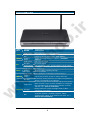
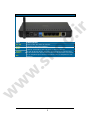
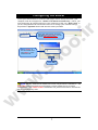
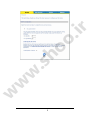
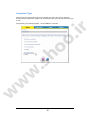
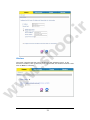
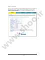
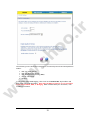
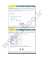
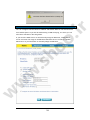
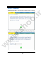
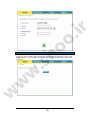
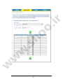
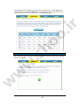
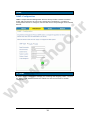
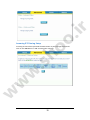
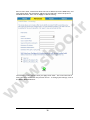
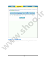
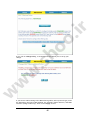
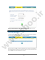
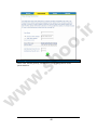
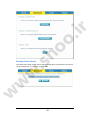
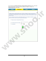
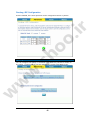
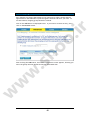
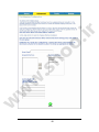
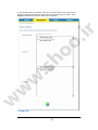
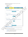
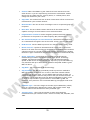
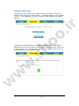
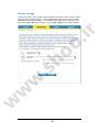
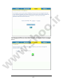
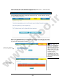
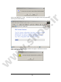
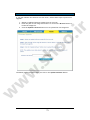
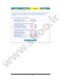
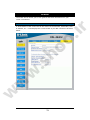
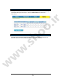
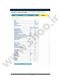
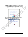
DSL-2640U
o.
ir
D-Link
Wireless ADSL2/2+ 4-port Ethernet Router
w
w
w
.s
ho
User Manual
Building Networks for People
RECYCLABLE
2006/11/08
Ver. 1.00
Table of Contents
w
w
w
.s
ho
o.
ir
.
GENERAL INFORMATION ......................................................................... 3
Package Contents ....................................................................... 3
Important Safety Instructions ......................................................... 3
Front Panel View ........................................................................ 4
Back Panel View ......................................................................... 5
CONNECTING THE ROUTER TO YOUR COMPUTER ................................................. 6
Connect the Telephone Cable ..................................................... 6
Connect the Ethernet Cable ....................................................... 6
Connect the Power Adapter........................................................ 6
CONFIGURING THE ROUTER ..................................................................... 7
HOME .......................................................................................... 8
Wizard .................................................................................... 8
ATM PVC Configuration .......................................................... 8
Connection Type ................................................................10
PPP Username and Password ..................................................11
Network Address Translation Settings........................................11
Device Setup .....................................................................12
Wireless ..........................................................................13
Setup - Summary ................................................................14
Wireless .................................................................................15
Wireless -- Basic.................................................................15
Wireless – Security ..............................................................16
WAN ......................................................................................17
LAN .......................................................................................24
DNS .......................................................................................26
DNS Server Configuration ......................................................26
Dynamic DNS ............................................................................27
Logout ...................................................................................28
ADVANCED SETUP .............................................................................29
ADSL......................................................................................29
ADSL Settings ....................................................................29
ADSL Tone Settings .............................................................30
Virtual Server ...........................................................................31
NAT—Virtual Servers Setup ....................................................31
DMZ ......................................................................................33
SNMP .....................................................................................34
SNMP—Configuration ............................................................34
IP Filter ..................................................................................34
Incoming IP Filtering Setup ....................................................35
Outgoing IP Filtering Setup ....................................................37
Bridge Filters ...........................................................................39
MAC Filtering Setup .............................................................39
Parental Control........................................................................41
Time of Day Restrictions .......................................................41
Routing ..................................................................................42
Routing--Static Route...........................................................43
Routing—Default Gateway .....................................................44
Routing—RIP Configuration ....................................................46
Quality of Service ......................................................................46
Port Mapping............................................................................48
Certificate...............................................................................50
Local ..............................................................................50
Trusted CA .......................................................................52
Wireless .................................................................................53
Wireless—Advance Setting .....................................................54
1
w
w
w
.s
ho
o.
ir
Wireless—MAC Filter ............................................................57
Wireless—Bridge .................................................................58
Wireless—QoS ....................................................................59
TOOLS ........................................................................................60
Access Control ..........................................................................60
Access Control—Admin .........................................................61
Access Control—Services .......................................................62
Access Control—IP Address.....................................................62
Time .....................................................................................64
Remote Log .............................................................................65
TR-069 Client ...........................................................................66
System ...................................................................................68
Save and Reboot.................................................................68
Backup Settings..................................................................68
Update Settings .................................................................69
Restore Default Settings .......................................................69
Firmware ................................................................................71
Test ......................................................................................72
STATUS .......................................................................................74
Device Info ..............................................................................74
DHCP Clients ............................................................................75
WAN Info ................................................................................76
Route Info ...............................................................................76
Log .......................................................................................77
LAN .......................................................................................78
WAN ......................................................................................79
ATM ......................................................................................79
ADSL......................................................................................81
ADSL BER Test ...................................................................82
Wireless Station Info...................................................................83
2
General Information
The D-Link DSL-2640U is an ADSL2+ router that provides a convenient wireless
routing function. This user manual offers you with a simple and easy-to-understand
format to install and configure your router.
o.
ir
Package Contents
Included in the package is one of each of the following—
•
•
•
•
•
•
DSL-2640U Wireless ADSL2/2+ 4-port Ethernet Router
Power adapter
RJ-11 telephone cable
RJ-45 Ethernet cable
CD-ROM (containing User Manual & Quick Guide)
Quick Guide (booklet)
.s
ho
Important Safety Instructions
Place your router on a flat surface close to the cables in a location with
sufficient ventilation. Do not mount this device on a wall.
•
To prevent overheating, do not obstruct the ventilation openings of this
equipment.
•
Plug this equipment into a surge protector to reduce the risk of damage
from power surges and lightning strikes.
•
Operate this equipment only from an electrical outlet with the correct
power source as indicated on the adapter.
•
Do not open the cover of this equipment. Opening the cover will void any
warranties on the equipment.
w
•
Unplug equipment first before cleaning. A damp cloth can be used to clean
the equipment. Do not use liquid / aerosol cleaners or magnetic / static
cleaning devices.
w
w
•
3
LED
Power
Status
DSL
Mode
Indication
Solid Green
No light
Red
Flashing
Green
Solid Green
No Light
Slow Flashing
Fast Flashing
Solid Green
Flashing
No Light
Solid Green
Flashing
Green
The router is powered on. (READY)
The power is off.
Failure or device malfunction. (NOT READY)
Traffic is passing through the device. (INTERNET
TRAFFIC)
DSL is synchronized.
No carrier signal.
DSL attempting synch. Trying to detect carrier signal.
Carrier has been detected and router is trying to train.
Wireless is up.
Wireless traffic is passing through.
Wireless is down.
Powered device connected to associated port
w
WLAN
.s
ho
o.
ir
Front Panel View
LAN 1-4
w
w
No Light
Solid Green
Internet
No Light
Red
LAN activity present (traffic in either direction).
No activity, router power off, no cable or no powered
device is connected to the LAN port.
IP connected (device has a WAN IP address from IPCP or
DHCP and DSL is up or a static IP address is configured,
PPP negotiation has completed successfully (if used),
and DSL is up. (WAN IP AVAILABLE)
Router power off, router in bridge mode or ADSL
connection not present.
Device attempted to become IP connected and failed
(no DHCP response, no PPPoE response, PPPoE
authentication failed, no IP address from IPCP, etc.).
(WAN IP NOT AVAILABLE)
4
o.
ir
Back Panel View
Description
On/ Off
Power
Press to turn the router on and off.
Connects to the power adapter.
Press for less than 3 seconds to reset the router.
Press for 3 seconds or more to revert to factory settings.
For use by D-Link service personnel for maintenance purposes only.
RJ-45 connects the unit to Ethernet devices such as a PC or a switch.
RJ-11 telephone port connects telephone cable to telephone or fax
machine.
Reset
Console
LAN 4-1
w
w
w
DSL
.s
ho
Port
5
Connecting the Router to Your Computer
Reset
Button
LAN
1-4
Console *
DSL
Port
o.
ir
Power
Input
.s
ho
On / Off
Button
* Console—for use by D-Link repair service personnel only.
Connect the Telephone Cable
•
Connect one end of the telephone cable to the DSL port on the router and
the other end of the cable into the wall socket.
w
Connect the Ethernet Cable
Connect one end of the Ethernet cable to one of the 4 LAN ports on the
back of the router and attach the other end to an Ethernet Adapter or
available Ethernet port on your computer. Or, you can attach it to a switch /
hub first and connect your computer to the switch / hub.
w
w
•
Connect the Power Adapter
•
Complete the process by connecting the power adapter to the Power input
on the back of the router and then plug the other end of power adapter into a
wall outlet or power strip. Then turn on the router and boot up your PC and
any LAN devices, such as hubs or switches, and any computers connected to
them.
6
Configuring the Router
o.
ir
To use your web browser to access the web pages used to set up the router, your
computer must be configured to “Obtain an IP address automatically”, that is, you
must change the IP network settings of your computer so that it is a DHCP client. If
you are using Windows XP and do not know how to change your network settings,
skip ahead to Appendix A and read the instructions provided.
Open your web browser and enter
the URL http://192.168.1.1 in the
address bar and press Enter.
.s
ho
Enter “admin” in
the User Name field
and “admin” in the
Password field.
w
Click OK
w
w
NOTE: Actually, there are two default user name and password combinations. The
user / user name and password combination provides limited access to certain
configurations. The admin / admin combination can perform all functions. Passwords
can be changed at any time.
7
Home
The home section provides configurations for general use, including a Quick Setup
Wizard with steps to quickly set up your router for Internet connection. Also
included in this section are LAN / WAN setup and DNS configuration. The below
sections explains the setup for each.
o.
ir
Wizard
This section will explain how to quickly configure the router if your only intention is
to access the Internet.
ATM PVC Configuration
To enable the auto-connect process, click on the box labeled DSL Auto-connect, a
process that will automatically detect the first usable PVC and automatically detect
PPPoE and PPPoA. To continue, click on the Next button.
w
w
w
.s
ho
Skip ahead to page 11 if you select DSL Auto-connect.
If you uncheck the DSL Auto-connect box, the resulting screen is seen below. Enter
the VPI / VCI as indicated by your ISP. Also shown will be the Quality of Service.
8
9
.s
ho
w
w
w
o.
ir
Connection Type
Following is the Connection Type screen where you select the type of network
protocol and encapsulation mode over the ATM PVC that your ISP has instructed you
to use.
w
w
w
.s
ho
o.
ir
The following is a PPPoA example. Click on Next to continue.
10
PPP Username and Password
w
w
.s
ho
o.
ir
Now, enter the PPP username and password as given by your ISP. Then decide if
you will be using any features such as Dial on demand, PPP IP extension, Keep Alive
and then click on Next.
Network Address Translation Settings
w
The next step is to configure the Network Address Translation (NAT) settings. For
the example, NAT will be enabled. The remaining fields are left as default and
then click on Next to continue.
11
o.
ir
.s
ho
Device Setup
w
w
w
You can configure the DSL Router IP address and Subnet Mask for the LAN interface
to correspond to your LAN’s IP Subnet. If you want the DHCP server to
automatically assign IP addresses, then enable the DHCP server and enter the range
of IP addresses that the DHCP server can assign to your computers. Disable the
DHCP server if you would like to manually assign IP addresses. Click on Next to
continue.
12
o.
ir
.s
ho
Wireless
w
w
w
The router’s wireless function can be enabled on the following screen. If the
function is enabled, then continue by entering the SSID, the wireless network name.
Click on Next to continue.
13
Setup - Summary
w
w
w
.s
ho
o.
ir
After all of the configurations are done, the WAN Setup Summary screen displays all
WAN settings that you have made. Check that the settings are correct before
clicking on the Save / Reboot button. Clicking on Save / Reboot will save your
settings and restart your router.
14
Wireless
Wireless -- Basic
w
w
w
.s
ho
o.
ir
The below Wireless – Basic screen lets you enable or disable wireless. The default
setting for wireless is enabled. You can also hide the access point so others cannot
see your ID on the network. Click on Apply to save your configurations before
clicking on Security to continue to the Security configurations.
15
Wireless – Security
The next screen is the Wireless – Security screen which allows you to select the
network authentication method and to enable or disable WEP encryption. Note
that depending on the network authentication that is selected, the screen will
change accordingly so additional fields can be configured for the specific
authentication method.
o.
ir
Network authentication methods include the following—
Open—anyone can access the network. The default is a disabled WEP
encryption setting.
•
Shared—WEP encryption is enabled and encryption key strength of 64-bit or
128-bit needs to be selected. Click on Set Encryption Keys to manually set
the network encryption keys. Up to 4 different keys can be set and you can
come back to select which one to use at anytime.
•
802.1X—requires mutual authentication between a client station and the
router by including a RADIUS-based authentication server. Information
about the RADIUS server such as its IP address, port and key must be
entered. WEP encryption is also enabled and the encryption strength must
also be selected.
•
WPA—(Wi-Fi Protected Access)— usually used for the larger Enterprise
environment, it uses a RADIUS server and TKIP (Temporal Key Integrity
Protocol) encryption (instead of WEP encryption which is disabled). TKIP
uses128-bit dynamic session keys (per user, per session, and per packet
keys).
•
WPA-PSK (Wi-Fi Protected Access – Pre-Shared Key)—WPA for home and
SOHO environments also using the same strong TKIP encryption, per-packet
key construction, and key management that WPA provides in the enterprise
environment. The main difference is that the password is entered manually.
A group re-key interval time is also required.
•
WPA2 (Wi-Fi Protected Access 2)—second generation of WPA which uses
AES (Advanced Encryption Standard) instead of TKIP as its encryption
method. Network re-auth interval is the time in which another key needs
to be dynamically issued.
•
WPA2-PSK (Wi-Fi Protected Access 2 – Pre-Shared Key)—suitable for home
and SOHO environments, it also uses AES encryption and requires you to
enter a password and an re-key interval time.
w
w
w
.s
ho
•
•
Mixed WPA2 / WPA—during transitional times for upgrades in the
enterprise environment, this mixed authentication method allows
“upgraded” and users not yet “upgraded” to access the network via the
router. RADIUS server information must be entered for WPA and a as well
as a group re-key interval time. Both TKIP and AES are used.
•
Mixed WPA2 / WPA-PSK—useful during transitional times for upgrades in
the home or SOHO environment, a pre-shared key must be entered along
with the group re-key interval time. Both TKIP and AES are also used.
16
o.
ir
.s
ho
WAN
w
w
w
Configure the WAN settings as provided by your ISP.
Click on the Add button if you want to add a new connection for the WAN interface
and to proceed to the ATM PVC Configuration screen as seen below. The ATM PVC
Configuration screen allows you to configure an ATM PVC identifier (VPI and VCI)
and select a service category.
17
Find out the following values from your ISP before you change them.
UBR Without PCR (Unspecified Bit Rate without Peak Cell Rate)—
UBR service is suitable for applications that can tolerate variable
delays and some cell losses. Applications suitable for UBR service
include text/data/image transfer, messaging, distribution, and
retrieval and also for remote terminal applications such as
telecommuting.
o
UBR With PCR (Unspecified Bit Rate with Peak Cell Rate)--
o
CBR (Constant Bit Rate)—used by applications that require a fixed
data rate that is continuously available during the connection time.
It is commonly used for uncompressed audio and video information
such as videoconferencing, interactive audio (telephony), audio /
video distribution (e.g. television, distance learning, and pay-perview), and audio / video retrieval (e.g. video-on-demand and audio
library).
o.
ir
o
o
Non Realtime VBR (Non-Real-time Variable Bit Rate)—can be used
for data transfers that have critical response-time requirements
such as airline reservations, banking transactions, and process
monitoring.
o
Realtime VBR (Real-time Variable Bit Rate)—used by time-sensitive
applications such as real-time video. Rt-VBR service allows the
network more flexibility than CBR.
Quality of Service: Can be enabled only for UBR without PCR, UBR with
PCR, and Non Realtime VPR.
w
w
w
•
VPI: Virtual Path Identifier. The valid range is 0 to 255.
VCI: Virtual Channel Identifier. The valid range is 32 to 65535.
Service Category: Five classes of traffic are listed—
.s
ho
•
•
•
18
o.
ir
.s
ho
w
The following screen shows the below types of network protocols and encapsulation
modes—
PPP over ATM (PPPoA)
PPP over Ethernet (PPPoE)
MAC Encapsulation Routing (MER)
IP over ATM (IpoA)
Bridging
w
•
•
•
•
•
w
If you will be using VLAN tagging, then click on the Enable 802.1q checkbox and
then enter the VLAN ID number. Note that the 802.1q function is only available
if you select PPPoE, MER, or Bridging. When finished with your selections, click
on Next to continue.
19
o.
ir
.s
ho
The following screen allows you to enter PPP username and password as well as
make any selections regarding your connection.
•
w
•
Dial on demand: Allows you to manually connect to the Internet so you are
not permanently connected. Idle timeout timer is included.
PPP IP extension: Used by some ISP’s. Check with your ISP to see if it is
required.
Keep alive: Keeps you connected to your ISP even when no activity is
present for a certain period of time.
Use static IP address: Select if you want to use a non-DHCP issued IP
address to connect to the Internet. If selected, you will be asked to enter
the static IP address.
•
w
w
•
20
o.
ir
.s
ho
w
When finished, click on Next to proceed to the NAT Settings screen.
•
w
w
•
Enable NAT: Select enable if you wish to share one WAN IP address for
multiple computers on your LAN.
Enable Firewall: Select if you wish to enable the router’s firewall for
security.
Enable IGMP Multicast: Select enable if you wish to be able to provide
multicasts, mostly used in video streaming.
Enable WAN Service: Select if you wish to use WAN service and then set
the service name.
•
•
21
o.
ir
.s
ho
w
w
w
Click Next when finished with your configurations and the below screen will follow
displaying the WAN settings that you made. When satisfied with the settings click
on the Apply button.
22
.s
ho
o.
ir
After you apply the configurations, it will return to the WAN Setup screen showing
the new configurations. Select the Finish button to save the changes and reboot
the router.
w
w
w
Below is the DSL Router Reboot screen that will appear during the rebooting
process.
When completed, the below pop-up window will appear confirmation that the
modem has been rebooted.
23
o.
ir
LAN
You can configure the DSL Router IP address and Subnet Mask for the LAN interface.
An available option if you will be multicasting is IGMP snooping, for which you can
also select standard or blocking mode.
w
w
w
.s
ho
If you want the DHCP server to automatically assign IP addresses, enable DHCP
server and enter the range of IP addresses that DHCP server can assign. Disable
DHCP server if you would like to manually assign IP addresses.
24
w
w
w
.s
ho
o.
ir
The Save button only saves the LAN configuration data, but does not apply the
configurations. Select the Save/Reboot button to save the LAN configuration data
and reboot the router and apply the new configurations.
25
DNS
DNS Server Configuration
.s
ho
o.
ir
Use the DNS Server screen to request automatic assignment of a DNS or to specify a
primary and secondary DNS.
w
w
w
If you uncheck the Enable Automatic Assigned DNS checkbox, two additional fields—
primary and secondary DNS server—will appear. Enter the information and click on
Apply to save the configuration.
26
Dynamic DNS
Dynamic DNS is a service for allowing an Internet domain name to be assigned to a
varying IP address. This makes it possible for other sites on the Internet to establish
connections to you without needing to track the IP address themselves. Click on
Add to set up a dynamic DNS configuration.
.s
ho
o.
ir
Note that the Add and Remove buttons will only show up if you have established a
WAN connection(s) (not including bridge connection).
w
w
w
This screen allows you to add a dynamic DNS address from DynDNS.org or TZO.
First select the D-DNS provider—DynDNS.org or TZO—from which you have obtained
a dynamic DNS address. Enter the hostname and the interface that you are using.
Also enter the username and password assigned by the DNS service. Click on Apply
to save these configurations.
27
o.
ir
.s
ho
Logout
w
w
w
To log out of the router’s user interface at any time during the setup, click on the
Logout button. A confirmation screen will appear confirming that you really want
to log out.
28
Advanced Setup
This section of the setup is an advanced version of the quick setup. If you want to
make specific configurations to your router such as creating a virtual server, DMZ,
RIP, Quality of Service (QoS), etc., consider going through this advanced setup for a
more comprehensive configuration.
o.
ir
ADSL
w
w
w
.s
ho
The ADSL settings page contains a modulation and capability section to be specified
by your ISP. Consult your ISP to select the correct settings for each. Then click on
Apply if you are finished or click on Advanced Settings if you want to configure
more advanced settings.
ADSL Settings
29
.s
ho
o.
ir
The test mode can be selected from the DSL Advanced Settings page. Test modes
include—normal, reverb, medley, no retrain, and L3. After you make your
selections of the test mode, click on Apply to save these settings first before you
go to Tone Selection.
ADSL Tone Settings
w
w
w
The frequency band of ADSL is split up into 256 separate tones, each spaced 4.3125
kHz apart. With each tone carrying separate data, the technique operates as if 256
separate routers were running in parallel. The tone range is from 0 to 31 for
upstream and from 32 to 255 for downstream. Do not change these settings unless
directed by your ISP.
30
o.
ir
.s
ho
Virtual Server
If you enable NAT (Network Address Translation), you can configure the Virtual
Server, Port Triggering, and DMZ Host.
NAT—Virtual Servers Setup
w
w
w
A virtual server allows you to direct incoming traffic from the WAN side to a
specific IP address on the LAN side.The following figure shows the screen that
allows you to configure your virtual server(s). Click on the Add button to configure
a virtual server.
Select the virtual server from the drop-down list and complete the server IP address,
then click on Apply once.
31
32
.s
ho
w
w
w
o.
ir
DMZ
.s
ho
o.
ir
The following screen appears after you save your selection. To add additional
virtual servers, click on the Add button. If you need to remove any of the server
names, select the check box and click on the Remove button.
w
w
w
You can define the IP address of the DMZ Host on this screen. Enter the IP address
and click on Apply.
33
SNMP
SNMP—Configuration
w
.s
ho
o.
ir
SNMP is Simple Network Management Protocol that provides a means to monitor
status and performance as well as set configuration parameters. It enables a
management station to configure, monitor and receive trap messages from network
devices.
IP Filter
w
w
IP filters can be configured to manage your incoming and outgoing traffic. Click on
the Inbound and Outbound buttons to advance to the next section for further
configuration.
34
o.
ir
Incoming IP Filtering Setup
w
w
w
.s
ho
Incoming IP filter allows specified the WAN traffic to pass through the firewall.
Click on the Add button to add incoming filter settings.
35
w
.s
ho
o.
ir
Enter a filter name, information about the source address (from the WAN side), and
information about the destination address (to the LAN side). Select the protocol
and WAN interface, then click on Apply to add the setting.
w
w
The following screen appears when you apply the IP filter. The screen lists the IP
filters that were added from the previous screen. To change your settings, click on
the Add or Remove buttons.
36
o.
ir
.s
ho
w
Outgoing IP Filtering Setup
w
w
The outgoing filter will block the LAN traffic from entering the WAN side. Click on
the Add button to create filters.
37
o.
ir
.s
ho
w
w
w
The below screen will appear when you click on Add. Input the filter name, source
information (from the LAN side), and destination information (from the WAN side).
Then click on Apply to save.
The following screen appears when you apply the IP filter. The screen lists the IP
filters that were added from the previous screen. To change your settings, click on
the Add or Remove buttons.
38
o.
ir
.s
ho
w
Bridge Filters
MAC Filtering Setup
w
w
MAC filtering can forward or block traffic by MAC address. You can change the
policy or add settings to the MAC filtering table using the MAC Filtering Setup
screen.
39
o.
ir
.s
ho
w
w
w
If you click on Change Policy, a confirmation dialog allows you to verify your
change.
If you want to add a setting to the MAC filtering table, select protocol type, enter
the destination and source MAC address, the necessary frame direction, and WAN
interface (bridge mode only). Then click on Apply to save.
40
o.
ir
.s
ho
After you save the settings, a screen showing the settings will appear. On this
screen you will be able to view and delete MAC filtering rules.
Parental Control
Time of Day Restrictions
w
w
w
In a home setting, parents can also restrict the day of the week certain computers
can access the router. Click on Add to set up the restrictions.
After you click you on Add, you will see the below screen where you will be able to
enter the MAC address of the PC that you wish to place on a time of day restriction.
Click on Apply to save the settings and to continue.
41
o.
ir
.s
ho
Routing
w
w
w
Static route, default gateway, and RIP type routing configurations can be
performed here.
42
o.
ir
.s
ho
Routing--Static Route
w
w
w
The Static Route page can be used to add a routing table (a maximum of 32 entries
can be configured). To proceed, click on Add.
43
.s
ho
o.
ir
Enter the route information and then apply your configurations.
Routing—Default Gateway
w
w
w
The router has the ability to accept the first received default gateway assignment
from one of the PPPoA, PPPoE or MER/DHCP enabled PVC’s. This function is
enabled by default as seen below.
44
w
w
w
.s
ho
o.
ir
If you uncheck the Enable Automatic Assigned Default Gateway option, the below
screen will be shown. Enter the default gateway IP address or select the
established gateway to be used.
45
Routing—RIP Configuration
.s
ho
o.
ir
If RIP is enabled, the router operation can be configured as active or passive.
Quality of Service
w
w
w
You can configure the Quality of Service to apply different priorities to traffic on
the router. Click on Add to view the Add Network Traffic Class Rule screen.
46
w
w
w
.s
ho
o.
ir
This screen allows you to add a network traffic class rule.
47
Port Mapping
Port mapping is a feature that allows you to open ports to allow certain Internet
applications on the WAN side to pass through the firewall and enter your LAN. To
use this feature, mapping groups should be created.
.s
ho
o.
ir
Click on the Add button as displayed below. If you need to remove an entry, then
click on the Remove button.
w
w
w
After clicking the Add button, the below configuration screen appears, allowing you
enter the groups and the interfaces they are associated with.
48
49
.s
ho
w
w
w
o.
ir
Certificate
Local
.s
ho
o.
ir
There are two types of certificates—local & trusted CA.
w
w
w
A local certificate identifies your router over the network. To apply for a
certificate, click on Create Certificate Request and if you have an existing
certificate, click on Import Certificate to retrieve it.
50
If you need to create a certificate request, enter the following information—
Certificate name
Common name
Organization name
State/province name
Country/region name.
w
w
w
.s
ho
o.
ir
•
•
•
•
•
51
w
w
w
.s
ho
o.
ir
If you already have a certificate, then you can simply import the certificate by
pasting the certificate content and private key into the space provided. Click
Apply to submit the request to import the certificate.
Trusted CA
52
o.
ir
The trusted certificate authority (CA) allows you to verify the certificates of your
peers. Note that you can store up to 4 certificates. The below screen also allows
you to view the CA’s that you may have already added and can be removed. Click
on Import Certificate to continue to the next screen.
w
w
w
.s
ho
Paste the content of the certificate that you wish to add and click Apply.
Wireless
53
The Wireless section under Advanced contains three sections for further
configurations. Sections include—
Advanced Settings
MAC Filter
Bridge
QoS (Quality of Service)
w
w
w
.s
ho
o.
ir
•
•
•
•
Wireless—Advance Setting
Advanced features of the wireless LAN interface can be configured in this section.
Settings can be configured for the following—
•
AP Isolation—if you select enable, then each of your wireless clients will
not be able to communicate with each other.
•
Band—a default setting at 2.4GHz – 802.11g
54
Channel—802.11b and 802.11g use channels to limit interference from
other devices. If you are experiencing interference with another 2.4Ghz
device such as a baby monitor, security alarm, or cordless phone, then
change the channel on your router.
•
54gTM Rate—the wireless link rate at which information will be received and
transmitted on your wireless network.
•
Multicast Rate—the rate at which a message is sent to a specified group of
recipients.
•
Basic Rate—the set of data transfer rates that all the stations will be
capable of using to receive frames from a wireless medium.
•
Fragmentation Threshold—used to fragment packets which help improve
performance in the presence of radio frequency (RF) interference.
•
RTS Threshold (Request to Send Threshold)—determines the packet size
of a transmission through the use of the router to help control traffic flow.
•
DTIM Interval—sets the Wake-up interval for clients in power-saving mode.
•
Beacon Interval—a packet of information that is sent from a connected
device to all other devices where it announces its availability and readiness.
A beacon interval is a period of time (sent with the beacon) before sending
the beacon again. The beacon interval may be adjusted in milliseconds (ms).
•
Xpress Technology—a technology that utilizes standards based on
framebursting to achieve higher throughput. With Xpress Technology
enabled, aggregate throughput (the sum of the individual throughput
speeds of each client on the network) can improve by up to 25% in 802.11g
only networks and up to 75% in mixed networks comprised of 802.11g and
802.11b device.
•
54g Mode— 54g is a Broadcom Wi-Fi technology.
•
54g Protection—the 802.11g standards provide a protection method so
802.11g and 802.11b devices can co-exist in the same network without
“speaking” at the same time. Do not disable 54g Protection if there is a
possibility that a 802.11b device may need to use your wireless network. In
Auto Mode, the wireless device will use RTS/CTS (Request to Send / Clear
to Send) to improve 802.11g performance in mixed 802.11g/802.11b
networks. Turn protection off to maximize 802.11g throughput under most
conditions.
w
w
w
.s
ho
o.
ir
•
•
Preamble Type— this is the length of the CRC (Cyclic Redundancy Check)
block for communication between the router and wireless clients. High
network traffic areas should select Short preamble type.
•
Transmit Power— this is the percentage of power that should be
transmitted from your wireless router. Select from 20%, 40%, 60%, 80%, and
100%.
55
56
.s
ho
w
w
w
o.
ir
Wireless—MAC Filter
.s
ho
o.
ir
The MAC Filter feature allows you to disable, allow or deny users access to the
wireless router based on their MAC address. To add MAC addresses, click on Add to
continue. Click on Remove if you want to take out a MAC address from the MAC
filter list.
w
w
w
The MAC filter screen allows you to manage MAC address filters. Add the MAC
addresses that you want to manage and then select the mode that you want to use
to manage them. You can disable this feature or you can allow or deny access to
the MAC addresses that you add to the list.
57
Wireless—Bridge
w
w
w
.s
ho
o.
ir
In this next screen, you can select which mode you want the router to be in, either
access point or wireless bridge. If you enable bridge restrict, then enter the MAC
addresses of the remote bridges. If you disable the bridge restrict function, then
there are no MAC addresses to enter. Click on Save / Apply to save and continue.
58
Wireless—QoS
WMM (Wi-Fi Multimedia) technology is available on the wireless router, allowing you
to give multimedia applications a higher quality of service and priority in a wireless
network so applications such as videos will be of higher quality. Enabling WMM may
delay the network traffic of other lower assigned quality applications.
o.
ir
WMM No Acknowledgement can be enabled if you enable WMM which refers to the
acknowledgement policy used at the MAC level.
w
w
w
.s
ho
To create a QoS entry, click the Add QoS Entry button to proceed to add or remove
traffic class rules for your network. Click on Save/Apply WME Settings.
59
Tools
•
•
•
•
•
Admin: Allows you to change the password for the various user
names available
Time: Allows you to set the router’s time
Remote Log: Allows you to view logs of the router’s activities
System: Allows you to perform functions such as save / reboot,
backup, update settings, and restore default settings
Firmware: Allows you to upgrade your router with new available
firmware versions
Test: Allows you to view test information for your Internet
connection
.s
ho
•
o.
ir
The tools section contains various administrator functions to maintain your router.
Sections include the following—Admin, Time, Remote Log, System, Firmware, and
Test.
Access Control
w
w
w
You can enable or disable some services of your router by LAN or WAN. If no WAN
connection is defined, only the LAN side can be configured.
60
Access Control—Admin
w
w
w
.s
ho
o.
ir
Three user names and passwords—admin, support, and user—can be used to
control your router. The passwords for these user names can be changed on the
following screen. Enter the user name followed by the old password and the new
password that you wish to change to.
61
Access Control—Services
.s
ho
o.
ir
Services that can be enabled / disabled on the LAN / WAN are FTP, HTTP, ICMP,
SNMP, Telnet, and TFTP.
Access Control—IP Address
w
Web access to the router can be limited when Access Control Mode is enabled. The
IP addresses of allowed hosts can be added using Access Control→IP Address.
w
w
Add the IP address to the IP address list by clicking on the Add button, then select
“Enabled” to enable Access Control Mode.
62
o.
ir
.s
ho
w
w
w
To assign the IP address of the management station that is permitted to access the
local management services, enter the IP address in the box and click on the Apply
button.
63
Time
.s
ho
o.
ir
The Time Settings page allows you to automatically synchronize your time with a
time server on the Internet.
w
w
w
If you choose to set the router’s time, click on the “automatically synchronize with
Internet time servers” checkbox and the below fields appear.
64
Select from the list of NTP (Network Time Protocol) time servers. Then select the
time zone that you are in and click on Apply to save.
Remote Log
.s
ho
o.
ir
The Log dialog allows you to view and configure the log. To view the log, click on
the View System Log button.
Below is the System Log screen which shows the date/time of the log, the facility
that was logged, the severity level and the log message. Click on Refresh to view
any new information that is logged.
w
w
w
System Log when log
mode is DISABLED
System Log when log
mode is ENABLED
65
NOTE: When you
click on the View System
Log button, the System
Log screen that you access
will be located under the
Status section (see screen
on left). To return to the
previous screen to
configure system log,
remember to click on the
Tools tab (located on top
row) first and then click on
Remotelog.
.s
ho
o.
ir
To configure the system log settings, click on the Configure System Log button to
view the following screen.
If the log is enabled, the system will log selected events including Emergency, Alert,
Critical, Error, Warning, Notice, Informational, and Debugging. All events above or
equal to the selected log level will be logged and displayed.
w
If the selected mode is “Remote” or “Both”, events will be sent to the specified IP
address and UDP port of a remote system log server. If the selected mode is “Local”
or “Both”, events will be recorded in the local memory. Select the desired values
and click on Apply to configure the system log options.
TR-069 Client
w
w
The router includes a TR-069 client, a WAN management protocol. All the values
are already filled in. If you wish to enable this protocol, then select enable. You
must click on the Apply button for the setting to take place.
66
67
.s
ho
w
w
w
o.
ir
System
The system section includes several tools on one page, including save and reboot,
backup settings, update settings, and restore default settings.
Save and Reboot
w
.s
ho
o.
ir
To save all configurations made, click on the Save/Reboot button. This will save
all your settings and restart the router for the settings to take effect.
w
w
When completed, the below pop-up window will appear confirmation that the
router has been rebooted.
Backup Settings
To save your configurations in a file on your computer so that it may be accessed
again later if your current settings are changed, click on the Backup Settings
button. The below pop-up screen will appear with a prompt to open or save the
file to your computer.
68
o.
ir
Update Settings
w
w
w
.s
ho
To load a previously saved configuration file onto your router, click Browse and
select the file on your computer and then click on Update Settings.
The router will restore settings and reboot to activate the restored settings.
Restore Default Settings
Restore Default will delete all current settings and restore the router to factory
default settings. Click on the Restore Default Settings button to proceed. The
following confirmation dialog will appear confirming your decision to restore
default settings. Click on OK to continue.
69
w
.s
ho
o.
ir
Click on the OK button to start. The below screen will appear with the progress of
restoring the default settings.
w
w
When completed, the below pop-up window will appear confirmation that the
router has been rebooted.
70
Firmware
If your ISP releases new software for this router, follow these steps to perform an
upgrade.
w
.s
ho
o.
ir
1. Obtain an updated software image file from your ISP.
2. Enter the path to the image file location or click on the Browse button to
locate the image file.
3. Click the Update Software button once to upload the new image file.
w
w
The below page will appear when you click on the Update Software button.
71
o.
ir
.s
ho
w
When completed, the below pop-up window will appear confirmation that the
router has been rebooted.
Test
w
w
The diagnostics screen allows you to run diagnostic tests to check your DSL
connection. The results will show test results of three connections—
•
•
•
Connection to your local network
Connection to your DSL service provider
Connection to your Internet service provider
There are three buttons at the bottom of the page—Next Connection (appears only
if you have created more than one connection), Test and Test with OAM F4—which
will allow you to retest if necessary.
72
73
.s
ho
w
w
w
o.
ir
Status
The status section allows you to view general and status information for your
router’s connection.
Device Info
w
w
w
.s
ho
o.
ir
It shows details of the router such as the version of the software, bootloader, LAN
IP address, etc. It also displays the current status of your DSL connection as shown
below—
74
DHCP Clients
w
w
w
.s
ho
o.
ir
Access the DHCP Leases screen by clicking “DHCP” under “Statistics”. This shows
the computers, identified by the hostname and MAC address that have acquired IP
addresses by the DHCP server with the time that the lease for the IP address is up.
75
WAN Info
.s
ho
o.
ir
The WAN Info screen displays WAN connections previously set up in the Home
section. The information added in the status section is the extra column for
connection status information, displaying either ADSL Link Down or ADSL Link Up.
Route Info
w
w
w
The Route Info section displays route information showing the IP addresses of the
destination, gateway, and subnet mask as well as other route information.
76
Log
w
w
w
.s
ho
o.
ir
This is the same screen as seen in the Remotelog section under tools.
77
LAN
w
w
w
.s
ho
o.
ir
The LAN section shows received and transmitted packet information for the
Ethernet interfaces. Click on Reset Statistics to renew the information.
78
WAN
ATM
.s
ho
o.
ir
The WAN section shows received and transmitted packet information for the WAN
connections that you have set up. Click on Reset Statistics to renew the
information.
w
w
w
The ATM section displays statistical values for your ATM interface as well as for
AAL5 and AAL5 VCC. Click on Reset Statistics to renew the values.
79
80
.s
ho
w
w
w
o.
ir
ADSL
w
w
w
.s
ho
o.
ir
Information contained in the ADSL screen is useful for troubleshooting and
diagnostics of connection problems.
81
ADSL BER Test
A Bit Error Rate Test (BER Test) is a test that reflects the ratio of error bits to the
total number transmitted.
.s
ho
o.
ir
If you click on the ADSL BER Test button at the bottom of the ADSL Statistics page,
the following pop-up screen will appear allowing you to set the tested time and to
begin the test.
w
w
w
When you start the ADSL BER Test, the following progress window will display the
connection speed as well as the length of time that the test will run for. At any
time during the test, click on the Stop button to terminate the test.
82
o.
ir
When the test is complete, the following window will display the test results
showing the test time, total transferred bits, total error bits and error ratio.
.s
ho
Wireless Station Info
w
w
w
This page displays the stations (identified by their BSSID) that are associated with
your wireless router. Click on Refresh to renew the page for new wireless stations.
83


![USER Manual for WiFi edited5[1] - the Naples Free-Net](http://vs1.manualzilla.com/store/data/005874834_1-4f1e4f9158101a49e1c12c3e2f124ebe-150x150.png)